

Page 1
Quick Installation Guide
Wireless Controller
This document will guide you through the
basic installation process for your
new D-Link Wireless Controller.
DWC-2000
Quick Installation Guide
Installationsanleitung
Guide d’installation
Guía de instalación
Guida di Installazione
Fan
Documentation is also available on
CD and the D-Link website
Page 2
About This Guide
This guide gives step-by-step instructions for
setting up your D-Link DWC-2000 Wireless
ENGLISH
Controller. Please note that the model you
have purchased may appear slightly different
from those shown in the illustrations.
The DWC-2000 Wireless Controller is a fullfeatured wireless LAN controller designed for
medium to large network environments. The
controller has a range of network and access
point management functions, can control up to
64 access points by default, and up to 256 with
license pack upgrades.
The DWC-2000 can be upgraded with three
optional license packs:
• The DWC-2000-AP32/DWC-2000-AP32LIC License Packs allow management of
up to 32 additional access points.
• The DWC-2000-AP64/DWC-2000-AP64LIC License Packs allow management of
up to 64 additional access points.
Item Part Description
A Reset button
B Power LED
C Fan LED
D USB ports (1-2)
Hard disk drive module
E
Gigabit LAN SFP ports
F
Gigabit LAN RJ-45
G
H Console port
I Power switch Powers On/Off the device
J Power outlet
slot
(1-4)
ports (1-4)
System reset
Indicates if the wireless
controller is powered on
Indicates the fan status
on the wireless controller
These ports can support
various USB 1.1 or 2.0
devices
Slot for the hard disk drive
module
Connect to Ethernet
devices such as
computers, switches, and
hubs
Connect to Ethernet
devices such as
computers, switches, and
hubs
Used to access the
Command Line Interface
(CLI) via an RJ-45 to
DB-9 console cable
Connects to the power
cord
• The DWC-2000-AP128/DWC-2000-AP128LIC License Packs allow management of
up to 128 additional access points.
The DWC-2000 can be upgraded multiple times
with license packs, enabling support for up to a
maximum of 256 access points.
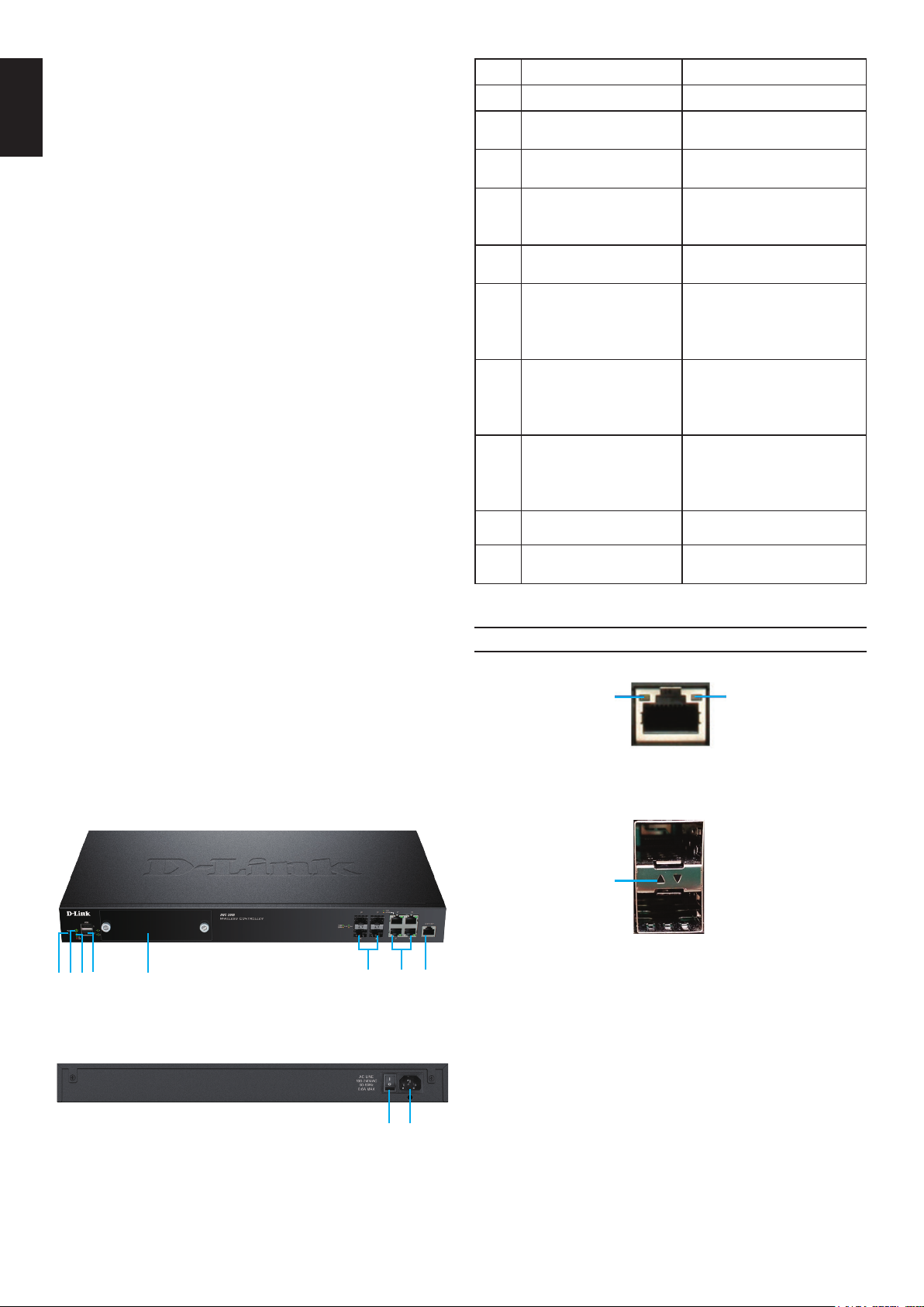
Product Overview
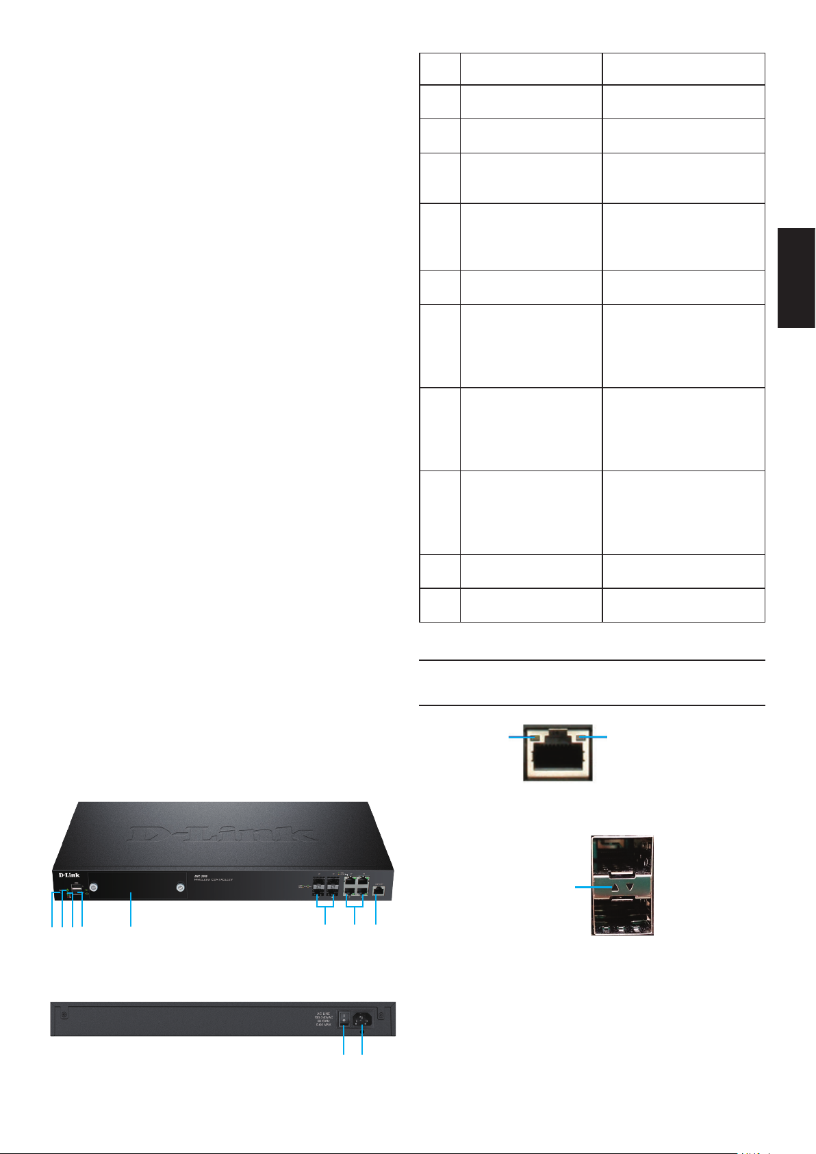
ABCD E
Figure 1. Front Panel
F G H
Status LEDs and Ethernet Port LEDs
Link
Speed
Figure 3. Ethernet RJ-45 Port LEDs
Link Speed &
TX/RX Status
Figure 4. Ethernet SFP Port LEDs
The following table lists the name, color, status,
and description of each device LED.
TX/RX
Status
2
Figure 2. Rear Panel
I
J
Page 3
LED
Indicator
Power/
Status
Fan Green/
USB Green Solid Green The link is good.
Tx/Rx
Status of
RJ-45 Port
Link Speed
of RJ-45
Port
Link and
TX/RX of
SFP Port
Color Status Description
Orange/
Green
Red
Green Solid Green Link is present.
Green/
Orange
Green/
Orange
Solid
Orange
Solid Green Power-on process
Blinking
Orange
Light Off The device is pow-
Solid Green The fan is operat-
Solid Red The fan has failed.
Blinking
Green
Light Off No link.
Blinking
Green
Link Off No link.
Solid Green Port is operating at
Solid
Orange
Light Off Port is operating at
Solid Green Port is operating at
Blinking
Green
Solid
Orange
Blinking
Orange
Power-on process
in progress.
complete.
Device has
crashed and is in
recovery mode.
ered off.
ing normally.
There is activity on
this port.
Port is sending or
receiving data.
100 Mbps.
Port is operating at
1000 Mbps.
10 Mbps.
100 Mbps.
Port is sending or
receiving data at
100 Mbps.
Port is operating at
1000 Mbps.
Port is sending or
receiving data at
1000 Mbps.
• Before installation, always check that the
power supply is disconnected.
• Ensure that the room in which you are
operating the device has adequate air
circulation and that the room temperature
does not exceed 40 °C (104 °F).
• Ensure there is at least one meter (three
feet) of clear space in front and back of the
device.
• Do not place the device in an equipment
rack frame that blocks the air vents on the
sides of the chassis. Ensure that enclosed
racks have fans and louvred sides.
• Ensure that none of these hazardous
conditions exist before installation: moist
or wet oors, leaks, ungrounded or frayed
power cables, or missing safety grounds.
Step 1 – Unpacking
Open the shipping carton and carefully unpack
its contents. Please consult the following
packing list to make sure that all items are
present and undamaged. If any item is missing
or damaged, please contact your local D-Link
reseller for a replacement.
Package Contents
DWC-2000 Wireless Controller 1
ENGLISH
Default Interface Settings
Ethernet
Interface
LAN (1-4) Static IP 192.168.10.1/24 Enabled
Interface
Type
IP Address Web-Based
Management
Installation and Connection
This section describes how to install a
DWC-2000 in a standard 19-inch equipment
rack and how to connect cables and power to
the device.
Before You Begin
Observe the following precautions to help
prevent shutdowns, equipment failures, and
injuries:
Power Cord 1
Console Cable
(RJ-45 to DB-9 Cable)
Ethernet Cable
(CAT5 UTP/Straight Through)
Reference CD 1
Rack Mounting Brackets 2
Screws Pack 1
QIG 1
1
1
3
Page 4
Step 2 – Installation
You can mount the DWC-2000 into a standard
19-inch equipment rack. To install the
ENGLISH
DWC-2000 into a rack:
1. Attach the mounting brackets to each side
of the chassis as shown in Figure 5 and
secure them with the screws provided.
Fan
Figure 5. Mounting Brackets
2. Use the screws provided with the equipment
rack to mount the device in the rack as
shown in Figure 6.
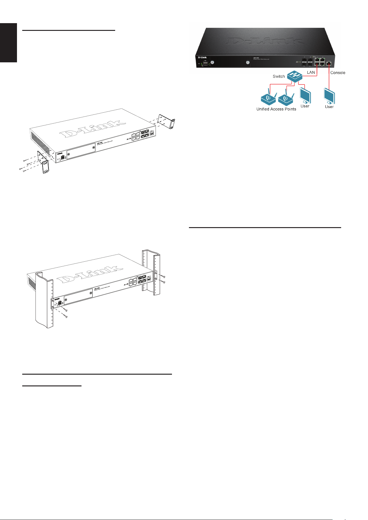
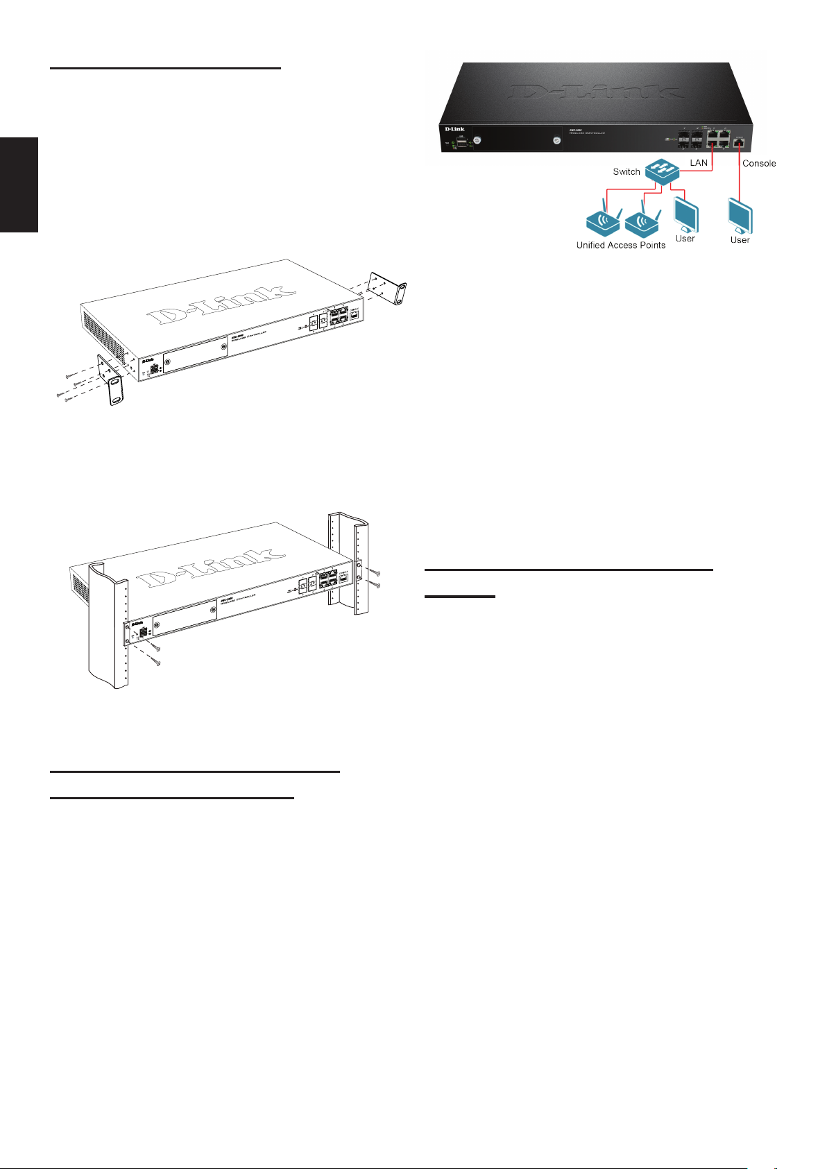
Figure 7. Connecting to Your Network
1. Connect an RJ-45 cable from one of the
ports labelled LAN (1-4) to a switch in the
LAN network segment.
2. Connect an RJ-45 to DB-9 cable from the
console port to a workstation to use the CLI
(Command Line Interface) for management.
Step 4 – Powering on the Device
Fan
Figure 6. Mount into the Rack
Step 3 – Connecting the Device
to a Network
This section provides basic information about
physically connecting the DWC-2000 to a
network.
The AC power cord shipped with the device
connects the device to earth ground when
plugged into a grounded AC power outlet.
The device must be grounded during normal
operation.
To connect the device to a power source, plug
one end of the AC power cord into the AC power
connector on the back panel of the device. Plug
the other end into an electrical outlet and switch
ON the power switch.
Note: We recommend using a surge protector
for the power connection.
Connect the necessary cables as shown in
Figure 7.
4
Page 5

Initial Conguration
The wireless controller software is preinstalled
on the DWC-2000. When the device is powered
on, it is ready to be congured. It comes with
a default factory conguration that allows
you to connect to it, but you should congure
the controller for your specic network
requirements.
Discovering the Wireless
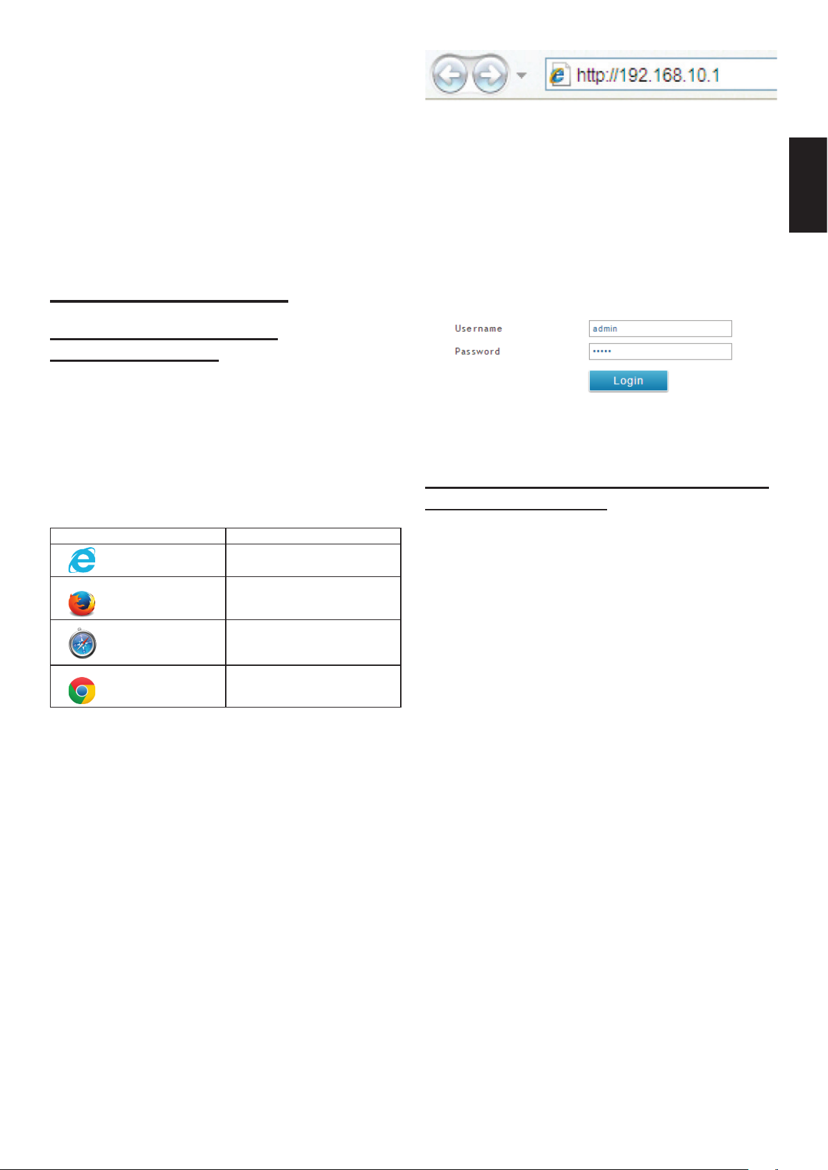
4. Log into the wireless controller Web
interface. The default login information is:
• Username: admin
• Password: admin
ENGLISH
Controller
Using the Web UI
To use the Web UI, the workstation from which
you are managing the device must initially be
on the same subnet as the device. You will also
need a compatible browser:
Browser Minimum Version
Microsoft
Internet Explorer
Mozilla Firefox 23
Apple Safari
Google Chrome 26
To access the device’s Web UI:
1. Connect your workstation to one of the ports
labelled LAN (1-4).
9, 10
iOS: 6.1.3
Windows: 5.1.7
Figure 9. Login Page
Connecting via Console (RJ-45 to DB-9
DCE)
The DWC-2000 Wireless Controller provides
a serial port that allows you to connect to
a computer or terminal for monitoring and
conguring the device. This port is an RJ-45
connector, and is implemented as a data
communication terminal equipment (DCE)
connection.
To use the console port connection, you
need the following equipment:
1. A terminal or a computer with both a serial
port and the ability to emulate a terminal.
2. The included RJ-45 to DB-9 cable.
3. If your laptop or PC does not have an
RS-232 connector, a converter (not
included) is required.
To establish a console connection:
2. Ensure your workstation is congured with
a static IP address in the 192.168.10.0/24
subnet.
Note: To avoid issues, disable any pop-up
blocking software or add the management
IP address http://192.168.10.1 to your
pop-up blocker’s allow list.
3. Launch your browser and enter the IP
address for the LAN interface (The default
IP address is http://192.168.10.1), then
press Enter.
Figure 8. Using the Browser
1. Plug the RJ-45 connector end of the
supplied RJ-45 to DB-9 cable directly into
the console port on the wireless controller.
2. Connect the other end of the cable to
a terminal or to the serial connector of
a computer running terminal emulation
software. Set the terminal emulation
software values as follows:
• Baud rate: 115200
• Data bits: 8
• Parity: None
• Stop bits: 1
• Flow control: None
5
Page 6
3. Connect the wireless controller following the
instructions in the “Powering on the Device”
section in this guide. The boot sequence will
be displayed on the terminal.
ENGLISH
4. Once the boot sequence is completed, the
command prompt will be displayed and the
device is ready to be congured.
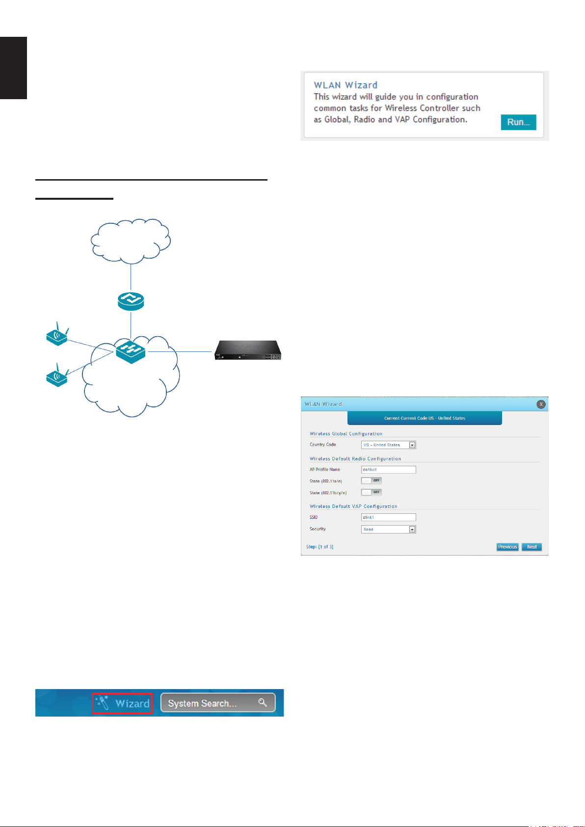
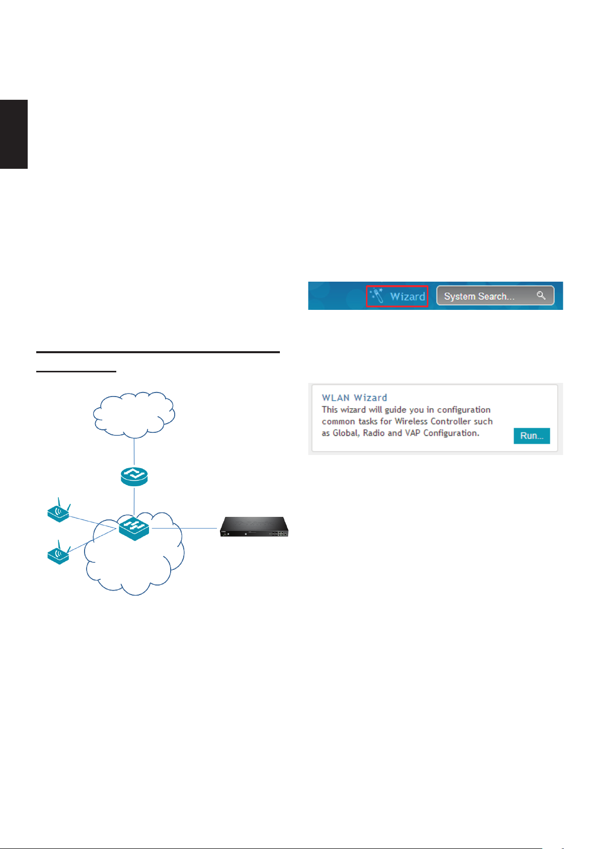
5. Click the “Run…” button to run the WLAN
Wizard.
Figure 12. Run WLAN Wizard
Discovering and Managing the
Unied AP
Internet
Router/
DHCP
Server
LAN
Switch
LAN
Unied
Access
Point
DWC-2000
1. Enter the following information to
complete the WLAN Setup Wizard:
• Wireless Global Conguration: Choose
the country code.
• Wireless Default Radio Conguration:
Create an AP Prole for the radio setting
of the wireless network. Set the radio
mode for each radio.
• Wireless Default VAP Conguration:
Enter the SSID network name, and then
select a security method. If you select
Static WEP or WPA Personal, enter a
secure passphrase for your WLAN.
Figure 10. Network Topology
To discover and manage the Unied AP:
1. Record the MAC address of each Unied
AP on the network.
2. Connect the Unied AP you want to congure
to the local area Ethernet network.
3. Log into the DWC-2000 and set the LAN IP
address to be in the subnet of the local area
Ethernet network.
4. Go through the Wizard to manage your
access points. Click “Wizard” at the top right
corner.
Figure 11. Wizard
Figure 13. WLAN Wizard
2. Below are two methods to add access
points in the managed AP list:
a. List of APs Awaiting to be Congured:
Select the access points which are
discovered automatically by the wireless
controller.
b. Valid Access Point Summary: Enter
access point MAC address manually.
List of APs Awaiting to be Congured: This
is a list of discovered access points. Switch
the Status of the access point you want to
manage to ON.
6
Page 7
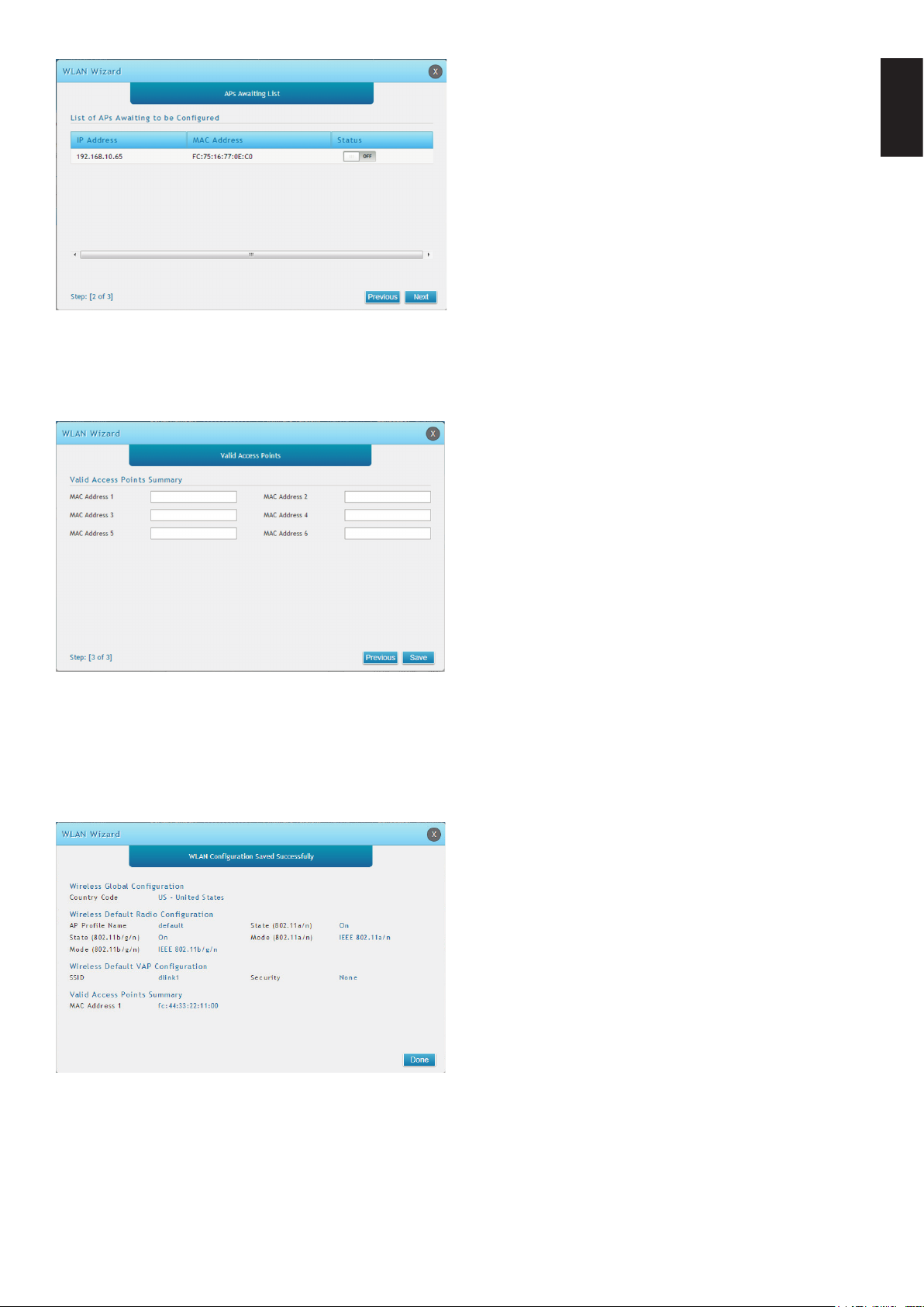
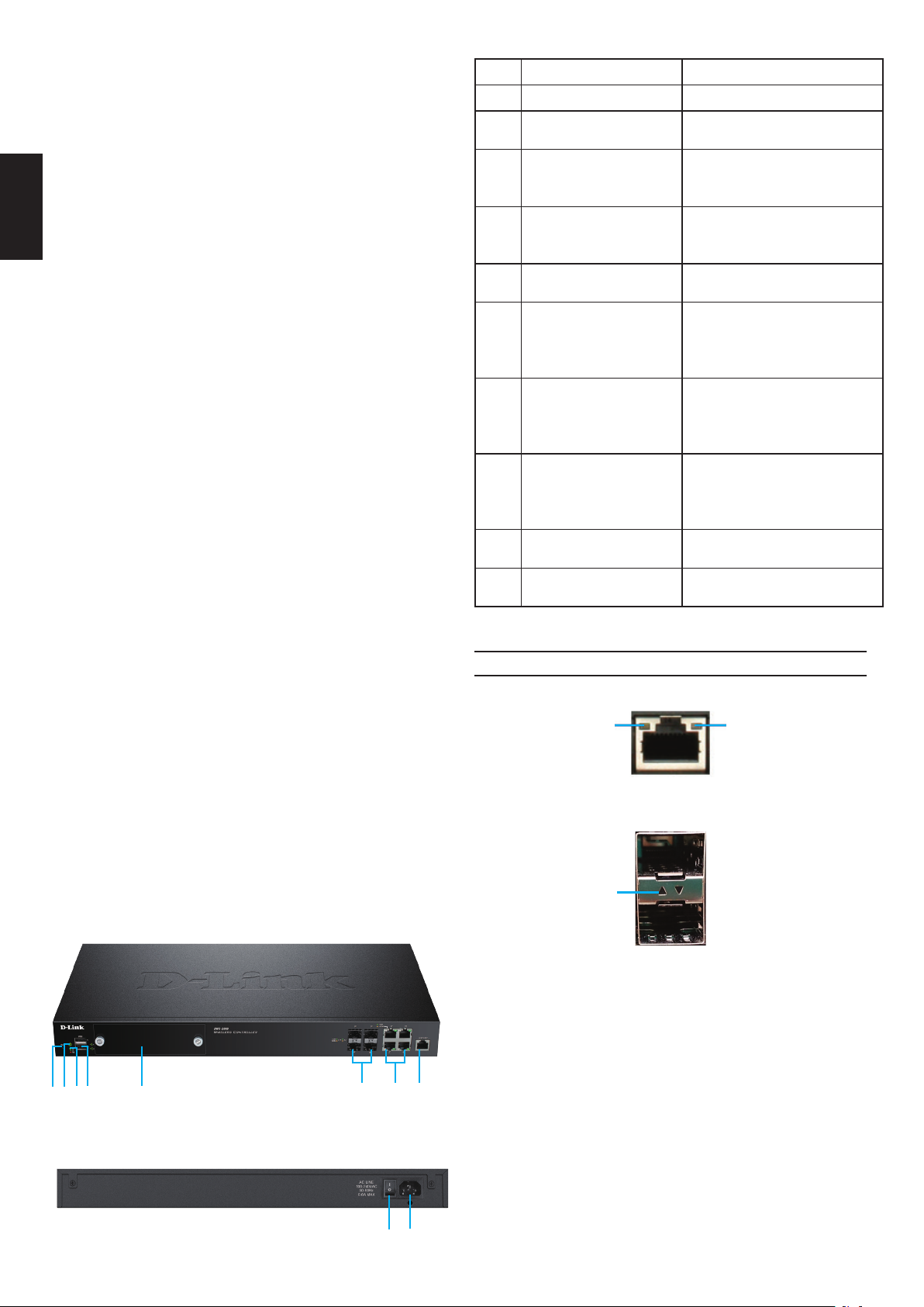
Figure 14. Congure AP
Valid Access Point Summary: Enter the
MAC address of the AP you want to manage.
Additional Information
ENGLISH
You can refer to the additional documentation
on the accompanying master CD or you
can visit http://support.dlink.com online
for more support on how to congure
your DWC-2000.
• D-Link Wireless Controller User Manual
This manual describes the general
operation and control of the wireless
controller rmware which drives and
controls the wireless controller hardware.
It includes examples of how to carry out
typical administrative tasks such as setting
up Rogue AP detection and how to use the
wireless controller in various scenarios.
• D-Link Wireless Controller CLI Reference
Guide
This document describes all available textbased commands that can be used on an
RJ-45 to DB-9 Console or SSH interface to
congure the wireless controller.
Figure 15. Enter MAC addresses
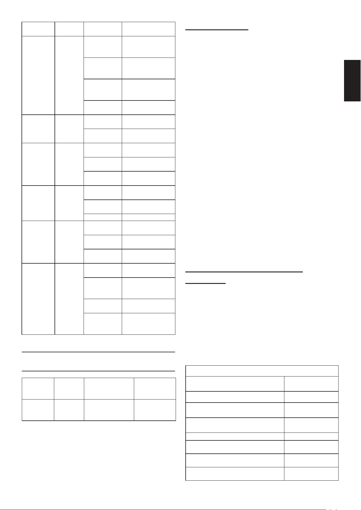
3. Save Settings and Connect - When the
WLAN Connection Setup Wizard has been
completed, click the Connect button to save
your settings and connect your APs.
Online Support
If there are any issues which are not in the user
manual, please visit http://support.dlink.com,
which will direct you to your appropriate local
D-Link support website.
Warranty Information
The D-Link Limited Lifetime Warranty
information is available at http://warranty.dlink.
com/
Figure 16. Summary
7
Page 8
Informationen zum Handbuch
Dieses Handbuch enthält ausführliche Anleitungen
zum Einrichten Ihres DWC-2000 Wireless
Controllers von D-Link. Beachten Sie, dass Ihr
Modell sich möglicherweise geringfügig von denen
der Abbildungen unterscheidet.
Bei dem DWC-2000 Wireless Controller handelt
es sich um einen für mittelgroße und große
DEUTSCH
Netwerkumgebungen entwickelten und mit
umfangreichen Funktionen ausgestatteten
WLAN Controller. Der Controller bietet eine
Reihe von Netzwerk- und Access PointManagementfunktionen und kann standardmäßig
bis zu 64 Access Points steuern und bis zu 256 mit
Lizenzpaket-Upgrades versorgen.
Für ein Upgrade des DWC-2000 stehen Ihnen
wahlweise die folgenden drei Lizenzpakete zur
Verfügung:
• Die Lizenzpakete DWC-2000-AP32/
DWC-2000-AP32-LIC ermöglichen das
Management bis zu 32 zusätzlicher Access
Points.
• Die Lizenzpakete DWC-2000-AP64/
DWC-2000-AP64-LIC ermöglichen das
Management bis zu 64 zusätzlicher Access
Points.
Ref. Element Beschreibung
A Rücksetztaste (Reset)
B LED-Betriebsanzeige
C Lüfter-LED
D USB-Ports (1-2)
E
G
H Konsolenport
Festplattenmodul-
Steckplatz
Gigabit LAN SFP Ports
F
Gigabit LAN RJ-45
I Ein-/Aus-Schalter
J Stromamschluss
(1-4)
Ports (1-4)
System zurücksetzen
Zeigt an, ob der Wireless
Controller eingeschaltet ist.
Zeigt den Status des
Wireless Controller-Lüfters
an
Diese Ports können
verschiedene USB 1.1 oder
2.0 Geräte unterstützen.
Ein Steckplatz für das
Festplattenlaufwerkmodul
Für den Anschluss von
Ethernet-Geräten wie
Computer, Switches und
Hubs
Für den Anschluss von
Ethernet-Geräten wie
Computer, Switches und
Hubs
Zum Zugriff auf die CLI
(Befehlszeilenschnittstelle)
über ein RJ-45-zu-DB-9
Konsolenkabel
Zum Ein-/Ausschalten des
Geräts
Zum Anschluss des
Netzkabels
• Die Lizenzpakete DWC-2000-AP128/
DWC-2000-AP128-LIC ermöglichen das
Management bis zu 128 zusätzlicher Access
Points.
Ein Upgrade des DWC-2000 kann mithilfe dieser
Lizenzpakete mehrere Male erfolgen und ermöglicht so eine Unterstützung von maximal 256
Access Points.
Produktübersicht
ABCD E
F G H
Status-LEDs und Ethernet-Port-LEDs
Link-
Geschwindigkeit
Abbildung 3. Ethernet RJ-45 Port LEDs
Link-Geschwindigkeit
& TX/RX-Status
Abbildung 4. Ethernet SFP Port LEDs
In der folgenden Tabelle sind Name, Farbe,
Status und Beschreibung für jede Geräte-LED
aufgeführt.
TX/RX-
Status
8
Abbildung 1. Vorderseite
Abbildung 2. Rückseite
I
J
Page 9
LED-An-
zeige
Betriebs-
anzeige/
Status
Lüfter Grün/Rot Durchgehend
USB Grün Durchgehend
Tx/Rx Sta-
tus des RJ-
45 Ports
Verbindungs-
geschw.
des RJ-45
Ports
Verb. u.
TX/RX des
SFP-Ports
Farbe Status Beschreibung
Orange-
farben/
Grün
Grün Durchgehend
Grün/
Orange-
farben
Grün/
Orange-
farben
Durchgehend
orangefarben
Durchgehend
grün
Blinkt
orangefarben
Leuchtet
nicht
grün
Durchgehend
rot
grün
Grün
blinkend
Leuchtet
nicht
grün
Grün
blinkend
Verb. aus Keine Verbindung.
Durchgehend
grün
Durchgehend
orangefarben
Leuchtet
nicht
Durchgehend
grün
Grün
blinkend
Durchgehend
orangefarben
Blinkt
orangefarben
Einschalt- und
Hochfahrvorgang
Einschalt- und
Hochfahrvorgang
abgeschlossen.
Gerät abgestürzt
und im Wiederher-
ausgeschaltet.
Der Lüfter arbeitet
ordnungsgemäß.
Gute Verbindung.
Dieser Port ist
Keine Verbindung.
Verbindung ist
Port sendet oder
empfängt Daten.
Port-Betrieb mit
Port-Betrieb mit
Port-Betrieb mit
Port-Betrieb mit
Port sendet oder
empfängt Daten
mit 100 Mbit/s.
Port-Betrieb mit
Port sendet oder
empfängt Daten
mit 1000 Mbit/s.
Standardeinstellungen für die
Schnittstellen
im Gange.
stellmodus.
Das Gerät ist
Der Lüfter ist
ausgefallen.
aktiv.
hergestellt.
100 Mbit/s.
1000 Mbit/s.
10 Mbit/s.
100 Mbit/s.
1000 Mbit/s.
Erste Schritte
Beachten Sie die folgenden Vorsichtsmaßnahmen,
um Fehler, Geräteausfälle und Verletzungen zu
vermeiden:
• Vor der Installation muss die Stromversorgung
getrennt werden.
• Das Gerät muss in einem Raum mit
ausreichender Belüftung betrieben werden.
Die Raumtemperatur darf 40 °C nicht
überschreiten.°
• Vor und hinter dem Gerät muss freier Platz
von mindestens 1 Meter sein.
• Achten Sie beim Installieren des Geräts
in einem Rackrahmen darauf, dass die
Lüftungsöffnungen an den Seiten des
Gehäuses nicht blockiert sind. Stellen Sie
sicher, dass geschlossene Racks über Lüfter
und seitliche Lüftungsschlitze verfügen.
• Beseitigen Sie vor der Installation die
folgenden Gefahrenquellen: feuchte oder
nasse Böden, Lecks, beschädigte oder
nicht geerdete Stromkabel und fehlende
Sicherheitserdungen.
Schritt 1: - Auspacken des
Produkts
Öffnen Sie den Versandkarton, entnehmen Sie
den Inhalt und packen Sie ihn vorsichtig aus.
Stellen Sie bitte sicher, dass alle auf der folgenden
Packliste aufgeführten Artikel auch tatsächlich
geliefert wurden und unbeschädigt sind. Sollte ein
Artikel fehlen oder beschädigt sein, wenden Sie
sich zum Zwecke einer Ersatzlieferung umgehend
an Ihren D-Link-Fachhändler.
Packungsinhalt
DEUTSCH
Ethernet-
Schnitt-
stelle
LAN (1-4) Statische
Schnitt-
stellentyp
IP-Adres-
se
IP-Adresse Webbasiertes
Management
192.168.10.1/24 Aktiviert
Installation und Verbindung
In diesem Abschnitt wird beschrieben, wie Sie ein
DWC-2000-Gerät in einem 19-Zoll-Standardrack
installieren und Kabel am Gerät anschließen.
DWC-2000 Wireless Controller 1
Netzkabel 1
Konsolenkabel (RJ-45-zu-DB-9-
Kabel)
Ethernet-Kabel (CAT5 UTP/Straight-
Through)
Reference CD 1
Rackmontagehalterungen 2
Schraubensätze 1
Installationsanleitung 1
1
1
9
Page 10
Schritt 2 – Installation
Der DWC-2000 kann in ein Geräterack mit
einer Standardgröße von 19 Zoll eingebaut
werden. So installieren Sie den DWC-2000 in
einem Rack:
1. Bringen Sie die Befestigungsklammern an
DEUTSCH
den beiden Seiten des Gehäuses an, wie in
Abbildung 5 gezeigt, und xieren Sie sie
mit den mitgelieferten Schrauben.
Fan
Abbildung 7. Anschluss an Ihr Netzwerk
1. Verbinden Sie einen der mit LAN
gekennzeichneten Ports (1-4) mithilfe eines
RJ-45-Kabels mit einem Switch im LANNetzwerksegment.
Abbildung 5. Rackbefestigungsklammern
2. Befestigen Sie das Gerät mithilfe der
mit dem Rack gelieferten Schrauben im
Geräterack (siehe Abbildung 6).
Fan
Abbildung 6. Montage im Rack
Schritt 3 - Anschließen des
Geräts an ein Netzwerk
In diesem Abschnitt wird der physische
Anschluss des DWC-2000 an ein Netzwerk
beschrieben.
Schließen Sie die erforderlichen Kabel an
(siehe Abbildung 7).
2. Verbinden Sie den Konsolenport mithilfe
eines RJ-45-zu-DB-9-Kabels mit einem
Arbeitsplatzrechner, um die Verwaltung
über die CLI (Command Line Interface/
Befehlszeilenschnittstelle) zu ermöglichen.
Schritt 4 – Einschalten des
Geräts
Das zusammen mit dem Gerät gelieferte
Netzkabel verbindet das Gerät mit Masse,
wenn es an eine Schuko-Netzsteckdose
angeschlossen wird. Das Gerät muss während
des normalen Betriebs geerdet sein.
Stecken Sie zur Stromversorgung des Geräts ein
Ende des Netzkabels in den Netzstromeingang
auf der Geräterückseite. Stecken Sie das
andere Kabelende in eine Steckdose und
schalten Sie die Stromzufuhr ein (bzw. stellen
Sie den Schalter auf ON (EIN)).
Hinweis: D-Link empehlt die Verwendung
eines Überspannungsschutzes für die
Stromverbindung.
10
Page 11
Erstkonguration
Die Wireless Controller-Software ist bereits
auf dem DWC-2000 vorinstalliert. Sobald das
Gerät eingeschaltet ist, kann es konguriert
werden. Obwohl das Gerät eine werkseitige
Standardkonguration aufweist, die es Ihnen
ermöglicht, eine Verbindung zu dem Gerät
herzustellen, sollten Sie den Controller
für Ihre speziellen Netzwerkerfordernisse
kongurieren.
Ihr Wireless Controller
Die webbasierte grasche
Benutzeroberäche
Damit Sie die webbasierte grasche
Benutzeroberäche (Web UI) verwenden
können, muss sich der Arbeitsplatzrechner,
mit dem das Gerät verwaltet wird, zunächst
im gleichen Subnetz wie das Gerät benden.
Sie benötigen außerdem einen kompatiblen
Browser:
Abbildung 8. Die Verwendung des Browsers
DEUTSCH
4. Melden Sie sich auf der webbasierten
Benutzeroberäche des Wireless Controller an.
Die standardmäßigen Anmeldeinformationen
sind:
• Username (Benutzername): admin
• Password (Kennwort): admin
Abbildung 9. Anmeldeseite
Verbindung über die Konsole (RJ-45-zuDB-9 DCE) herstellen
Browser Minimum Version
Microsoft
Internet Explorer
Mozilla Firefox 23
Apple Safari
Google Chrome 26
9, 10
iOS: 6.1.3
Windows: 5.1.7
Zugriff auf die Web-UI des Geräts:
1. Schließen Sie Ihren Arbeitsplatzrechner
an einen der Ports an, der mit LAN (1-4)
gekennzeichnet ist.
2. Stellen Sie sicher, dass der Arbeitsplatzrechner
mit einer statischen IP-Adresse im Subnetz
192.168.10.0/24 konguriert ist.
Hinweis: Um potentielle Problem zu vermeiden,
deaktivieren Sie die Popup-Blocker-Software
oder fügen Sie die Management-IP-Adresse
http://192.168.10.1 der Liste der zugelassenen
Adressen Ihrer Popup-Blocker-Software hinzu.
Ihr DWC-2000 Wireless Controller bietet einen
seriellen Port, über den Sie einen Computer oder
ein Terminal zur Überwachung und Konguration
des Geräts anschließen können. Dieser Port
verwendet einen RJ-45-Verbindungsstecker zur
Verbindung mit einem Datenkommunikationsgerät
(DCE, z. B. einem Modem).
Zur Verwendung der Konsolenport-Verbindung
benötigen Sie Folgendes:
1. Ein Terminal oder einen Computer
mit einem seriellen Port und TerminalEmulationsfähigkeiten.
2. Das im Lieferumfang enthaltene RJ-45-zu-DB9-Kabel.
3. Weist Ihr Laptop oder PC keine RS-232Anschlussbuchse auf, ist ein Konverter (nicht
im Lieferumfang enthalten) nötig.
So stellen Sie eine Konsolenverbindung her:
1. Stecken Sie den RJ-45-Verbindungsstecker
des mitgelieferten RJ45-zu-DB9-Kabels direkt
in den Konsolenport des Wireless Controllers.
3. Starten Sie Ihren Browser und geben Sie die
IP-Adresse für die LAN-Schnittstelle ein. (Die
vorgegebene Standard-IP-Adresse ist
http://192.168.10.1). Drücken Sie dann auf
die Eingabetaste.
2. Schließen Sie das andere Ende des Kabels an
ein Terminal oder an den seriellen Anschluss
eines Computers an, auf dem Terminal-
11
Page 12
Emulations-Software ausgeführt wird. Nehmen
Sie in der Terminal-Emulations-Software
folgende Einstellungen vor:
• Baud rate (Baudrate): 115200
• Data bits (Datenbits): 8
• Parity (Parität): None (Keine)
• Stop bits (Stoppbits): 1
DEUTSCH
• Flow Control (Datenusssteuerung): None
(Keine)
3. Schließen Sie den Wireless Controller an, indem
Sie den Anleitungen im Abschnitt "Einschalten
des Geräts" dieses Handbuchs folgen. Die
Startsequenz wird am Terminal angezeigt.
4. Nach Abschluss der Startsequenz wird
die Eingabeaufforderung der Befehlszeile
angezeigt. Das Gerät kann jetzt konguriert
werden.
So nutzen Sie die Verwaltungsfunktionen
des Unied AP:
1. Erfassen Sie die MAC-Adresse jedes Unied
AP im Netz.
2. Verbinden Sie den Unied AP, den Sie
kongurieren möchten, mit dem Ethernet-LAN.
3. Melden Sie sich auf dem DWC-2000 an und
kongurieren Sie die LAN IP-Adresse passend
zu dem IP-Subnetz in Ihrem Ethernet-LAN.
4. Folgen Sie den Anweisungen des Assistenten
zum Einsatz und zur Verwaltung Ihrer Access
Point. Klicken in der oberen rechten Ecke auf
“Wizard” (Assistent).
Abbildung 11. Der Assistent
Die Verwaltungsfunktionen des
Unied AP
Internet
Router/
DHCP-
Server
LAN
Switch
LAN
Unied
Access
Point
Abbildung 10. Netzwerktopologie
DWC-2000
5. Klicken Sie auf “Run…” (Ausführen), um den
WLAN-Assistenten auszuführen.
Abbildung 12. Den WLAN-Assistenten ausführen
1. Geben Sie die folgenden Informationen zur
Fertigstellung des WLAN Setup-Assistenten
ein:
• Wireless Global Conguration (Konguration
globaler drahtloser Verbindungen): Wählen
Sie den Ländercode.
• Wireless Default Radio Conguration
(Standardkonguration für die
Funkverbindung): Erstellen Sie ein AP-
Prol für die Funkeinstellung des drahtlosen
Netzwerks. Richten Sie den Funkmodus
jeder Funkfrequenz ein.
12
• Wireless Default VAP Conguration
(Standardkonguration der virtuellen
WLAN Basisstation): Geben Sie den
Netzwerknamen (SSID) ein und wählen
Sie eine Verschlüsselungsmethode. Geben
Sie ein sicheres Kennwort (Passphrase) für
Ihr WLAN ein, wenn Sie 'Static WEP' oder
'WPA Personal' wählen.
Page 13
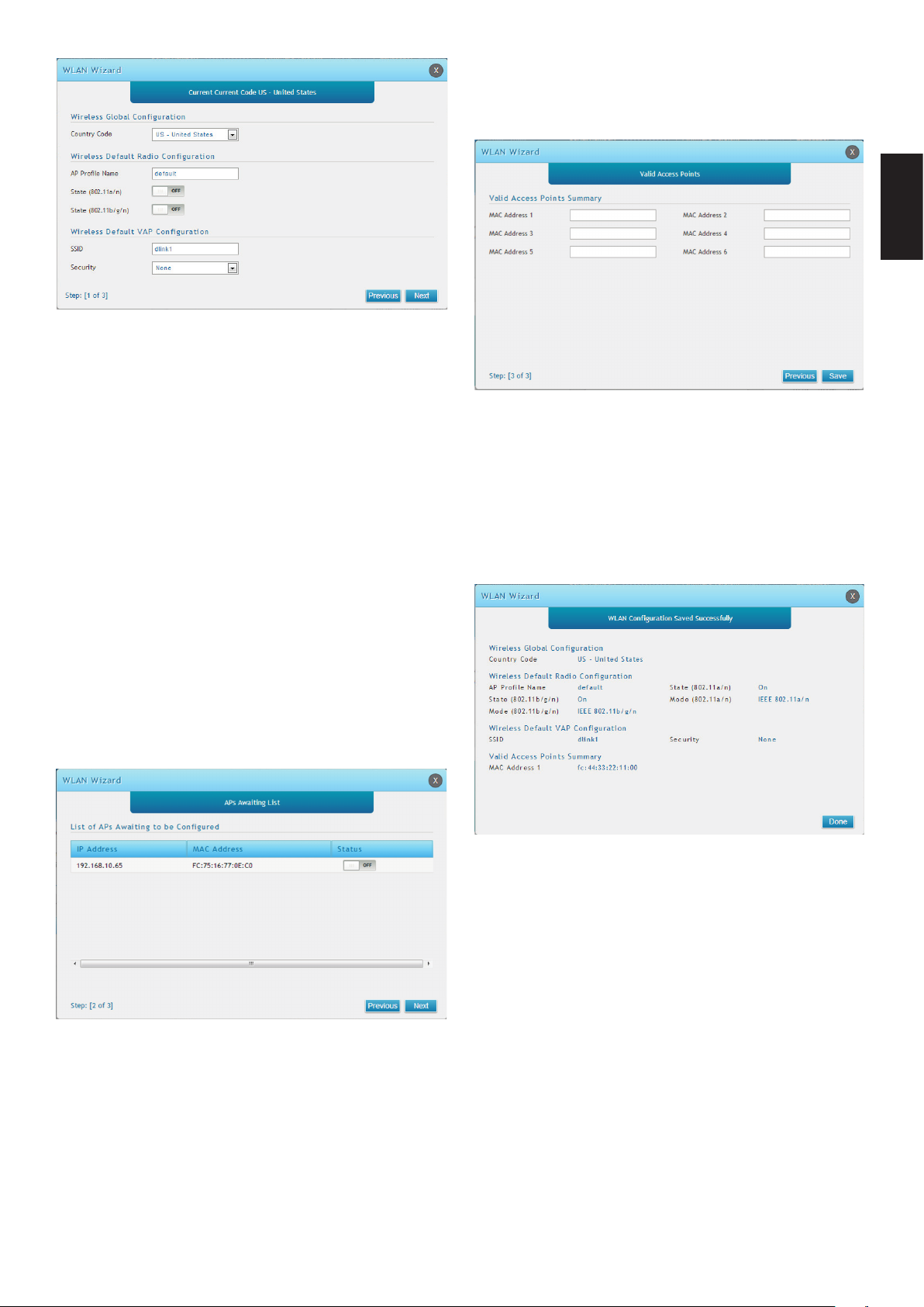
Abbildung 13. Der WLAN-Assistent
2. Es stehen Ihnen die zwei unten beschriebene
Methoden zum Hinzufügen von Access
Points zur Managed AP-Liste zur Verfügung:
Valid Access Point Summary (Gültiger Access
Point - Übersicht): Geben Sie die MACAdresse des AP ein, der verwaltet werden soll.
DEUTSCH
Abbildung 15. Eingabe der MAC-Adressen
a. List of APs Awaiting to be Congured (Liste
der zu kongurierenden APs): Wählen
Sie die Access Points, die vom Wireless
Controller automatisch erkannt werden.
b. Valid Access Point Summary (Gültiger
Access Point - Übersicht): Geben Sie die
MAC-Adresse des Access Point manuell
ein.
List of APs Awaiting to be Congured (Liste der
zu kongurierenden APs): Dies ist eine Liste
der gefundenen Access Points. Stellen Sie den
Status des AP, den Sie verwalten möchten, auf
ON (EIN).
3. Einstellungen speichern und Verbindung
herstellen - Sobald der Einrichtungsvorgang
des Assistenten für die WLAN-Verbindung
beendet ist, klicken Sie auf 'Connect'
(Verbinden), um Ihre Einstellungen zu speichern
und Ihre APS zu verbinden.
Abbildung 16. Übersicht
Abbildung 14. Konguration des AP
13
Page 14

Weitere Informationen
Weitere Informationen und Hilfe zur
Konguration des DWC-2000 nden Sie in der
Begleitdokumentation auf der im Lieferumfang
enthaltenen Master-CD oder auf der Website
http://support.dlink.com von D-Link.
• D-Link Wireless Controller -
DEUTSCH
Benutzerhandbuch
In diesem Handbuch werden die allgemeinen
Operationen und Steuerelemente der
Wireless Controller-Firmware beschrieben,
die die Hardware des Wireless Controllers
steuert. Enthalten sind Beispiele zur
Durchführung typischer administrativer
Aufgaben wie das Einrichten der Rogue
AP-Erkennung und Beispiele zur Verwendung
des Wireless Controllers in verschiedenen
Szenarien.
• D-Link Wireless Controller - CLI
Referenzhandbuch
In diesem Handbuch werden alle verfügbaren
textbasierten Befehle beschrieben, die auf
einer RJ45-zu-DB9 Konsole oder der SSH-
Schnittstelle zur Konguration des Wireless
Controllers verwendet werden können.
Online Support
Sollten Probleme aufgetreten sein, die nicht im
Benutzerhandbuch behandelt werden, besuchen
Sie bitte die Website http://support.dlink.com.
Dort werden Sie an Ihre entsprechende regionale
Support Website von D-Link weitergeleitet.
Garantiebestimmungen
Informationen zur eingeschränkten Garantie auf
Lebenszeit für Produkte von D-Link nden Sie
unter http://warranty.dlink.com/
14
14
Page 15
À Propos de ce Guide
Ce guide fournit des instructions qui vous aideront
à congurer étape par étape votre contrôleur sans
l DWC-2000 de D-Link. Notez que le modèle que
vous avez acheté peut légèrement différer de celui
illustré sur les gures.
Le contrôleur sans l DWC-2000 est un contrôleur
de réseau local sans l complet, conçu pour
les environnements réseau de taille moyenne à
grande. Le contrôleur possède toute une gamme
de fonctions de gestion et de sécurité des réseaux
et des points d'accès. Par défaut, il peut contrôler
jusqu'à 64 points d'accès et jusqu'à 256 après mise
à jour avec des packs de licence.
Le DWC-2000 peut être mis à jour avec trois packs
de licence en option :
• Les packs de licence DWC-2000-AP32/DWC-
2000-AP32-LIC permettent de gérer jusqu'à
32 points d'accès supplémentaires.
• Les packs de licence DWC-2000-AP64/DWC-
2000-AP64-LIC permettent de gérer jusqu'à
64 points d'accès supplémentaires.
• Les packs de licence DWC-2000-AP128/
DWC-2000-AP128-LIC permettent de gérer
jusqu'à 128 points d'accès supplémentaires.
Élé-
ment
A
B Voyant d'alimentation
C Voyant du ventilateur
D Ports USB (1-2)
E
F
G
H Port de console
I Bouton Marche/Arrêt
J Prise de courant
Composant Description
Bouton de
réinitialisation
Emplacement de
module de disque dur
Ports LAN Gigabit SFP
(1-4)
Ports LAN Gigabit
RJ-45 (1-4)
Réinitialisation du
système
Indique si le contrôleur
sans l est sous tension
Indique l'état du
ventilateur du contrôleur
sans l
Ces ports peuvent
prendre en charge
différents périphériques
USB 1.1 ou 2.0.
Emplacement pour le
module de disque dur
Connexion aux
périphériques Ethernet
tels que des ordinateurs,
des commutateurs et des
concentrateurs.
Connexion aux
périphériques Ethernet
tels que des ordinateurs,
des commutateurs et des
concentrateurs.
Permet d'accéder à
l'interface de ligne de
commande (CLI) via un
câble de console RJ-45 à
DB-9
Allume/éteint le
périphérique
Permet de connecter le
cordon d'alimentation
FRANÇAIS
Le DWC-2000 peut être mis à jour plusieurs fois
avec des packs de licences, permettant la prise en
charge d'un maximum de 256 points d'accès.
Présentation du produit
ABCD E
Figure 1. Façade
F G H
Voyants d'état et voyants des ports
Ethernet
Connexion
Vitesse
Figure 3. Voyants du port Ethernet RJ-45
Vitesse de liaison
et état d'émission/
réception
Figure 4. Voyants du port Ethernet SFP
Le tableau suivant répertorie le nom, la couleur,
l'état et la description de chaque voyant du
périphérique.
État d'émission/réception
Figure 2. Panneau arrière
I
J
15
15
Page 16

Voyant
lumineux
Alimentation/
État
Ventilateur Vert/rouge Vert xe Le ventilateur
FRANÇAIS
USB Vert Vert xe La connexion est
État
d'émission/
réception du
port RJ-45
Vitesse de
liaison du port
RJ-45
Liaison et
émission/
réception du
port SFP
Couleur État Description
Orange/
Vert
Vert Vert xe Une connexion est
Vert/
Orange
Vert/
Orange
Orange xe Processus de mise
Vert xe Processus de
mise sous tension
Orange
clignotant
Voyant éteint Le périphérique est
Rouge xe Le ventilateur est en
Vert clignotant Ce port présente
Voyant éteint Pas de liaison.
Vert clignotant Le port envoie ou
reçoit des données.
Voyant éteint Pas de liaison.
Vert xe Le port fonctionne à
Orange xe Le port fonctionne à
Voyant éteint Le port fonctionne à
Vert xe Le port fonctionne à
Vert clignotant Le port envoie ou
reçoit des données
Orange xe Le port fonctionne à
Orange
clignotant
Le port envoie ou
reçoit des données
Paramètres par défaut de l'interface
sous tension en
cours.
terminé.
Le périphérique
a planté et est
en mode de
récupération.
éteint.
fonctionne
normalement.
panne.
correcte.
une activité.
active.
100 Mbits/s.
1000 Mbits/s.
10 Mbits/s.
100 Mbits/s.
à 100 Mbits/s.
1000 Mbits/s.
à 1000 Mbits/s.
Avant de commencer
Respectez les précautions suivantes an d'éviter
tout risque d'arrêt, de dysfonctionnement de
l'équipement ou de blessure :
• Avant l'installation, vériez toujours que
l'alimentation est déconnectée.
• Vériez que la pièce dans laquelle le
périphérique est utilisé est correctement aérée
et que la température ambiante ne dépasse
pas 40 °
• Veillez à laisser au moins un mètre devant et
derrière le périphérique.
• Si vous installez l'appareil dans un rack,
veillez à ce que le cadre de ce dernier ne
bouche pas les orices de ventilation de
l'appareil. Assurez-vous que les racks intégrés
possèdent des ventilateurs et des orices
latéraux.
• Assurez-vous qu'aucune des conditions
dangereuses suivantes n'est présente avant
l'installation : sols humides ou mouillés, fuites,
câbles d'alimentation non reliés à la terre
ou endommagés ou usés, ou absence des
bornes de mise à la terre.
Étape 1 - Déballage
Ouvrez le carton d'emballage et déballez
soigneusement son contenu. Consultez la liste
de colisage ci-dessous pour vous assurer qu'il ne
manque aucun article et qu'ils sont tous en bon état.
Si un des éléments est manquant ou endommagé,
veuillez contacter votre revendeur D-Link local
pour obtenir un remplacement.
Interface
Ethernet
LAN (1-4) IP statique 192.168.10.1/24 Activé
Type
d'interface
IP Address
(Adresse IP) :
Gestion Web
Installation et connexion
Cette section décrit comment installer un
DWC-2000 dans un rack standard de 19 pouces
et comment y relier des câbles et l'alimentation.
16
Contenu de la boîte
Contrôleur sans l DWC-2000 1
Cordon d'alimentation 1
Câble de console
(câble RJ-45 à DB-9)
Câble Ethernet
(CAT5 UTP/droit)
CD de référence 1
Supports de montage en rack 2
Pack de vis 1
Guide d'installation rapide 1
1
1
Page 17

Étape 2 - Installation
Vous pouvez monter le DWC-2000 dans un
rack standard de 19 pouces. Pour installer le
DWC-2000 dans un rack :
1. Montez les supports de montage de chaque
côté du châssis comme indiqué sur la Figure 5,
puis xez-les à l'aide des vis fournies.
Fan
Figure 5. Supports de xation
2. Utilisez les vis fournies avec le bâti pour monter
le périphérique dedans, comme illustré à la
Figure 6.
FRANÇAIS
Figure 7. Connexion au réseau
1. Connectez un câble RJ-45 entre l'un des ports
étiquetés LAN (1-4) et un commutateur de la
section de réseau LAN.
2. Connectez un câble RJ-45 à DB-9 entre le port
de console et une station de travail pour utiliser
l'interface CLI (interface de ligne de commande)
pour la gestion.
Étape 4 - Mise sous tension du
Fan
Figure 6. Montage dans le rack
Étape 3 - Connexion du
périphérique à un réseau
Cette section fournit des informations de base sur
la connexion physique du DWC-2000 à un réseau.
périphérique
Le cordon d'alimentation CA fourni avec l'appareil
permet de relier ce dernier à la terre lorsqu'il est
branché à une prise de courant CA reliée à la terre.
Le périphérique doit être relié à la terre pendant
son fonctionnement normal.
Pour connecter le périphérique à une source
d'alimentation, branchez une extrémité du
cordon CA au connecteur d'alimentation CA situé
à l'arrière de l'appareil. Branchez l'autre extrémité
dans une prise de courant et allumez l'interrupteur
d'alimentation.
Remarque : Nous recommandons d'utiliser un
parasurtenseur pour la connexion de l'alimentation.
Connectez les câbles nécessaires comme illustré
en Figure 7.
17
Page 18

Conguration initiale
Le logiciel du contrôleur sans l est préinstallé
sur le DWC-2000. Une fois le périphérique
allumé, il est prêt à être conguré. Il est fourni
avec une conguration d'usine par défaut qui
vous permet d'établir une connexion, mais vous
devez congurer le contrôleur pour satisfaire
aux besoins spéciques de votre réseau.
Figure 8. Utilisation du navigateur
4. Ouvrez une session dans l'interface Web
du contrôleur sans l. Par défaut, les
informations d'ouverture de session sont
les suivantes :
Détection du contrôleur sans l
Utilisation de l'interface Web
FRANÇAIS
Pour utiliser l'interface Web, la station de
travail qui sert à gérer le périphérique doit se
trouver initialement sur le même sous-réseau
que celui-ci. Vous aurez également besoin d'un
navigateur compatible :
Navigateur Version minimale
Microsoft
Internet Explorer
Mozilla Firefox 23
Apple Safari
Google Chrome 26
9, 10
iOS : 6.1.3
Windows : 5.1.7
• Username (Nom d’utilisateur) : admin
• Mot de passe : admin
Figure 9. Page d'ouverture de session
Connexion via la console (ETCD RJ-45 à
DB-9)
Le contrôleur sans l DWC-2000 dispose d'un
port série vous permettant de vous connecter à
un ordinateur ou un terminal an de surveiller
et congurer le périphérique. Ce port utilise un
connecteur RJ-45, permettant de réaliser une
connexion ETCD (Équipement Terminal de
Circuit de Données).
Pour accéder à l'interface Web du périphérique :
1. Connectez votre poste de travail à l'un des
ports étiquetés LAN (1-4).
2. Assurez-vous que le poste de travail est
conguré avec une adresse IP statique
dans le sous-réseau 192.168.10.0/24.
Remarque : Pour éviter des problèmes,
désactivez tout logiciel de blocage des
fenêtres publicitaires ou ajoutez l'adresse IP
de gestion http://192.168.10.1 à la liste des
sites autorisés du bloqueur de fenêtres
publicitaires.
3. Lancez votre navigateur, puis saisissez
l'adresse IP de l'interface du réseau
local (l'adresse IP par défaut est
http://192.168.10.1), puis appuyez sur Enter
(Entrée).
Pour utiliser la connexion du port de console,
vous avez besoin du matériel suivant :
1. Un terminal ou un ordinateur possédant à la
fois un port série et la capacité d'émuler un
terminal.
2. Le câble RJ-45 à DB-9 inclus.
3. Si votre ordinateur portable ou votre PC
ne possède pas de connecteur RS-232, un
convertisseur (non fourni) est nécessaire.
Pour établir une connexion de console :
1. Branchez le connecteur RJ-45 du câble
RJ-45 à DB-9 fourni directement dans le
port de la console du contrôleur sans l.
2. Connectez l'autre extrémité du câble à
un terminal ou à un connecteur série d'un
18
Page 19

ordinateur exécutant un logiciel d'émulation
de terminal. Congurez les valeurs du
logiciel d'émulation du terminal de la façon
suivante :
• Débit de baud : 115200
• Bits de données : 8
• Parité : Aucun
• Bits d'arrêt : 1
• Contrôle de ux : Aucun
3. Connectez le contrôleur sans l suivant
les instructions de la section « Mise sous
tension du périphérique » de ce guide. La
séquence de démarrage apparaît sur le
terminal.
4. Une fois la séquence de démarrage
terminée, l'invite de commande s'afche et
le périphérique est prêt à être conguré.
Détection et gestion du PA unié
4. Exécutez l'Assistant pour gérer vos points
d'accès. Cliquez sur « Wizard » (Assistant)
dans le coin supérieur droit.
Figure 11. Assistant
5. Cliquez sur le bouton « Run… » (Exécuter...)
pour exécuter l'Assistant du réseau local
sans l.
Figure 12. Exécuter l'Assistant du réseau local sans
l
1. Saisissez les informations suivantes pour
compléter l'Assistant de conguration
du réseau local sans l :
FRANÇAIS
Internet
Routeur/
Serveur
DHCP
Réseau
local
Commutateur
Réseau local
Point
d'accès
unié
Figure 10. Topologie de réseau
DWC-2000
Pour détecter et gérer le PA unié :
1. Enregistrez l'adresse MAC de chaque PA
unié sur le réseau.
• Conguration globale sans l : Choisissez
le code pays.
• Conguration par défaut de la carte
réseau sans l : Créez un Prol de PA
correspondant au paramètre de la carte
réseau sans l. Dénissez le mode Carte
réseau sans l de chaque carte.
• Conguration par défaut du VAP sans
l : Saisissez le nom de réseau du
SSID, puis sélectionnez une méthode
de sécurité. Si vous sélectionnez WEP
statique ou WPA personnel, saisissez un
mot de passe sécurisé pour votre réseau
local sans l.
2. Connectez le PA unié que vous voulez
congurer sur le réseau Ethernet local.
3. Connectez-vous au DWC-2000 et dénissez
l'adresse IP du réseau local pour accéder
au sous-réseau du réseau Ethernet local.
Figure 13. Assistant du réseau local sans l
19
Page 20

2. Vous trouverez ci-dessous deux
méthodes pour ajouter des points
d'accès dans la liste des PA gérés :
a. Liste des PA en attente d'être congurés :
Sélectionnez les points d'accès qui
sont détectés automatiquement par le
contrôleur sans l.
b. Récapitulatif des points d’accès valides :
Saisissez l'adresse MAC du point d'accès
manuellement.
Liste des PA en attente d'être congurés : Il
FRANÇAIS
s'agit de la liste des points d'accès détectés.
Faites passer l'état du point d'accès que
vous souhaitez gérer sur ON (Activé).
Informations
Figure 16. Résumé
complémentaires
Vous pouvez consulter la documentation
complémentaire proposée sur le CD principal
joint ou visiter le site http://support.dlink.com
pour obtenir plus d'aide sur la conguration de
votre DWC-2000.
• Manuel d'utilisation du contrôleur sans
l D-Link
Ce manuel explique comment
faire fonctionner et commander le
microprogramme du contrôleur sans l qui
gère et commande le matériel du contrôleur
Figure 14. Conguration du PA
Récapitulatif des points d’accès valides :
Saisissez l'adresse MAC du PA que vous
souhaitez gérer.
sans l. Il comporte des exemples de
réalisation de tâches administratives types,
telles que la conguration d'une détection de
PA indésirables et l'utilisation du contrôleur
sans l dans diverses situations.
Figure 15. Saisie des adresses MAC
3. Enregistrez les paramètres et connectezvous - Lorsque l'Assistant de conguration
de connexion au réseau local sans l
a été exécuté, cliquez sur le bouton
Connect (Connexion) pour enregistrer vos
paramètres et connecter vos PA.
20
• Guide de référence du CLI du contrôleur
sans l de D-Link
Ce document présente toutes les
commandes textuelles disponibles que
vous pouvez utiliser sur une console RJ-45
à DB-9 ou sur une interface SSH pour
congurer le contrôleur sans l.
Assistance en ligne
Si vous rencontrez des problèmes non
répertoriés dans le manuel d'utilisation,
consultez le site http://support.dlink.com, qui
vous renverra vers votre site Web de support
D-Link local approprié.
Informations sur la garantie
Les informations relatives à la garantie limitée
dans le temps D-Link sont disponibles à
l’adresse suivante : http://warranty.dlink.com/
Page 21

Acerca de esta guía
Esta guía ofrece instrucciones paso a paso para
congurar el controlador inalámbrico D-Link
DWC-2000. Tenga en cuenta que el modelo que
ha adquirido puede tener un aspecto ligeramente
diferente al mostrado en las ilustraciones.
El controlador inalámbrico DWC-2000 es
un controlador LAN inalámbrico totalmente
equipado para entornos de red de tamaño
mediano a grande. El controlador tiene una
serie de funciones para la gestión de red y del
punto de acceso, puede controlar de forma
predeterminada hasta 64 puntos de acceso y
hasta 256 con actualizaciones del paquete de
licencia.
El DWC-2000 se puede actualizar con tres
paquetes de licencia opcionales:
• Los paquetes de licencia DWC-2000-AP32/
DWC-2000-AP32-LIC permiten gestionar
hasta 32 puntos de acceso adicionales.
• Los paquetes de licencia DWC-2000AP64/DWC-2000-AP64-LIC permiten
gestionar hasta 64 puntos de acceso
adicionales.
Elemento Pieza Descripción
A Botón de reinicio
B
C
D
E
F
G
H
I
J
LED de
alimentación
LED del
ventilador
Puertos USB
(1-2)
Bahía para
módulo de unidad
de disco duro
Puertos Gigabit
SFP de LAN (1-4)
Puertos Gigabit
RJ-45 de LAN
(1-4)
Puerto de la
consola
Interruptor de
alimentación
Toma de
alimentación
Reiniciar el sistema
Indica si el controlador
inalámbrico está
encendido.
Indica el estado del
ventilador en el controlador
inalámbrico
Estos puertos pueden
admitir diversos
dispositivos USB 1.1 o 2.0
Bahía para el módulo de la
unidad de disco duro
Para conectarse a
dispositivos Ethernet
como ordenadores,
conmutadores y terminales
Para conectarse a
dispositivos Ethernet
como ordenadores,
conmutadores y terminales
Se utiliza para acceder
a la interfaz de línea de
comandos (CLI) a través
de un cable para consola
de RJ-45 a DB-9
Enciende y apaga el
dispositivo
Se conecta al cable de
alimentación
ESPAÑOL
• Los paquetes de licencia DWC-2000AP128/DWC-2000-AP128-LIC permiten
gestionar hasta 128 puntos de acceso
adicionales.
El DWC-2000 se puede actualizar varias veces
con paquetes de licencia que permiten admitir
hasta un máximo de 256 puntos de acceso.
Descripción general del
producto
ABCD E
Figura 1. Panel frontal
F G H
Indicadores LED de estado e
indicadores LED de puerto Ethernet
Figura 3. Indicadores LED de puerto Ethernet RJ-45
Velocidad
de la conexión
Figura 4. Indicadores LED de puerto Ethernet SFP
Velocidad de la
conexión y estado
de transmisión/
recepción
La tabla siguiente enumera el nombre, el color,
el estado y la descripción de cada LED del
dispositivo.
Estado de
transmisión/recepción
Figura 2. Panel posterior
I
J
21
Page 22

Indicador
LED
Alimentación/
estado
Ventilador Verde/
USB Verde Verde
Color Estado Descripción
Naranja/
verde
rojo
ESPAÑOL
Estado de
transmisión/
recepción del
puerto RJ-45
Velocidad de
conexión del
puerto RJ-45
Conexión y
transmisión/
recepción del
puerto SFP
Verde Verde
Verde/
naranja
Verde/
naranja
Conguración de interfaz
predeterminada
Naranja
continuo
Verde
continuo
Naranja
parpadeante
Luz apagada El dispositivo está
Verde
continuo
Rojo continuo El ventilador ha
continuo
Verde
parpadeante
Luz apagada No existe conexión.
continuo
Verde
parpadeante
Conexión
apagada
Verde
continuo
Naranja
continuo
Luz apagada El puerto funciona a
Verde
continuo
Verde
parpadeante
Naranja
continuo
Naranja
parpadeante
Proceso de
encendido en
curso.
Proceso de
encendido
completo.
El dispositivo se
ha bloqueado y
está en modo de
recuperación.
apagado.
El ventilador
funciona
correctamente.
fallado.
La conexión es
buena.
Existe actividad en
este puerto.
Existe conexión.
El puerto está
enviando o
recibiendo datos.
No existe conexión.
El puerto funciona a
100 Mbps.
El puerto funciona a
1.000 Mbps.
10 Mbps.
El puerto funciona a
100 Mbps.
El puerto está
enviando o
recibiendo datos a
100 Mbps.
El puerto funciona a
1.000 Mbps.
El puerto está
enviando o
recibiendo datos a
1.000 Mbps.
Instalación y conexión
En esta sección se describe cómo instalar un
DWC-2000 en un estante de equipos estándar
de 19 pulgadas y cómo conectar los cables y la
alimentación al dispositivo.
Antes de empezar
Respete las precauciones siguientes para
ayudar a evitar paradas, errores del equipo y
lesiones:
• Antes de la instalación, compruebe
siempre que la fuente de alimentación está
desconectada.
• Asegúrese de que la sala en la que utiliza
el dispositivo tiene la circulación de aire
adecuada y que la temperatura de la sala
no supera los 40 °C (104 °F).
• Asegúrese de que hay un metro (tres pies)
de espacio como mínimo en la parte frontal
y en la parte trasera del dispositivo.
• No coloque el dispositivo en una estructura
de estante de equipos que bloquee la
ventilación de aire en los laterales del
chasis. Asegúrese de que los estantes
adjuntos tienen ventiladores y laterales con
celosía.
• Antes de la instalación, asegúrese de
que no existe ninguna de las condiciones
peligrosas siguientes: suelos húmedos o
con agua, fugas, cables de alimentación sin
toma de tierra o falta de tomas de tierra de
seguridad.
Paso 1 – Desempaquetado
Abra la caja del envío y desempaquete su
contenido con cuidado. Consulte la lista de
envasado siguiente para asegurarse de que
todos los artículos están presentes y que no
están dañados. Si falta algún artículo o está
dañado, póngase en contacto con su proveedor
local de D-Link para que lo reponga.
Interfaz
Ethernet
LAN (1-4) IP estática 192.168.10.1/24 Activado
Tipo de
interfaz
Dirección IP Gestión
basada en
22
web
¿Qué contiene la caja?
DWC-2000 Wireless Controller 1
Cable de alimentación 1
Page 23

Cable para consola
(cable RJ-45 a DB-9)
Cable Ethernet
(CAT5 UTP/directo)
CD de referencia 1
Paso 3 – Conexión del
1
dispositivo a una red
1
Esta sección proporciona información
básica acerca de la conexión física entre el
DWC-2000 y una red.
Soportes de montaje en estante 2
Paquete de tornillos 1
Guía de instalación rápida 1
Paso 2 – Instalación
Puede montar el DWC-2000 en un estante de
equipos estándar de 19 pulgadas. Para instalar el
DWC-2000 en un estante:
1. Acople los soportes de montaje a cada lado
del chasis, como se muestra en la gura 5
y fíjelos con los tornillos suministrados.
Conecte los cables necesarios como se muestra
en la gura 7.
ESPAÑOL
Figura 7. Conectando con la red
1. Conecte un cable RJ-45 desde uno de
los puertos con la etiqueta LAN (1-4) a un
conmutador en el segmento de red LAN.
Fan
Figura 5. Soportes de montaje
2. Utilice los tornillos suministrados con el estante
de equipos para montar el dispositivo en
el estante como se muestra en la gura 6.
Fan
Figura 6. Montaje en el estante
2. Conecte un cable de RJ-45 a DB-9 desde
el puerto de la consola a una estación de
trabajo para utilizar CLI (Interfaz de línea de
comandos) para la gestión.
Paso 4 – Encendido del
dispositivo
El cable de alimentación CA enviado con el
dispositivo conecta el dispositivo a la toma
de tierra cuando se enchufa en una toma
de alimentación CA conectada a tierra. El
dispositivo debe estar conectado a tierra durante
el funcionamiento normal.
Para conectar el dispositivo a una fuente de
alimentación, enchufe un extremo del cable de
alimentación CA en el conector de alimentación
de CA en el panel posterior del dispositivo.
Enchufe el otro extremo a una toma eléctrica y
ENCIENDA el interruptor de alimentación.
Nota: se recomienda el uso de un protector de
sobretensión para la conexión de alimentación.
23
Page 24

Conguración inicial
El software del controlador inalámbrico está
preinstalado en el DWC-2000. Cuando se enciende
el dispositivo, está preparado para congurarse.
Se envía con una conguración predeterminada
de fábrica que permite conectarse al mismo,
aunque deberá congurar el controlador para sus
requisitos de red especícos.
Descubrir el controlador
inalámbrico
Utilización de la interfaz de usuario web
Para utilizar la interfaz de usuario web, la estación
de trabajo desde la que gestiona el dispositivo
ESPAÑOL
debe estar inicialmente en la misma subred que
el dispositivo. También necesitará un explorador
compatible:
Explorador Versión mínima
Microsoft
Internet Explorer
Mozilla Firefox 23
Apple Safari
9, 10
iOS: 6.1.3
Windows: 5.1.7
Figura 8. Utilización del explorador
4. Inicie sesión en la interfaz de web del controlador
inalámbrico. La información predeterminada de
inicio de sesión es:
• Nombre de usuario: admin
• Contraseña: admin
Figura 9. Página de inicio de sesión
Conexión a través de la consola (DCE de
RJ-45 a DB-9)
El controlador inalámbrico DWC-2000 incluye un
puerto serie que permite conectarse a un ordenador
o terminal para la monitorización y conguración
del dispositivo. Este puerto es un conector RJ-45
y se utiliza como una conexión de equipo terminal
de comunicación de datos (DCE).
Google Chrome 26
Para acceder a la interfaz de usuario web del
dispositivo:
1. Conecte la estación de trabajo a uno de los
puertos con la etiqueta LAN (1-4).
2. Asegúrese de que la estación de trabajo está
congurada con una dirección IP estática en la
subred 192.168.10.0/24.
Nota: para evitar problemas, desactive
cualquier software de bloqueo de elementos
emergentes o añada la dirección IP de gestión
http://192.168.10.1 a la lista de sitios permitidos.
3. Inicie el explorador e introduzca la dirección
IP de la interfaz de LAN (la dirección IP
predeterminada es http://192.168.10.1); a
continuación, pulse Intro.
Para utilizar la conexión del puerto de la
consola, necesita el equipo siguiente:
1. Un terminal o un ordenador con un puerto serie
y capacidad para emular un terminal.
2. El cable de RJ-45 a DB-9 incluido.
3. Si su ordenador portátil o de sobremesa no
tiene un
conector RS-232, será necesario un
convertidor (no incluido).
Para establecer una conexión de consola:
1. Enchufe directamente el extremo del conector
RJ-45 del cable de RJ-45 a DB-9 suministrado
al puerto para consola en el controlador
inalámbrico.
24
Page 25

2. Conecte el otro extremo del cable a un terminal
o al conector serie de un ordenador que ejecute
el software de emulación de terminal. Congure
los valores del software de emulación de
terminal del modo siguiente:
• Frecuencia de baudios: 115.200
• Bits de datos: 8
• Paridad: Ninguno
• Bits de parada: 1
• Control de ujo: Ninguno
3. Conecte el controlador inalámbrico siguiendo
las instrucciones de la sección “Encendido
del dispositivo” de esta guía. En el terminal se
mostrará la secuencia de arranque.
4. Una vez completada la secuencia de arranque,
se mostrará el símbolo del sistema y el
dispositivo está preparado para congurarse.
3. Inicie sesión en el DWC-2000 y establezca
la dirección IP de LAN para que esté en la
subred de la red Ethernet de área local.
4. Siga el asistente para gestionar los puntos
de acceso. Haga clic en “Asistente” en la
esquina superior derecha.
Figura 11. Asistente
5. Haga clic en el botón “Ejecutar…” para
ejecutar el asistente de WLAN.
ESPAÑOL
Descubrir y gestionar el AP
unicado
Internet
Router/
servidor
DHCP
LAN
Conmutador
LAN
Punto de
acceso
unicado
DWC-2000
Figura 12. Ejecutar el asistente de WLAN
1. Introduzca la información siguiente
para completar el Asistente para la
conguración de WLAN:
• Conguración global inalámbrica: elija el
código de país.
• Conguración de radio inalámbrica
predeterminada: cree un perl de AP
para la conguración de radio de la red
inalámbrica. Establezca el modo de
radio para cada radio.
• Conguración de VAP inalámbrico
predeterminado: introduzca el nombre de
red SSID y, a continuación, seleccione un
método de seguridad. Si selecciona WEP
estático o WPA Personal, introduzca una
frase secreta segura para la WLAN.
Figura 10. Topología de la red
Para descubrir y gestionar el AP unicado:
1. Registre la dirección MAC de cada AP unicado
en la red.
2. Conecte el AP unicado que desea congurar
a la red Ethernet de área local.
25
Page 26

Figura 13. Asistente de WLAN
Figura 15. Introducir las direcciones MAC
2. A continuación se muestran dos métodos
para añadir puntos de acceso a la lista
de AP gestionados:
a. Lista de los AP que esperan para ser
ESPAÑOL
congurados: seleccione los puntos de
acceso que el controlador inalámbrico
descubre automáticamente.
b. Resumen de punto de acceso válido:
introduzca la dirección MAC del punto
de acceso de forma manual.
Lista de los AP que esperan para ser
congurados: esta es una lista de los puntos
de acceso detectados. Cambie el estado
del punto de acceso que desea gestionar a
ACTIVADO.
3. Guardar parámetros y conectar: una
vez completado el asistente para la
conguración de la conexión WLAN, haga
clic en el botón Conectar para guardar los
parámetros y conectar los AP.
Figura 16. Resumen
Figura 14. Congurar el AP
Resumen de punto de acceso válido:
introduzca la dirección MAC del AP que
desea gestionar.
26
Información adicional
Puede consultar la documentación adicional que
encontrará en el CD maestro incluido o visitar
en línea la página http://support.dlink.com para
obtener más asistencia sobre cómo congurar
el DWC-2000.
• Manual del usuario del controlador
inalámbrico D-Link
Este manual describe el funcionamiento y
control general del rmware del controlador
inalámbrico que activa y controla el
hardware del controlador inalámbrico.
Incluye ejemplos sobre cómo llevar a cabo
las tareas administrativas normales como,
por ejemplo, congurar una detección de AP
deshonesta y cómo utilizar el controlador
inalámbrico en diversas situaciones.
Page 27

• Guía de referencia CLI del controlador
inalámbrico D-Link
Este documento describe todos los
comandos de texto disponibles que se
pueden utilizar en una
consola RJ-45 a DB-9 o interfaz SSH para
congurar el controlador inalámbrico.
Soporte técnico en línea
Si surgen problemas que no aparecen en el
manual de usuario, visite el sitio http://support.
dlink.com, que le dirigirá al sitio web local de
soporte de D-Link correspondiente.
Información acerca de la garantía
La información sobre la Garantía limitada de
D-Link está disponible en http://warranty.dlink.
com/
ESPAÑOL
27
Page 28

Informazioni sulla guida
La presente guida contiene istruzioni passo-passo
per la congurazione del controller wireless D-Link
DWC-2000. Notare che il modello acquistato
potrebbe essere leggermente diverso da quello
rafgurato nelle illustrazioni.
DWC-2000 Wireless Controller è un controller
LAN wireless progettato per ambienti di rete di
dimensioni medio-grandi. Il controller include una
vasta gamma di funzioni per la gestione della rete e
dei punti di accesso. Per impostazione predenita
può controllare no a 64 punti di accesso, che
diventano 256 se si dispone di aggiornamenti con
pacchetto licenza.
L'aggiornamento del controller DWC-2000 può
essere effettuato utilizzando tre pacchetti licenza
facoltativi:
• I pacchetti licenza DWC-2000-AP32/DWC-
2000-AP32-LIC consentono di gestire no a
32 ulteriori punti di accesso.
ITALIANO
• I pacchetti licenza DWC-2000-AP64/DWC-
2000-AP64-LIC consentono di gestire no a
64 ulteriori punti di accesso.
Elemento Parte Descrizione
A Pulsante di reset
B
C LED della ventola
D Porte USB (1-2)
E
F
G
H Porta per console
I
J Presa elettrica
LED di
alimentazione
Slot modulo unità
disco rigido
Porte SFP LAN
Gigabit (1-4)
Porte RJ-45 LAN
Gigabit (1-4)
Interruttore di
alimentazione
Reset sistema
Indica se il controller
wireless è acceso
Indica lo stato della ventola
del controller wireless
Possono supportare diversi
dispositivi USB 1.1 o 2.0
Slot per il modulo dell'unità
disco rigido
Utilizzate per la
connessione a dispositivi
Ethernet, ad esempio
computer, switch e hub
Utilizzate per la
connessione a dispositivi
Ethernet, ad esempio
computer, switch e hub
Utilizzata per accedere
all'interfaccia della riga di
comando (Command Line
Interface, CLI) tramite il
cavo per console da RJ-45
a DB-9
Consente di accendere/
spegnere il dispositivo
Utilizzata per il
collegamento del cavo di
alimentazione
• I pacchetti licenza DWC-2000-AP128/
DWC-2000-AP128-LIC consentono di gestire
no a 128 ulteriori punti di accesso.
Il dispositivo DWC-2000 può essere aggiornato più
volte con pacchetti licenza, offrendo il supporto per
un massimo di 256 punti di accesso.
Panoramica sul prodotto
ABCD E
Figura 1. Pannello frontale
F G H
LED di stato e LED delle porte Ethernet
Velocità
Velocità
Figura 3. LED della porta RJ-45 Ethernet
Velocità col-
legamento e
stato TX/RX
Figura 4. LED della porta SFP Ethernet
Stato
TX/RX
28
Figura 2. Pannello posteriore
Nella seguente tabella sono elencati il nome, il
colore, lo stato e la descrizione di tutti i LED del
dispositivo.
I
J
Page 29

Indicatore
LED
Accensione/
Stato
Ventola Verde/
USB Verde Verde sso Collegamento
Stato TX/RX
della porta
RJ-45
Stato
collegamento
della porta
RJ-45
Collegamento
e TX/RX della
porta SFP
Colore Stato Descrizione
Arancione/
Verde
Rosso
Verde Verde sso Collegamento
Verde/
Arancione
Verde/
Arancione
Arancione
sso
Verde sso Processo di
Arancione
lampeggiante
Spia spenta Il dispositivo è
Verde sso La ventola
Rosso sso La ventola non
Verde
lampeggiante
Spia spenta Collegamento
Verde
lampeggiante
Spia
collegamento
spenta
Verde sso La porta funziona
Arancione
sso
Spia spenta La porta funziona
Verde sso La porta funziona
Verde
lampeggiante
Arancione
sso
Arancione
lampeggiante
Processo di
accensione in
accensione
completato.
Il dispositivo si è
arrestato in modo
anomalo e si trova
in modalità di
ripristino.
spento.
funziona
normalmente.
funziona.
corretto.
Attività sulla porta.
assente.
presente.
La porta invia o
riceve dati.
Collegamento
assente.
a 100 Mbps.
La porta funziona
a 1000 Mbps.
a 10 Mbps.
a 100 Mbps.
La porta invia o
riceve dati a 100
La porta funziona
a 1000 Mbps.
La porta invia o
riceve dati a 1000
corso.
Mbps.
Mbps.
Prima di iniziare
Per prevenire arresti, malfunzionamenti del
dispositivo e lesioni, osservare le precauzioni
descritte di seguito.
• Prima dell'installazione, vericare sempre che
il cavo di alimentazione sia scollegato.
• Vericare che l'ambiente di installazione del
dispositivo abbia una sufciente ventilazione e
che la temperatura non superi i 40 ˚C (104 ˚F).
• Vericare che anteriormente e posteriormente
al dispositivo vi sia uno spazio libero di almeno
un metro (tre piedi).
• Non collocare il dispositivo in un rack che
blocchi le prese d'aria poste sui lati del telaio.
Vericare che i rack chiusi siano dotati di
ventole e lati con prese d'aria.
• Prima dell'installazione vericare che non
sussista alcuna delle seguenti condizioni di
pericolo: pavimenti bagnati o umidi, perdite,
cavi di alimentazione non collegati a terra o
logorati oppure mancanza di connessioni a
terra di sicurezza.
Passo 1 - Disimballaggio
Aprire la confezione e disimballarne il contenuto
prestando particolare attenzione. Vericare il
contenuto sulla base dell'apposito elenco riportato
di seguito per accertarsi che tutti gli articoli
siano presenti e integri. Se un articolo manca
o è danneggiato, chiederne la sostituzione al
rivenditore D-Link di zona.
Contenuto della confezione
Controller wireless DWC-2000 1
ITALIANO
Impostazioni predenite dell'interfaccia
Interfaccia
Ethernet
LAN (1-4) IP statico 192.168.10.1/24 Abilitato
Tipo di
interfaccia
Indirizzo IP Gestione
basata sul
Web
Installazione e collegamento
In questa sezione viene descritto come installare
un dispositivo DWC-2000 in un rack standard da
19 pollici e come collegare i cavi e l'alimentazione
al dispositivo.
Cavo di alimentazione 1
Cavo per connessione tramite console
(cavo da RJ-45 a DB-9)
Cavo Ethernet
(CAT5 UTP/dritto)
CD di riferimento 1
Staffe per il montaggio in rack 2
Bustina con viti 1
Guida di installazione rapida 1
1
1
29
Page 30

Passo 2 - Installazione
È possibile montare il dispositivo DWC-2000 in
un rack standard da 19 pollici. Per installare il
dispositivo DWC-2000 in un rack:
1. Collegare le staffe di montaggio su ciascun
lato del telaio, come illustrato nella Figura
5 e ssarle utilizzando le viti in dotazione.
Fan
Figura 5. Staffe per il montaggio
2. Utilizzare le viti in dotazione con il rack, per
ITALIANO
montare il dispositivo nel rack come indicato
nella Figura 6.
Figura 7. Connessione alla rete
1. Collegare con un cavo RJ-45 una delle porte
contrassegnate LAN (1-4) a uno switch nel
segmento di rete LAN.
2. Collegare con un cavo da RJ-45 a DB-9 la
porta della console a una workstation per
utilizzare l'interfaccia CLI (Command Line
Interface) per la gestione.
Passo 4 - Accensione del
Fan
Figura 6. Montaggio nel rack
Passo 3 - Collegamento del
dispositivo in rete
In questa sezione vengono fornite informazioni
di base sul collegamento sico del controller
DWC-2000 a una rete.
dispositivo
Il cavo di alimentazione CA fornito in dotazione,
collega il dispositivo con la messa a terra se
inserito in una presa CA collegata a terra.
Durante il normale funzionamento il dispositivo
deve essere collegato a terra.
Per collegare il dispositivo all'alimentazione,
inserire un'estremità del cavo di alimentazione
CA nella presa di alimentazione CA posta sul
pannello posteriore. Collegare l'altra estremità
a una presa elettrica e posizionare su ON
l'interruttore di accensione.
Nota: si consiglia l'uso di un dispositivo di
protezione da sovratensioni per il collegamento
all'alimentazione.
Collegare i cavi necessari come illustrato nella
Figura 7.
30
Page 31

Congurazione iniziale
Il software del controller wireless è preinstallato
nel dispositivo DWC-2000. All'accensione il
dispositivo è pronto per essere congurato.
Il controller prevede una congurazione
predenita in fabbrica che ne consente l'utilizzo,
tuttavia sono necessarie ulteriori impostazioni
di congurazione a seconda dei requisiti
specici della rete.
Rilevazione del controller
wireless
Utilizzo dell'interfaccia utente Web
Per utilizzare l'interfaccia utente Web, la
workstation da cui si gestisce il dispositivo deve
appartenere inizialmente alla stessa subnet del
dispositivo. È inoltre necessario un browser
compatibile.
Figura 8. Utilizzo del browser
4. Accedere all'interfaccia Web del controller
wireless. Le informazioni di default per
l'accesso sono le seguenti:
• Nome utente: admin
• Password: admin
Figura 9. Pagina di accesso
ITALIANO
Connessione tramite console (DCE da
RJ-45 a DB-9)
Browser Versione minima
Microsoft
Internet Explorer
Mozilla Firefox 23
Apple Safari
Google Chrome 26
9, 10
iOS: 6.1.3
Windows: 5.1.7
Per accedere all'interfaccia utente Web del
dispositivo:
1. Collegare la workstation a una delle porte
contrassegnate LAN (1-4).
2. Vericare che la workstation sia congurata
con un indirizzo IP statico nella subnet
192.168.10.0/24.
Nota: Per evitare problemi, disabilitare
eventuale software per il blocco dei popup
oppure aggiungere l'indirizzo IP di gestione
http://192.168.10.1 all'elenco degli indirizzi
consentiti dal software per il blocco dei
popup.
3. Avviare il browser, quindi immettere
l'indirizzo IP per l'interfaccia LAN (l'indirizzo
IP predenito è http://192.168.10.1), quindi
premere Invio.
Il controller wireless DWC-2000 fornisce una
porta seriale che consente il collegamento a
un computer o a un terminale utilizzabile per il
monitoraggio e la congurazione del dispositivo.
Tale porta utilizza un connettore RJ-45 e viene
implementata come connessione DCE (Data
Communication Terminal Equipment).
Per utilizzare la connessione tramite la
porta della console, è necessario disporre
di quanto descritto di seguito.
1. Terminale o computer dotato di porta
seriale e della funzione per l'emulazione di
terminale
2. Cavo da RJ-45 a DB-9 in dotazione.
3. Se il laptop o il PC non dispongono di un
connettore RS-232, è necessario utilizzare
un convertitore (non in dotazione).
Per stabilire una connessione tramite
console:
1. Collegare l'estremità del cavo da RJ-45 a
DB-9 con il connettore RJ-45 in dotazione
direttamente alla porta della console del
controller wireless.
31
Page 32

2. Collegare l'altra estremità del cavo a un
terminale o al connettore seriale di un computer
che esegue il software di emulazione del
terminale. Impostare i valori del software di
emulazione terminale nel modo seguente:
Per rilevare e gestire il punto di accesso
unicato:
1. Registrare l'indirizzo MAC di ogni punto di
accesso unicato della rete.
• Velocità in baud: 115200
• Bit di dati: 8
• Parità: Nessuno
• Bit di stop: 1
• Controllo del usso: Nessuno
3. Collegare il controller wireless seguendo le
istruzioni riportate nella sezione "Accensione
del dispositivo" di questa guida. Sul terminale
compare la sequenza di avvio.
4. Al termine della sequenza di avvio, viene
visualizzato il prompt dei comandi per
indicare che il dispositivo è pronto per essere
congurato.
Rilevazione e gestione del punto
ITALIANO
di accesso unicato
2. Collegare il punto di accesso unicato da
congurare alla rete LAN Ethernet.
3. Accedere al dispositivo DWC-2000 e
impostare l'indirizzo IP LAN in modo che sia
incluso nella subnet della rete LAN Ethernet.
4. Eseguire la procedura guidata per gestire i
punti di accesso. Fare clic su "Congurazione
guidata" nell'angolo in alto a destra.
Figura 11. Congurazione guidata
5. Fare clic sul pulsante "Esegui" per avviare
la Congurazione guidata WLAN.
Punto di
accesso
unicato
Internet
Router/
Server
DHCP
LAN
Switch
LAN
Figura 10. Topologia di rete
DWC-2000
Figura 12. Esecuzione della Congurazione guidata
WLAN
1. Immettere le informazioni seguenti per
completare la Congurazione guidata
WLAN:
• Congurazione globale wireless:
Selezionare il codice paese.
• Congurazione radio predenita per
wireless: Creare un prolo AP per
l'impostazione radio della rete wireless.
Impostare la modalità per ciascuna radio.
• Congurazione VAP predenita per
wireless: immettere il nome di rete
SSID, quindi selezionare un metodo
di protezione. Se si seleziona WEP
statico o WPA personale, immettere una
passphrase sicura per la WLAN.
32
Page 33

Figura 13. Congurazione guidata WLAN
Figura 15. Immissione degli indirizzi MAC
2. Di seguito sono elencati i due metodi per
aggiungere punti di accesso all'elenco
dei punti di accesso gestiti:
a. Elenco dei punti di accesso in attesa di
essere congurati: Selezionare i punti
di accesso rilevati automaticamente dal
controller wireless.
b. Riepilogo punti di accesso validi:
Immettere manualmente l'indirizzo MAC
dei punti di accesso.
Elenco dei punti di accesso in attesa di
essere congurati: Questo è un elenco di
tutti i punti di accesso rilevati. Impostare
su ON lo stato del punto di accesso che si
desidera gestire.
3. Salvataggio delle impostazioni
e connessione - Al termine della
Congurazione guidata connessione
WLAN fare clic sul pulsante Connetti per
salvare le impostazioni e connettere i punti
di accesso.
Figura 16. Riepilogo
ITALIANO
Figura 14. Congurazione del punto di accesso
Riepilogo punti di accesso validi: Immettere
l'indirizzo MAC del punto di accesso che si
desidera gestire.
Ulteriori informazioni
È possibile fare riferimento alla documentazione
aggiuntiva disponibile nel CD in dotazione o visitare
il sito Web http://support.dlink.com per ulteriori
informazioni su come congurare il dispositivo
DWC-2000.
• Manuale dell'utente del controller wireless
D-Link
In questo manuale sono descritte le procedure
di utilizzo generale e i comandi del rmware
del controller wireless che consente di
gestire e controllare l'hardware del controller
wireless. Sono inoltre inclusi esempi relativi
all'esecuzione di attività amministrative
standard, ad esempio la congurazione del
rilevamento rogue del punto di accesso, e
all'utilizzo del controller wireless in vari scenari.
33
Page 34

• Guida di riferimento CLI del controller
wireless D-Link
In questo documento sono descritti tutti i
comandi di testo disponibili che possono
essere utilizzati con la console da RJ-45 a
DB-9 o con l'interfaccia SSH per congurare il
controller wireless.
Supporto tecnico online
In caso di problemi non descritti nel manuale
dell'utente, visitare il sito http://support.dlink.com,
che indirizzerà l'utente al sito Web del supporto
D-Link locale appropriato.
Termini di garanzia
Per informazioni sulla garanzia limitata D-Link,
visitare il sito all’indirizzo http://warranty.dlink.
com/
ITALIANO
34
Page 35

D-LINK GPL CODE STATEMENT
GNU GENERAL PUBLIC LICENSE
This D-Link product includes software code developed by third
parties, including software code subject to the GNU General
Public License (“GPL”) or GNU Lesser General Public License
(“LGPL”). As applicable, the terms of the GPL and LGPL, and
information on obtaining access to the GPL code and LGPL code
used in this product, are available to you at:
http://tsd.dlink.com.tw/GPL.asp
The GPL code and LGPL code used in this product are
distributed WITHOUT ANY WARRANTY and is subject to the
copyrights of one or more authors. For details, see the GPL code
and the LGPL code for this product and the terms of the GPL and
LGPL.
WRITTEN OFFER FOR GPL AND
LGPL SOURCE CODE
Where such specific license terms entitle you to the source
code of such software, D-Link will provide upon written request
via email and/or traditional paper mail the applicable GPL and
LGPL source code les via CD-ROM for a nominal cost to cover
shipping and media charges as allowed under the GPL and
LGPL.
Technical Support: For product support, please visit http://
support.dlink.com for further assistance.
General Public License (“GPL”) Inquiries: Please direct all GPL
inquiries to the following email/address. Note that technical
support inquiries will not be supported at the below address.
Email:
GPLCODE@DLink.com
Snail Mail:
Attn: GPLSOURCE REQUEST
D-Link Systems, Inc.
17595 Mt. Herrmann Street
Fountain Valley, CA 92708
Version 2, June 1991
Copyright (C) 1989, 1991 Free Software Foundation, Inc.
51 Franklin Street, Fifth Floor, Boston, MA 02110-1301, USA
Everyone is permitted to copy and distribute verbatim copies of
this license document, but changing it is not allowed.
PREAMBLE
The licenses for most software are designed to take away your
freedom to share and change it. By contrast, the GNU General
Public License is intended to guarantee your freedom to share
and change free software--to make sure the software is free for
all its users. This General Public License applies to most of the
Free Software Foundation's software and to any other program
whose authors commit to using it. (Some other Free Software
Foundation software is covered by the GNU Library General
Public License instead.) You can apply it to your programs, too.
When we speak of free software, we are referring to freedom, not
price. Our General Public Licenses are designed to make sure
that you have the freedom to distribute copies of free software
(and charge for this service if you wish), that you receive source
code or can get it if you want it, that you can change the software
or use pieces of it in new free programs; and that you know you
can do these things.
To protect your rights, we need to make restrictions that forbid
anyone to deny you these rights or to ask you to surrender the
rights. These restrictions translate to certain responsibilities for
you if you distribute copies of the software, or if you modify it.
For example, if you distribute copies of such a program, whether
gratis or for a fee, you must give the recipients all the rights that
you have. You must make sure that they, too, receive or can get
the source code. And you must show them these terms so they
know their rights.
We protect your rights with two steps: (1) copyright the software,
and (2) offer you this license which gives you legal permission to
copy, distribute and/or modify the software.
Also, for each author's protection and ours, we want to make
certain that everyone understands that there is no warranty for
this free software. If the software is modied by someone else
and passed on, we want its recipients to know that what they
have is not the original, so that any problems introduced by
others will not reect on the original authors' reputations.
Finally, any free program is threatened constantly by software
patents. We wish to avoid the danger that redistributors of a free
program will individually obtain patent licenses, in effect making
the program proprietary. To prevent this, we have made it clear
that any patent must be licensed for everyone's free use or not
licensed at all.
The precise terms and conditions for copying, distribution and
modication follow.
35
Page 36

GNU GENERAL PUBLIC LICENSE
TERMS AND CONDITIONS FOR COPYING,
DISTRIBUTION AND MODIFICATION
0. This License applies to any program or other work which
contains a notice placed by the copyright holder saying it may
be distributed under the terms of this General Public License.
The "Program", below, refers to any such program or work,
and a "work based on the Program" means either the Program
or any derivative work under copyright law: that is to say, a
work containing the Program or a portion of it, either verbatim
or with modifications and/or translated into another language.
(Hereinafter, translation is included without limitation in the term
"modication".) Each licensee is addressed as "you".
Activities other than copying, distribution and modification are
not covered by this License; they are outside its scope. The
act of running the Program is not restricted, and the output from
the Program is covered only if its contents constitute a work
based on the Program (independent of having been made by
running the Program). Whether that is true depends on what the
Program does.
1. You may copy and distribute verbatim copies of the Program's
source code as you receive it, in any medium, provided that
you conspicuously and appropriately publish on each copy an
appropriate copyright notice and disclaimer of warranty; keep
intact all the notices that refer to this License and to the absence
of any warranty; and give any other recipients of the Program a
copy of this License along with the Program.
You may charge a fee for the physical act of transferring a copy,
and you may at your option offer warranty protection in exchange
for a fee.
2. You may modify your copy or copies of the Program or any
portion of it, thus forming a work based on the Program, and
copy and distribute such modications or work under the terms
of Section 1 above, provided that you also meet all of these
conditions:
a) You must cause the modified files to carry prominent
notices stating that you changed the les and the date of
any change.
b) You must cause any work that you distribute or publish,
that in whole or in part contains or is derived from the
Program or any part thereof, to be licensed as a whole
at no charge to all third parties under the terms of this
License.
c) If the modified program normally reads commands
interactively when run, you must cause it, when started
running for such interactive use in the most ordinary
way, to print or display an announcement including an
appropriate copyright notice and a notice that there is
no warranty (or else, saying that you provide a warranty)
and that users may redistribute the program under these
conditions, and telling the user how to view a copy of this
License. (Exception: if the Program itself is interactive
but does not normally print such an announcement, your
work based on the Program is not required to print an
announcement.)
These requirements apply to the modified work as a whole.
If identifiable sections of that work are not derived from the
Program, and can be reasonably considered independent and
separate works in themselves, then this License, and its terms,
do not apply to those sections when you distribute them as
separate works. But when you distribute the same sections
as part of a whole which is a work based on the Program, the
distribution of the whole must be on the terms of this License,
whose permissions for other licensees extend to the entire whole,
and thus to each and every part regardless of who wrote it.
Thus, it is not the intent of this section to claim rights or contest
your rights to work written entirely by you; rather, the intent is
to exercise the right to control the distribution of derivative or
collective works based on the Program.
In addition, mere aggregation of another work not based on the
Program with the Program (or with a work based on the Program)
on a volume of a storage or distribution medium does not bring
the other work under the scope of this License.
3. You may copy and distribute the Program (or a work based on
it, under Section 2) in object code or executable form under
the terms of Sections 1 and 2 above provided that you also do
one of the following:
a) Accompany it with the complete corresponding
machine-readable source code, which must be
distributed under the terms of Sections 1 and 2
above on a medium customarily used for software
interchange; or,
b) Accompany it with a written offer, valid for at least three
years, to give any third party, for a charge no more than
your cost of physically performing source distribution, a
complete machine-readable copy of the corresponding
source code, to be distributed under the terms of Sections
1 and 2 above on a medium customarily used for
software interchange; or,
c) Accompany it with the information you received as to
the offer to distribute corresponding source code. (This
alternative is allowed only for noncommercial distribution
and only if you received the program in object code
or executable form with such an offer, in accord with
Subsection b above.)
The source code for a work means the preferred form of the
work for making modifications to it. For an executable work,
complete source code means all the source code for all modules
it contains, plus any associated interface definition files, plus
the scripts used to control compilation and installation of the
executable. However, as a special exception, the source code
distributed need not include anything that is normally distributed
(in either source or binary form) with the major components
(compiler, kernel, and so on) of the operating system on which
the executable runs, unless that component itself accompanies
the executable.
If distribution of executable or object code is made by offering
access to copy from a designated place, then offering equivalent
access to copy the source code from the same place counts as
distribution of the source code, even though third parties are not
compelled to copy the source along with the object code.
4. You may not copy, modify, sublicense, or distribute the
Program except as expressly provided under this License. Any
attempt otherwise to copy, modify, sublicense or distribute the
Program is void, and will automatically terminate your rights
under this License. However, parties who have received copies,
or rights, from you under this License will not have their licenses
terminated so long as such parties remain in full compliance.
5. You are not required to accept this License, since you have
not signed it. However, nothing else grants you permission to
modify or distribute the Program or its derivative works. These
actions are prohibited by law if you do not accept this License.
Therefore, by modifying or distributing the Program (or any work
based on the Program), you indicate your acceptance of this
License to do so, and all its terms and conditions for copying,
distributing or modifying the Program or works based on it.
6. Each time you redistribute the Program (or any work based on
the Program), the recipient automatically receives a license from
the original licensor to copy, distribute or modify the Program
subject to these terms and conditions. You may not impose any
further restrictions on the recipients' exercise of the rights granted
herein. You are not responsible for enforcing compliance by third
36
Page 37

parties to this License.
7. If, as a consequence of a court judgment or allegation of
patent infringement or for any other reason (not limited to patent
issues), conditions are imposed on you (whether by court order,
agreement or otherwise) that contradict the conditions of this
License, they do not excuse you from the conditions of this
License. If you cannot distribute so as to satisfy simultaneously
your obligations under this License and any other pertinent
obligations, then as a consequence you may not distribute the
Program at all. For example, if a patent license would not permit
royalty-free redistribution of the Program by all those who receive
copies directly or indirectly through you, then the only way you
could satisfy both it and this License would be to refrain entirely
from distribution of the Program.
If any portion of this section is held invalid or unenforceable
under any particular circumstance, the balance of the section is
intended to apply and the section as a whole is intended to apply
in other circumstances.
It is not the purpose of this section to induce you to infringe any
patents or other property right claims or to contest validity of
any such claims; this section has the sole purpose of protecting
the integrity of the free software distribution system, which is
implemented by public license practices. Many people have
made generous contributions to the wide range of software
distributed through that system in reliance on consistent
application of that system; it is up to the author/donor to decide
if he or she is willing to distribute software through any other
system and a licensee cannot impose that choice.
This section is intended to make thoroughly clear what is believed
to be a consequence of the rest of this License.
8. If the distribution and/or use of the Program is restricted in
certain countries either by patents or by copyrighted interfaces,
the original copyright holder who places the Program under this
License may add an explicit geographical distribution limitation
excluding those countries, so that distribution is permitted only in
or among countries not thus excluded. In such case, this License
incorporates the limitation as if written in the body of this License.
9. The Free Software Foundation may publish revised and/or
new versions of the General Public License from time to time.
Such new versions will be similar in spirit to the present version,
but may differ in detail to address new problems or concerns.
Each version is given a distinguishing version number. If the
Program species a version number of this License which applies
to it and "any later version", you have the option of following the
terms and conditions either of that version or of any later version
published by the Free Software Foundation. If the Program does
not specify a version number of this License, you may choose
any version ever published by the Free Software Foundation.
10. If you wish to incorporate parts of the Program into other free
programs whose distribution conditions are different, write to the
author to ask for permission. For software which is copyrighted
by the Free Software Foundation, write to the Free Software
Foundation; we sometimes make exceptions for this. Our
decision will be guided by the two goals of preserving the free
status of all derivatives of our free software and of promoting the
sharing and reuse of software generally.
NO WARRANTY
11. BECAUSE THE PROGRAM IS LICENSED FREE OF
CHARGE, THERE IS NO WARRANTY FOR THE PROGRAM,
TO THE EXTENT PERMITTED BY APPLICABLE LAW.
EXCEPT WHEN OTHERWISE STATED IN WRITING THE
COPYRIGHT HOLDERS AND/OR OTHER PARTIES PROVIDE
THE PROGRAM "AS IS" WITHOUT WARRANTY OF ANY
KIND, EITHER EXPRESSED OR IMPLIED, INCLUDING,
BUT NOT LIMITED TO, THE IMPLIED WARRANTIES OF
MERCHANTABILITY AND FITNESS FOR A PARTICULAR
PURPOSE. THE ENTIRE RISK AS TO THE QUALITY AND
PERFORMANCE OF THE PROGRAM IS WITH YOU. SHOULD
THE PROGRAM PROVE DEFECTIVE, YOU ASSUME THE
COST OF ALL NECESSARY SERVICING, REPAIR OR
CORRECTION.
12. IN NO EVENT UNLESS REQUIRED BY APPLICABLE
LAW OR AGREED TO IN WRITING WILL ANY COPYRIGHT
HOLDER, OR ANY OTHER PARTY WHO MAY MODIFY AND/
OR REDISTRIBUTE THE PROGRAM AS PERMITTED ABOVE,
BE LIABLE TO YOU FOR DAMAGES, INCLUDING ANY
GENERAL, SPECIAL, INCIDENTAL OR CONSEQUENTIAL
DAMAGES ARISING OUT OF THE USE OR INABILITY TO
USE THE PROGRAM (INCLUDING BUT NOT LIMITED TO
LOSS OF DATA OR DATA BEING RENDERED INACCURATE
OR LOSSES SUSTAINED BY YOU OR THIRD PARTIES OR
A FAILURE OF THE PROGRAM TO OPERATE WITH ANY
OTHER PROGRAMS), EVEN IF SUCH HOLDER OR OTHER
PARTY HAS BEEN ADVISED OF THE POSSIBILITY OF SUCH
DAMAGES.
END OF TERMS AND CONDITIONS
HOW TO APPLY THESE TERMS TO YOUR NEW
PROGRAMS
If you develop a new program, and you want it to be of the
greatest possible use to the public, the best way to achieve this
is to make it free software which everyone can redistribute and
change under these terms.
To do so, attach the following notices to the program. It is safest
to attach them to the start of each source le to most effectively
convey the exclusion of warranty; and each file should have at
least the "copyright" line and a pointer to where the full notice is
found.
<one line to give the program's name and a brief idea of what it
does.>
Copyright (C) <year> <name of author>
This program is free software; you can redistribute it and/or
modify it under the terms of the GNU General Public License as
published by the Free Software Foundation; either version 2 of
the License, or (at your option) any later version.
This program is distributed in the hope that it will be useful, but
WITHOUT ANY WARRANTY; without even the implied warranty
of MERCHANTABILITY or FITNESS FOR A PARTICULAR
PURPOSE. See the GNU General Public License for more
details.
You should have received a copy of the GNU General Public
License along with this program; if not, write to the Free Software
Foundation, Inc., 51 Franklin Street, Fifth Floor, Boston, MA
02110-1301, USA.
37
Page 38

Also add information on how to contact you by electronic and
paper mail.
If the program is interactive, make it output a short notice like this
when it starts in an interactive mode:
Gnomovision version 69, Copyright (C) year name of author
Gnomovision comes with ABSOLUTELY NO WARRANTY; for
details type `show w'.
This is free software, and you are welcome to redistribute it under
certain conditions; type `show c' for details.
The hypothetical commands `show w' and `show c' should show
the appropriate parts of the General Public License. Of course,
the commands you use may be called something other than
`show w' and `show c'; they could even be mouse-clicks or menu
items--whatever suits your program.
You should also get your employer (if you work as a programmer)
or your school, if any, to sign a "copyright disclaimer" for the
program, if necessary. Here is a sample; alter the names:
Yoyodyne, Inc., hereby disclaims all copyright interest in the
program `Gnomovision' (which makes passes at compilers)
written by James Hacker.
<signature of Ty Coon>, 1 April 1989
Ty Coon, President of Vice
This General Public License does not permit incorporating
your program into proprietary programs. If your program is a
subroutine library, you may consider it more useful to permit
linking proprietary applications with the library. If this is what you
want to do, use the GNU Library General Public License instead
of this License.
FCC Warning
This equipment has been tested and found to comply with the
limits for a Class A digital device, pursuant to Part 15 of the
FCC Rules. These limits are designed to provide reasonable
protection against harmful interference when the equipment
is operated in a commercial environment. This equipment
generates, uses, and can radiate radio frequency energy and,
if not installed and used in accordance with this manual, may
cause harmful interference to radio communications. Operation
of this equipment in a residential area is likely to cause harmful
interference in which case the user will be required to correct the
interference at his own expense.
CE Mark Warning
This is a Class A product. In a domestic environment, this
product may cause radio interference in which case the user may
be required to take adequate measures.
Warnung!
Dies ist ein Produkt der Klasse A. Im Wohnbereich kann dieses
Produkt Funkstoerungen verursachen. In diesem Fall kann
vom Benutzer verlangt werden, angemessene Massnahmen zu
ergreifen.
Precaución!
Este es un producto de Clase A. En un entorno doméstico,
puede causar interferencias de radio, en cuyo case, puede
requerirse al usuario para que adopte las medidas adecuadas.
Attention!
Ceci est un produit de classe A. Dans un environnement
domestique, ce produit pourrait causer des interférences radio,
auquel cas l`utilisateur devrait prendre les mesures adéquates.
Attenzione!
Il presente prodotto appartiene alla classe A. Se utilizzato
in ambiente domestico il prodotto può causare interferenze
radio, nel cui caso è possibile che l`utente debba assumere
provvedimenti adeguati.
VCCI Warning
この装置は、クラスA情報技術装置です。この装置を家庭環境で
使用すると電波妨害を引き起こすことがあります。この場合に
は使用者が適切な 対策を講ずるよう要求されることがありま
す。VCCI-A
警告使用者:
這是甲類的資訊產品,在居住的環境中使用時,可能會造成射頻干
擾,在這種情況下,使用者會被要求採取某些適當的對策。
Warranty Information
The D-Link Limited Lifetime Warranty information is available at
http://warranty.dlink.com/
38
Page 39

SAFETY INSTRUCTIONS
Please adhere to the following safety guidelines to help ensure
your own personal safety and protect your system from potential
damage. Any acts taken that are inconsistent with ordinary use
of the product, including improper testing, etc., and those not
expressly approved by D-Link may result in the loss of product
warranty.
Unless expressly approved by an authorized representative of
D-Link in writing, you may not and may not permit others to:
• Disassemble or reverse engineer the device or attempt
to derive source code (underlying ideas, algorithms, or
structure) from the device or from any other information
provided by
D-Link, except to the extent that this restriction is expressly
prohibited by local law.
• Modify or alter the device.
• Remove from the device any product identication or other
notices, including copyright notices and patent markings, if
any.
To reduce the risk of bodily injury, electrical shock, fire, and
damage to the device and other equipment, observe the following
precautions:
Power Sources
• Observe and follow service markings.
• Do not push any objects into the openings of your device
unless consistent with the authorized operation of the
device. Doing so can cause a re or an electrical shock by
shorting out interior components.
• The powering of this device must adhere to the power
specications indicated for this product.
• Do not overload wall outlets and/or extension cords as this
will increase the risk of re or electrical shock.
• Do not rest anything on the power cord or on the device
(unless the device is made and expressly approved as
suitable for stacking).
• Position system cables and power cables carefully; route
cables so that they cannot be stepped on or tripped over.
Be sure that nothing rests on any cables.
• Operate the device only from the type of external power
source indicated on the electrical ratings label.
• To help avoid damaging your device, be sure the voltage
selection switch (if provided) on the power supply is set to
match the power available at your location.
• Also be sure that attached devices are electrically rated to
operate with the power available in your location.
• Use only approved power cable(s). If you have not been
provided a power cable for your device or for any ACpowered option intended for your device, purchase a
power cable that is approved for use in your country and is
suitable for use with your device. The power cable must be
rated for the device and for the voltage and current marked
on the device’s electrical ratings label. The voltage and
current rating of the cable should be greater than the ratings
marked on the device.
• To help prevent an electrical shock, plug the device and
peripheral power cables into properly grounded electrical
outlets. These cables are equipped with three-prong plugs
to help ensure proper grounding. Do not use adapter plugs
or remove the grounding prong from a cable. If you must
use an extension cable, use a 3-wire cable with properly
grounded plugs.
• Observe extension cable and power strip ratings. Ensure
that the total ampere rating of all products plugged into the
extension cable or power strip does not exceed 80 percent
of the ampere ratings limit for the extension cable or power
strip.
• To help protect your device from sudden, transient
increases and decreases in electrical power, use a surge
suppressor, line conditioner, or uninterruptible power supply
(UPS).
• Do not modify power cables or plugs. Consult a licensed
electrician or your power company for site modifications.
Always follow your local/national wiring rules.
• When connecting or disconnecting power to hot-pluggable
power supplies, if offered with your device, observe the
following guidelines:
• Install the power supply before connecting the power cable
to the power supply.
• Unplug the power cable before removing the power supply.
• If the system has multiple sources of power, disconnect
power from the device by unplugging all power cables from
the power supplies.
Servicing/Disassembling
• Do not service any product except as expressly set forth in
your system documentation.
• Opening or removing covers that are marked with the
triangular symbol with a lightning bolt may expose you to
an electrical shock. Only a trained service technician should
service components inside these compartments.
• To reduce the risk of electrical shock, never disassemble
this device. None of its internal parts are user-replaceable;
therefore, there is no reason to access the interior.
• Do not spill food or liquids on your system components,
and never operate the device in a wet environment. If
the device gets wet, see the appropriate section in your
troubleshooting guide or contact your trained service
provider.
• Use the device only with approved equipment.
• Move products with care; ensure that all casters and/or
stabilizers are rmly connected to the system. Avoid sudden
stops and uneven surfaces.
Environment
• Do not use this device near water (e.g. near a bathtub,
sink, laundry tub, fish tank, in a wet basement or near a
swimming pool).
• Do not use this device in areas with high humidity.
• This device must not be subjected to water or condensation.
• Keep your device away from radiators and heat sources.
Also, do not block cooling vents.
Cleaning
• Always unplug the power before cleaning this device.
• Do not use liquid or aerosol cleaners of any kind. Use only
compressed air that is recommended for electronic devices.
• Use a dry cloth for cleaning.
PROTECTING AGAINST ELECTROSTATIC
DISCHARGE
Static electricity can harm delicate components inside your
system. To prevent static damage, discharge static electricity from
your body before you touch any of the electronic components,
such as the microprocessor. You can do so by periodically
touching an unpainted metal surface on the chassis.
You can also take the following steps to help prevent damage
from electrostatic discharge (ESD):
1. When unpacking a static-sensitive component from its
shipping carton, do not remove the component from the
antistatic packing material until you are ready to install the
component in your system. Just before unwrapping the
antistatic packaging, be sure to discharge static electricity
from your body.
2. When transporting a sensitive component, rst place it in
an antistatic container or packaging.
3. Handle all sensitive components in a static-safe area. If
possible, use antistatic oor pads, workbench pads, and an
antistatic grounding str
Page 40

INSTRUCCIONES DE SEGURIDAD
Por favor siga las siguientes instrucciones de seguridad para
garantizar su propia seguridad personal y proteger el equipo de
posibles daños. Cualquier acto realizado que sea incompatible con el
uso normal del producto, incluyendo pruebas no apropiadas, etc., y
aquellos que no estén expresamente autorizados por D-Link pueden
dar lugar a la pérdida de la garantía del producto.
A menos que estén expresamente aprobados por escrito por un
representante autorizado de D-Link, usted no puede no puede:
• Desmontar o alterar el diseño del dispositivo o intentar obtener
el código fuente (ideas subyacentes, algoritmos, o estructura
del mismo) del dispositivo o de cualquier otra información
proporcionada por D-Link, salvo en el caso en que esta
restricción esté expresamente prohibida por la ley local.
• Modicar o alterar el dispositivo.
• Retirar la identificación del producto u otras notificaciones,
incluyendo las notificaciones de copyright y marcado de
patente, si fuera el caso.
supresor de sobretensiones, un acondicionador de línea, o
una fuente de alimentación ininterrumpida (SAI).
• No modifique los cables de alimentación o los enchufes.
Consulte a un electricista autorizado o con la compañía
eléctrica para realizar las modificaciones necesarias. Siga
siempre la normativa de cableado local/nacional.
• Al conectar o desconectar la alimentación de las fuentes de
alimentación conectables en caliente, si fuera el caso de su
dispositivo, siga las siguientes pautas:
• Instale la fuente de alimentación antes de proporcionar
alimentación a la misma.
• Desconecte la alimentación antes de retirar el cable de
alimentación.
• Si el sistema tiene múltiples fuentes de alimentación,
desconecte la alimentación del mismo, y desenchufe todos los
cables de alimentación de las fuentes de alimentación.
• En el caso de que la fuente de alimentación sea el dispositivo
de desconexión del equipo. La base de toma de corriente debe
estar cerca del equipo y ser fácilmente accesible.
Para reducir el riesgo de lesiones personales, descargas eléctricas,
incendios y daños al aparato y otro equipamiento, tome las siguientes
precauciones:
Fuentes de alimentación
• Lea y siga atentamente las instrucciones de uso.
• No introduzca ningún objeto en las aberturas de su dispositivo.
Si lo hace, puede provocar un incendio o recibir una descarga
eléctrica debido a un cortocircuito de los componentes internos.
• El suministro eléctrico debe cumplir con las especicaciones
de alimentación indicadas para este producto.
• No sobrecargue los enchufes de pared y / o cables de
extensión ya que esto aumentará el riesgo de producir un
incendio o recibir una descarga eléctrica.
• No apoye nada sobre el cable de alimentación o encima
el dispositivo (a menos que el dispositivo esté diseñado y
expresamente aprobado para ello).
• Coloque los cables del equipo y de la fuente de alimentación
con cuidado, de forma que no se puedan pisar o tropezar
fácilmente con ellos. Asegúrese de que no apoya nada sobre
los cables.
• Utilice el dispositivo sólo con una fuente de alimentación
externa que cumpla con las especificaciones eléctricas de la
etiqueta.
• Para ayudar a evitar daños en el dispositivo, asegúrese de que
el selector de voltaje (si existe) de la fuente de alimentación
está ajustado para la tensión disponible en su localidad.
• Asegúrese también de que los dispositivos conectados estén
clasificados eléctricamente para funcionar con la tensión
disponible en su ubicación.
• Utilice únicamente cables de alimentación aprobados. Si el
equipo no viniera con cable de alimentación o con cualquier
otra opción de alimentación para corriente alterna, compre un
cable de alimentación que esté aprobado para uso en su país
y sea adecuado para su uso con el dispositivo. El cable de
alimentación debe estar aprobado para el dispositivo y para el
voltaje/corriente marcado en la etiqueta de especificaciones
eléctricas que incluye el dispositivo, debiendo ser el valor de
voltaje/corriente del cable superior al de las especicaciones.
• Para ayudar a prevenir una descarga eléctrica, conecte el
dispositivo en enchufes que dispongan de su correspondiente
toma de tierra. Los cables están equipados con enchufes de
tres clavijas para garantizar una conexión a tierra adecuada.
No utilice adaptadores ni retire la clavija de conexión a tierra de
un cable. Si tiene que utilizar un cable de extensión, utilice un
cable de 3 hilos con enchufes adecuadamente conectados a
tierra.
• Asegúrese de que el amperaje total de todos los productos
conectados al cable de extensión o regleta de alimentación no
sea superior al 80 por ciento del amperaje límite del cable de
extensión o de la regleta.
• Para ayudar a proteger el dispositivo de cambios repentinos,
transitorios o disminuciones de la señal eléctrica, utilice un
Manipulación/ Desmontaje
• No manipule el producto, salvo que esté expresamente
establecido en la documentación del equipo.
• Si abre o retira las cubiertas que están marcadas con el
símbolo triangular con un rayo puede exponerse a una
descarga eléctrica. Sólo un técnico cualicado debe reparar los
componentes dentro de estos compartimientos.
• Para reducir el riesgo de descarga eléctrica, no desmonte el
dispositivo. Ninguno de sus partes internas es sustituible por
el usuario, por lo tanto, no hay ninguna razón para acceder al
interior.
• No derrame comida ni líquidos sobre los componentes del
sistema, y nunca utilice el dispositivo en un ambiente húmedo.
Si el dispositivo se moja, consulte la sección correspondiente a
solución de problemas o contacte con su proveedor.
• Utilice el dispositivo sólo con equipamiento aprobado.
• Mueva los productos con cuidado; asegúrese de que todos los
estabilizadores están rmemente sujetos al equipo. Evite las
detenciones repentinas y las supercies irregulares.
Medio Ambiente
• No utilice este aparato cerca del agua (por ejemplo, cerca
de una bañera, fregadero, lavadero, peceras, en un sótano
húmedo o cerca de una piscina).
• No utilice este dispositivo en lugares con alta humedad.
• Este dispositivo no debe ser sometido al agua o la
condensación.
• Mantenga el dispositivo alejado de radiadores y fuentes de
calor. Asimismo, no bloquee las rejillas de ventilación.
Limpieza
• Desconecte siempre la alimentación antes de limpiar este
dispositivo.
• No utilice limpiadores en aerosol o líquidos de ningún tipo.
Use sólo aire comprimido recomendado para dispositivos
electrónicos.
• Utilice un paño seco para limpiarlo.
PROTECCIÓN CONTRA DESCARGAS
ELECTROSTÁTICAS
La electricidad estática puede dañar componentes delicados de
su sistema. Para evitar daños por electricidad estática, descargar
la electricidad estática de su cuerpo antes de tocar cualquiera de
los componentes electrónicos, tales como el microprocesador.
Puede hacerlo con un toque periódicamente de una superficie
metálica sin pintura del propio chasis del equipo.
También puede realizar los siguientes pasos para ayudar a
prevenir posibles daños por descargas electrostáticas:
1. Al desembalar un componente sensible a la electricidad
Page 41

estática de su caja de envío, no retire el material de
embalaje antiestático hasta que esté listo para instalar
el componente en su sistema. Justo antes de abrir
el embalaje antiestático, asegúrese de descargar la
electricidad estática de su cuerpo.
2. Cuando transporte un componente sensible a la
electricidad estática, colóquelo en un contenedor o
embalaje antiestático.
3. Maneje todos los componentes sensibles a la
electricidad estática en un área de prueba libre de
cargas electrostáticas. Si es posible, utilice alfombrillas
antiestáticas en el suelo, el banco de trabajo, y una correa
antiestática con conexión a tierra.
EUROPEAN COMMUNITY DECLARATION OF
CONFORMITY
Česky
[Czech]
Dansk
[Danish]
Deutsch
[German]
Eesti
[Estonian]
English
Español
[Spanish]
Ελληνική
[Greek]
Français
[French]
Italiano
[Italian]
Latviski
[Latvian]
Lietuvių
[Lithuanian]
Nederlands
[Dutch]
Malti
[Maltese]
Magyar
[Hungarian]
Polski
[Polish]
Português
Portuguese]
Slovensko
[Slovenian]
Slovensky
[Slovak]
Suomi
[Finnish]
Svenska
[Swedish]
Íslenska
[Icelandic]
Norsk
[Norwegian]
D-Link Corporation tímto prohlašuje, že tento je ve shodě se
základními požadavky a dalšími příslušnými ustanoveními směrnice
1999/5/ES.
Undertegnede D-Link Corporation erklærer herved, at følgende udstyr
overholder de væsentlige krav og øvrige relevante krav i direktiv
1999/5/EF.
Hiermit erklärt D-Link Corporation, dass sich das Gerät in
Übereinstimmung mit den grundlegenden Anforderungen und den
übrigen einschlägigen Bestimmungen der Richtlinie 1999/5/EG
bendet.
Käesolevaga kinnitab D-Link Corporation seadme vastavust direktiivi
1999/5/EÜ põhinõuetele ja nimetatud direktiivist tulenevatele teistele
asjakohastele sätetele.
Hereby, D-Link Corporation, declares that this is in compliance with
the essential requirements and other relevant provisions of Directive
1999/5/EC.
Por medio de la presente D-Link Corporation declara que el cumple
con los requisitos esenciales y cualesquiera otras disposiciones
aplicables o exigibles de la Directiva 1999/5/CE.
ΜΕ ΤΗΝ ΠΑΡΟΥΣΑD-Link Corporation ΔΗΛΩΝΕΙ ΟΤΙ
ΣΥΜΜΟΡΦΩΝΕΤΑΙ ΠΡΟΣ ΤΙΣ ΟΥΣΙΩΔΕΙΣ ΑΠΑΙΤΗΣΕΙΣ ΚΑΙ ΤΙΣ
ΛΟΙΠΕΣ ΣΧΕΤΙΚΕΣ ΔΙΑΤΑΞΕΙΣ ΤΗΣ ΟΔΗΓΙΑΣ 1999/5/ΕΚ.
Par la présente D-Link Corporation déclare que l'appareil est
conforme aux exigences essentielles et aux autres dispositions
pertinentes de la directive 1999/5/CE.
Con la presente D-Link Corporation dichiara che questo è conforme
ai requisiti essenziali ed alle altre disposizioni pertinenti stabilite dalla
direttiva 1999/5/CE.
Ar šo D-Link Corporation deklarē, ka atbilst Direktīvas 1999/5/EK
būtiskajām prasībām un citiem ar to saistītajiem noteikumiem.
Šiuo D-Link Corporation deklaruoja, kad šis atitinka esminius
reikalavimus ir kitas 1999/5/EB Direktyvos nuostatas.
Hierbij verklaart D-Link Corporation dat het toestel in
overeenstemming is met de essentiële eisen en de andere relevante
bepalingen van richtlijn 1999/5/EG.
Hawnhekk, D-Link Corporation, jiddikjara li dan jikkonforma mal-
ħtiġijiet essenzjali u ma provvedimenti oħrajn relevanti li hemm d-
Dirrettiva 1999/5/EC.
Alulírott, D-Link Corporation nyilatkozom, hogy a megfelel a
vonatkozó alapvetõ követelményeknek és az 1999/5/EC irányelv
egyéb elõírásainak.
Niniejszym D-Link Corporation oświadcza, że jest zgodny
z zasadniczymi wymogami oraz pozostałymi stosownymi
postanowieniami Dyrektywy 1999/5/EC.
D-Link Corporation declara que este D-Link Corporation está
conforme com os requisitos essenciais e outras disposições da
Directiva 1999/5/CE.
D-Link Corporation izjavlja, da je ta v skladu z bistvenimi zahtevami in
ostalimi relevantnimi določili direktive 1999/5/ES.
D-Link Corporation týmto vyhlasuje, že spĺňa základné požiadavky a
všetky príslušné ustanovenia Smernice 1999/5/ES.
D-Link Corporation vakuuttaa täten että tyyppinen laite on direktiivin
1999/5/EY oleellisten vaatimusten ja sitä koskevien direktiivin muiden
ehtojen mukainen.
Härmed intygar D-Link Corporation att denna står I överensstämmelse
med de väsentliga egenskapskrav och övriga relevanta bestämmelser
som framgår av direktiv 1999/5/EG.
Hér með lýsir D-Link Corporation yfir því að er í samræmi við
grunnkröfur og aðrar kröfur, sem gerðar eru í tilskipun 1999/5/EC.
D-Link Corporation erklærer herved at utstyret er i samsvar med de
grunnleggende krav og øvrige relevante krav i direktiv 1999/5/EF.
WARNING STATEMENT
The power outlet should be nearby the device and easily accessible.
CE EMI CLASS A WARNING (only for class A product)
This is a Class A product. In a domestic environment, this product may
cause radio interference, in which case the user may be required to
take adequate measures.
Page 42

DISPOSING AND RECYCLING
YOUR PRODUCT
ENGLISH
This symbol on the product or packaging means that according
to local laws and regulations this product should be not be
disposed of in the household waste but sent for recycling.
Please take it to a collection point designated by your local
authorities once it has reached the end of its life, some will
accept products for free. By recycling the product and its
packaging in this manner you help to conserve the environment
and protect human health.
D-Link and the environment
At D-Link, we understand and are committed to reducing
any impact our operations and products may have on the
environment. To minimise this impact D-Link designs and
builds its products to be as environmentally friendly as possible,
by using recyclable, low toxic materials in both products and
packaging.
D-Link recommends that you always switch off or unplug your
D-Link products when they are not in use. By doing so you will
help to save energy and reduce CO2 emissions.
To learn more about our environmentally responsible products
and packaging please visit www.dlinkgreen.com
DEUTSCH
Dieses Symbol auf dem Produkt oder der Verpackung weist darauf
hin, dass dieses Produkt gemäß bestehender örtlicher Gesetze und
Vorschriften nicht über den normalen Hausmüll entsorgt werden
sollte, sondern einer Wiederverwertung zuzuführen ist. Bringen
Sie es bitte zu einer von Ihrer Kommunalbehörde entsprechend
amtlich ausgewiesenen Sammelstelle, sobald das Produkt das
Ende seiner Nutzungsdauer erreicht hat. Für die Annahme solcher
Produkte erheben einige dieser Stellen keine Gebühren. Durch ein
auf diese Weise durchgeführtes Recycling des Produkts und seiner
Verpackung helfen Sie, die Umwelt zu schonen und die menschliche
Gesundheit zu schützen.
D-Link und die Umwelt
D-Link ist sich den möglichen Auswirkungen seiner
Geschäftstätigkeiten und seiner Produkte auf die Umwelt
bewusst und fühlt sich verpflichtet, diese entsprechend zu
mindern. Zu diesem Zweck entwickelt und stellt D-Link seine
Produkte mit dem Ziel größtmöglicher Umweltfreundlichkeit her
und verwendet wiederverwertbare, schadstoffarme Materialien
bei Produktherstellung und Verpackung.
D-Link empehlt, Ihre Produkte von D-Link, wenn nicht in Gebrauch,
immer auszuschalten oder vom Netz zu nehmen. Auf diese Weise
helfen Sie, Energie zu sparen und CO2-Emissionen zu reduzieren.
Wenn Sie mehr über unsere umweltgerechten Produkte und
Verpackungen wissen möchten, finden Sie entsprechende
Informationen im Internet unter www.dlinkgreen.com.
FRANÇAIS
Ce symbole apposé sur le produit ou son emballage signie que,
conformément aux lois et règlementations locales, ce produit ne
doit pas être éliminé avec les déchets domestiques mais recyclé.
Veuillez le rapporter à un point de collecte prévu à cet effet par les
autorités locales; certains accepteront vos produits gratuitement. En
recyclant le produit et son emballage de cette manière, vous aidez à
préserver l’environnement et à protéger la santé de l’homme.
D-Link et l’environnement
Chez D-Link, nous sommes conscients de l'impact de nos
opérations et produits sur l'environnement et nous engageons à
le réduire. Pour limiter cet impact, D-Link conçoit et fabrique ses
produits de manière aussi écologique que possible, en utilisant
des matériaux recyclables et faiblement toxiques, tant dans ses
produits que ses emballages.
D-Link recommande de toujours éteindre ou débrancher vos
produits D-Link lorsque vous ne les utilisez pas. Vous réaliserez
ainsi des économies d’énergie et réduirez vos émissions de
CO2.
Pour en savoir plus sur les produits et emballages respectueux
de l’environnement, veuillez consulter le www.dlinkgreen.com
ESPAÑOL
Este símbolo en el producto o el embalaje significa que, de
acuerdo con la legislación y la normativa local, este producto
no se debe desechar en la basura doméstica sino que se debe
reciclar. Llévelo a un punto de recogida designado por las
autoridades locales una vez que ha llegado al fin de su vida
útil; algunos de ellos aceptan recogerlos de forma gratuita. Al
reciclar el producto y su embalaje de esta forma, contribuye a
preservar el medio ambiente y a proteger la salud de los seres
humanos.
D-Link y el medio ambiente
En D-Link, comprendemos y estamos comprometidos con la
reducción del impacto que puedan tener nuestras actividades
y nuestros productos en el medio ambiente. Para reducir este
impacto, D-Link diseña y fabrica sus productos para que sean
lo más ecológicos posible, utilizando materiales reciclables y de
baja toxicidad tanto en los productos como en el embalaje.
D-Link recomienda apagar o desenchufar los productos D-Link
cuando no se estén utilizando. Al hacerlo, contribuirá a ahorrar
energía y a reducir las emisiones de CO2.
Para obtener más información acerca de nuestros productos y
embalajes ecológicos, visite el sitio www.dlinkgreen.com
DE
FR
ES
EN
ITALIANO
La presenza di questo simbolo sul prodotto o sulla confezione
del prodotto indica che, in conformità alle leggi e alle normative
locali, questo prodotto non deve essere smaltito nei rifiuti
domestici, ma avviato al riciclo. Una volta terminato il ciclo di
vita utile, portare il prodotto presso un punto di raccolta indicato
dalle autorità locali. Alcuni questi punti di raccolta accettano
gratuitamente i prodotti da riciclare. Scegliendo di riciclare il
prodotto e il relativo imballaggio, si contribuirà a preservare
l'ambiente e a salvaguardare la salute umana.
D-Link e l'ambiente
D-Link cerca da sempre di ridurre l'impatto ambientale dei propri
stabilimenti e dei propri prodotti. Allo scopo di ridurre al minimo
tale impatto, D-Link progetta e realizza i propri prodotti in modo
che rispettino il più possibile l'ambiente, utilizzando materiali
riciclabili a basso tasso di tossicità sia per i prodotti che per gli
imballaggi.
D-Link raccomanda di spegnere sempre i prodotti D-Link o di
scollegarne la spina quando non vengono utilizzati. In questo
modo si contribuirà a risparmiare energia e a ridurre le emissioni
di anidride carbonica.
Per ulteriori informazioni sui prodotti e sugli imballaggi D-Link
a ridotto impatto ambientale, visitate il sito all'indirizzo www.
dlinkgreen.com
NEDERLANDS
Dit symbool op het product of de verpakking betekent dat dit
product volgens de plaatselijke wetgeving niet mag worden
weggegooid met het huishoudelijk afval, maar voor recyclage
moeten worden ingeleverd. Zodra het product het einde van
de levensduur heeft bereikt, dient u het naar een inzamelpunt
te brengen dat hiertoe werd aangeduid door uw plaatselijke
autoriteiten, sommige autoriteiten accepteren producten
zonder dat u hiervoor dient te betalen. Door het product en de
verpakking op deze manier te recyclen helpt u het milieu en de
gezondheid van de mens te beschermen.
D-Link en het milieu
Bij D-Link spannen we ons in om de impact van onze
handelingen en producten op het milieu te beperken. Om deze
impact te beperken, ontwerpt en bouwt D-Link zijn producten zo
milieuvriendelijk mogelijk, door het gebruik van recycleerbare
producten met lage toxiciteit in product en verpakking.
D-Link raadt aan om steeds uw D-Link producten uit te schakelen
of uit de stekker te halen wanneer u ze niet gebruikt. Door dit te
doen bespaart u energie en beperkt u de CO2-emissies.
Breng een bezoek aan www.dlinkgreen.com voor meer informatie
over onze milieuverantwoorde producten en verpakkingen
POLSKI
Ten symbol umieszczony na produkcie lub opakowaniu oznacza,
że zgodnie z miejscowym prawem i lokalnymi przepisami
niniejszego produktu nie wolno wyrzucać jak odpady czy
śmieci z gospodarstwa domowego, lecz należy go poddać
procesowi recyklingu. Po zakończeniu użytkowania produktu,
niektóre odpowiednie do tego celu podmioty przyjmą takie
produkty nieodpłatnie, dlatego prosimy dostarczyć go do punktu
zbiórki wskazanego przez lokalne władze. Poprzez proces
recyklingu i dzięki takiemu postępowaniu z produktem oraz jego
opakowaniem, pomogą Państwo chronić środowisko naturalne i
dbać o ludzkie zdrowie.
D-Link i środowisko
W D-Link podchodzimy w sposób świadomy do ochrony
otoczenia oraz jesteśmy zaangażowani w zmniejszanie
wpływu naszych działań i produktów na środowisko naturalne.
W celu zminimalizowania takiego wpływu firma D-Link
konstruuje i wytwarza swoje produkty w taki sposób, aby były
one jak najbardziej przyjazne środowisku, stosując do tych
celów materiały nadające się do powtórnego wykorzystania,
charakteryzujące się małą toksycznością zarówno w przypadku
samych produktów jak i opakowań.
Firma D-Link zaleca, aby Państwo zawsze prawidłowo wyłączali
z użytku swoje produkty D-Link, gdy nie są one wykorzystywane.
Postępując w ten sposób pozwalają Państwo oszczędzać
energię i zmniejszać emisje CO2.
Aby dowiedzieć się więcej na temat produktów i opakowań
mających wpływ na środowisko prosimy zapoznać się ze stroną
internetową www.dlinkgreen.com.
ESKY
Č
Tento symbol na výrobku nebo jeho obalu znamená, že podle
místně platných předpisů se výrobek nesmí vyhazovat do
komunálního odpadu, ale odeslat k recyklaci. Až výrobek
doslouží, odneste jej prosím na sběrné místo určené místními
úřady k tomuto účelu. Některá sběrná místa přijímají výrobky
zdarma. Recyklací výrobku i obalu pomáháte chránit životní
prostředí i lidské zdraví.
D-Link a životní prostředí
Ve společnosti D-Link jsme si vědomi vlivu našich provozů a
výrobků na životní prostředí a snažíme se o minimalizaci těchto
vlivů. Proto své výrobky navrhujeme a vyrábíme tak, aby
byly co nejekologičtější, a ve výrobcích i obalech používáme
recyklovatelné a nízkotoxické materiály.
Společnost D-Link doporučuje, abyste své výrobky značky D-Link
vypnuli nebo vytáhli ze zásuvky vždy, když je nepoužíváte.
Pomůžete tak šetřit energii a snížit emise CO2.
Více informací o našich ekologických výrobcích a obalech najdete
na adrese www.dlinkgreen.com.
IT
NL
PL
CZ
Page 43

MAGYAR
NORSK
DANSK
SUOMI
HU
Ez a szimbólum a terméken vagy a csomagoláson azt jelenti,
hogy a helyi törvényeknek és szabályoknak megfelelően ez a
termék nem semmisíthető meg a háztartási hulladékkal együtt,
hanem újrahasznosításra kell küldeni. Kérjük, hogy a termék
élettartamának elteltét követően vigye azt a helyi hatóság
által kijelölt gyűjtőhelyre. A termékek egyes helyeken ingyen
elhelyezhetők. A termék és a csomagolás újrahasznosításával
segíti védeni a környezetet és az emberek egészségét.
A D-Link és a környezet
A D-Linknél megértjük és elkötelezettek vagyunk a műveleteink
és termékeink környezetre gyakorolt hatásainak csökkentésére.
Az ezen hatás csökkentése érdekében a D-Link a lehető
leginkább környezetbarát termékeket tervez és gyárt azáltal,
hogy újrahasznosítható, alacsony károsanyag-tartalmú
termékeket gyárt és csomagolásokat alkalmaz.
A D-Link azt javasolja, hogy mindig kapcsolja ki vagy húzza ki
a D-Link termékeket a tápforrásból, ha nem használja azokat.
Ezzel segít az energia megtakarításában és a szén-dioxid
kibocsátásának csökkentésében.
Környezetbarát termékeinkről és csomagolásainkról további
információkat a www.dlinkgreen.com weboldalon tudhat meg.
NO
Dette symbolet på produktet eller forpakningen betyr at dette
produktet ifølge lokale lover og forskrifter ikke skal kastes
sammen med husholdningsavfall, men leveres inn til gjenvinning.
Vennligst ta det til et innsamlingssted anvist av lokale
myndigheter når det er kommet til slutten av levetiden. Noen
steder aksepteres produkter uten avgift. Ved på denne måten å
gjenvinne produktet og forpakningen hjelper du å verne miljøet
og beskytte folks helse.
D-Link og miljøet
Hos D-Link forstår vi oss på og er forpliktet til å minske
innvirkningen som vår drift og våre produkter kan ha på miljøet.
For å minimalisere denne innvirkningen designer og lager
D-Link produkter som er så miljøvennlig som mulig, ved å bruke
resirkulerbare, lav-toksiske materialer både i produktene og
forpakningen.
D-Link anbefaler at du alltid slår av eller frakobler D-Linkprodukter når de ikke er i bruk. Ved å gjøre dette hjelper du å
spare energi og å redusere CO2-utslipp.
For mer informasjon angående våre miljøansvarlige produkter og
forpakninger kan du gå til www.dlinkgreen.com
DK
Dette symbol på produktet eller emballagen betyder, at dette
produkt i henhold til lokale love og regler ikke må bortskaffes
som husholdningsaffald, mens skal sendes til genbrug. Indlever
produktet til et indsamlingssted som angivet af de lokale
myndigheder, når det er nået til slutningen af dets levetid. I nogle
tilfælde vil produktet blive modtaget gratis. Ved at indlevere
produktet og dets emballage til genbrug på denne måde bidrager
du til at beskytte miljøet og den menneskelige sundhed.
D-Link og miljøet
Hos D-Link forstår vi og bestræber os på at reducere enhver
indvirkning, som vores aktiviteter og produkter kan have
på miljøet. For at minimere denne indvirkning designer og
producerer D-Link sine produkter, så de er så miljøvenlige
som muligt, ved at bruge genanvendelige materialer med lavt
giftighedsniveau i både produkter og emballage.
D-Link anbefaler, at du altid slukker eller frakobler dine D-Linkprodukter, når de ikke er i brug. Ved at gøre det bidrager du til at
spare energi og reducere CO2-udledningerne.
Du kan nde ere oplysninger om vores miljømæssigt ansvarlige
produkter og emballage på www.dlinkgreen.com
FI
Tämä symboli tuotteen pakkauksessa tarkoittaa, että paikallisten
lakien ja säännösten mukaisesti tätä tuotetta ei pidä hävittää
yleisen kotitalousjätteen seassa vaan se tulee toimittaa
kierrätettäväksi. Kun tuote on elinkaarensa päässä, toimita se
lähimpään viranomaisten hyväksymään kierrätyspisteeseen.
Kierrättämällä käytetyn tuotteen ja sen pakkauksen autat
tukemaan sekä ympäristön että ihmisten terveyttä ja hyvinvointia.
D-Link ja ympäristö
D-Link ymmärtää ympäristönsuojelun tärkeyden ja on sitoutunut
vähentämään tuotteistaan ja niiden valmistuksesta ympäristölle
mahdollisesti aiheutuvia haittavaikutuksia. Nämä negatiiviset
vaikutukset minimoidakseen D-Link suunnittelee ja valmistaa
tuotteensa mahdollisimman ympäristöystävällisiksi käyttämällä
kierrätettäviä, alhaisia pitoisuuksia haitallisia aineita sisältäviä
materiaaleja sekä tuotteissaan että niiden pakkauksissa.
Suosittelemme, että irrotat D-Link-tuotteesi virtalähteestä tai
sammutat ne aina, kun ne eivät ole käytössä. Toimimalla näin
autat säästämään energiaa ja vähentämään hiilidioksiidipäästöjä.
Lue lisää ympäristöystävällisistä D-Link-tuotteista ja
pakkauksistamme osoitteesta www.dlinkgreen.com
SVENSKA
Den här symbolen på produkten eller förpackningen betyder
att produkten enligt lokala lagar och föreskrifter inte skall
kastas i hushållssoporna utan i stället återvinnas. Ta den vid
slutet av dess livslängd till en av din lokala myndighet utsedd
uppsamlingsplats, vissa accepterar produkter utan kostnad.
Genom att på detta sätt återvinna produkten och förpackningen
hjälper du till att bevara miljön och skydda människors hälsa.
D-Link och miljön
På D-Link förstår vi och är fast beslutna att minska den påverkan
våra verksamheter och produkter kan ha på miljön. För att
minska denna påverkan utformar och bygger D-Link sina
produkter för att de ska vara så miljövänliga som möjligt, genom
att använda återvinningsbara material med låg gifthalt i både
produkter och förpackningar.
D-Link rekommenderar att du alltid stänger av eller kopplar ur
dina D-Link produkter när du inte använder dem. Genom att
göra detta hjälper du till att spara energi och minska utsläpp av
koldioxid.
För mer information om våra miljöansvariga produkter och
förpackningar www.dlinkgreen.com
PORTUGUÊS
Este símbolo no produto ou embalagem signica que, de acordo
com as leis e regulamentações locais, este produto não deverá
ser eliminado juntamente com o lixo doméstico mas enviado
para a reciclagem. Transporte-o para um ponto de recolha
designado pelas suas autoridades locais quando este tiver
atingido o fim da sua vida útil, alguns destes pontos aceitam
produtos gratuitamente. Ao reciclar o produto e respectiva
embalagem desta forma, ajuda a preservar o ambiente e protege
a saúde humana.
A D-Link e o ambiente
Na D-Link compreendemos e comprometemo-nos com a
redução do impacto que as nossas operações e produtos
possam ter no ambiente. Para minimizar este impacto a
D-Link concebe e constrói os seus produtos para que estes
sejam o mais inofensivos para o ambiente possível, utilizando
meteriais recicláveis e não tóxicos tanto nos produtos como nas
embalagens,
A D-Link recomenda que desligue os seus produtos D-Link
quando estes não se encontrarem em utilização. Com esta
acção ajudará a poupar energia e reduzir as emissões de CO2.
Para saber mais sobre os nossos produtos e embalagens
responsáveis a nível ambiental visite www.dlinkgreen.com
PYCCКИЙ
Этот символ на продукте или упаковке означает, что в
соответствии с нормами местного законодательства данный
продукт в случае выхода из строя подлежит утилизации, и
от него нельзя избавиться как от обычного бытового мусора.
Отнесите устройство в ближайшую службу утилизации и
переработки. При утилизации продукта и его упаковки таким
образом обеспечивается защита окружающей среды и не
наносится вред здоровью людей.
Забота D-Link об окружающей среде
Компания D-Link стремится максимально сократить негативное
влияние своей деятельности на окружающую среду. Поэтому
D-Link разрабатывает максимально экологичные продукты,
используя легкоперерабатываемые и низкотоксичные
материалы как для изготовления самих продуктов, так и их
упаковки.
Кроме того, D-Link рекомендует отключать устройства, если они
не используются. Это обеспечит энергосбережение и сократит
выброс в атмосферу углекислого газа.
Более подробная информация об экологичной продукции D-Link
доступна на сайте www.dlinkgreen.com
SE
PT
RU
Page 44

NOTES
Page 45

NOTES
Page 46

NOTES
Page 47

NOTESNOTES
Page 48

Ver. 2.00(EU)
2018/08/23
29072600DW20001
 Loading...