

Page 1

User Manual
Wireless Controller
D-Link Corporation
Copyright © 2011.
http://www.dlink.com
Page 2

Wireless Controller User Manual
User Manual
DWC-1000
Wireless Controller
Version 1.3
Copyright © 2011
Copyright Notice
This publication, including all photographs, illustrations and software, is protected under
international copyright laws, with all rights reserved. Neither this manual, nor any of the
material contained herein, may be reproduced without written consent of the author.
Disclaimer
The information in this document is subject to change without notice. The manufacturer makes
no representations or warranties with respect to the contents hereof and specifically dis claim
any implied warranties of merchantability or fitness for any particular purpose. The
manufacturer reserves the right to revise this publication and to make changes from time to
time in the content hereof without obligation of the manufacturer to noti fy any person of such
revision or changes.
Limitations of Liability
UNDER NO CIRCUMSTANCES SHALL D-LINK OR ITS SUPPLIERS BE LIABLE FOR
DAMAGES OF ANY CHARACTER (E.G. DAMAGES FOR LOSS OF PROFIT, SOFTWARE
RESTORATION, WORK STOPPAGE, LOSS OF SAVED DATA OR ANY OTHER
COMMERCIAL DAMAGES OR LOSSES) RESULTING FROM THE APPLICATION OR
IMPROPER USE OF THE D-LINK PRODUCT OR FAILURE OF THE PRODUCT, EVEN IF
D-LINK IS INFORMED OF THE POSSIBILITY OF SUCH DAMAGES. FURTHERMORE, DLINK WILL NOT BE LIABLE FOR THIRD-PARTY CLAIMS AGAINST CUSTOMER FOR
LOSSES OR DAMAGES. D-LINK WILL IN NO EVENT BE LIABLE FOR ANY DAMAGES
IN EXCESS OF THE AMOUNT D-LINK RECEIVED FROM THE END-USER FOR THE
PRODUCT.
1
Page 3

Wireless Controller User Manual
Table of Contents
Chapter 1. Introduction ............................................................................................................................. 9
1.1 About this User Manual ............................................................................................ 9
1.2 Typographical Conventions ................................................................................... 10
Chapter 2. Configuring Your Network: ................................................................................................. 11
2.1 LAN Configuration................................................................................................... 11
2.1.1 LAN Configuration in an IPv6 Network ................................................................ 14
2.1.2 Configuring IPv6 Router Advertisements ............................................................ 17
2.2 VLAN Configuration ................................................................................................ 19
2.2.1 Associating VLANs to ports ................................................................................... 20
2.3 Configurable Port: DMZ Setup .............................................................................. 22
2.4 Universal Plug and Play (UPnP) ........................................................................... 23
2.5 Captive Portal .......................................................................................................... 25
2.6 WLAN global configuration .................................................................................... 25
2.6.1 Wireless Discovery configuration ......................................................................... 28
2.6.2 AP Profile Global Configuration ............................................................................ 31
Chapter 3. Connecting to the Internet: WAN Setup ........................................................................... 35
3.1 Internet Setup Wizard ............................................................................................. 35
3.2 WAN Configuration ................................................................................................. 36
3.2.1 WAN Port IP address ............................................................................................. 37
3.2.2 WAN DNS Servers ................................................................................................. 37
3.2.3 DHCP WAN ............................................................................................................. 37
3.2.4 PPPoE ...................................................................................................................... 38
3.2.5 Russia L2TP and PPTP WAN ............................................................................... 41
3.2.6 WAN Configuration in an IPv6 Network ............................................................... 42
3.2.7 Checking WAN Status ............................................................................................ 44
3.3 Features with Multiple WAN Links ........................................................................ 45
3.3.1 Auto Failover ............................................................................................................ 46
3.3.2 Load Balancing ........................................................................................................ 46
3.3.3 Protocol Bindings .................................................................................................... 48
3.4 Routing Configuration ............................................................................................. 49
3.4.1 Routing Mode .......................................................................................................... 49
3.4.2 Dynamic Routing (RIP) .......................................................................................... 52
3.4.3 Static Routing .......................................................................................................... 53
3.5 WAN Port Settings .................................................................................................. 54
Chapter 4. Monitoring Status and Statistics ........................................................................................ 56
4.1 System Overview .................................................................................................... 56
4.1.1 Device Status .......................................................................................................... 56
4.1.2 Resource Utilization ................................................................................................ 58
4.2 Traffic Statistics ....................................................................................................... 60
4.2.1 Wired Port Statistics ............................................................................................... 60
4.3 Active Connections ................................................................................................. 61
4.3.1 Sessions through the controller ............................................................................ 61
4.3.2 LAN Clients .............................................................................................................. 63
4.3.3 Active VPN Tunnels ................................................................................................ 63
2
Page 4

Wireless Controller User Manual
4.4 Access Point status ................................................................................................ 64
4.5 Global Status ........................................................................................................... 69
4.6 Wireless Client Status ............................................................................................ 75
4.7 AP Management ..................................................................................................... 83
4.8 Associated Client Status/Statistics ....................................................................... 95
Chapter 5. Securing the Private Network ............................................................................................ 97
5.1 Firewall Rules .......................................................................................................... 97
5.2 Defining Rule Schedules ....................................................................................... 98
5.3 Configuring Firewall Rules ..................................................................................... 99
5.3.1 Firewall Rule Configuration Examples ............................................................... 103
5.4 Security on Custom Services .............................................................................. 107
5.5 ALG support ........................................................................................................... 107
5.6 VPN Passthrough for Firewall ............................................................................. 108
5.7 Application Rules .................................................................................................. 109
5.8 Web Content Filtering ........................................................................................... 110
5.8.1 Content Filtering ................................ ................................ .................................... 110
5.8.2 Approved URLs ..................................................................................................... 111
5.8.3 Blocked Keywords ................................................................................................ 112
5.8.4 Export Web Filter .................................................................................................. 113
5.9 IP/MAC Binding ..................................................................................................... 114
5.10 Protecting from Internet Attacks ......................................................................... 115
Chapter 6. IPsec / PPTP / L2TP VPN ................................................................................................ 117
6.1 VPN Wizard ........................................................................................................... 119
6.2 Configuring IPsec Policies ................................................................................... 121
6.2.1 Extended Authentication (XAUTH) ..................................................................... 124
6.2.2 Internet over IPSec tunnel ................................................................................... 124
6.3 Configuring VPN clients ....................................................................................... 125
6.4 PPTP / L2TP Tunnels ........................................................................................... 125
6.4.1 PPTP Tunnel Support .......................................................................................... 125
6.4.2 L2TP Tunnel Support ........................................................................................... 127
6.4.3 OpenVPN Support ................................................................ ................................ 128
Chapter 7. SSL VPN ............................................................................................................................. 131
7.1 Groups and Users ................................................................................................. 133
7.1.1 Users and Passwords .......................................................................................... 139
7.2 Using SSL VPN Policies ...................................................................................... 140
7.2.1 Using Network Resources ................................................................................... 143
7.3 Application Port Forwarding ................................................................................ 144
7.4 SSL VPN Client Configuration ............................................................................ 146
7.4.1 Creating Portal Layouts ....................................................................................... 148
Chapter 8. Advanced Configuration Tools ......................................................................................... 151
8.1 USB Device Setup ................................................................................................ 151
8.2 Authentication Certificates ................................................................................... 152
8.3 WIDS Security ....................................................................................................... 154
3
Page 5

Wireless Controller User Manual
8.3.1 WIDS AP configration ............................................................................................ 154
8.3.2 WIDS Client Configuration ..................................................................................... 157
Chapter 9. Administration & Management ......................................................................................... 161
9.1 Remote Management ........................................................................................... 161
9.2 CLI Access ............................................................................................................. 161
9.3 SNMP Configuration ............................................................................................. 162
9.4 Configuring Time Zone and NTP ........................................................................ 163
9.5 Log Configuration .................................................................................................. 164
9.5.1 Defining What to Log ............................................................................................ 165
9.5.2 Sending Logs to E-mail or Syslog ...................................................................... 168
9.5.3 Event Log Viewer in GUI ..................................................................................... 171
9.6 Backing up and Restoring Configuration Settings ........................................... 172
9.7 Upgrading wirelesss controller Firmware .......................................................... 173
9.8 Dynamic DNS Setup ............................................................................................. 174
9.9 Using Diagnostic Tools ........................................................................................ 175
9.9.1 Ping ......................................................................................................................... 176
9.9.2 Trace Route ........................................................................................................... 176
9.9.3 DNS Lookup .......................................................................................................... 176
9.9.4 Router Options ...................................................................................................... 177
9.10 License ................................................................................................................... 177
Appendix A. Glossary .............................................................................................................................. 178
Appendix B. Factory Default Settings ................................................................................................... 180
4
Page 6

Wireless Controller User Manual
List of Figures
Figure 1: Setup page for LAN TCP/IP settings ...................................................................................... 13
Figure 2: IPv6 LAN and DHCPv6 configuration ..................................................................................... 15
Figure 3: Configuring the Router Advertisement Daemon ................................................................... 18
Figure 4: IPv6 Advertisement Prefix settings ......................................................................................... 19
Figure 5: Adding VLAN memberships to the LAN ................................................................................. 20
Figure 6: Port VLAN list ............................................................................................................................. 21
Figure 7: Configuring VLAN membership for a port .............................................................................. 22
Figure 8: DMZ configuration ..................................................................................................................... 23
Figure 9: UPnP Configuration ................................................................................................................... 24
Figure 10: Active Runtime sessions ........................................................................................................ 25
Figure 11: WLAN global configuration ..................................................................................................... 26
Figure 12: Configuring the Wireless Discovery ...................................................................................... 29
Figure 13: Wireless Discovery status ...................................................................................................... 30
Figure 14: AP Profile Global Configuration ............................................................................................. 31
Figure 15: AP Profile List ........................................................................................................................... 33
Figure 16: Internet Connection Setup Wizard ................................................................ ........................ 35
Figure 17: Manual Option1 configuration ................................................................................................ 38
Figure 18: PPPoE configuration for standard ISPs ............................................................................... 39
Figure 19: Option1 configuration for Japanese Multiple PPPoE (part 1) ........................................... 40
Figure 20: Option1 configuration for Multiple PPPoE (part 2) .............................................................. 41
Figure 21: Russia L2TP ISP configuration .............................................................................................. 42
Figure 22: IPv6 WAN Setup page ............................................................................................................ 43
Figure 23: Connection Status information of Option1 ........................................................................... 45
Figure 24: Load Balancing is available when multiple WAN ports are configured and Protocol
Bindings have been defined ................................................................................................... 48
Figure 25: Protocol binding setup to associate a service and/or LAN source to a WAN and/or
destination network .................................................................................................................. 49
Figure 26: Routing Mode is used to configure traffic routing between WAN and LAN, as well as
Dynamic routing (RIP) ............................................................................................................. 51
Figure 27: Static route configuration fields ............................................................................................. 54
Figure 28: Physical WAN port settings .................................................................................................... 55
Figure 29: Device Status display .............................................................................................................. 57
Figure 30: Device Status display (continued) ......................................................................................... 58
Figure 31: Resource Utilization statistics ................................................................................................ 59
Figure 32: Resource Utilization data (continued) ................................................................................... 59
5
Page 7

Wireless Controller User Manual
Figure 33: Physical port statistics ............................................................................................................. 61
Figure 34: List of current Active Firewall Sessions ................................................................................ 62
Figure 35: List of LAN hosts ...................................................................................................................... 63
Figure 36: List of current Active VPN Sessions ..................................................................................... 64
Figure 37: AP status ................................................................................................................................... 65
Figure 38: Managed AP status ................................................................................................................. 67
Figure 39: AP RF Scan Status.................................................................................................................. 69
Figure 40: Peer Controller Status ............................................................................................................. 70
Figure 41: Peer Controller Configuration Status .................................................................................... 71
Figure 42: Peer Controller Managed AP Status ..................................................................................... 72
Figure 43: Configuration Receive Status ................................................................................................ 74
Figure 44: Associated Client Status ......................................................................................................... 75
Figure 45: Associated Client SSID Status .............................................................................................. 76
Figure 46: Associated Client VAP Status ................................................................................................ 77
Figure 47: Controller Associated Client Status ...................................................................................... 78
Figure 48: Detected Client Status ............................................................................................................ 79
Figure 49: Pre-Auth History ....................................................................................................................... 81
Figure 50: Detected Client Roam History ............................................................................................... 82
Figure 51: Valid Access Point Configuration .......................................................................................... 83
Figure 52: Add a Valid Access Point ....................................................................................................... 84
Figure 53: RF configuration ....................................................................................................................... 87
Figure 54: Channel Plan History .............................................................................................................. 89
Figure 55: Manual Channel Plan .............................................................................................................. 90
Figure 56: Manual Power Adjustment Plan ............................................................................................ 92
Figure 57: Access Point Software Download ......................................................................................... 93
Figure 58: Local OUI Database ................................................................................................................ 94
Figure 59: Managed AP Statistics ............................................................................................... 95
Figure 60: WLAN Associated Clients ...................................................................................................... 96
Figure 61: List of Available Firewall Rules ................................................................ .............................. 98
Figure 62: List of Available Schedules to bind to a firewall rule .......................................................... 99
Figure 63: Example where an outbound SNAT rule is used to map an external IP address
(209.156.200.225) to a private DMZ IP address (10.30.30.30) ...................................... 102
Figure 64: The firewall rule configuration page allows you to define the To/From zone, service,
action, schedules, and specify source/destination IP addresses as needed. ............... 103
Figure 65: Schedule configuration for the above example. ................................................................ 106
Figure 66: List of user defined services. ............................................................................................... 107
6
Page 8

Wireless Controller User Manual
Figure 67: Available ALG support on the controller. ............................................................................ 108
Figure 68: Passthrough options for VPN tunnels ................................................................................. 109
Figure 69: List of Available Application Rules showing 4 unique rules ............................................ 110
Figure 70: Content Filtering used to block access to proxy servers and prevent ActiveX controls
from being downloaded ......................................................................................................... 111
Figure 71: Two trusted domains added to the Approved URLs List ................................................. 112
Figure 72: One keyword added to the block list ................................................................................... 113
Figure 73: Export Approved URL list ..................................................................................................... 114
Figure 74: The following example binds a LAN host’s MAC Address to an IP address served by
DWC-1000. If there is an IP/MAC Binding violation, the violating packet will be dropped
and logs will be captured ...................................................................................................... 115
Figure 75: Protecting the controller and LAN from internet attacks .................................................. 116
Figure 76: Example of Gateway-to-Gateway IPsec VPN tunnel using two DWC controllers
connected to the Internet ...................................................................................................... 117
Figure 77: Example of three IPsec client connections to the internal network through the DWC
IPsec gateway ........................................................................................................................ 118
Figure 78: VPN Wizard launch screen .................................................................................................. 119
Figure 79: IPsec policy configuration ..................................................................................................... 122
Figure 80: IPsec policy configuration continued (Auto policy via IKE).............................................. 123
Figure 81: IPsec policy configuration continued (Auto / Manual Phase 2) ...................................... 124
Figure 82: PPTP tunnel configuration – PPTP Client .......................................................................... 126
Figure 83: PPTP VPN connection status .............................................................................................. 126
Figure 84: PPTP tunnel configuration – PPTP Server ........................................................................ 127
Figure 85: L2TP tunnel configuration – L2TP Server .......................................................................... 128
Figure 86: OpenVPN configuration ........................................................................................................ 130
Figure 87: Example of clientless SSL VPN connections to the DWC-1000..................................... 132
Figure 88: List of groups .......................................................................................................................... 133
Figure 89: User group configuration ...................................................................................................... 134
Figure 90: SSLVPN Settings ................................................................................................................... 135
Figure 91: Group login policies options ................................................................................................. 136
Figure 92: Browser policies options ....................................................................................................... 137
Figure 93: IP policies options .................................................................................................................. 138
Figure 94: Available Users with login status and associated Group ................................................. 139
Figure 95: User configuration options .................................................................................................... 140
Figure 96: List of SSL VPN polices (Global filter) ................................................................................ 141
Figure 97: SSL VPN policy configuration .............................................................................................. 142
Figure 98: List of configured resources, which are available to assign to SSL VPN policies ....... 144
7
Page 9

Wireless Controller User Manual
Figure 99: List of Available Applications for SSL Port Forwarding .................................................... 146
Figure 100: SSL VPN client adapter and access configuration ......................................................... 147
Figure 101: Configured client routes only apply in split tunnel mode ............................................... 148
Figure 102: SSL VPN Portal configuration ........................................................................................... 150
Figure 103: USB Device Detection ........................................................................................................ 152
Figure 104: Certificate summary for IPsec and HTTPS management ............................................. 154
Figure 105: WIDS AP Configuration ......................................................................................... 157
Figure 106: WIDS Client Configuration ................................................................................................. 160
Figure 107: Remote Management ......................................................................................................... 161
Figure 108: SNMP Users, Traps, and Access Control ........................................................................ 162
Figure 109: SNMP system information for this controller ................................................................... 163
Figure 110: Date, Time, and NTP server setup ................................................................................... 164
Figure 111: Facility settings for Logging ............................................................................................... 166
Figure 112: Log configuration options for traffic through controller ................................................... 168
Figure 113: E-mail configuration as a Remote Logging option .......................................................... 170
Figure 114: Syslog server configuration for Remote Logging (continued) ....................................... 171
Figure 115: VPN logs displayed in GUI event viewer ......................................................................... 172
Figure 116: Restoring configuration from a saved file will result in the current configuration being
overwritten and a reboot ....................................................................................................... 173
Figure 117: Firmware version information and upgrade option ......................................................... 174
Figure 118: Dynamic DNS configuration ............................................................................................... 175
Figure 119: Controller diagnostics tools available in the GUI ............................................................ 176
Figure 120: Install License ...................................................................................................................... 177
. Figure 121: After activating the License .............................................................................................. 177
8
Page 10

Wireless Controller User Manual
Chapter 1. Introduction
D-Link Wireless Controller (DWC), DWC-1000, is a full-featured wireless LAN
controller designing for small network environment. The centralized control function
contains various access point management functions, such as fast-roaming, inter-subnet
roaming, automatic channel and power adjustment, self-healing etc. The advanced
wireless security function, including rouge AP detection, captive portal, wireless
intrusion detection system (WIDS), offers a strong wireless network protection
avoiding attacks from hackers. Optimal network security is provided via features such
as virtual private network (VPN) tunnels, IP Security (IPsec), Point-to-Point Tunneling
Protocol (PPTP), Layer 2 Tunneling Protocol (L2TP), and Secure Sockets Layer (SSL).
Empower your road warriors with clientless remote access anywhere and anytime using
SSL VPN tunnels.
Comprehensive Management Capabilities
The DWC include dual-WAN Gigabit Ethernet which provides policy-based
service management ensuring maximum productivity for your business
operations. The failover feature maintains data traffic without disconnecting
when a landline connection is lost. The Outbound Load Balancing feature
adjusts outgoing traffic across two WAN interfaces and optimizes the system
performance resulting in high availability. The second WAN port can be
configured as a DMZ port allowing you to isolate servers from your LAN.
Robust VPN features
A fully featured virtual private network (VPN) provides your mobile workers
and branch offices with a secure link to your network. DWC is capable of
simultaneously managing 20 Secure Sockets Layer (SSL) VPN tunnels
respectively, empowering your mobile users by providing remote access to a
central corporate database. Site-to-site VPN tunnels use IP Security (IPsec)
Protocol, Point-to-Point Tunneling Protocol (PPTP), or Layer 2 Tunneling
Protocol (L2TP) to facilitate branch office connectivity through encrypted
virtual links. The DWC support 75 simultaneous IPSec VPN tunnels
respectively.
1.1 About this User Manual
This document is a high level manual to allow new D-Link Wireless Controller users
to configure connectivity, WLAN configuration, setup VPN tunnels, establish firewall
rules and AP management and perform general administrative tasks. Typical
deployment and use case scenarios are described in each section. For more detailed
setup instructions and explanations of each configuration parameter, refer to the
online help that can be accessed from each page in the controller GUI.
9
Page 11

Wireless Controller User Manual
1.2 Typographical Conventions
The following is a list of the various terms, followed by an example of how that term
is represented in this document:
Product Name – D-Link Wireless Controller.
o Model numbers DWC-1000
GUI Menu Path/GUI Navigation – Monitoring > Controller Status
Important note –
10
Page 12

Chapter 2. Configuring Your Network:
It is assumed that the user has a machine for management connected to the LAN to the
controller. The LAN connection may be through the wired Ethernet ports available on
the controller, or once the initial setup is complete, the DWC may also be managed
through its wireless interface as it is bridged with the LAN. Access the controller‘s
graphical user interface (GUI) for management by using any web browser, such as
Microsoft Internet Explorer or Mozilla Firefox:
Go to http://192.168.10.1 (default IP address) to display the controller‘s
management login screen.
Default login credentials for the management GUI:
Username: admin
Password: admin
If the co ntroller‘s LAN IP address was cha nged, use that IP address in the
navigation bar of the browser to access the controller‘s management UI.
2.1 LAN Configuration
Setup > Network Settings > LAN Setup Configuration
By default, the controller functions as a Dynamic Host Configuration Protocol
(DHCP) server to the hosts on the WLAN or LAN network. With DHCP, PCs and
other LAN devices can be assigned IP addresses as well as addresses for DNS servers,
Windows Internet Name Service (WINS) servers, and the default gatewa y. With the
DHCP server enabled the controller‘s IP ad dress serves as the gateway addres s for
LAN and WLAN clients. The PCs in the LAN are assigned IP addresses from a pool
of addresses specified in this procedure. Each pool address is tested before it is
assigned to avoid duplicate addresses on the LAN.
For most applications the default DHCP and TCP/IP settings are satisfactory. If you
want another PC on your network to be the DHCP server or if you are manually
configuring the network settings of all of your PCs, set the DHCP mode to ‗none‘.
DHCP relay can be used to forward DHCP lease information from another LAN
device that is the network‘s DHCP server; this is particularl y usef ul for wireles s
clients.
Instead of using a DNS server, you can use a Windows Internet Naming Service
(WINS) server. A WINS server is the equivalent of a DNS server but uses the
NetBIOS protocol to resolve hostnames. The controller includes the WINS server IP
address in the DHCP configuration when acknowledging a DHCP request from a
DHCP client.
You can also enable DNS proxy for the LAN. When this is enabled the controller then
as a proxy for all DNS requests and communicates with t he ISP‘s DNS server s. When
disabled all DHCP clients receive the DNS IP addresses of the ISP.
Page 13

Wireless Controller User Manual
To configure LAN Connectivity, please follow the steps below:
1. In the LAN Setup page, enter the following information for your controller:
IP address: (factory default: 192.168.10.1).
If you change the IP address and click Save Settings, the GUI will not
respond. Open a new connection to the new IP address and log in again. Be
sure the LAN host (the machine used to manage the controller) has obtained
IP address from newly assigned pool (or has a static IP address in the
controller‘s L AN sub net) before accessing the controller via changed IP
address.
Subnet mask: (factory default: 255.255.255.0).
2. In the DHCP section, select the DHCP mode:
None: the controller‘s DHCP server is disabled for the LAN
DHCP Server. With this option the controller assigns an IP address within
the specified range plus additional specified information to any LAN device
that requests DHCP served addresses.
DHCP Relay: With this option enabled, DHCP clients on the LAN can
receive IP address leases and corresponding information from a DHCP
server on a different subnet. Specify the Relay Gateway, and when LAN
clients make a DHCP request it will be passed along to the server
accessible via the Relay Gateway IP address.
If DHCP is being enabled, enter the following DHCP server parameters:
Starting and Ending IP Addresses: Enter the first and last continuous
addresses in the IP address pool. Any new DHCP client joining the LAN is
assigned an IP address in this range. The default starting address is
192.168.10.100. The default ending address is 192.168.10.254. These
addresses should be in the same IP address subnet as the controller‘s LAN
IP address. You may wish to save part of the subnet range for devices with
statically assigned IP addresses in the LAN.
Default Gateway (Optional): Enter the IP address of the controller which
you want to make it as a default other than DWC-1000
Primary and Secondary DNS servers: If configured domain name system
(DNS) servers are available on the LAN enter their IP addresses here.
12
Page 14
Wireless Controller User Manual
Domain Name: Enter domain name
WINS Server (optional): Enter the IP address for the WINS server or, if
present in your network, the Windows NetBios server.
Lease Time: Enter the time, in hours, for which IP addresses are leased to
clients.
Enable DNS Proxy: To enable the controller to act as a proxy for all DNS
requests and communicate wi th the ISP‘s DN S servers, click the checkbox.
Relay Gateway: Enter the gateway address. This is the only configuration
parameter required in this section when DHCP Relay is selected as its
DHCP mode
3. Click Save Settings to apply all changes.
Figure 1: Setup page for LAN TCP/IP settings
13
Page 15

Wireless Controller User Manual
2.1.1 LAN Configuration in an IPv6 Network
Advanced > IPv6 > IPv6 LAN > IPv6 LAN Config
In IPv6 mode, the LAN DHCP server is enabled by default (similar to IP v4 mode).
The DHCPv6 server will serve IPv6 addresses from configured address pools with
the IPv6 Prefix Length assigned to the LAN.
IPv4 / IPv6 mode must be enabled in the Advanced > IPv6 > Routing mode to
enable IPv6 configuration options.
LAN Settings
The default IPv6 LAN address for the router is fec0::1. You can change this 128 bit
IPv6 address based on your network requirements. The other field that defines the
LAN settings for the router is the prefix length. The IPv6 network (subnet) is
identified by the initial bits of the address called the prefix. By default this is 64
bits long. All hosts in the network have common initial bits for their IPv6 address;
the number of co mmon initial bits in the network‘s addr esse s is set by the prefix
length field.
14
Page 16
Wireless Controller User Manual
Figure 2: IPv6 LAN and DHCPv6 configuration
If you change the IP address and click Save Settings, the GUI will not respond.
Open a new connection to the new IP address and log in again. Be sure the LAN
host (the machine used to manage the router) has obtained IP address from newly
assigned pool (or has a static IP addres s in the router‘s LAN sub net) be fore
accessing the router via changed IP address.
As with an IPv4 LAN network, the router has a DHCPv6 server. If enabled, the
router assigns an IP address within the specified range plus additional specified
information to any LAN PC that requests DHCP served addresses.
15
Page 17

Wireless Controller User Manual
The following settings are used to configure the DHCPv6 server:
DHCP Mode: The IPv6 DHCP server is either stateless or stateful. If stateless is
selected an external IPv6 DHCP server is not required as the IPv6 LAN hosts
are auto-configured by this controller. In this case the controller advertisement
daemon (RADVD) must be configured on this device and ICMPv6 controller
discovery messages are used by the host for auto-configuration. There are no
managed addresses to serve the LAN nodes. If stateful is selected the IPv6 LAN
host will rely on an external DHCPv6 server to provide required configuration
settings
The domain name of the DHCPv6 server is an optional setting
Server Preference is used to indicate the preference level of this DHCP server.
DHCP advertise messages with the highest server preference value to a LAN
host are preferred over other DHCP server advertise messages. The default is
255.
The DNS server details can be manually entered here (primary/secondary
options. An alternative is to allow the LAN DHCP client to receive the DNS
server details from the ISP directly. By selecting Use DNS proxy, this router
acts as a proxy for all DNS re quests and communi cates wit h the ISP‘s DNS
servers (a WAN configuration parameter).
Primary and Secondary DNS servers: If there are configured domain name
system (DNS) servers available on the LAN enter the IP addresses here.
Lease/Rebind time sets the duration of the DHCPv6 lease from this router to the
LAN client.
IPv6 Address Pools
This feature allows you to define the IPv6 delegation prefix for a range of IP
addresse s to be served by the gateway‘s DHCPv6 server. Using a delegatio n prefix
you can automate the process of informing other networking equipment on the LAN
of DHCP information specific for the assigned prefix.
Prefix Delegation
The following settings are used to configure the Prefix Delegation:
Prefix Delegation: Select this option to enable prefix delegation in DHCPv6
server. This option can be selected only in Stateless Address Auto
Configuration mode of DHCPv6 server.
Prefix Address: IPv6 prefix address in the DHCPv6 server prefix pool
Prefix Length: Length prefix address
16
Page 18

Wireless Controller User Manual
2.1.2 Configuring IPv6 Router Advertisements
Router Advertisements are analogous to IPv4 DHCP assignments for LAN clients, in
that the router will assign an IP address and supporting network information to
devices that are configured to accept such details. Router Advertisement is required
in an IPv6 network is required for stateless auto configuration of the IPv6 LAN. By
configuring the Router Advertisement Daemon on this router, the DWC-1000 will
listen on the LAN for router solicitations and respond to these LAN hosts with
router advisements.
RADVD
Advanced > IPv6 > IPv6 LAN > Router Advertisement
To support stateless IPv6 auto configuration on the LAN, set the RADVD status to
Enable. The following settings are used to configure RADVD:
Advertise Mode: Select Unsolicited Multicast to send router advertisements
(RA‘s) to all in terfaces in the multica st group. To restrict RA‘s to we ll
known IPv6 addresses on the LAN, and thereby reduce overall network
traffic, select Unicast only.
Advertise Interval: When advertisements are unsolicited multicast packets,
this interval sets the maximum time between advertisements from the
interface. The actual duration between advertisements is a random value
between one third of this field and this field. The default is 30 seconds.
RA Flags: The router adver tise me nts (RA‘s) can be sent with one or both o f
these flags. Chose Managed to use the administered /stateful protocol for
address auto configuration. If the Other flag is selected the host uses
administered/stateful protocol for non-address auto configuration.
Router Preference: this low/medium/high parameter determines the
preference associated with the RADVD process of the router. This is useful
if there are other RADVD enabled devices on the LAN as it helps avoid
conflicts for IPv6 clients.
MTU: The router advertisement will set this maximum transmission unit
(MTU) value for all nodes in the LAN that are autoconfigured by the router.
The default is 1500.
Router Lifetime: This value is presen t in RA‘s and indicates the usefulnes s
of this router as a default router for the interface. The default is 3600
seconds. Upon expiration of this value, a new RADVD exchange must take
place between the host and this router.
17
Page 19
Wireless Controller User Manual
Figure 3: Configuring the Router Advertisement Daemon
Advertisement Prefixes
Advanced > IPv6 > IPv6 LAN > Advertisement Prefixes
The router advertisements configured with advertisement prefixes allow this router
to inform hosts how to perform stateless address auto configuration. Router
advertisements contain a list of subnet prefixes that allow the router to determine
neighbors and whether the host is on the same link as the router.
The following prefix options are available for the router advertisements:
IPv6 Prefix Type: To ensure hosts support IPv6 to IPv4 tunnel select the
6to4 prefix type. Selecting Global/Local/ISATAP will allow the nodes to
support all other IPv6 routing options
SLA ID: The SLA ID (Site-Level Aggregation Identifier) is available when
6to4 Prefixes are selected. This should be the interface ID of the router ‘s
LAN interface used for router advertisements.
IPv6 Prefix: When using Global/Local/ISATAP prefixes, this field is used to
define the IPv6 network advertised by this router.
18
Page 20
Wireless Controller User Manual
IPv6 Prefix Length: This value indicates the number contiguous, higher
order bits of the IPv6 address that define up the network portion of the
address. Typically this is 64.
Prefix Lifetime: This defines the duration (in seconds) that the requesting
node is allowed to use the advertised prefix. It is analogous to DHCP lease
time in an IPv4 network.
Figure 4: IPv6 Advertisement Prefix settings
2.2 VLAN Configuration
The controller supports virtual network isolation on the LAN with the use of VLANs.
LAN devices can be configured to communicate in a subnetwork defined by VLAN
identifiers. LAN ports can be assigned unique VLAN IDs so that traffic to and from
that physical port can be isolated from the general LAN. VLAN filtering is
particularly useful to limit broadcast packets of a device in a large network
VLAN support is disabled by default in the controller. In the VLAN Configuration
page, enable VLAN support on the controller and then proceed to the next section to
define the virtual network.
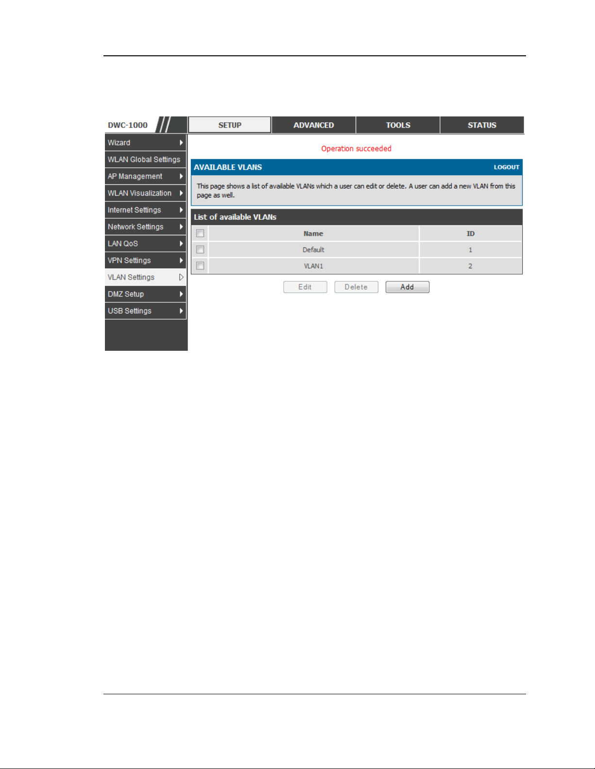
Setup > VLAN Settings > Available VLAN
The Available VLAN page shows a list of configured VLANs by name and VLAN ID.
A VLAN membership can be created by clicking the Add button below the List of
Available VLANs.
A VLAN membership entry consists of a VLAN identifier and the numerical VLAN
ID which is assigned to the VLAN membership. The VLAN ID value can be any
number from 2 to 4091. VLAN ID 1 is reserved for the default VLAN, which is used
for untagged frames received on the interface. By enabling Inter VLAN Routing, you
19
Page 21
Wireless Controller User Manual
will allow traffic from LAN hosts belonging to this VLAN ID to pass through to other
configured VLAN IDs that have Inter VLAN Routing enabled.
Figure 5: Adding VLAN memberships to the LAN
2.2.1 Associating VLANs to ports
In order to tag all traffic through a specific LAN port with a VLAN ID, you can
associate a VLAN to a physical port.
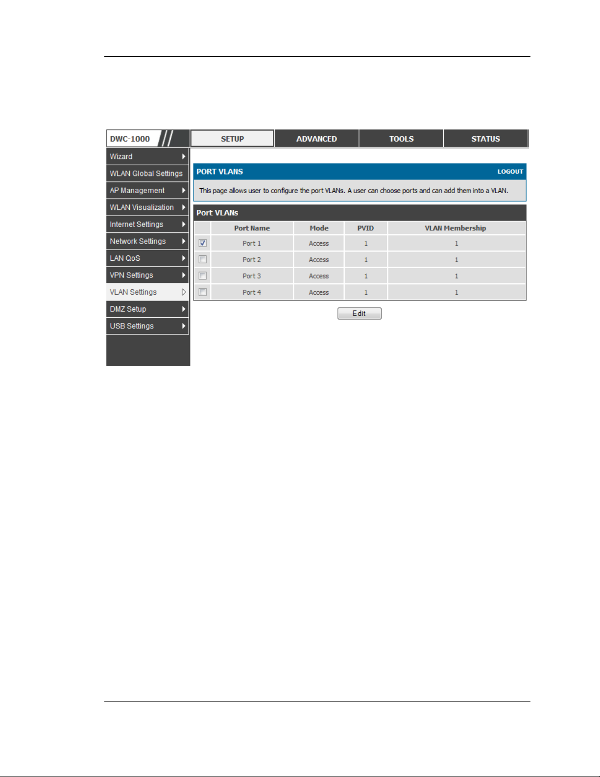
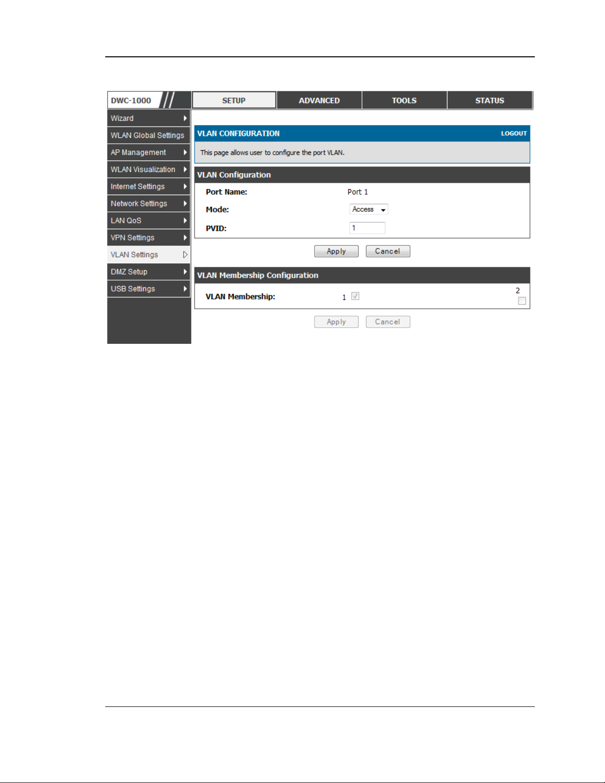
Setup > VLAN Settings > Port VLAN
VLAN membership properties for the LAN and wireless LAN are listed on this page.
The VLAN Port table displays the port identifier, the mode setting for that port and
VLAN membership information. The configuration page is accessed by selecting
one of the four physical ports or a configured access point and clicking Edit.
The edit page offers the following configuration options:
Mode: The mode of this VLAN can be General, Access, or Trunk. The
default is access.
In General mode the port is a member of a user selectable set of VLANs.
The port sends and receives data that is tagged or untagged with a VLAN
ID. If the data into the port is untagged, it is assigned the defined PVID. In
the configuration from Figure 4, Port 3 is a General port with PVID 3, so
untagged data into Port 3 will be assigned PVID 3. All tagged data sent out
of the port with the same PVID will be untagged. This is mode is typically
used with IP Phones that have dual Ethernet ports. Data coming from phone
20
Page 22
Wireless Controller User Manual
to the switch port on the controller will be tagged. Data passing through the
phone from a connected device will be untagged.
Figure 6: Port VLAN list
In Access mode the port is a member of a single VLAN (and only one). All
data going into and out of the port is untagged. Traffic through a port in
access mode looks like any other Ethernet frame.
In Trunk mode the port is a member of a user selectable set of VLANs. All
data going into and out of the port is tagged. Untagged coming into the port
is not forwarded, except for the default VLAN with PVID=1, which is
untagged. Trunk ports multiplex traffic for multiple VLANs over the same
physical link.
Select PVID for the port when the General mode is selected.
Configured VLAN memberships will be displayed on the VLAN
Membership Configuration for the port. By selecting one more VLAN
membership options for a General or Trunk port, traffic can be routed
between the selected VLAN membership IDs
21
Page 23
Wireless Controller User Manual
Figure 7: Configuring VLAN membership for a port
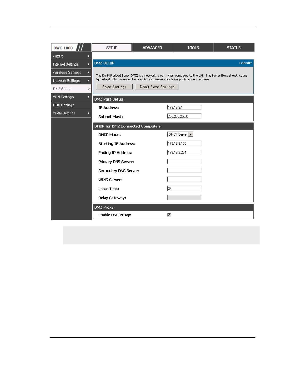
2.3 Configurable Port: DMZ Setup
This controller supports one of the physical ports to be configured as a secondary
WAN Ethernet port or a dedicated DMZ port. A DMZ is a subnetwork that is open to
the public but behind the firewall. The DMZ adds an additional layer of security to
the LAN, as specific services/ports that are exposed to the internet on the DMZ do not
have to be exposed on the LAN. It is recommended that hosts that must be exposed to
the internet (such as web or email servers) be placed in the DMZ network. Firewall
rules can be allowed to permit access specific services/ports to the DMZ from both
the LAN or WAN. In the event of an attack to any of the DMZ nodes, the LAN is not
necessarily vulnerable as well.
Setup > DMZ Setup > DMZ Setup Configuration
DMZ configuration is identical to the LAN configuration. There are no restrictions on
the IP address or subnet assigned to the DMZ port, other than the fact that it cannot
be identical to the IP address given to the LAN interface of this gateway.
22
Page 24
Wireless Controller User Manual
Figure 8: DMZ configuration
In order to configure a DMZ port, the controller configurable port must be set to
DMZ in the Setup > Internet Settings > Configurable Port page.
2.4 Universal Plug and Play (UPnP)
Advanced > Advanced Network > UPnP
Universal Plug and Play (UPnP) is a feature that allows the controller to discovery
devices on the network that can communicate with the controller and allow for auto
configuration. If a network device is detected by UPnP, the controller can open
internal or external ports for the traffic protocol required by that network device.
Once UPnP is enabled, you can configure the controller to detect UPnP-supporting
devices on the LAN (or a configured VLAN). If disabled, the controller will not allow
for automatic device configuration.
Configure the following settings to use UPnP:
23
Page 25
Wireless Controller User Manual
Advertisement Period: This is the frequency that the controller broadcasts UPnP
information over the network. A large value will minimize network traffic but
cause delays in identifying new UPnP devices to the network.
Advertisement Time to Live: This is expressed in hops for each UPnP packet. This
is the number of steps a packet is allowed to propagate before being discarded.
Small values will limit the UPnP broadcast range. A default of 4 is typical for
networks with few switches.
Figure 9: UPnP Configuration
UPnP Port map Table
The UPnP Port map Table has the details of UPnP devices that respond to the
controller advertisements. The following information is displayed for each detected
device:
Active: A yes/no indicating whether the port of the UPnP device that established a
connection is currently active
Protocol: The network protocol (i.e. HTTP, FTP, etc.) used by the DWC
Int. Port (Internal Port): The internal ports opened by UPnP (if any)
Ext. Port (External Port): The external ports opened by UPnP (if any)
IP Address: The IP address of the UPnP device detected by this controller
Click Refresh to refresh the portmap table and search for any new UPnP devices
24
Page 26
Wireless Controller User Manual
2.5 Captive Portal
LAN users can gain internet access via web portal authentication with the DWC.
Also referred to as Run-Time Authentication, a Captive Portal is ideal for a web
café scenario where users initiate HTTP connection requests for web access but are
not interested in accessing any LAN services. Firewall policies underneath will
define which users require authentication for HTTP access, and when a matching
user request is made the DWC will intercept the request and prompt for a username /
password. The login credentials are compared against the RunTimeAuth users in
user database prior to granting HTTP access.
Captive Portal is available for LAN users only and not for DMZ hosts.
Advanced > Captive Portal >Captive Portal Sessions
The Active Runtime internet sessions through the controller firewall are listed in the
below table. These users are present in the local or external user database and have
had their login credentials approved for internet acces s. A ‗Disconnect ‘ butto n
allows the DWC-1000 admin to selectively drop an authenticated user.
Figure 10: Active Runtime sessions
2.6 WLAN global configuration
Setup > WLAN Global Settings
Following are the options available to enable the WLAN function on DWC-1000
Enable WLAN Controller: Select this option to enable WLAN controller
functionality on the system. Clear the option to administratively disable the WLAN
controller. If you clear the option, all peer controller and APs that are associated
with this controller are disassociated.
25
Page 27
Wireless Controller User Manual
Disabling the WLAN controller does not affect non-WLAN features on the
controller, such as VLAN or STP functionality.
WLAN Controller Operational Status: Shows the operational status of the
controller
. The status can be one of the following values:
• Enabled
• Enable -Pending
• Disabled
• Disable-Pending
Figure 11: WLAN global configuration
IP Address: This field shows the IP address of the WLAN interface on the
controller. If the controller does not have the Routing Package installed, or if
routing is disabled, the IP address is the network interface. If the routing package is
26
Page 28

Wireless Controller User Manual
installed and enabled, this is the IP address of the routing or loopback interface you
configure for the controller features.
AP MAC Validation Method: Add the MAC address of the AP to the Valid AP
database, which can be kept locally on the controller or in an external RADIUS
server. When the controller discovers an AP that is not managed by another
ccontroller, it looks up the MAC address of the AP in the Valid AP database. If it
finds the MAC address in the database, the controller validates the AP and assumes
management. Select the database to use for AP validation and , optionally, for
authentication if the Require Authentication Passphrase option is selected.
• Local : If you selec t this op tion, you mus t add the MAC address o f e ach AP to the
local Valid AP database.
• RADIUS: If you select this option, you must configur e the MAC address of each
AP in an external RADIUS server.
Require Authentication Passphrase: Select this option to require APs to be
authenticated before they can associate with the controller. If you select this option,
you must configure the passphrase on the AP while it is in standalone mode as well
as in the Valid AP database.
RADIUS Authentication Server Name: Enter the name of the RADIUS server used
for AP and client authentications. The name can contain up to 32 alphanumeric
characters. Spaces, underscores, and dashes are also permitted. The controller acts
as the RADIUS client and performs all RADIUS transactions on behalf of the APs
and wireless clients.
RADIUS Authentication Server Configured: Indicates whether the RADIUS
authentication server is configured.
RADIUS Accounting Server Name: Enter the name of the RADIUS server used for
reporting wireless client associations and disassociations. The name can contain up
to 32 alphanumeric characters. Spaces, underscores, and dashes are also permitted.
RADIUS Accounting Server Configured: Indicates whether the RADIUS
accounting server is configured.
RADIUS Accounting: Select this option to enable RADIUS accounting for wireless
clients.
Country Code: Select the country code that represents the country where your
controller and APs operate. When you click Submit, a pop-up message asks you to
confirm the change. Wireless regulations vary from country to country. Make sure
you select the correct country code so that your WLAN system complies with the
regulations in your country.
27
Page 29

Wireless Controller User Manual
2.6.1 Wireless Discovery configuration
The wireless controller can discover, validate, authenticate, or monitor the
following system devices:
• Peer wir eless controllers
• APs
• Wirele ss c lients
• Rogue AP s
• Rogue wireless clients
Setup > AP Management > Poll List
The wireless controller can discover peer wireless controller and APs
regardless of whether these devices are connected to each other, located in the
same Layer 2 broadcast domain, or attached to different IP subnets. In order for
the controller to discover other WLAN devices and establish communication
with them, the devices must have their own IP address, must be able to find
other WLAN devices, and must be compatible. When the controller discovers
and validates APs, the controller takes over the management of the AP. If you
configure the AP in Standalone mode, the existing AP configuration is replaced
by the default AP Profile configuration on the controller.
L3/IP Discovery: Select or clear this option to enable or disable IP -based
discovery of access points and peer wireless controller. When the L3/IP
Discovery option is selected, IP polling is enabled and the controller will
periodically poll each address in the configured IP List. By default, L3/IP
Discovery is enabled.
List of IP address: Shows the list of IP addresses configured for discovery.
To remove entries from the list, select one or more entries and click Delete.
Hold t he " shift" key or ―co ntrol‖ key to selec t specific entry.
IP Address Range: This text field is used to add a range of IP address entries
to the IP List. Enter the IP address at the start of the address range in the From
field, and enter the IP address at the end of the range in the To field, then click
Add. All IP addresses in the range are added to the IP List. Only the last octet
is allowed to differ between the From address and the To address.
28
Page 30
Wireless Controller User Manual
Figure 12: Configuring the Wireless Discovery
L2/VLAN Discovery: The D-Link Wireless Device Discovery Protocol is a
good discovery method to use if the controller and APs are located in the same
Layer 2 multicast domain. The wireless controller periodically sends a
multicast packet containing the discovery message on each VLAN enabled for
discovery
This page includes the following buttons:
• Add— Adds the data in the IP Address or VLAN field to the appropriate list.
• Delete —Deletes the selected entry from the IP or VLAN list.
29
Page 31

Wireless Controller User Manual
Wireless Discovery status
Status > Global Info > IP Discovery
The IP Discovery list can contain the IP addresses of peer controller and APs for
the UWS to discover and associate with as part of the WLAN
IP Address: Shows the IP address of the device configured in the IP Discovery list
Status: The wireless discovery status is in one of the following states:
• Not Polled: The controller has not attempted to contact the IP address in the L3/IP
Discovery list.
• Polled: The controller has attempted to contact the IP address.
• Discovered: The controller contacted the peer controller or the AP in the L3/IP
Discovery list and has authenticated or validated the device.
• Discovered - Failed: The controller contacted the peer controller or the AP with
IP address in the L3/IP Discovery list and was unable to authenticate or validate the
device.
If the device is an access point, an entry appears in the AP failure list with a failure
reason.
Figure 13: Wireless Discovery status
This page includes the following buttons:
• Refres h—Updates the page with the latest information
30
Page 32

Wireless Controller User Manual
2.6.2 AP Profile Global Configuration
Advanced > AP Profile
Access Point Profile Summary page, you can Add, Copy, Edit, Delete AP
profiles. To add a new profile, click Add in AP Profile Summary page.
In the AP Profile Global Configuration page, enter the name of the profile in
the Profile Name field, select Hardware type and enter the valid VLAN ID
and then click Submit.
Figure 14: AP Profile Global Configuration
Profile Name: The Access Point profile name you added. Use 0 to 32
characters. Only alphanumeric characters are allowed. No special characters
are allowed.
Hardware Type: Select the hardware type for the APs that use this
profile. The hardware type is determined, in part, by the number of radios
the AP supports (single or dual) and the IEEE 802.11 modes that the radio
supports (a/b/g or a/b/g/n). The option available in the Hardware Type ID is:
• DW L-8600AP Dual Radio a/b/g/n
• DW L-3600AP Single Radio b/g/n
• DW L-6600AP Dual Radio a/b/g/n
31
Page 33

Wireless Controller User Manual
Wired Network Discovery VLAN ID: Enter the VLAN ID that the
controller uses to send tracer packets in order to detect APs connected to the
wired network.
AP Profile
Advanced > AP Profile
Access point configuration profiles are a useful feature for large wireless
networks with APs that serve a variety of different users. You can create
multiple AP profiles on the Controller to customize APs based on location,
function, or other criteria. Profiles are like templates, and once you create an AP
profile, you can apply that profile to any AP.
32
Page 34
Wireless Controller User Manual
Figure 15: AP Profile List
For each AP profile, you can configure the following features:
• Profile settings
(Name, Hardware Type ID, Wired Network Discovery VLAN ID)
• Radio settings
• SSID settings
Profile: The Access Point profile name you added. Use 0 to 32
characters.
Profile Status: can have one of the following values:
• Associated: The profile is configured, and one or more APs managed by the
controller are associated with this profile.
• Associated-Modified: The profile has been modified since it was applied to one
or more associated APs; the profile must be re-applied for the changes to take
effect.
• Apply Requested: After you select a profile and click Apply, the screen
refreshes and shows that an apply has been requested.
• Apply In Progress: The profile is being applied to all APs that use this profile.
33
Page 35

Wireless Controller User Manual
During this process the APs reset, and all wireless clients are disassociated from
the AP.
• Configured: The profile is configured, but no APs managed by the controller
currently use this profile.
Associate a profile with an AP. Entry of the AP is valid and available in
database of the controller.
This page includes the following buttons:
• Edit— To edit the existing AP profile.
• Delete — To delete the existing AP profile.
• Add— Allows to add a new AP profile
• Copy— Allows to copy the existing AP profile.
• Apply— Update the AP profile configuration details entered.
• Configure Radio — Allows to configure the AP profile Radio configuration.
• Configure SSID — Allows to configure the AP profile VAP configuration.
34
Page 36

Wireless Controller User Manual
Chapter 3. Connecting to the Internet:
WAN Setup
This contoller has two WAN ports that can be used to establish a connection to the
internet. The following ISP connection types are supported: DHCP, Static, PPPoE,
PPTP, L2TP (via USB modem).
It is assumed that you have arranged for internet service with your Internet Service
Provider (ISP). Please contact your ISP or network administrator for the configuration
information that will be required to setup the controller .
3.1 Internet Setup Wizard
Setup > Wizard > Internet
The Internet Connection Setup Wizard is available for users new to networking. By
going through a few straightforward configuration pages you can take the information
provided by your ISP to get your WAN connection up and enable internet access for
your network.
Figure 16: Internet Connection Setup Wizard
You can start using the Wizard by logging in with the administrator password for the
controller. Once authenticated set the time zone that you are located in, and then
choose the type of ISP connection type: DHCP, Static, PPPoE, PPTP, L2TP.
Depending on the connection type a username/password may be required to register
this controller with the ISP. In most cases the default settings can be used if the ISP
did not specify that parameter. The last step in the Wizard is to click the Connect
35
Page 37

Wireless Controller User Manual
button, which confirms the settings by establishing a link with the ISP. Once
connected, you can move on and configure other features in this controller.
3.2 WAN Configuration
Setup > Internet Settings > Option1 Setup
You must either allow the controller to detect WAN connection type automatically or
configure manually the following basic settings to enable Internet connectivity:
ISP Connection type: Based on the ISP you have selected for the primary WAN
link for this controller, choose Static IP address, DHCP client, Point-to-Point
Tunneling Protocol (PPTP), Point-to -Point Protocol over Ethernet (PPPoE), Layer
2 Tunneling Protocol (L2TP). Required fields for the selected ISP type become
highlighted. Enter the following information as needed and as provided by your
ISP:
PPPoE Profile Name. This menu lists configured PPPoE profiles, particularly
useful when configuring multiple PPPoE connections (i.e. for Japan ISPs that
have multiple PPPoE support).
ISP login information. This is required for PPTP and L2TP ISPs.
User Name
Password
Secret (required for L2TP only)
MPPE Encryption: For PPTP links, your ISP may require you to enable Microsoft
Point-to-Point Encryption (MPPE).
Split Tunnel (supported for PPTP and L2TP connection). This setting allows your
LAN hosts to access internet sites over this WAN link while still permitting VPN
traffic to be directed to a VPN configured on this WAN port.
If split tunnel is enab le d, DW C won‘t expect a default ro ute from the I SP server. In
such case, user has to take care of routing manually by configuring the routing from
Static Routing page.
Connectivity Type: To keep the connection always on, click Keep Connected. To
log out after the connection is idle for a period of time (useful if your ISP costs are
based on logon times), click Idle Timeout and enter the time, in minutes, to wait
before disconnecting in the Idle Time field.
My IP Address: Enter the IP address assigned to you by the ISP.
36
Page 38

Wireless Controller User Manual
Server IP Address: Enter the IP address of the PPTP or L2TP server.
3.2.1 WAN Port IP address
Your ISP assigns you an IP address that is either dynamic (newly generated each
time you log in) or static (permanent). The IP Address Source option allows you to
define whether the address is statically provided by the ISP or should be received
dynamically at each login. If static, enter your IP address, IPv4 subnet mask, and the
ISP gateway‘s IP address. P PTP and L2TP ISP s also can provide a static IP address
and subnet to configure, however the default is to receive that information
dynamically from the ISP.
3.2.2 WAN DNS Servers
The IP Addresses of WAN Domain Name Servers (DNS) are typically provided
dynamically from the ISP but in some cases you can define the static IP addresses of
the DNS servers. DNS servers map Internet domain names (example:
www.google.com) to IP addresses. Click to indicate whether to get DNS server
addresses automatically from your ISP or to use ISP-specified addresses. If its
latter, enter addresses for the primary and secondary DNS servers. To avoid
connectivity problems, ensure that you enter the addresses correctly.
3.2.3 DHCP WAN
For DHCP client connections, you can choose the MAC address of the controller to
register with the ISP. In so me ca se s you may need to clone the LAN host‘s MAC
address if the ISP is registered with that LAN host.
37
Page 39

Wireless Controller User Manual
Figure 17: Manual Option1 configuration
3.2.4 PPPoE
Setup > Internet Settings
The PPPoE ISP settings are defined on the WAN Configuration page. There are two
types of PPPoE ISP‘s supported by the DWC-1000: the standard username/password
PPPoE and Japan Multiple PPPoE.
38
Page 40

Wireless Controller User Manual
Figure 18: PPPoE configuration for standard ISPs
Most PPPoE ISP‘s use a single control and data connection, and require username /
password credentials to login and authenticate the DWC-1000 with the ISP. The ISP
connection type for this case is ―PPPoE (Username/Password) ‖. T he GUI wi ll
prompt you for authentication, service, and connection settings in order to establish
the PPPoE link.
For so me ISP‘s, most popular in Japan, the use of ―Japanese Multiple PPPoE‖ is
required in order to establish concurrent primary and secondary PPPoE connections
between the DWC-1000 and the ISP. The Primary connection is used for the bulk of
data and internet traffic and the Secondary PPPoE connection carries ISP specific
(i.e. control) traffic between the DWC-1000 and the ISP.
39
Page 41

Wireless Controller User Manual
Figure 19: Option1 configuration for Japanese Multiple PPPoE (part 1)
There are a few key elements of a multiple PPPoE connection:
Primary and secondary connections are concurrent
Each session has a DNS server source for domain name lookup, this can be assigned by
the ISP or configured through the GUI
The DWC-1000 acts as a DNS proxy for LAN users
Only HTTP requests that specifically identify the secondar y con nection‘s domain name
(for example *.flets) will use the secondary profile to access the content available
through this secondary PPPoE terminal. All other HTTP / HTTPS requests go through
the primary PPPoE connection.
40
Page 42

Wireless Controller User Manual
When Japanese multiple PPPoE is configured and secondary connection is up, some predefined
routes are added on that interface. These routes are needed to access the internal domain of the
ISP where he hosts various services. These routes can even be configured through the static
routing page as well.
Figure 20: Option1 configuration for Multiple PPPoE (part 2)
3.2.5 Russia L2TP and PPTP WAN
For Russia L2TP WAN connections, you can choose the address mode of the
connection to get an IP address from the ISP or configure a static IP address
provided by the ISP. For DHCP client connections, you can choose the MAC
address of the controller to register with the ISP. In some cases you may need to
clone the LAN host‘s MAC ad dress if the ISP is registered with that LAN ho st.
41
Page 43

Wireless Controller User Manual
Figure 21: Russia L2TP ISP configuration
3.2.6 WAN Configuration in an IPv6 Network
Advanced > IPv6 > IPv6 Option1 Config
For IPv6 WAN connections, this controller can have a static IPv6 address or receive
connection information when configured as a DHCPv6 client. In the case where the
ISP assigns you a fixed address to access the internet, the static configuration
settings must be completed. In addition to the IPv6 address assigned to your
controller, the IPv6 prefix length defined by the ISP is needed. The default IPv6
Gateway address is the server at the ISP that this controller will connect to for
accessing the internet. Th e primary and seco nd ary DNS servers on t he ISP ‘s IPv6
network are used for resolving internet addresses, and these are provided along with
the static IP address and prefix length from the ISP.
42
Page 44

Wireless Controller User Manual
When the ISP allows you to obtain the WAN IP settings via DHCP, you need to
provide details for the DHCPv6 client configuration. The DHCPv6 client on the
gateway can be either stateless or stateful. If a stateful client is selected the gateway
will con nect to the ISP ‘s DHCP v6 server for a leased address. For stateless DHCP
there need not be a DHCPv6 server available at the ISP, rather ICMPv6 discover
messages will originate from this gateway and will be used for auto configuration. A
third option to specify the IP address and prefix length of a preferred DHCPv6
server is available as well.
Figure 22: IPv6 WAN Setup page
Prefix Delegation: Select this option to request controller advertisement prefix from
any available DHCPv6 servers available on the ISP, the obtained prefix is updated
to the advertised prefixes on the LAN side. This option can be selected only in
Statesless Address Auto Configuration mode of DHCPv6 Client.
43
Page 45

Wireless Controller User Manual
When IPv6 is PPPoE type, the following PPPoE fields are enabled.
Username: Enter the username required to log in to the ISP.
Password: Enter the password required to login to the ISP.
Authentication Type: The type of Authentication in use by the profile: Auto-
Negotiate/PAP/CHAP/MS-CHAP/MS-CHAPv2.
Dhcpv6 Options: The mode of Dhcpv6 client that will start in this mode:
disable dhcpv6/stateless dhcpv6/stateful dhcpv6/stateless dhcpv6 with prefix
delegation.
Primary DNS Server: Enter a valid primary DNS Server IP Address.
Secondary DNS Server: Enter a valid secondary DNS Server IP Address.
Click Save Settings to save your changes.
3.2.7 Checking WAN Status
Setup > Internet Settings > WAN1 Status
The status and summary of configured settings for both WAN1 and WAN2 are
available on the WAN Status page. You can view the following key connection
status information for each WAN port:
Connection time: The connection uptime
Connection type: Dynamic IP or Static IP
Connection state: This is whether the WAN is connected or disconnected to
an ISP. The Link State is whether the physical WAN connection in place;
the Link State can be UP (i.e. cable inserted) while the WAN Connection
State is down.
IP address / subnet mask: IP Address assigned
Gateway IP address: WAN Gateway Address
44
Page 46

Wireless Controller User Manual
Figure 23: Connection Status information of Option1
The WAN status page allows you to Enable or Disable static WAN links. For WAN
settings that are dynamically received from the ISP, you can Renew or Release the
link parameters if required.
3.3 Features with Multiple WAN Links
This controller supports multiple WAN links. This allows you to take advantage of
failover and load balancing features to ensure certain internet dependent services are
prioritized in the event of unstable WAN connectivity on one of the ports.
45
Page 47

Wireless Controller User Manual
Setup > Internet Settings > Option Mode
To use Auto Failover or Load Balancing, WAN link failure detection must be
configured. This involves accessing DNS servers on the internet or ping to an internet
address (user defined). If required, you can configure the number of retry attempts
when the link seems to be disconnected or the threshold of failures that determines if
a WAN port is down.
3.3.1 Auto Failover
In this case one of your WAN ports is assigned as the primary internet link for all
internet traffic. The secondary WAN port is used for redundancy in case the primary
link goes down for any reason. Both WAN ports (primary and secondary) must be
configured to co nnect to the respective ISP‘s before enabling this feature. The
secondary WAN port will remain unconnected until a failure is detected on the
primary link (either port can be assigned as the primary). In the event of a failure on
the primary port, all internet traffic will be rolled over to the backup port. When
configured in Auto Failover mode, the link status of the primary WAN port is
checked at regular intervals as defined by the failure detection settings.
Note that both WAN1 and WAN2 can be configured as the primary internet link.
Auto-Rollover using WAN port
Primary WAN: Selected WAN is the primary link (WAN1/WAN2)
Secondary WAN: Selected WAN is the secondary link.
Failover Detection Settings: To check connectivity of the primary internet link, one
of the following failure detection methods can be selected:
DNS lookup using WAN DNS Servers: DNS Lookup of the DNS Servers of
the primary link are used to detect primary WAN connectivity.
DNS lookup using DNS Servers: DNS Lookup of the custom DNS Servers
can be specified to check the connectivity of the primary link.
Ping these IP addresses: These IP's will be pinged at regular intervals to
check the connectivity of the primary link.
Retry Interval is: The number tells the controller how often it should run the
above configured failure detection method.
Failover after: This sets the number of retries after which failover is
initiated.
3.3.2 Load Balancing
This feature allows you to use multiple WAN links (and presu mabl y multiple ISP‘s)
simultaneously. After configuring more than one WAN port, the load balancing
option is available to carry traffic over more than one link. Protocol bindings are
used to segregate and assign services over one WAN port in order to manage
internet flow. The configured failure detection method is used at regular intervals on
all configured WAN ports when in Load Balancing mode.
DWC-1000 currently support three algorithms for Load Balancing:
Round Robin: This algorithm is particularly useful when the connection speed of
one WAN port greatly differs from another. In this case you can define protocol
bindings to route low-latency services (such as VOIP) over the higher-speed link
46
Page 48

Wireless Controller User Manual
and let low-volume background traffic (such as SMTP) go over the lower speed link.
Protocol binding is explained in next section.
Spill Over: If Spill Over method is selected, WAN1 acts as a dedicated link till a
threshold is reached. After this, WAN2 will be used for new connections. You can
configure spill-over mode by using folloing options:
Load Tolerance: It is the percentage of bandwidth after which the controller
switches to secondary WAN.
Max Bandwidth: This sets the maximum bandwidth tolerable by the primary
WAN.
If the link bandwidth goes above the load tolerance value of max bandwidth, the
controller will spill-over the next connections to secondary WAN.
For example, if the maximum bandwidth of primary WAN is 1 Kbps and the load
tolerance is set to 70. Now every time a new connection is established the
bandwidth increases. After a certain number of connections say bandwidth reached
70% of 1Kbps, the new connections will be spilled-over to secondary WAN. The
maximum value of load tolerance is 80 and the least is 20.
Protocol Bindings: Refer Section 3.4.3 for details
Load balancing is particularly useful when the connection speed of one WAN port
greatly differs from another. In this case you can define protocol bindings to route
low-latency services (such as VOIP) over the higher-speed link and let low-volume
background traffic (such as SMTP) go over the lower speed link.
47
Page 49

Wireless Controller User Manual
Figure 24: Load Balancing is available when multiple WAN ports are
configured and Protocol Bindings have been defined
3.3.3 Protocol Bindings
Advanced > Routing > Protocol Bindings
Protocol bindings are required when the Load Balancing feature is in use. Choosing
from a list of configured services or any of the user-defined services, the type of
traffic can be assigned to go over only one of the available WAN ports. For
increased flexibility the source network or machines can be specified as well as the
destination network or machines. For example the VOIP traffic for a set of LAN IP
addresses can be assigned to one WAN and any VOIP traffic from the remaining IP
addresses can be assigned to the other WAN link. Protocol bindings are only
48
Page 50

Wireless Controller User Manual
applicable when load balancing mode is enabled and more than one WAN is
configured.
Figure 25: Protocol binding setup to associate a service and/or LAN
source to a WAN and/or destination network
3.4 Routing Configuration
Routing between the LAN and WAN will impact the way this controller handles
traffic that is received on any of its physical interfaces. The routing mode of the
gateway is core to the behaviour of the traffic flow between the secure LAN and the
internet.
3.4.1 Routing Mode
Setup > Internet Settings > Routing Mode
This device supports classical routing, network address translation (NAT), and
transport mode routing.
With classical routing, devices on the LAN can be directly accessed from the
internet by their public IP addresses (assuming appropriate firewall settings). If
your ISP has assigned an IP address for each of the computers that you use,
select Classic Routing.
49
Page 51

Wireless Controller User Manual
NAT is a technique which allows several computers on a LAN to share an
Internet connection. The computers on the LAN use a "private" IP address
range while the WAN port on the controller is configured with a single "public"
IP address. Along with connection sharing, NAT also hides internal IP
addresses from the computers on the Internet. NAT is required if your ISP has
assigned only one IP address to you. The computers that connect through the
controller will need to be assigned IP addresses from a private subnet.
Transparent routing between the LAN and WAN does not perform NAT.
Broadcast and multicast packets that arrive on the LAN interface are switched
to the WAN and vice versa, if they do not get filtered by firewall or VPN
policies. To maintain the LAN and WAN in the same broadcast domain select
Transparent mode, which allows bridging of traffic from LAN to WAN and vice
versa, except for controller -terminated traffic and other management traffic.
All DWC features are supported in transparent mode assuming the LAN and
WAN are configured to be in the same broadcast domain.
NAT routing has a feature called ―NAT Hair -pinni ng ‖ that allows internal net work
users on the LAN and DMZ to access internal servers (eg. an internal FTP server)
using their externally-known do main name. This is also referred to as ― NAT
loopba ck‖ since LAN generated traffic is red ir ected through the firewall to reach
LAN servers by their external name.
50
Page 52

Wireless Controller User Manual
Figure 26: Routing Mode is used to configure traffic routing between
WAN and LAN, as well as Dynamic routing (RIP)
51
Page 53

Wireless Controller User Manual
3.4.2 Dynamic Routing (RIP)
Setup > Internet Settings > Routing Mode
Dynamic routing using the Routing Information Protocol (RIP) is an Interior
Gateway Protocol (IGP) that is common in LANs. With RIP this controller can
exchange routing information with other supported controllers in the LAN and allow
for dynamic adjustment of routing tables in order to adapt to modifications in the
LAN without interrupting traffic flow.
The RIP direction will define how this controller sends and receives RIP packets.
Choose between:
Both: The controller both broadcasts its routing table and also processes RIP
information received from other controllers. This is the recommended
setting in order to fully utilize RIP capabilities.
Out Only: The controller broadcasts its routing table periodically but does
not accept RIP information from other controllers.
In Only: The controller accepts RIP information from other controller, but
does not broadcast its routing table.
None: The controller neither broadcasts its route table nor does it accept any
RIP packets from other controllers. This effectively disables RIP.
The RIP version is dependent on the RIP support of other routing
devices in the LAN.
Disabled: This is the setting when RIP is disabled.
RIP-1 is a class-based routing version that does not include subnet
information. This is the most commonly supported version.
RIP-2 includes all the functionality of RIPv1 plus it supports subnet
information. Though the data is sent in RIP-2 format for both RIP-2B and
RIP-2M, the mode in which packets are sent is different. RIP-2B broadcasts
data in the entire subnet while RIP-2M sends data to multicast addresses.
If RIP-2B or RIP-2M is the selected version, authentication between this controller
and other controllers (configured with the same RIP version) is required. MD5
authentication is used in a first/second key exchange process. The authentication
key validity lifetimes are configurable to ensure that the routing information
exchange is with current and supported controllers detected on the LAN.
52
Page 54

Wireless Controller User Manual
3.4.3 Static Routing
Advanced > Routing > Static Routing
Advanced > IPv6 > IPv6 Static Routing
Manually adding static routes to this device allows you to define the path selection
of traffic from one interface to another. There is no communication between this
controller and other devices to account for changes in the path; once configured the
static route will be active and effective until the network changes.
The List of Static Routes displays all routes that have been added manually by an
administrator and allows several operations on the static routes. The List of IPv4
Static Routes and List of IPv6 Static Routes share the same fields (with one
exception):
Name: Name of the route, for identification and management.
Active: Determines whether the route is active or inactive. A route can be
added to the table and made inactive, if not needed. This allows routes to be
used as needed without deleting and re-adding the entry. An inactive route is
not broadcast if RIP is enabled.
Private: Determines whether the route can be shared with other controllers
when RIP is enabled. If the route is made private, then the route will not be
shared in a RIP broadcast or multicast. This is only applicable for IPv4
static routes.
Destination: the route will lead to this destination host or IP address.
IP Subnet Mask: This is valid for IPv4 networks only, and identifies the
subnet that is affected by this static route
Interface: The physical network interface (WAN1, WAN2, DMZ or LAN),
through which this route is accessible.
Gateway: IP address of the gateway through which the destination host or
network can be reached.
Metric: Determines the priority of the route. If multiple routes to the same
destination exist, the route with the lowest metric is chosen.
53
Page 55

Wireless Controller User Manual
Figure 27: Static route configuration fields
3.5 WAN Port Settings
Advanced > Advanced Network > Option Port Setup
The physical port settings for each WAN link can be defined here. If your ISP account
defines the WAN port speed or is associated with a MAC address, this information is
required by the controller to ensure a smooth connection with the network.
The default MTU size supported by all ports is 1500. This is the largest packet size
that can pass through the interface without fragmentation. This size can be increased,
however large packets can introduce network lag and bring down the interface speed.
Note that a 1500 byte size packet is the largest allowed by the Eth ernet protocol at the
network layer.
The port speed can be sensed by the controller when Auto is selected. With this
option the optimal port settings are determined by the controller and network. The
duplex (half or full) can be defined based on the port support, as well as one of three
port speeds: 10 Mbps, 100 Mbps and 1000 Mbps (i.e. 1 Gbps). The default setting is
100 Mbps for all ports.
The default MAC address is defined during the manufacturing process for the
interfaces, and can uniquely identify this controller. You can customize each WAN
port‘s MAC addres s as need ed, either by letting the WAN por t assume the curr ent
LAN host ‘s MAC address or by entering a MAC address manua ll y.
54
Page 56

Wireless Controller User Manual
Figure 28: Physical WAN port settings
55
Page 57

Wireless Controller User Manual
Chapter 4. Monitoring Status and
Statistics
4.1 System Overview
The Status page allows you to get a detailed overview of the system configuration.
The settings for the wired and wireless interfaces are displayed in the DWC-1000
Status page, and then the resulting hardware resource and controller usage details are
summarized on the controller Dashboard.
4.1.1 Device Status
Status > Device Info > Device Status
The DWC-1000 Status page gives a summary of the controller configuration settings
configured in the Setup and Advanced menus. The static hardware serial number and
current firmware version are presented in the General section. The WAN and LAN
interface information shown on this page are based on the administrator
configuration parameters. The radio band and channel settings are presented below
along with all configured and active APs that are enabled on this controller.
56
Page 58

Wireless Controller User Manual
Figure 29: Device Status display
57
Page 59

Wireless Controller User Manual
Figure 30: Device Status display (continued)
4.1.2 Resource Utilization
Status > Device Info > Dashboard
The Dashboard page presents hardware and usage statistics. The CPU and Memory
utilization is a function of the available hardware and current configuration and
traffic through the controller. Interface statistics for the wired connections (LAN,
WAN1, WAN2/DMZ, VLANs) provide indication of packets through and packets
dropped by the interface. Click refresh to have this page retrieve the most current
statistics.
58
Page 60

Wireless Controller User Manual
Figure 31: Resource Utilization statistics
Figure 32: Resource Utilization data (continued)
59
Page 61

Wireless Controller User Manual
4.2 Traffic Statistics
4.2.1 Wired Port Statistics
Status > Traffic Monitor > Device Statistics
Detailed transmit and receive statistics for each physical port are presented here.
Each interface (WAN1, WAN2/DMZ, LAN, and VLANs) have port specific packet
level information provided for review. Transmitted/received packets, port collisions,
and the cumulating bytes/sec for transmit/receive directions are provided for each
interface along with the port up time. If you suspect issues with any of the wired
ports, this table will help diagnose uptime or transmit level issues with the port.
60
Page 62

Wireless Controller User Manual
The statistics table has auto-refresh control which allows display of the most current
port level data at each page refresh. The default auto-refresh for this page is 10
seconds.
Figure 33: Physical port statistics
4.3 Active Connections
4.3.1 Sessions through the controller
Status > Active Sessions
This table lists the active internet sessions through the controllers firewall. The
session‘s pr otocol, state, lo cal and remote IP addresses are shown.
61
Page 63

Wireless Controller User Manual
Figure 34: List of current Active Firewall Sessions
62
Page 64

Wireless Controller User Manual
Field
Description
Policy Name
IKE or VPN policy associated with this SA.
Endpoint
IP address of the remote VPN gateway or client.
Tx (KB)
Kilobytes of data transmitted over this SA.
Tx (Packets)
Number of IP packets transmitted over this SA.
State
Status of the SA for IKE policies: Not Connected or IPsec SA Established.
4.3.2 LAN Clients
Status > LAN Client Info >LAN Clients
The LAN clients to the controller are identified by an ARP scan through the LAN
switch. The NetBios name (if available), IP address and MAC address of discovered
LAN hosts are displayed.
Figure 35: List of LAN hosts
4.3.3 Active VPN Tunnels
Status > Active VPNs
You can view and change the status (connect or drop) of the controllers IPsec
security associations. Here, the active IPsec SAs (security associations) are listed
along with the traffic details and tunnel state. The traffic is a cumulative measure of
transmitted/received packets since the tunnel was established.
If a VPN policy state is ―IPsec SA Not Establi sh ed‖, it can be enabled by clicking
the Connect button of the corresponding policy. The Active IPsec SAs table displays
a list of active IPsec SAs. Table fields are as follows.
63
Page 65

Wireless Controller User Manual
Field
Description
User Name
The SSL VPN user that has an active tunnel or port forwarding session to this
controller.
IP Address
IP address of the remote VPN client.
Local PPP Interface
The interface (WAN1 or WAN2) through which the session is active.
Peer PPP Interface IP
The assigned IP address of the virtual network adapter.
Connect Status
Status of the SSL connection between this controller and the remote VPN client:
Not Connected or Connected.
Figure 36: List of current Active VPN Sessions
All active SSL VPN connections, both for VPN tunnel and VPN Port forwarding, are
displayed on this page as well. Table fields are as follows.
4.4 Access Point status
Status > Access Point Info> APs Summary
The List of AP page shows summary information about managed, failed, and
rogue access points the controller has discovered or detected. The status entries can
be deleted manually. To clear all APs from the All Access Points status page except
Managed Access Points, click Delete All.
64
Page 66

Wireless Controller User Manual
To configure an Authentication Failed AP to be managed by the controller the next
time it is discovered, select the check box next to the MAC address of the AP
and\click Manage. You will be presented with the Valid Access Point Configuration
page.
Figure 37: AP status
MAC Address: Shows the MAC address of the access point.
IP Address: The network address of the access point.
Age: Shows how much time has passed since the AP was last detected and the
information was last updated.
Status Shows the access point status:.
• M anaged—The AP profile configuration has been applied to the AP and it's
operating in managed mode.
• No Da tabase Entry— MAC address of the AP does not appear in the local or
RADIUS Valid AP database.
• Authenticatio n (Failed AP) —The AP failed to be authenticated by the controller
or RADIUS server. Since AP is not configured as a valid AP which the correct
local or RADIUS authentication information.
• Failed— The controller lost contact with the AP; a failed entry will remain in the
managed AP database unless you remove it. Note that a managed AP will
temporarily show a failed status during a reset.
65
Page 67

Wireless Controller User Manual
• Rogue —The AP has not attempted to contact the controller and the MAC address
of the AP is not in the Valid AP database.
Radio: Shows the wireless radio mode the AP is using.
Channel: Shows the operating channel for the radio.
This page includes the following buttons:
• Delete All — Manually clear all APs from the All Access Points status page
except Managed Access Points.
• Manage — Configure an Authentication Failed AP to be managed by the
controller the next time it is discovered. Select the check box next to the MAC
address of the AP before you click Manage You will be presented with the Valid
Access Point Configuration page. You can then configure the AP and click Submit
to save the AP in the local Valid AP database. If you use a RADIUS server for AP
validation, you must add the MAC address of the AP to the AP database on the
RADIUS server.
• Ac knowledge — Identify an AP as an Acknowledged Rogue. Select the check box
next to the MAC address of the AP before you click Acknowledge. The controller
adds the AP to the Valid AP database as an Acknowledged Rogue.
• View Details — To view the details configured APs. Select the check box next to
the MAC address of the AP before you click View Details.
• Refres h—Updates the page with the latest information
Managed AP Status
Status > Access Point Info> Managed AP Status
In the Managed AP Status page, you can access a variety of information about
each AP that the controller manages.
66
Page 68

Wireless Controller User Manual
Figure 38: Managed AP status
MAC Address: The Ethernet address of the controller-managed AP.
IP Address: The network IP address of the managed AP.
Age: Time since last communication between the Controller and the AP.
Status The current managed state of the AP. The possible values are:
• Discovered: The AP is discovered and by the controller, but is not yet
authenticated.
• Authenticated: The AP has been validated and authenticated (if authentication
is enabled), but it is not configured.
• Managed: The AP profile configuration has been applied to the AP and it's
operating in managed mode.
Failed: The Controller lost contact with the AP, a failed entry will remain in the
managed AP database unless you remove it. Note that a managed AP will
temporarily show a failed status during a reset.
Profile: The AP profile configuration currently applied to the managed AP. The
profile is assigned to the AP in the valid AP database.
Radio Interface: Shows the wireless radio mode that each radio on the AP is
using.
This page includes the following buttons:
• Delete —Manually clear existing APs
67
Page 69

Wireless Controller User Manual
• View AP details — Shows detailed status information collected from the AP.
• View Rad io details — Shows detailed status for a radio interface
• V iew Neighbor d etails — Shows the neighbour APs that the specified AP has
discovered through periodic RF scans on the selected radio interface
• View Neighbor Clients — Shows information about wireless clients associated
with an AP or detected by the AP radio
• View V AP details — Shows summary information about the virtual access
points (VAPs) for the selected AP and radio interface on the APs that the
controller manages
AP RF Scan Status
Status > Access Point Info> AP RF Scan Status
The radios on each AP can periodically scan the radio frequency to collect
information about other APs and wireless clients that are within range. In
normal operating mode the AP always scans on the operational channel for
the radio.
MAC Address: The Ethernet MAC address of the detected AP. This could be a
physical radio interface or VAP MAC.
SSID: Service Set ID of the network, which is broadcast in the detected beacon
frame.
Physical Mode: Indicates the 802.11 mode being used on the AP.
Channel: Transmit channel of the AP.
Status: Indicates the managed status of the AP, whether this is a valid AP known to
the controller or a Rogue on the network. The valid values are:
• Mana ged: The neighbor AP is managed by the wireless s ys te m.
• Standalone: The AP i s managed in standalone mode and co nfigured as a valid AP
entry (local or RADIUS).
• Rogue: T he AP is classified as a threat by one of the threat detection algorithms.
• Unknown: The AP is detected in the net work but is not class ified as a threat by
the threat detection algorithms.
Age: Time since this AP was last detected in an RF scan. Status entries for the RF
Scan Status page are collected at a point in time and eventually age out. The age
value for each entry shows how long ago the controller recorded the entry.
68
Page 70

Wireless Controller User Manual
Figure 39: AP RF Scan Status
4.5 Global Status
Peer Controller Status
Status > Global Info > Peer Controller > Status
The Peer Controller Status page provides information about other Wireless
Controllers in the network. Peer wireless controllers within the same cluster
exchange data about themselves, their managed APs, and clients. The controller
maintains a database with this data so you can view information about a peer, such
as its IP address and software version. If the controller loses contact with a peer, all
of the data for that peer is deleted. One controller in a cluster is elected as a Cluster
Controller. The Cluster Controller collects status and statistics from all the other
controllers in the cluster, including information about the APs peer controllers
manage and the clients associated to those APs.
Cluster Controller IP Address: IP address of the controller that controls the
cluster.
Peer Controllers: Displays the number of peer controller in the cluster.
List of Peer Controllers:
IP Address: IP address of the peer wireless controller in the cluster.
Vendor ID: Vendor ID of the peer controller software.
69
Page 71

Wireless Controller User Manual
Software Version: The software version for the given peer controller.
Protocol Version: Indicates the protocol version supported by the software on the
peer controller.
Discovery Reason: The discovery method of the given peer controller, which can
be through an L2 Poll or IP Poll
Managed AP Count: Shows the number of APs that the controller currently
manages.
Age: Time since last communication with the controller in Hours, Minutes, and
Seconds.
Figure 40: Peer Controller Status
This page includes the following buttons:
• Refres h—Updates the page with the latest information
Peer Controller Configuration Status
Status > Global Info > Peer Controller > Configuration
You can push portions of the controller configuration from one controller to
another controller in the cluster. The Peer Controller Configuration Status page
displays information about the configuration sent by a peer controller in the cluster.
It also identifies the IP address of each peer controller that received the
configuration information
70
Page 72

Wireless Controller User Manual
Peer IP Address: Shows the IP address of each peer wireless controller in the
cluster that received configuration information.
Configuration Controller IP Address: Shows the IP Address of the controller that
sent the configuration information.
Configuration: Identifies which parts of the configuration the controller received
from the peer controller.
Timestamp: Shows when the configuration was applied to the controller. The time
is displayed as UTC time and therefore only useful if the administrator has
configured each peer controller to use NTP.
Figure 41: Peer Controller Configuration Status
This page includes the following buttons:
• Refres h—Updates the page with the latest information
Peer Controller Managed AP Status
Status > Global Info > Peer Controller > Managed AP
The Peer Controller Managed AP Status page displays information about the APs
that each peer controller in the cluster manages. Use the menu above the table to
select the peer controller with the AP information to display. Each peer controller
is identified by its IP address
MAC Address: Shows the MAC address of each AP managed by the peer
controller.
71
Page 73

Wireless Controller User Manual
Peer Controller IP: Shows the IP address of the peer controller that manages the
AP. This fie ld displays when ―All‖ is selected from the drop -down menu.
Location: The descriptive location configured for the managed AP.
AP IP Address: The IP address of the AP.
Profile: The AP profile applied to the AP by the controller.
Hardware ID: The Hardware ID associated with the AP hardware platform
Figure 42: Peer Controller Managed AP Status
Configuration Receive Status
Global Info > Config Receive Status
The Peer Controller Configuration feature allows you to send the critical wireless
configuration from one controller to all other controllers. In addition to keeping the
controllers synchronized, this function enables the administrator to manage all
wireless controllers in the cluster from one controller. The Peer Controller
Configuration Received Status page provides information about the configuration a
controller has received from one of its peers
Current Receive Status: Indicates the global status when wireless configuration is
received from a peer controller. The possible status values are as follows:
• Not Star ted
• Receiving Configuration
72
Page 74

Wireless Controller User Manual
• Saving Configuration,
• Appl yi ng AP Profile Confi guration
• Success
• Failure - Invalid Code Version
• Failure - Invalid Hardware Version
• Failure - Invalid Configuration
Last Configuration Received: Peer controller IP Address indicates the last
controller from which this controller received any wireless configuration data.
Configuration: Indicates which portions of configuration were last received from a
peer controller, which can be one or more of the following:
• Global
• Discov ery
• Chan nel/Power
• AP Database
• AP Pro file s
• Known Client
• Captive Portal
• RADIUS Client
• QoS AC L
• QoS Di ffServ
If the controller has not received any configuration for another controller, the value
is None.
Timestamp: Indicates the last time this controller received any configuration data
from a peer controller. The Peer Controller Managed AP Status page displays
information about the APs that each peer controller in the cluster manages. Use the
menu above the table to select the peer controller with the AP information to
display. Each peer controller is identified by its IP address
73
Page 75

Wireless Controller User Manual
Figure 43: Configuration Receive Status
74
Page 76

Wireless Controller User Manual
4.6 Wireless Client Status
Assocaited Client Status
Status > Wireless Client Info> Associated Clients > Status
You can view a variety of information about the wireless clients that are associated
with the APs the controller manages.
MAC Address: The Ethernet address of the client station. If the MAC address is
followed by an asterisk (*), the client is associated with an AP managed by a peer
controller.
AP MAC Address: The Ethernet address of the AP.
SSID: The network on which the client is connected.
BSSID: The Ethernet MAC address for the managed AP VAP where this client is
associated.
Status: Shows status information about wireless clients that are associated with
APs managed by the controller
Figure 44: Associated Client Status
This page includes the following buttons:
• Disassoc ia te —Disassociates the selected client from the managed AP.
• View Details — Display associated client details.
• View AP Details — Display associated AP details.
75
Page 77

Wireless Controller User Manual
• View SSID Details— Lists the SSIDs of the networks that each wireless
client associated with a managed AP has used for WLAN access
• View VAP Details — Shows information about the VAPs on the managed AP
that have associated wireless clients
• View Neigh our AP Status — Shows information about access points that the
client detects.
Associated Client SSID Status
Status > Wireless Client Info> Associated Clients > SSID Status
Each managed AP can have up to 16 different networks that each has a unique
SSID. Although several wireless clients might be connected to the same physical
AP, they might not connect by using the same SSID
SSID: Indicates the network on which the client is connected.
Client MAC Address: The Ethernet address of the client station.
Figure 45: Associated Client SSID Status
This page includes the following buttons:
• Disassoc ia te—Disassociates the client from the managed AP.
• View Client Details — Display associated client details.
• Refres h—Updates the page with the latest information
76
Page 78

Wireless Controller User Manual
Assocaited Client VAP Status
Status > Wireless Client Info> Associated Clients > VAP Status
Each AP has 16 Virtual Access Points (VAPs) per radio, and every VAP has a
unique MAC address (BSSID).The VAP Associated Client Status page which shows
information about the VAPs on the managed AP that have associated wireless
clients. To disconnect a client from an AP, select the box next to the BSSID, and
then click Disassociate
BSSID: Indicates the Ethernet MAC address for the managed AP VAP where this
client is associated.
SSID: Indicates the SSID for the managed AP VAP where this client is associated.
AP MAC Address: This field indicates the base AP Ethernet MAC address for the
managed AP.
Radio: Displays the managed AP radio interface the client is associated to and its
configured mode.
Client MAC Address: The Ethernet address of the client station.
Client IP Address: The IP address of the client station.
Figure 46: Associated Client VAP Status
This page includes the following buttons:
• Disassoc ia te—Disassociates the client from the managed AP.
• Refres h—Updates the page with the latest information.
77
Page 79

Wireless Controller User Manual
Controller Assocaited Client Status
Status > Wireless Client Info> Associated Clients > Controller Status
This shows information about the controller that manages the AP to which the
client is associated
Controller IP Address: Shows the IP address of the controller that manages the AP
to which the client is associated.
Client MAC Address: Shows the MAC address of the associated client.
Figure 47: Controller Associated Client Status
This page includes the following buttons:
• Disassoc ia te—Disassociates the client from the managed AP.
• View Client Details — Display associated client details.
• Refres h—Updates the page with the latest information
Detected Client Status
Status > Wireless Client Info> Detected Clients
Wireless clients are detected by the wireless system when the clients either attempt
to interact with the system or when the system detects traffic from the clients. The
Detected Client Status page contains information about clients that have
authenticated with an AP as well information about clients that disassociate and are
no longer connected to the system.
MAC Address: The Ethernet address of the client.
78
Page 80

Wireless Controller User Manual
Client Name: Shows the name of the client, if available, from the Known Client
Database. If client is not in the database then the field is blank.
Client Status: Shows the client status, which can be one of the following:
• Authenticated— The wireless client is authenticated with the wireless system.
• De tected— The wireless client is detected by the wireless system but is not a
security threat.
• Black-Listed— The client with this MAC address is specifically denied access via
MAC Authentication.
• Rogue — The client is classified as a threat by one of the threat detection
algorithms.
Age: Time since any event has been received for this client that updated the
detected client database entry.
Create Time: T ime si nc e th is entry was first added to the detected cl ient‘s
database.
Figure 48: Detected Client Status
This page includes the following buttons:
• Delete —Delete the selected client from the list. If the client is detected again, it
will be added to the list.
• D elete All —Deletes all non-authenticated clients from the Detected Client
database. As clients are detected, they are added to the database and appear in the
list.
79
Page 81

Wireless Controller User Manual
• Acknowledge All Rogues — Clear the rogue status of all clients listed as rogues
in the Detected Client database, The status of an acknowledge client is returned to
the status it had when it was first detected. If the detected client fails any of the
tests that classify it as a threat, it will be listed as a Rogue again
• Refres h — Updates the page with the latest information.
Pre-Authorization History
Status > Wireless Client Info> Pre-Auth History
To help authenticated clients roam without losing sessions and needing to reauthenticate, wireless clients can attempt to authenticate to other APs within range
that the client could possibly associate with. For successful pre-authentication, the
target AP must have a VAP with an SSID and security configuration that matches
that of the client, including MAC authentication, encryption method, and preshared key or RADIUS parameters. The AP that the client is associated with
captures all pre-authentication requests and sends them to the controller.
MAC Address: MAC address of the client.
AP MAC Address: MAC Address of the managed AP to which the client has pre-
authenticated.
Radio Interface Number: Radio number to which the client is authenticated,
which is either Radio 1 or Radio 2.
VAP MAC Address: VAP MAC address to which the client roamed.
SSID: SSID Name used by the VAP.
Age: Time since the history entry was added.
User Name: Indicates the user name of client that authenticated via 802.1X.
Pre-Authentication Status: Indicates whether the client successfully authenticated
and shows a status of Success or Failure.
80
Page 82

Wireless Controller User Manual
Figure 49: Pre-Auth History
This page includes the following button:
• Refres h—Updates the page with the latest information.
Detected Client Roam History
Status > Wireless Client Info> Roam History
The wireless system keeps a record of clients as they roam from one managed AP to
another managed AP.
MAC Address: MAC address of the detected client.
AP MAC Address: MAC Address of the managed AP to which the client
authenticated.
Radio Interface Number: Radio Number to which the client is authenticated.
VAP MAC Address: VAP MAC address to which the client roamed.
SSID SSID Name used by the VAP.
New Authentication: A flag indicating whether the history entry represents a new
authentication or a roam event.
Age Time since the history entry was added.
81
Page 83

Wireless Controller User Manual
Figure 50: Detected Client Roam History
This page includes the following button:
• Refres h—Updates the page with the latest information.
• Purge History— To purge the history when the list of entries is full.
• View Details — Shows the details of the detected clients.
82
Page 84

Wireless Controller User Manual
4.7 AP Management
Valid Access Point Configuration
Setup > AP Management > Valid AP
MAC Address This field shows the MAC address of the AP. To change this field,
you must delete the entire Valid AP configuration and then enter the correct MAC
address from the page that lists all Valid Aps
Location: To help you identify the AP, you can enter a location. This field accepts
up to 32 alphanumeric characters
AP Mode You can configure the AP to be in one of three modes:
• Standalo ne : The AP acts as an individual acc ess point in the network.
• Managed: I f a n AP is in Mana ged Mode, the Administrator Web UI and SNMP
services on the AP are disabled.
• Rogue: Select Rogue as the AP mode if yo u wi sh to be notified (through an SN MP
trap, if enabled) when this AP is detected in the network.
Profile: If you configure multiple AP Profiles, you can select the profile to assign
to this AP
Figure 51: Valid Access Point Configuration
83
Page 85

Wireless Controller User Manual
This page has the following buttons:
• Edit - To edit AP details in Valid AP page.
• Delete - To delete a valid AP provide valid MAC address in Valid AP page.
• Add - To add an AP in Valid AP page.
Figure 52: Add a Valid Access Point
MAC Address: This field shows the MAC address of the AP. To change this field,
you must delete the entire Valid AP configuration and then enter the correct MAC
address from the page that lists all Valid APs.
AP Mode: You can configure the AP to be in one of three modes:
• Sta nd alone: T he AP acts as an individual acc ess point in the network. You do not
manage the AP by using the controller. Instead, you log on to the AP itself and
manage it by using the Administrator Web User Interface (UI), CLI, or SNMP. If
you select the Standalone mode, the screen refreshes and different fields appear. For
Standalone mode the following fields are enabled Expected SSID, Expected
Channel, Expected WDS Mode, Expected Security Mode and Expected Wired
Network Mode.
• Managed: The AP is part of the D -Link Wireless Controller, and you manage it by
using the Wireless Controller. If an AP is in Managed Mode, the Administrator Web
UI and SNMP services on the AP are disabled.
• Rogue: Select Ro gue as the AP mode if yo u wis h to be noti fi ed (through an SNMP
trap, if enabled) when this AP is detected in the network. Additionally, the when
this AP is detected through an RF scan, the status is listed as Rogue. If you select
the Rogue mode, the screen refreshes, and fields that do not apply to this mode are
hidden.
84
Page 86

Wireless Controller User Manual
Location: To help you identify the AP, you can enter a location. This field accepts
up to 32 alphanumeric characters.
Authentication Password: You can require that the AP authenticate itself with the
controller upon discovery. Edit option and enter the password in this field. The valid
password range is between 8 and 63 alphanumeric characters. The password in this
field must match the password configured on the AP.
Profile: If you configure multiple AP Profiles, you can select the profile to assign to
this AP
Expected SSID: Enter the SSID that identifies the wireless network on the
standalone AP.
Expected Channel: Select the channel that the standalone AP uses. If the AP is
configured to automatically select a channel, or if you do not want to specify a
channel, select Any
Expected WDS Mode: Standalone APs can use a Wireless Distribution System
(WDS) link to communicate with each other without wires. The menu contains the
following options:
• Brid ge: Select this option if the sta ndalone AP you a dd to the V alid AP database is
configured to use one or more WDS links.
• Nor mal: Select this opt io n if the sta nd alone AP is no t configured to use a ny WDS
links.
• Any: Select this option i f the standalone AP might use a WD S li nk.
Expected Security Mode: Select the option to specify the type of security the AP
uses:
• Any— Any security mode
• Open—No security
• WEP— Static WEP or WEP 802.1X
• WP A/WAP2—WPA and/or WPA2 (Personal or Enterprise)
Expected Wired Network Mode: If the standalone AP is allowed on the wired
network, select Allowed. If the AP is not permitted on the wired network, select Not
Allowed
Channel: The Channel defines the portion of the radio spectrum that the radio uses
for transmitting and receiving. The range of channels and the default channel are
determined by the Mode of the radio interface and the country in which the APs
operate.
Power: The power level affects how far an AP broadcasts its RF signal. If the power
level is too low, wireless clients will not detect the signal or experience poor WLAN
performance. If the power level is too high, the RF signal might interfere with other
APs within range.
RF Management (RF Configuration)
Setup > AP Management > RF Management > RF Configuration
The radio frequency (RF) broadcast channel defines the portion of the radio
spectrum that the radio on the access point uses for transmitting and receiving. The
range of available channels for an access point is determined by the IEEE 802.11
mode (also referred to as band) of the access point.
85
Page 87

Wireless Controller User Manual
The controller contains a channel plan algorithm that automatically determines
which RF channels each AP should use to minimize RF interference. When you
enable the channel plan algorithm, the controller periodically evaluates the
operational channel on every AP it manages and changes the channel if the current
channel is noisy
Channel Plan: Each AP is dual-band capable of operating in the 2.4 GHz and 5
GHz frequencies. The 802.11a/n and 802.11b/g/n modes use different channel
plans. Before you configure channel plan settings, select the mode to configure.
Channel Plan Mode: This field indicates the channel assignment mode. The
mode of channel plan assignment can be one of the following:
• Fixed Time : If you select the fixed time channel plan mode, you specify the
time for the channel plan and channel assignment. In this mode the plan is
applied once every 24 hours at the specified time.
• Manual: With the manual channel plan mode, you control and initiate the
calculation and assignment of the channel plan. You must manually run the
channel plan algorithm and apply the channel plan to the APs.
• Interval: In the interval channel plan mode, the controller periodically
calculates and applies the channel plan. You can configure the interval to be
from every 6 to every 24 hours. The interval period begins when you click
Submit.
86
Page 88
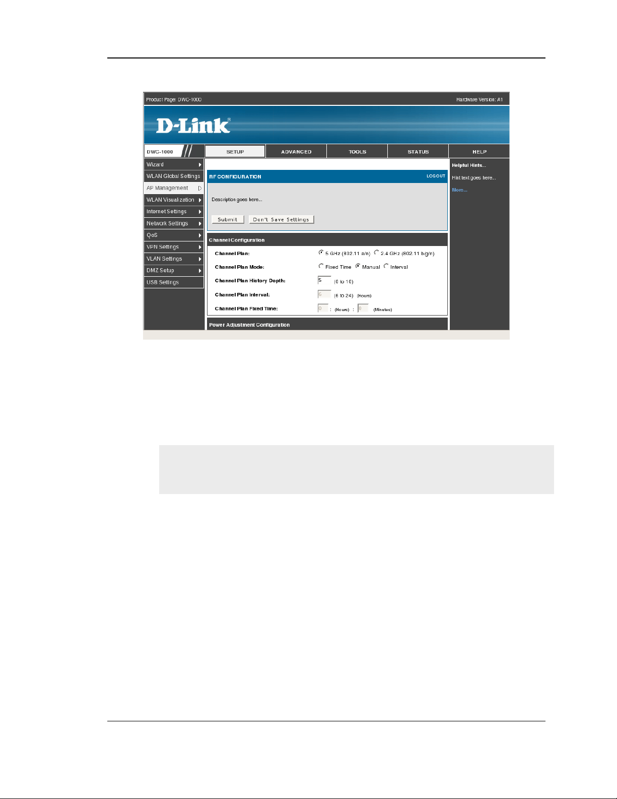
Wireless Controller User Manual
Figure 53: RF configuration
Channel Plan History Depth: The channel plan history lists the channels the
controller assigns each of the APs it manages after a channel plan is applied.
Entries are added to the history regardless of interval, time, or channel plan
mode. The number you specify in this field controls the number of iterations of
the channel assignment.
The APs changed in previous iterations cannot be assigned new channels in
the next iteration. This history prevents the same APs from being changed
time after time.
Channel Plan Interval: If you select the Interval channel plan mode, you can
specify the frequency at which the channel plan calculation and assignment
occurs. The interval time is in hours, and you can specify an interval that ranges
between every 6 hours to every 24 hours.
Channel Plan Fixed Time: If you select the Fixed Time channel plan mode, you
can specify the time at which the channel plan calculation and assignment
occurs. The channel plan calculation will occur once every 24 hours at the time
you specify.
Power Adjustment Mode: You can set the power of the AP radio frequency
transmission in the AP profile, the local database or in the RADIUS server. The
power level in the AP profile is the default level for the AP, and the power will
87
Page 89

Wireless Controller User Manual
not be adjusted below the value in the AP profile. The settings in the local
database and RADIUS server always override power set in the profile setting. If
you manually set the power, the level is fixed and the AP will not use the
automatic power adjustment algorithm. You can configure the power as a
percentage of maximum power, where the maximum power is the minimum of
power level allowed for the channel by the regulatory domain or the hardware
capability.
• Manual: In this mode, you run the proposed power adjustments manually from
the Manual Power Adjustments page.
• Interval: In this mode, the controller periodically calculates the power
adjustments and applies the power for all APs. The interval period begins when
you click Submit.
Power Adjustment Interval: This field determines how often the controller
runs the power adjustment algorithm. The algorithm runs automatically only if
you set the power adjustment mode to Interval.
This setting gets applied to both radios of the AP.
This page includes the following button:
• Submit —Updates the switch with the values you enter.
RF Management (Channel Plan History)
Setup > AP Management > RF Management > Channel Plan History
The wireless controller stores channel assignment information for the APs it
manages. The Cluster Controller that controls the cluster maintains the channel
history information for all controllers in the cluster. On the Cluster Controller, the
page shows information about the radios on all APs managed by controllers in the
cluster that are eligible for channel assignment and were successfully assigned a
new channel.
Channel Plan: The 5 GHz and 2.4 GHz radios use different channel plans, so
the controller tracks the channel history separately for each radio. The channel
information that displays on the page is only for the radio you select.
Operational Status: This field shows whether the controller is using the
automatic channel adjustment algorithm on the AP radios.
Last Iteration: The number in this field indicates the most recent iteration of
channel plan adjustments. The APs that received a channel adjustment in
88
Page 90

Wireless Controller User Manual
previous iterations cannot be assigned new channels in the next iteration to
prevent the same APs from being changed time after time.
Last Algorithm Time: Shows the date and time when the channel plan
algorithm last ran.
AP MAC Address: This table displays the channel assigned to an AP in an
iteration of the channel plan (Location, Radio,Iteration, Channel)
Figure 54: Channel Plan History
.
RF Management (Manual Channel Plan)
Setup > AP Management > RF Management > Manual Channel Plan
If you specify Manual as the Channel Plan Mode on the Configuration tab, the
Manual Channel Plan page allows you to initiate the channel plan algorithm. To
manually run the channel plan adjustment feature, select the radio to update the
channels on (5 GHz or 2.4 GHz) and click Start.
Channel Plan: The 5 GHz and 2.4 GHz radios use different channel plans, so
the controller tracks the channel history separately for each radio. The channel
information that displays on the page is only for the radio you select.
Channel plan algorithm (Current Status): Shows the Current Status of the plan,
which is one of the following states:
• No ne: The channel plan alg orithm has not been manually run since the last
controller reboot.
• Algorithm in Progress: The channel plan al go rithm is running.
89
Page 91

Wireless Controller User Manual
• Algorithm Complete: T he channel plan algor it hm has finished running.
A table displays to indicate proposed channel assignments. Each entry shows the
AP along with the current and new channel. To accept the proposed channel
change, click Apply. You must manually apply the channel plan for the
proposed assignments to be applied.
• Apply In Progre ss : The controller is applying the proposed channel plan and
adjusting the channel on the APs listed in the table.
• Appl y Co mplete: The algorithm and chan nel adjustment are co mp lete
Proposed Channel Assignments: If no APs appear in the table after the
algorithm is complete, the algorithm does not recommend any channel changes.
• Current Channel: Shows the current operating channel for the AP that the
algorithm recommends for new channel assignments.
• New Channel: Shows the proposed operating channel for the AP.
This page has the following button:
• Start: To initiate the channel plan algorithm...
Figure 55: Manual Channel Plan
.
90
Page 92

Wireless Controller User Manual
RF Management (Manual Power Adjustment Plan)
Setup > AP Management > RF Management > Manual Power Adjustment
Plan
If you select Manual as the Power Adjustment Mode on the Configuration tab, you
can manually initiate the power adjustment algorithm on the Manual Power
Adjustments page.
Current Status: Shows the Current Status of the plan, which is one of the
following states:
• None: T he power adjustment algorithm has not been manually run since the last
controller reboot.
• Algorithm In Progress: The power adjustment algorithm is running.
• Algorithm Complete: T he power adjustment algorithm has fi ni shed running.
• A table displays to indicate proposed power adjustments. Each entry shows the
AP along with the current and new power levels.
• Appl y In P rogress: The controller is adjusting the power levels that the APs use.
• Ap ply Complete: The algorit hm and power adjustment are co mp lete. AP MAC
Address Identifies the
AP MAC address: Identifies the AP MAC address.
Location: Identifies the location of the AP, which is set in the Valid AP database.
Radio Interface: Identifies the radio.
Old Power: Shows the earlier power level for the AP.
New Power: Shows the proposed power level for the AP.
This page includes the following button:
• Start: To initiate the power adjustment algorithm.
91
Page 93

Wireless Controller User Manual
Figure 56: Manual Power Adjustment Plan
Access Point Software Download
Setup > AP Management > Software Download
The wireless controller can upgrade software on the APs that it manages.
Server Address: Enter the IP address of the host where the upgrade file is
located. The host must have a TFTP server installed and running.
File Path: Enter the file path on the TFTP server where the software is located.
You may enter up to 96 characters.
File Name: Enter the name of the upgrade file. You may enter up to 32
characters, and the file extension .tar must be included.
Group Size: When you upgrade multiple APs, each AP contacts the TFTP
server to download the upgrade file. To prevent the TFTP server from being
overloaded, you can limit the number of APs to be upgraded at a time. In the
Group Size field, enter the number of APs that can be upgraded at the same
time. When one group completes the upgrade, the next group begins the process
Image Download Type: Type of the image to be downloaded, which can be one
of the following:
• All images ( img_dwl8600 and img_dwl3600/66 00)
• img_dwl8 600
• img_dwl3600/6600
92
Page 94

Wireless Controller User Manual
To download all images, make sure you specify the file path and file name for
both images in the appropriate File Path and File Name fields.
Managed AP: The list shows all the APs that the controller manages. If the
controller is the Cluster Controller, then the list shows the APs managed by all
controllers in the cluster. Each AP is identified by its MAC address, IP address,
and Location in the <MAC - IP - Location> format. To upgrade a single AP,
select the AP MAC address from the drop down list. To upgrade all APs, select
All from the top of the list. If All is selected, the Group Size field will limit the
number of simultaneous AP upgrades in order not to overwhelm the TFTP server
Figure 57: Access Point Software Download
Local OUI Database Summary
Setup > AP Management > Local OUI Database
To help identify AP and Wireless Client adapter manufacturers detected in the
wireless network, the wireless controller contains a database of registered
Organizationally Unique Identifiers (OUIs). This is a read-only list with over 10,000
registrations. From the Local OUI Database Summary page, you can enter up to 64
user-defined OUIs. The local list is searched first, so the same OUI can be located in
the local list as well as the read-only list.
OUI Value: Enter the OUI that represents the company ID in the format XX:XX:XX
where XX is a hexadecimal number between 00 and FF. The first three bytes of the
MAC address represents the company ID assignment.
93
Page 95

Wireless Controller User Manual
The first byte of the OUI must have the least significant bit set to 0. For
example 02:FF:FF is a valid OUI, but 03:FF:FF is not.
OUI Description: Enter the organization name associated with the OUI. The name
can be up to 32alphanumeric characters..
Figure 58: Local OUI Database
94
Page 96
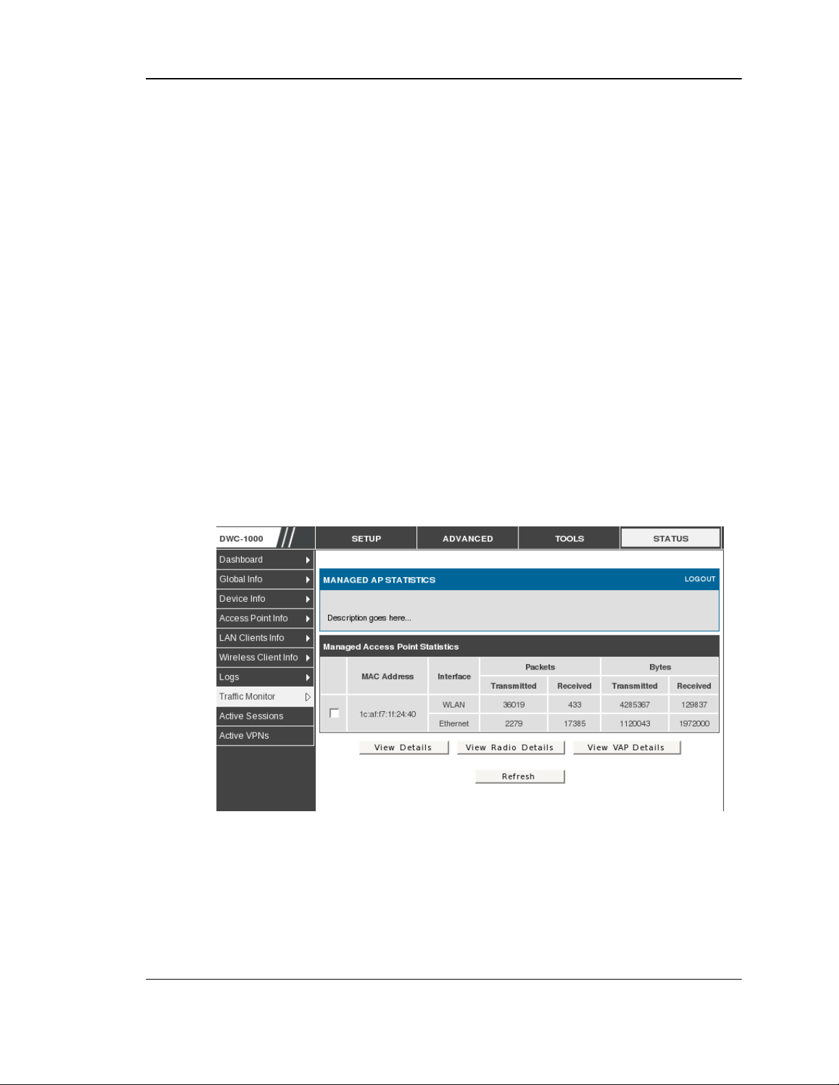
Wireless Controller User Manual
4.8 Associated Client Status/Statistics
Managed AP Statistics
Status > Traffic Monitor > Managed AP Statistics
The managed AP statistics page shows information about traffic on the wired and
wireless interfaces of the access point. This information can help diagnose network
issues, such as throughput problems. The following figure shows the Managed
Access Point Statistics page with a managed AP.
MAC Address: This field shows the MAC address of the client station
Interface: This field shows the interface type WLAN or Ethernet.
Packet Transmitted: This field shows the packet transmitted to the client station
Packet Received: This field shows the packet received to the client station
Bytes Transmitted: This field shows the bytes transmitted to the client station
Bytes Received: This field shows the bytes received to the client station
Figure 59: Managed AP Statistics
This page includes the following button:
• View Details — Shows detailed status information collected from the AP.
• View Rad io details — Shows detailed status for a radio interface
95
Page 97

Wireless Controller User Manual
• View V AP details — Shows summary information about the virtual access
points (VAPs) for the selected AP and radio interface on the APs that the
controller manages
• Refresh—Updates the page with the latest information
WLAN Assoicated Clients
Status > Traffic Monitor > Associated Clients Statistics > WLAN Associated
Clients
The wireless client can roam among APs without interruption in WLAN service.
The controller tracks the traffic the client sends and receives during the entire
wireless session while the client roams among APs that the controller manages. The
controller stores statistics about client traffic while it is associated with a single AP
as well as throughout the roaming session.
MAC Address: This field shows the MAC address of the client station
Packet Transmitted: This field shows the packet transmitted to the client station
Packet Received: This field shows the packet received to the client station
Bytes Transmitted: This field shows the bytes transmitted to the client station
Bytes Received: This field shows the bytes received to the client station
Figure 60: WLAN Associated Clients
This page includes the following button:
• Refresh—Updates the page with the latest information
• View Det ails — Shows detailed status associated client.
96
Page 98

Wireless Controller User Manual
Chapter 5. Securing the Private
Network
You can secure your network by creating and applying rules that your controller uses to
selectively block and allow inbound and outbound Internet traffic. You then specify
how and to whom the rules apply. To do so, you must define the following:
Services or traffic types (examples: web browsing, VoIP, other standard services
and also custom services that you define)
Direction for the traffic by specifying the source and destination of traffic; this is
done b y speci fying the ―From Zone‖ (LAN/WAN/DMZ) and ―To Zone‖
(LAN/WAN/DMZ)
Schedules as to when the controller should apply rules
Any Keywords (in a domain name or on a URL of a web page) that the controller
should allow or block
Rules for allowing or blocking inbound and outbound Internet traffic for specified
services on specified schedules
MAC addresses of devices that should not access the internet
Port triggers that signal the controller to allow or block access to specified services
as defined by port number
Reports and alerts that you want the controller to send to you
You can, for example, establish restricted-access policies based on time-of-day, web
addresses, and web address keywords. You can block Internet access by applications
and services on the LAN, such as chat rooms or games. You can block just certain
groups of PCs on your network from being accessed by the WAN or public DMZ
network.
5.1 Firewall Rules
Advanced > Firewall Settings > Firewall Rules
Inbound (WAN to LAN/DMZ) rules restrict access to traffic entering your network,
selectively allowing only specific outside users to access specific local resources. By
default all access from the insecure WAN side are blocked from accessing the secure
LAN, except in response to requests from the LAN or DMZ. To allow outside devices
to access services on the secure LAN, you must create an inbound firewall rule for
each service.
If you want to allow incoming traffic, you must make the controllers WAN port IP
address known to the public. This is called ―expo si ng your host.‖ How you make yo ur
address known depends on how the WAN ports are configured; for this controller you
97
Page 99

Wireless Controller User Manual
may use the IP address if a static address is assigned to the WAN port, or if your
WAN address is dynamic a DDNS (Dynamic DNS) name can be used.
Outbound (LAN/DMZ to WAN) rules restrict access to traffic leaving your network,
selectively allowing only specific local users to access specific outside resou rces. The
default outbound rule is to allow access from the secure zone (LAN) to either the
public DMZ or insecure WAN. On other hand the default outbound rule is to deny
access from DMZ to insecure WAN. You can change this default behaviour in the
Firewall Settings > Default Outbound Policy page. When the default outbound
policy is allow always, you can to block hosts on the LAN from accessing internet
services by creating an outbound firewall rule for each service.
Figure 61: List of Available Firewall Rules
5.2 Defining Rule Schedules
Tools > Schedules
Firewall rules can be enabled or disabled automatically if they are associated with a
configured schedule. The schedule configuration page allows you to define days of
the week and the time of day for a new schedule, and then this schedule can be
selected in the firewall rule configuration page.
All schedules will follow the time in the c ontroller‘s configured time zone. Refer to
the section on choosing your Time Zone and configuring NTP servers for more
information.
98
Page 100

Wireless Controller User Manual
Figure 62: List of Available Schedules to bind to a firewall rule
5.3 Configuring Firewall Rules
Advanced > Firewall Settings > Firewall Rules
All configured firewall rules on the controller are displayed in the Firewall Rules list.
This list also indicates whether the rule is enabled (active) or not, and gives a
summary of the From/To zone as well as the services or users that the rule affects.
To create a new firewall rules, follow the steps below:
1. View the existing rules in the List of Available Firewall Rules table.
1. To edit or add an outbound or inbound services rule, do the following:
To edit a rule, cl ic k the c heckbox next to the rule and click Edit to rea ch that rule‘s
configuration page.
To add a new rule, click Add to be ta ken to a new rule‘s co nfiguration pa ge. Once
created, the new rule is automatically added to the original table.
2. Chose the From Zone to be the source of originating traffic: either the secure LAN, public
DMZ, or insecure WAN. For an inbound rule WAN should be selected as the From Zone.
3. Choose the To Zone to be the destination of traffic covered by this rule. If the From Zone
is the WAN, the to Zone can be the public DMZ or secure LAN. Similarly if the From
Zone is the LAN, then the To Zone can be the public DMZ or insecure WAN.
4. Parameters that define the firewall rule include the following:
99
 Loading...