

Page 1
Re setting the DI-824VUP to the
Factory Default Settings
After you have tried other methods for troubleshooting your network, you
may choose to Reset the
DI-824VUP to the factory default settings.
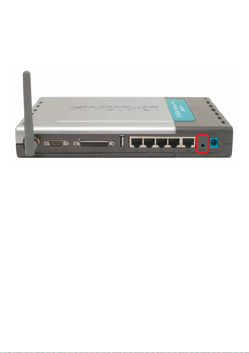
To hard-reset the D-Link DI-824VUP
do the following:
Locate the Reset button on the back of the DI-824VUP.
Use a paper clip to press the Reset button and
power on.
Hold for about 5 seconds (do not hold for too long)
and then release. (Or, release when the status
LEDflashes.)
After you have completed the above steps, the DI-
824VUP
will be reset to the fa ctory default settings.
to the Factory Default Settings, plea se
101
Page 2

Technical Specifications
Standards
IEEE 802.1 1b
IEEE 802.3
IEEE 802.3u 100BASE-TX Fast Ethernet
IEEE 802.1 1g
USB 1.1
VPN Pass Through Function
PPTP
L2TP
IPSec
LEDs
Power
WAN
LAN
WLAN
Status
COM
USB
LPT
Operating Temperature
Humidity
Power
Dimensions
Weight
Ports
32°F to 131°F ( 0°C to 55°C)
10-90%
5V DC / 2.5A
L = 9.25 inches (233mm)
W = 6.5 inches (165mm)
H = 1.375 inches (35mm)
~2.0oz. (907g)
4 x 10/100 LAN Ports (MDI/MDIX)
1 x 10/100 WAN Port (MDI/MDIX
1 COM Port (Dial-up Modem)
1 Parallel Port (DB25)
1 USB Port
102
Page 3

Frequently As ked Que stion s
Why can´t I access the Web-based configuration?
When entering the IP Address of the DI-824VUP (192.168.0.1), you are not
connecting to the Internet or have to be connected to the Internet. The device ha s the
utility built-in to a ROM chip in the device itself. Your computer must be on the same
IP subnet to connect to the web-based utility.
To resolve difficulties accessing a W eb utility, plea se follow the steps below.
Step 1
you do not get a solid link light, try using a different cable or connect to a different
port on the device, if possible. If the computer is turned off, the link light may not be
on.
V erify physical connectivity by checking f or solid link lights on the device. If
What type of cable should I be using?
The following connections require a Crossover Cable:
Computer to Computer
Computer to Uplink Port
Computer to Access Point
Computer to Print Server
Computer/XBOX/PS2 to D WL-810
Computer/XBOX/PS2 to D WL-900AP+
Uplink Port to Uplink Port (hub/switch)
Normal Port to Normal Port (hub/switch)
The following connections require a Straight-through Cable:
Computer to Residential Gateway/Router
Computer to Normal Port (hub/switch)
Access Point to Normal Port (hub/switch)
Print Server to Normal Port (hub/switch)
Uplink Port to Normal Port (hub/switch)
Rule of Thumb:
”If there is a link light, the cable is right.”
103
Page 4
Frequently Asked Questions (continued)
Why can´t I access the Web-based configuration? (continued)
What type of cable should I be using? (continued)
What´s the difference between a crossover cable and a straight-through
cable?
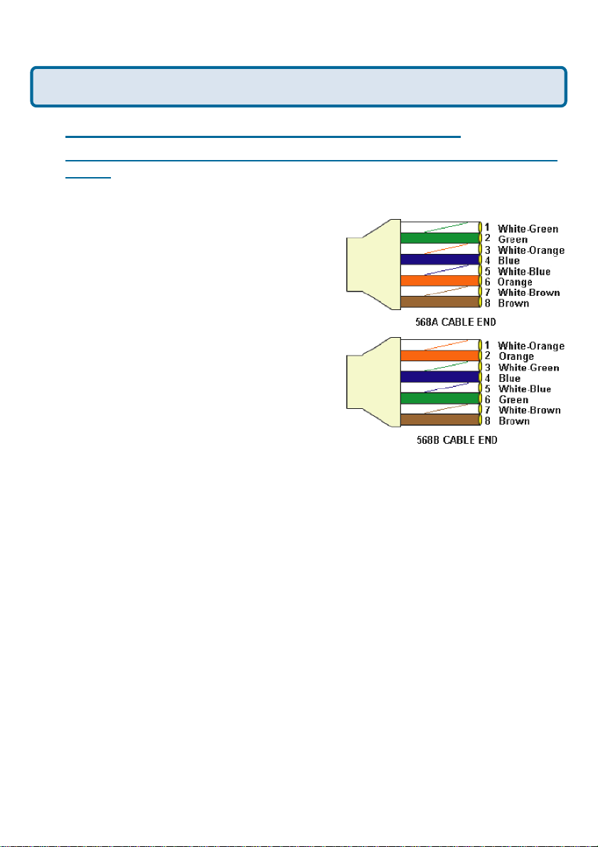
The wiring in crossover and straight-through cable s are different. The two types
of cable have different purposes for different
LAN configurations. EIA/TIA 568A/568B
define the wiring standards a nd allow for
two different wiring color codes a s
illustrated in the following diagra m.
*The wires with colored backgrounds may
have white stripes a nd may be denoted
that way in diagrams f ound elsewhere.
How to tell straight-through cable from
a crossover cable:
The main way to tell the difference
between the two cable types is to compare
the wiring order on the ends of the cable. If
the wiring is the same on both sides, it is
straight-through cable. If one side ha s opposite wiring, it is a crossover cable.
All you need to remember to properly configure the cables is the pinout order of
the two cable ends and the f ollowing rules:
A straight-through ca ble ha s identical ends
A crossover ca ble ha s different ends
It makes no function al difference which standard you f ollow for straight-through
cable ends, a s long as both ends are the sa me. You ca n start a crossover ca ble
with either standard as long a s the other end is the other sta ndard. It ma kes no
functional difference which end is which. The order in which you pin the cable is
important. Using a pattern other tha n what is specif ied in the above diagra m
could cause connection problems.
When to use a crossover cable and when to use a straight-through cable:
Computer to Computer – Crossover
Computer to an normal port on a Hub/Switch – Straight-through
Computer to an uplink port on a Hub/Switch – Crossover
Hub/Switch uplink port to another Hub/Switch uplink port – Crossover
Hub/Switch uplink port to another Hub/Switch normal port – Straight-through
104
Page 5
Frequently Asked Questions (continued)
Why can´t I access the Web-based configuration? (continued)
Step 2 Disable a ny Internet security software running on the computer . Software
firewalls like Zone Alarm, Bla ck Ice, Sygate, Norton Personal Firewall, etc. might
block access to the conf iguration pages. Check the help files included with your
firewall software for more information on disabling or configuring it.
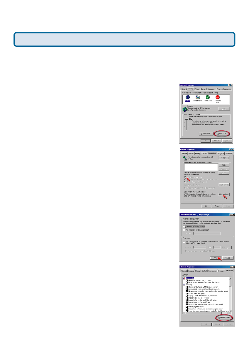
Step 3 Configure your Internet settings.
Go to Start > Settings > Control Panel. Double
click the Internet Options Icon. From the Security
tab, click the Default Level button to restore the
settings to their defaults.
Click to the Connection tab and set the dialup option to Never Dial a Connection. Click
the LAN Settings button.
Nothing should be checked. Click OK.
Go to the Advanced tab and click the
Restore Defaults button to restore
these settings to their fa cotry defaults.
Click OK. Go to the des ktop a nd close any open
windows.
105
Page 6
Frequently Asked Questions (continued)
Why can´t I access the Web-based configuration? (continued)
Step 4 Check your IP addre ss. Your computer must have an IP addre ss in the sa me
range of the device you are attempting to configure. Most D-Link devices use the
192.168.0.X range.
How can I find my IP Address in Windows 95, 98, or
ME?
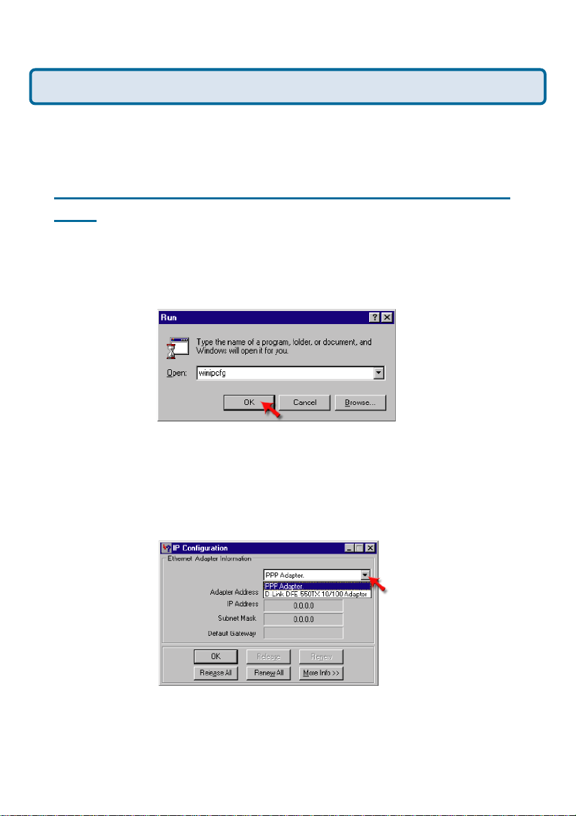
Step 1 Click on Start, then click on Run.
Step 2 The Run Di alogue Box will appear. T ype winipcfg in the text field and click
OK.
Step 3 The IP Configuration window will a ppear , displaying your Ethernet
Adapter Inf ormation.
Select your a da pter from the drop down menu.
If you do not see your a da pter in the drop down menu, your adapter is
not properly installed.
Step 4 After selecting your adapter , it will display your IP Address, subnet
mas k, and default gateway .
Step 5 Click OK to close the IP Configuration window
106
Page 7
Frequently Asked Question s (continued)
Why can´t I access the Web-based configuration? (continued)
Step 4 (continued) Che ck your IP a ddress. Your computer must have an IP Address
in the same ra nge of the device you are attempting to configure. Most D-Link devices
use the 192.168.0.X range.
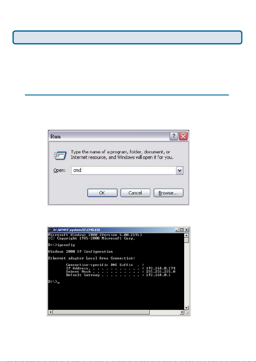
How can I find my IP Address in Windows 2000/XP?
Step 1 Click on Start and select Run.
Step 2 T ype cmd then click OK.
Step 3 From the Command Prompt, enter ipconfig. It will return your IP
Address, subnet ma sk, and default gateway
Step 4 T ype exit to close the command prompt.
107
Page 8
Frequently Asked Question s (continued)
Why can´t I access the Web-based configuration? (continued)
Step 4 (continued) Check your IP addre ss. Your computer must have a n IP addre ss
in the same ra nge of the device you are attempting to configure. Most D-Link devices
use the 192.168.0.X range.
Make sure you ta ke note of your computer´s Default Gateway IP Address. The Default
Gateway is the IP Address of the D-Link Router . By default, it should be 192.168.0.1.
How can I assign a Static IP Address in Windows XP?
Step 1
Click on Start > Control Panel > Network and Internet Connections >
Network connections.
Step 2 See
Step 2 for Windows 2000 a nd continue from there.
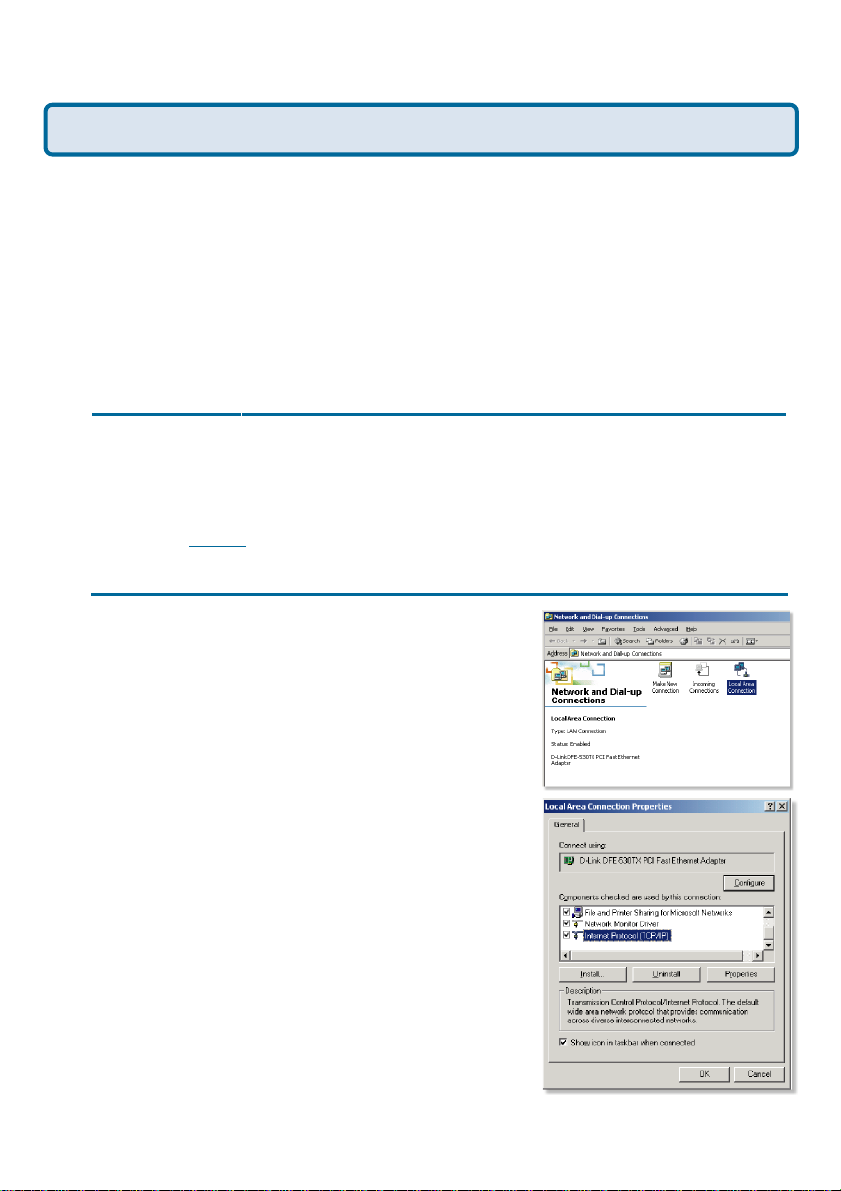
How can I assign a Static IP Addre ss in Windows 2000?
Step 1 Right-click on My Network
Places and select Properties.
Step 2 Right-click on the Local
Area Connection which represents
your network card and select
Properties.
Highlight Internet Protocol (TCP/
IP) and click Properties.
108
Page 9
Frequently Asked Questions (continued)
Why can´t I access the Web-based configuration? (continued)
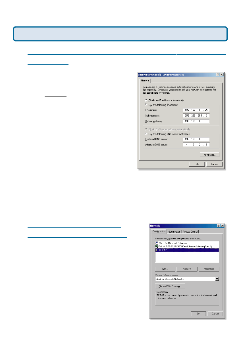
How can I assign a Static IP Address in Windows 2000?
(continued)
Click Use the following IP Address and
enter an IP Address that is on the same
subnet as the LAN IP address on your
router.
address is 192.168.0.1, ma ke your IP
address 192.168.0.X where X = 2-99.
Make sure that the number you choose is
not in use on the network.
Set the Default Gateway to be the same
a s the LAN IP addre ss of your router
(192.168.0.1).
Set the Preferred DNS server to be the
same as the LAN IP addre ss of your
router (192.168.0.1).
Example: If the router´s LAN I P
The Alternate DNS server is not needed or enter a DNS server from your ISP.
Click OK twice. You may be a sked if you wa nt to reboot your computer. Click
Yes.
How can I assign a Static IP
Address in Windows 98/Me?
Step 1 From the desktop, right-click on the
Network Neigborhood icon (Win ME - My
Network Places) a nd select Properties
Highlight TCP/IP and click the Properties
button. If you have more than one ad apter ,
then there will be a TCP/IP “Binding” for
each a da pter . Highlight TCP/IP > (your
network adapter) and then click
Properties.
109
Page 10
Frequently Asked Questions (continued)
Why can´t I access the Web-based configuration? (continued)
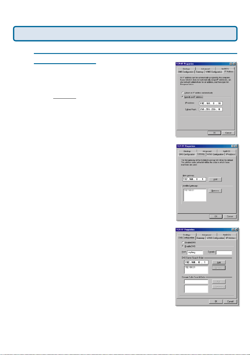
How can I assign a Static IP Address in Windows 98/
Me? (continued)
Step 2 Click Specify an IP Address.
Enter in an IP Address that is on the sa me
subnet as the LAN IP Addre ss on your router .
Example: If the router´s LAN I P Addre ss is
192.168.0.1, make your IP Address
192.168.0.X where X is between 2-99. Make
sure that the number you choose is not in
use on the network.
Step 3 Click on the Gateway tab.
Enter the LAN IP Addre ss of your router
here (192.168.0.1).
Click Add when finished.
Step 4 Click on the DNS Configuration tab.
Click En able DNS. T ype in a Host (ca n be
any word). U nder DNS server search order,
enter the LAN IP Address of your router
(192.168.0.1). Click Add.
Step 5 Click OK twice.
When prompted to reboot your computer,
click Yes.
After you reboot, the computer will now have
a static, private IP Address.
Step 5 Access the W eb ma nagement. Open your Web
browser and enter the IP Address of your D-Link device in
the address bar . This should open the log-in page for the
web management. Follow in structions to log in a nd complete the configuration.
110
Page 11

Frequently Asked Questions (continued)
How can I setup my DI-824VUP to work with a ca ble modem
connection?
Dynamic Cable connection
(i.e. Cox, Adelphi a, Rogers, Roadrunner , Charter , and Comca st).
Note: Please configure the router with the computer that was la st connected directly
to the cable modem.
Step 1 Log into the W eb based configuration by typing in the IP Address of the router
(default:192.168.0.1) in your web browser. The userna me is admin (all lowerca se) an d
the password is blank (nothing).
Step 2 Click the Home tab and click the
WAN button. Dyna mic IP address is the default
value, however, if Dyna mic IP address is not
selected as the WAN type, select Dynamic IP
address by clicking on the radio button. Click
Clone Ma c a ddress. Click on Apply and then
Continue to save the changes.
+
111
Page 12
Frequently Asked Question s (continued)
How can I setup my DI-824VUP to work with a cable mode m
connection? (continued)
Step 3 Power cycle the cable modem and router:
First turn the cable modem off. Then turn the router off Leave them off for 2 minutes.**
Next turn the cable modem on. Wait until you get a solid cable light on the cable
modem, and then turn the router on. Wait 30 se conds.
** If you have a DCM-201modem, leave of f for at lea st 5 minutes.
Step 4 Follow step 1 again and log ba ck into the web configuration. Click the Status
tab a nd click the Device Info button. If you do not alrea dy have a public IP Address
under the WAN heading, click on the DHCP Renew and Continue buttons.
Static Cable Connection
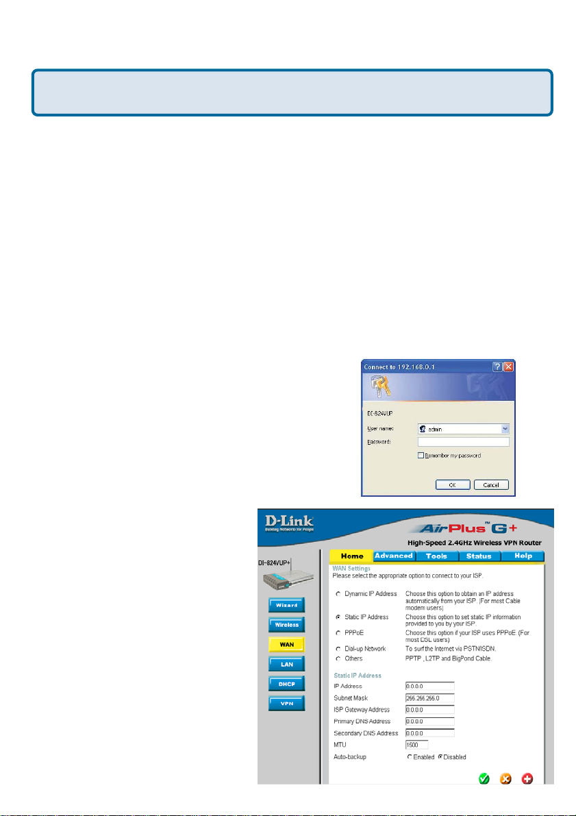
Step 1 Log into the W eb-ba sed configuration by typing in the IP address of the router
(default:192.168.0.1) in your W eb browser. The userna me is admin (all lowerca se) a nd
the password is bla nk (empty).
Step 2 Click the Home tab and click the WAN
button. Select Static IP Address and enter your
static settings obtained from the ISP in the fields
provided.
If you do not know your settings, you must
contact your ISP.
Step 3 Click on Apply and then
click Continue to save the cha nges.
Step 4 Click the Status tab and
click the Device Info button. Your
IP Addre ss information will be
displayed under the WAN heading.
+
112
Page 13

Frequently Asked Question s (continued)
How can I setup my DI-824VUP to work with Earthlink DSL or any
PPPoE connection?
Make sure you disable or uninstall a ny PPPoE software such as WinPoet or Enternet
300 from your computer or you will not be able to connect to the Internet.
Step 1 Upgrade Firmware if needed.
(Plea se visit the D-Link tech support website at: http://support.dlink.com f or the latest
firmware upgrade information.)
Step 2 T a ke a paperclip and perf orm a hard reset. With the unit on, use a pa percli p
and hold down the reset button on the ba ck of the unit f or 10 seconds. Release it and
the router will recycle, the lights will blink, and then sta bilize.
Step 3 After the Router sta bilizes, open your browser and enter 192.168.0.1 into the
address window a nd hit the Enter key . When the pa ssword di alog box a ppears, enter
the userna me admin a nd leave the pa ssword blank. Click OK.
If the password di alog box does not come up repeat Ste p 2.
Note: Do not run Wizard.
Step 4 Click on the WAN tab on left-hand side of the screen. Select PPPoE.
Step 5 Select Dynamic PPPoE (unless your ISP supplied you with a static IP
Address).
Step 6 In the userna me field enter ELN/username@earthlink.net a nd your
pa ssword, where userna me is your own userna me.
For SBC Global users, enter username@sbcglobal.net.
For Ameritech users, enter username@ameritech.net.
For BellSouth users, enter username@bellsouth.net.
For Mindspring users, enter username@mindspring.com.
For most other ISPs, enter username.
Step 7 Maximum Idle Time should be set to zero. Set MTU to 1492, unless
specified by your ISP, and set Autoreconnect to Enabled.
Note: If you experience problems accessing certain websites a nd/or email issues,
plea se set the MTU to a lower number such a s 1472, 1452, etc. Conta ct your ISP f or
more information and the proper MTU setting f or your connection.
113
Page 14
Frequently Asked Question s (continued)
How can I setup my DI-824VUP to work with Earthlink DSL or any
PPPoE connection? (continued)
Step 8 Click Apply. When prompted, click Continue. Once the screen refreshes,
unplug the power to the D-Link Router.
Step 9 Turn off your DSL modem f or 2-3 minutes. T urn ba ck on. Once the modem
has e stablished a link to your ISP, plug the power back into the D-Link Router. W ait
about 30 seconds and log ba ck into the router .
Step 10 Click on the Status tab in the web configuration where you can view the
device info. U nder WAN, click Connect. Click Continue when prompted. Y ou should
now see that the device info will show an IP Address, verifying that the device ha s
connected to a server and ha s been a ssigned a n IP Address.
Can I use my DI-824VUP to share my Internet connection provided by
AOL DSL Plus?
In most case s yes. AOL DSL Plus may use PPPoE for authentication bypassing the
client software. If this is the case, then our routers will work with this service. Ple ase
contact AOL if you are not sure.
T o set up your router:
Step 1 Log into the W eb-ba sed configuration (192.168.0.1) a nd configure the W AN
side to use PPPoE.
Step 2 Enter your screen na me followed by @aol.com f or the user na me. Enter your
AOL pa ssword in the pa ssword box.
Step 3 Y ou will have to set the MTU to 1400. AOL DSL does not allow for anything
higher than 1400.
Step 4 Apply settings.
Step 5 Recycle the power to the modem for 1 minute a nd then re cycle power to the
router. Allow 1 to 2 minutes to connect.
If you connect to the Internet with a different Internet Service Provider and wa nt to use
the AOL software, you ca n do that without configuring the router’s firewall settings.
Y ou need to configure the AOL software to connect using TCP/IP.
Go to http://www.aol.com for more specific configuration information of their software.
114
Page 15
Frequently Asked Question s (continued)
I have two DI-824VUP Routers, how can I set them up to work with
each other?
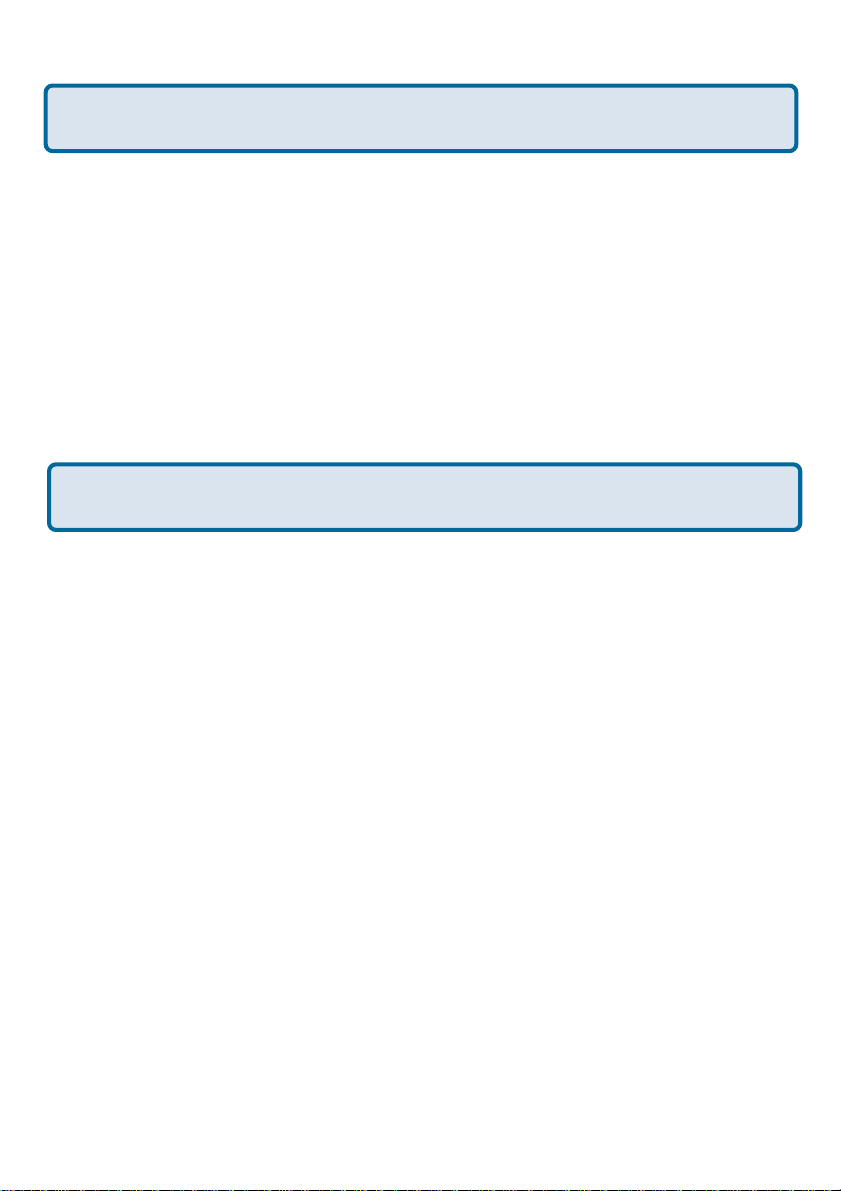
Step 1 Log into the web based
configuration of the router by typing in
the IP address of the router (default:
192.168.0.1) in your web browser. By
default the userna me is admin and there
is no password.
Step 2 Click the VPN button on the left
column, select the checkbox to Enable
the VPN, and then in the box next to Max.
number of tunnels, enter the maximum
numbers of VPN tunnels that you would
like to have connected.
+
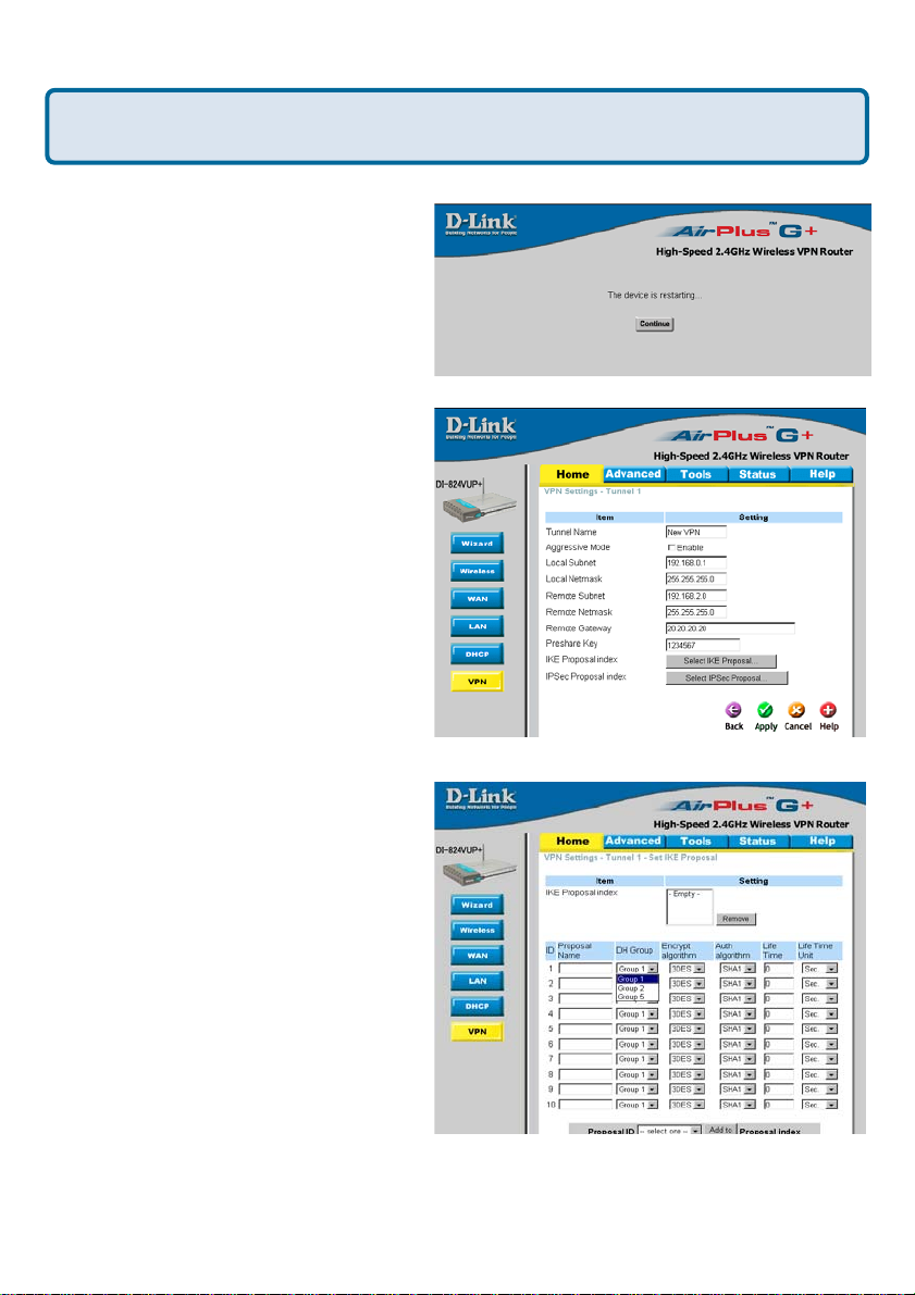
Step 3 In the space provided, enter the
Tunnel Na me for ID number 1, select IKE,
and then click More.
115
Page 16
Frequently Asked Question s (continued)
I have two DI-824VUP Routers, how can I set them up to work with
each other?(continued)
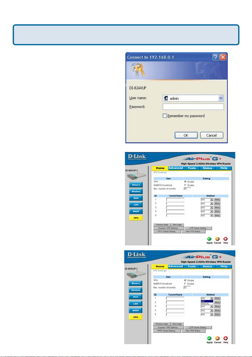
Step 4 In the Local Subnet and Local
Netmask fields enter the network
identifier for the local
and the corresponding subnet ma s k.
Step 5 In the Remote Subnet and
Remote Netmask fields enter the
network identifier for the remote DI824VUP´s LAN a nd the corresponding
subnet mask.
DI-824VUP´s LAN
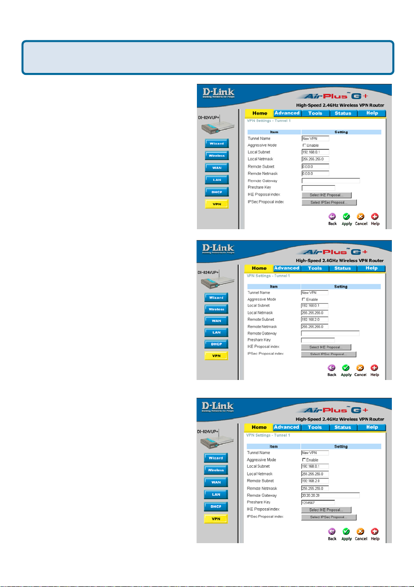
Step 6 In the Remote Gateway field
enter the WAN IP address of the remote
DI-824VUP and in the Preshare Key
field, enter a key which must be exa ctly
the same as the Preshare Key that is
configured on the remote DI-824VUP
Step 7 Click Apply .
.
116
Page 17
Frequently Asked Questions (continued)
I have two DI-824VUP Routers, how can I set them up to work with
each other? (continued)
Step 8 The device will restart. Click on
the Continue button.
Step 9 Click on Select IKE Proposal.
Step 10 Enter a name f or proposal ID
number 1 and select Group 1, 2, or 5
from the DH Group dropdown menu.
117
Page 18

Frequently Asked Questions (continued)
I have two DI-824VUP Routers, how can I set them up to work with
each other? (continued)
Step 11 Select DES or 3DES as the
Encryption Algorithm.
Step 12 Select SHA-1 or MD5 as the
Authentication Algorithm.
Step 13 Enter a Lifetime value of 2800
and then either select Sec. or KByte as
the unit for the lifetime value.
118
Page 19

Frequently Asked Question s (continued)
I have two DI-808HV Routers,how can I set them up to work with each
other? (continued)
Step 14 Select 1 out of the Proposal ID
dropdown menu and click Add To, which
will add the proposal that was just
configured to the IKE Proposal Index.
Click Apply.
Step 15 The device will restart. Click
on the Continue button.Then click Back.
Step 16 Click on Select IPSec
Proposal.
119
Page 20

Frequently Asked Questions (continued)
I have two DI-824VUP Routers, how can I set them up to work with
each other?(continued)
Step 17 Enter a name f or proposal ID
number 1 and select Group 1, 2, 5, or
None from the DH Group dropdown
menu.
Step 18 Select ESP or AH as the
Encapsulation Protocol.
Step 19 Select DES or 3DES as the
Encryption Algorithm.
120
Page 21

Frequently Asked Question s (continued)
I have two DI-824VUP Routers, how can I set them up to work with
each other? (continued)
Step 20 Select SHA-1, MD5, or None
a s the Authentication Algorithm.
Step 21 Enter a Lifetime value a nd then
either select Sec. or KB as the unit for
the lifetime value.
Step 22 Select 1 out of the Proposal ID
dropdown menu and click Add To, which
will add the proposal that was just
configured to the IPSec Proposal Index.
Click Apply a nd the device will re start.
121
Page 22

Frequently Asked Question s (continued)
I have two DI-824VUP Routers, how can I set them up to work with
each other? (continued)
Step 23 Follow these instructions to configure your other DI-824VUP using the
exa ct same settings for the IKE Proposal and the IPSe c Proposal. Also make sure
that Step 4 is configured to reflect the LAN settings f or what is now the Local DI824VUP
what is now the remote DI-824VUP
Step 24 T o esta blish the connection, open a comma nd prompt a nd ping an IP
address of a computer on the remote LAN. Once you receive replies the tunnel has
been established.
How can I set up my DI-824VUP to work with a DI-804V or DI-804HV
Router?
Y ou need to first conf igure your DI-824VUP router .
Step 1 Log into the Web-based
configuration of the router by typing in
the IP address of the router (default:
192.168.0.1) in your web browser. By
default the username is “admin” and
there is no pa ssword.
and that Steps 5 & 6 are configured to reflect the Subnet a nd W AN IP of
.
+
Step 2 Click the VPN button on the left
column, select the checkbox to Enable
the VPN, and then in the box next to
Max. number of tunnels, enter the
maximum numbers of VPN tunnels that
you would like to have connected.
122
Page 23

Frequently Asked Question s (continued)
How can I set up my DI-824VUP to work with a DI-804V or DI-804HV
Router? (continued)
Step 3 In the space provided, enter the
Tunnel Name f or ID number 1, select IKE,
and then click More.
Step 4 In the Local Subnet and Local
Netmask fields enter the network
identifier for
corresponding subnet mas k.
DI-824VUP’s LAN a nd t he
Step 5 In the Remote Subnet and
Remote Netmask fields enter the
network identifier for the DI-804V or DI804HV’s LAN and the corresponding
subnet mask. Click Apply.
123
Page 24

Frequently Asked Questions (continued)
How can I set up my DI-824VUP to work with a DI-804V or DI-804HV
Router? (continued)
Step 6 The device will restart. Click on
the Continue button.
Step 7 In the Remote Gateway field
enter the WAN IP address of the remote
DI-804V or DI-804HV and in the Pre share
Key field, enter a key which must be
exactly the same as the Preshare Key
that is configured on the DI-804V or DI804HV.
Step 8 Click Apply and then click on
Select IKE Proposal.
Step 9 Enter a name for proposal ID
number 1 and select Group 2 from the
DH Group drop down menu.
Step 10 Select 3DES a s the
Encryption Algorithm a nd SHA-1 a s the
Authentication Algorithm.
Step 11 Enter a Lifetime value of 28800
and then select Sec. as the unit for the
lifetime value.
124
Page 25

Frequently Asked Question s (continued)
How can I set up my DI-824VUP to work with a DI-804V or DI-804HV
Router? (continued)
Step 12 Select 1 out of the Proposal ID
dropdown menu and click Add To, which
will add the proposal that was just
configured to the IKE Proposal Index.
Click Apply.
Step 13 The device will restart. Click
on the Continue button.
Step 14 Click Back and click on
Select IPSec Proposal.
Step 15 Enter a na me for proposal ID
number 1 and select None from the DH
Group drop-down menu.
Step 16 Select ESP as the
Encapsulation Protocol.
125
Page 26

Frequently Asked Questions (continued)
How can I set up my DI-824VUP to work with a DI-804V or DI-804HV
Router? (continued)
Step 17 Select 3DES as the
Encryption Algorithm a nd MD5 a s the
Authentication Algorithm. Click Apply.
Step 18 Enter a Lifetime value of 3600
and then select Sec. as the unit for the
lifetime value.
Step 19 Select 1 out of the Proposal
ID dropdown menu a nd click Add To,
which will add the proposal that wa s
just configured to the IPSec Proposal
Index. Click Apply . The device will
restart. Click on the Continue button.
126
Page 27

Frequently Asked Question s (continued)
How can I set up my DI-824VUP to work with a DI-804V or DI-804HV
Router? (continued)
Next you need to configure the DI-804V or DI-804HV Router .
Step 1 Access the router’s web configuration by entering the router’s IP a ddress in
your web browser. The default IP address is 192.168.0.1. Login using your pa ssword.
The default userna me is “admin” an d the password is bla nk.
Step 2 Click on Basic Setup a nd then sele ct Device IP Settings on the left.
Step 3 Change the LAN IP address so
that it is on a different subnet than the
LAN of the
Step 4 Click Next until you reach the
Save & Restart screen. Click Save &
restart and then click Basic Setup once
until the unit ha s rebooted.
Step 5 Click on VPN Settings.
DI-824VUP.
Step 6 Name your VPN connection a nd
click ADD.
Step 7 In Remote IP Network and
Remote IP Netmask fields enter the
network identifier and corresponding
subnet ma sk of the
Step 8 In the Remote Gateway IP field
enter the WAN IP address of the DI824VUP and make sure that the
Network Interface is set to WAN
Ethernet.
Step 9 V erify that Secure Association is set to IKE a nd that Perfect Forward Secure is
Disabled.
DI-824VUP´s LAN.
127
Page 28

Frequently Asked Question s (continued)
How can I set up my DI-824VUP to work with a DI-804V or DI-804HV
Router? (continued)
Step 10 Verify the Encryption Protocol
is set to 3DES and enter in your
Preshared Key .
Note: The Preshared Key needs to be
identical to the one configured on the
DI-824VUP.
Step 11 Leave the Key Life and IKE Life
Time value s at their default levels and click
SAVE.
Step 12 Click Next and then click on
Save & Restart.
After you have configured both routers, you need to establish a connection.
Step 1 Open a command prompt and
from a computer on the internal LAN of
the
DI-824VUP and ping the IP a ddress
of a computer that is on the internal LAN
of the DI-804V or DI-804HV , or vice versa.
Step 2 Once you begin to receive
replies, the VPN connection has been
established.
128
Page 29

Frequently Asked Questions (continued)
How can I set up my DI-824VUP to work with a DI-804V or DI-804HV
router? (continued)
Step 3 To view the Status of the VPN
on the DI-804V or DI-804HV, click on
Device Status.
Step 4 From the Device Status screen
click on VPN Status.
Step 5 When the VPN ha s been
established the Status will be Active.
How can I set up my DI-824VUP to work with a DFL-300 Firewall?
Y ou need to first conf igure your DI-824VUP router .
Step 1 Log into the web ba sed configuration of the router by typing in the IP address of
the router (default: 192.168.0.1) in your web browser. By default the usern ame is “admin”
and there is no pa ssword.
Step 2 Click the VPN button on the left column, select the checkbox to Enable the
VPN, and then in the box next to Max. number of tunnels, enter the maximum numbers
of VPN tunnels that you would like to have connected.
129
Page 30

Frequently Asked Question s (continued)
How can I set up my DI-824VUP to work with a DFL-300 Firewall?
(continued)
Step 3 In the space provided, enter the
Tunnel Na me for ID number 1, select IKE,
and then click More.
Step 4 In the Local Subnet and Local
Netmask fields enter the network
identifier for
corresponding subnet mas k.
DI-824VUP´s LAN a nd the
Step 5 In the Remote Subnet and
Remote Netmask fields enter the
network identifier for the DFL-300´s
Internal interfa ce and the corresponding
subnet mask.
130
Page 31

Frequently Asked Question s (continued)
How can I set up my DI-824VUP to work with a DFL-300 Firewall?
(continued)
Step 6 In the Remote Gateway field
enter the WAN IP address of the remote
DFL-300 and in the Preshared Key field,
enter a key which must be exactly the
same as the Preshared Key that is
configured on the DFL-300.
Step 7 Click Apply. The device will
restart. Click on the Continue button and
then click on Select IKE Proposal.
Step 8 Enter a na me for proposal ID number 1 and select Group 2 from the DH Group
dropdown menu.
Step 9 Select 3DES as the Encryption Algorithm and SHA-1 as the Authentication
Algorithm.
Step 10 Enter a Lifetime value of 28800
and then select Sec. as the unit for the
lifetime value.
131
Page 32

Frequently Asked Question s (continued)
How can I set up my DI-824VUP to work with a DFL-300 Firewall?
(continued)
Step 11 Select 1 out of the Proposal
ID dropdown menu and click Add To,
which will add the proposal that wa s just
configured to the IKE Proposal Index.
Click Apply . The device will re start. Click
on the Continue button and then click
Back.
Step 12 Click on Select IPSec
Proposal.
Step 13 Enter a na me for proposal ID
number 1 and select None from the DH
Group dropdown menu.
Step 14 Select ESP as the Encapsulation Protocol.
Step 15 Select 3DES as the Encryption Algorithm and MD5 as the Authentication
Algorithm.
Step 16 Enter a Lifetime value of 28800
and then select Sec. as the unit for the
lifetime value.
132
Page 33

Frequently Asked Question s (continued)
How can I set up my DI-824VUP to work with a DFL-300 Firewall?
(continued)
Step 17 Select 1 out of the Proposal ID
dropdown menu and click Add To, which
will add the proposal that was just
configured to the IPSec Proposal Index.
Click Apply and then click Restart.
Step 18 The device will restart. Click
on the Continue button.
Next you need to configure the DFL-300 firewall.
Step 1 Access the configuration
screen of the DFL-300 by opening a
web browser such a s Internet Explorer
and type the IP a ddress of the DFL300 in the address bar (192.168.1.1).
Step 2 Enter the userna me (admin)
and the pa ssword (admin). Click OK.
Step 3 Click on Configuration and ta ke
note of the IP address that your ISP has
assigned you.
133
Page 34

Frequently Asked Questions (continued)
How can I set up my DI-824VUP to work with a DFL-300 Firewall?
(continued)
Step 4 Click on Policy and verify that
you have an Outgoing policy configured.
If not, click on New Entry, accept the
default values, and click OK.
Step 5 Click on VPN and then click
New Entry .
Step 6 Give the V PN connection a name with no spaces.
Step 7 Enter the network identifier and subnet ma s k of the Internal interfa ce.
Step 8 In the To Destination section, sele ct either Remote Gateway—Fixed IP or Remote
Gateway—Dynamic IP . Enter the W AN IP a ddress of the DI-824VUP
Fixed IP is selected.
Step 9 Enter the network identifier corresponding subnet ma sk of the
LAN.
Step 10 Enter a Preshared Key . The Pre shared Key needs to be identical to the one
configured on the
Step 11 Select Data Encryption a nd Authentication as the Enca psulation a nd click OK.
DI-824VUP.
if Remote Gateway—
DI-824VUP´s
134
Page 35

Frequently Asked Question s (continued)
How can I set up my DI-824VUP to work with a DFL-300 Firewall?
(continued)
After you have configured both the router and f irewall, you need to establish a
connection.
Step 1 Open a command prompt and
from a computer connected to the Internal interfa ce of the DFL-300 a nd ping the
IP address of a computer that is on the
internal LAN of the DI-824VUP
versa.
Step 2 Once you begin to receive replies, the VPN connection ha s been established.
, or vice
135
Page 36

Frequently Asked Question s (continued)
How do I open ports on my DI-824VUP?
T o allow traff ic from the internet to
enter your local network, you will need
to open up ports or the router will
block the request.
Step 1 Open your W eb browser and
enter the IP Addre ss of your D-Link
router (192.168.0.1). Enter userna me
(admin) and your pa ssword (bla nk by
default).
Step 2 Click on Advanced on top
and then click Virtual Server on the
left side.
Step 3 Check Enabled to activate
entry.
Step 4 Enter a na me for your virtual server entry .
Step 5 Next to Private IP, enter the IP Address of the computer on your local
network that you want to allow the incoming service to.
Step 6 Choose Protocol T ype - either TCP, UDP, or both. If you are not sure, select
both.
Step 7 Enter the port information next to Private Port and Public Port. The private
and public ports are usually the same. The public port is the port seen from the WAN
side, and the private port is the port being used by the application on the computer
within your local network.
Step 8 Enter the Schedule information.
Step 9 Click Apply a nd then click Continue.
Note: Make sure DMZ host is disabled. If DMZ is enabled, it will disable all Virtual
Server entries.
Because our routers use NA T (Network Address T ranslation), you ca n only open a
specific port to one computer at a time. For exa mple: If you have 2 web servers on
your network, you cannot open port 80 to both computers. You will need to configure 1
of the web servers to use port 81. Now you ca n open port 80 to the first computer a nd
then open port 81 to the other computer.
136
Page 37

Frequently Asked Question s (continued)
What is DMZ?
Demilitarized Zone:
In computer networks, a DMZ (demilitarized zone) is a computer host or small
network inserted a s a neutral zone between a company´s private network a nd the
outside public network. It prevents outside users from getting direct access to a server
that has compa ny data. (The term comes from the geogra phic buffer zone that wa s set
up between North Kore a and South Korea f ollowing the UN police a ction in the early
1950s.) A DMZ is a n optional and more se cure a pproach to a firewall a nd effe ctively
acts as a proxy server as well.
In a typical DMZ configuration f or a small company, a separate computer (or host in
network terms) receives requests from users within the private network f or acce ss to
W eb sites or other compa nies a ccessible on the public network. The DMZ host then
initiates session s for these requests on the public network. However , the DMZ host is
not able to initiate a session ba ck into the private network. It ca n only f orward pa ckets
that have already been requested.
Users of the public network outside the company ca n a ccess only the DMZ host. The
DMZ may typically also have the company´s Web pages so these could be served to
the outside world. However, the DMZ provides a ccess to no other compa ny data. In the
event that an outside user penetrated the DMZ hosts security , the W eb pages might
be corrupted but no other company information would be exposed. D-Link, a lea ding
maker of routers, is one compa ny that sells products designed for setting up a DMZ
How do I configure the DMZ Host?
The DMZ fe ature allows you to forward all incoming ports to one computer on the local
network. The DMZ, or Demilitarized Zone, will allow the specif ied computer to be
exposed to the Internet. DMZ is useful when a certain a pplication or ga me does not
work through the firewall. The computer that is configured f or DMZ will be completely
vulnerable on the Internet, so it is suggested that you try opening ports from the
Virtual Server or Firewall settings before using DMZ.
Step 1 Find the IP a ddress of the computer you want to use as the DMZ host.
T o find out how to locate the IP Addre ss of the computer in Windows XP/2000/ME/9x
or Macintosh operating systems ple ase refer to Step 4 of the first question in this
section (Frequently Asked Questions).
137
Page 38

Frequently Asked Questions (continued)
How do I configure the DMZ Host? (continued)
Step 2 Log into the web based conf iguration
DI-624
of the router by typing in the IP Address of the
router (default:192.168.0.1) in your web
browser. The userna me is admin (all
lowercase) a nd the pa ssword is bla nk (empty).
+
Step 3 Click the Advanced tab and then click on the DMZ button. Sele ct Enable
and type in the IP Address from step 1.
Step 4 Click Apply
and then Continue to
save the changes.
Note: When DMZ is
enabled, Virtual Server
settings will still be
effective. Remember ,
you cannot f orward the
same port to multi ple
IP Addresse s, so the
Virtual Server settings
will take priority over
DMZ settings.
138
Page 39

Frequently Asked Question s (continued)
How do I open a range of ports on my DI-824VUP using Firewall rules?
Step 1 Access the router’s web configuration by entering the router’s IP Address in
your web browser. The default IP Address is 192.168.0.1. Login using your pa ssword.
The default userna me is “admin” and the pa ssword is blank.
If you are having difficulty accessing web ma n agement, plea se see the f irst question
in this section.
Step 2 From the web management Home page, click the Advanced ta b then click
the Firewall button.
Step 3 Click on
Enabled and type in a
na me for the new rule.
Step 4 Choose WAN
a s the Source and
enter a range of IP
Addresses out on the
internet that you would
like this rule applied
to. If you would like
this rule to allow all
internet users to be
able to a ccess these
ports, then put an
Asterisk in the first
box and leave the
second box empty.
Step 5 Select LAN a s the Destination and enter the IP Address of the computer on
your local network that you want to allow the incoming service to. This will not work
with a range of IP Addresse s
Step 6 Enter the port or range of ports that are required to be open f or the incoming
service.
Step 7 Click Apply a nd then click Continue.
Note: Make sure DMZ host is disabled.
Because our routers use NA T (Network Address T ran slation), you can only open a
specific port to one computer at a time. For exa mple: If you have 2 web servers on
your network, you cannot open port 80 to both computers. You will need to configure 1
of the web servers to use port 81. Now you ca n open port 80 to the first computer a nd
then open port 81 to the other computer.
.
139
Page 40

Frequently Asked Questions (continued)
What are virtual servers?
A Virtual Server is def ined a s a service port, a nd all requests to this port will be
redirected to the computer specified by the server IP. For example, if you have a n FTP
Server (port 21) at 192.168.0.5, a W eb server (port 80) at 192.168.0.6, and a VPN
(port 1723) server at 192.168.0.7, then you need to specify the following virtual server
mapping ta ble:
Server Port
Server IP
Enable
21 192.168.0.5 X
80 192.168.0.6 X
1723 192.168.0.7 X
How do I use PC Anywhere with my DI-824VUP?
Y ou will need to open 3 ports in the Virtual Server se ction of your D-Link router .
Step 1 Open your web browser and enter the IP Address of the router (192.168.0.1).
Step 2 Click on Advanced at the
top and then click Virtual Server
on the left side.
Step 3 Enter the information a s
seen below. The Private IP is the
IP Address of the computer on your
local network that you want to
connect to.
Step 4 The first entry will read a s
shown here:
Step 5 Click Apply and then click
Continue.
140
Page 41

Frequently Asked Questions (continued)
How do I use PC Anywhere with my DI-824VU? (continued)
Step 6 Create a second entry a s
shown here:
Step 7 Click Apply and then
click Continue.
Step 8 Create a third and f inal
entry as shown here:
Step 9 Click Apply and then
click Continue.
Step 10 Run PCAnywhere from the remote site a nd use the W AN IP Address of the
router , not your computer´s IP Address .
141
Page 42

Frequently Asked Questions (continued)
How can I use eDonkey behind my DI-824VUP?
Y ou must open ports on your router to allow incoming traff ic while using eDonkey.
eDonkey uses three ports (4 if using CLI):
4661 (TCP) T o conne ct with a server
4662 (TCP) To connect with other clients
4665 (UDP) To communicate with servers other than the one you are connected to.
4663 (TCP) *Used with the command line (CLI) client when it is configured to allow
remote connections. This is the ca se when using a Graphical Interface (such a s the
Java Interface) with the client.
Step 1 Open your web
browser and enter the IP
Address of your router
(192.168.0.1). Enter
userna me (admin) a nd
your password (le ave
blank).
Step 2 Click on
Advanced and then click
Firewall.
Step 3 Create a new
firewall rule:
Click Enabled.
Enter a na me (edonkey).
Click Allow.
Next to Source, select
WAN under interface. In
the first box, enter a n *.
Leave the second box
empty.
Next to De stination, select LAN under interfa ce. Enter the IP Address of the computer
you are running eDonkey from. Leave the second box empty . U nder Protocol, select *.
In the port range boxes, enter 4661 in the first box a nd then 4665 in the second box.
Click Always or set a schedule.
Step 4 Click Apply and then Continue.
142
Page 43

Frequently Asked Questions (continued)
How do I set up my DI-824VUP for SOCOM on my Playstation 2?
T o allow you to play SOCOM a nd hear audio, you must download the latest f irmware
for the router (if needed), enable Ga me Mode, a nd open port 6869 to the IP Address of
your Playstation.
Step 1 Upgrade firmware (follow link above).
Step 2 Open your web browser and enter the IP Address of the router (192.168.0.1).
Enter userna me (admin) a nd your pa ssword (blank by default).
Step 3 Click on the Advanced tab and then click on Virtual Server on the left side.
Step 4 You will now create a new Virtual Server entry . Click Enabled and enter a
na me (socom). Enter the IP Addre ss of your Playstation for Private IP .
Step 5 For Protocol Ty pe select Both. Enter 6869 f or both the Private Port and
Public Port. Click Always. Click Apply to save changes a nd then Continue
Step 6 Click on the Tools ta b a nd then Misc on the left side.
Step 7 Make sure Gaming Mode is Enabled. If not, click Enabled. Click Apply and
then Continue.
143
Page 44

Frequently Asked Questions (continued)
How can I use Gamespy behind my DI-824VUP?
Step 1 Open your web browser and enter the IP Address of the router (192.168.0.1).
Enter admin for the username and your password (bla nk by default).
Step 2 Click on the Adva nced tab a nd then click Virtual Server on the left side.
Step 3 You will create 2 entries.
Step 4 Click Enabled a nd enter
Settings:
NAME - Ga me spy1
PRIV A TE IP - The IP Address of
your computer that you are
running Gamespy from.
PROTOCOL TYPE - Both
PRIV A TE PORT - 3783
Click Apply and then continue
Step 5 Enter 2nd entry:
Click Enabled
NAME - Ga mespy2
PRIV A TE IP - The IP Address
of your computer that you are
running Gamespy from.
PROTOCOL TYPE - Both
PRIV A TE PORT - 6500
PUBLIC PORT - 6500
SCHEDULE - Always.
Click Apply a nd then continue.
144
Page 45

Frequently Asked Questions (continued)
How do I configure my DI-824VUP f or KaZaA and Grokster?
The following is for KaZaA, Grok ster, a nd others using the Fa stTra ck P2P f ile sharing
system.
In most ca ses, you do not have to configure a nything on the router or on the Kazaa
software. If you are having problems, plea se follow steps below:
Step 1 Enter the IP Addre ss of your router in a web browser (192.168.0.1).
Step 2 Enter your userna me (admin) a nd your pa ssword (blank by default).
Step 3 Click on Adva nced a nd then click Virtual Server .
Step 4 Click Enabled a nd then enter a Na me (kazaa f or exa mple).
Step 5 Enter the IP Addre ss of the computer you are running KaZaA from in the
Private IP box. Select TCP for the Protocol T ype.
Step 6 Enter 1214 in the Private and Public Port boxes. Click Always under
schedule or set a time ra nge. Click Apply.
Make sure that you did not ena ble proxy/firewall in the KaZaA software.
145
Page 46

Frequently Asked Question s (continued)
How do I configure my DI-824VUP to play Warcraft 3?
To hose a Warcraft 3 ga me, you must open ports on your router to allow incoming
traffic. To play a game, you do not have to configure your router .
Warcraft 3 (Battlenet) uses port 61 12.
For the DI-824VUP:
Step 1 Open your web browser and
enter the IP Address of your router
(192.168.0.1). Enter userna me
(admin) and your pa ssword (leave
blank).
Step 2 Click on Advanced and
then click Virtual Server.
Step 3 Create a new entry: Click
Enabled. Enter a na me (warcraft3).
Private IP - Enter the IP Address of
the computer you want to host the
game. Sele ct Both for Protocol T ype
Enter 6112 for both Private Port and Public Port Click Always or set a schedule.
Step 4 Click Apply a nd then Continue.
Note: If you want multiple computers from you LAN to play in the same game that you
are hosting, then repeat the steps above and enter the IP Addresses of the other
computers. Y ou will need to cha nge ports. Computer #2 can use port 6113, computer
#3 can use 6114, and so on.
Y ou will need to change the port inf ormation within the W arcraft 3 software for
computers #2 and up.
Configure the Game Port information on each computer:
Start Warcraft 3 on each computer, click Options > Gameplay. Scroll down a nd you
should see Game Port. Enter the port number as you entered in the above steps.
146
Page 47

Frequently Asked Question s (continued)
How do I use NetMeeting with my DI-824VUP?
Unlike most TCP/IP a pplications, NetMeeting uses DYNAMIC PORTS inste ad of
ST A TIC PORTS. That me ans that e ach NetMeeting connection is somewhat different
than the la st. For insta nce, the HTTP web site a pplication uses port 80. NetMeeting
can use a ny of over 60,000 different ports.
All broadband routers using (only) sta ndard NA T and all internet sharing progra ms like
Microsoft ICS that use (only) standard NA T will NOT work with NetMeeting or other
h.323 software package s.
The solution is to put the router in DMZ.
Note: A few hardware ma nufacturers have ta ken it on themselves to a ctually provide
H.323 compatibility . This is not a n easy task since the router must search ea ch
incoming packet f or sign s that it might be a netmeeting packet. This is a whole lot
more work than a router normally does a nd may actually be a weak point in the
firewall. D-Link is not one of the ma nufacturers.
T o rea d more on this visit
http://www.HomenetHelp.com
How do I set up my DI-824VUP to use iChat? -for Macintosh users-
Y ou must open ports on your router to allow incoming traff ic while using iChat.
iChat uses the following ports: 5060 (UDP), 5190 (TCP), and File Sharing 16384-
16403 (UDP) to video conference with other clients.
Step 1 Open your web browser and enter the IP Address of your router (192.168.0.1).
Enter userna me (admin) and your pa ssword (le ave blank).
Step 2 Click on Advanced and then click Firewall.
147
Page 48

Frequently Asked Question s (continued)
How do I set up my DI-824VUP to use iChat? -for Macintosh users(continued)
Step 3 Create a new firewall
rule:
Click Enabled.
Enter a na me (ichat1).
Click Allow.
Next to Source, select
WAN under interface.
In the first box, enter an *.
Leave the second box
empty.
Next to Destin ation, select
LAN under interface.
Enter the IP Address of the
computer you are running
iChat from.
Leave the second box empty . U nder Protocol, select UDP. In the port range boxes,
enter 5060 in the f irst box and leave the se cond box empty .
Click Always or set a
schedule.
Step 4 Click Apply and then
Continue.
Step 5
Repeat steps 3 a nd 4 enter
ichat2 and open ports 1638416403 (UDP).
148
Page 49

Frequently Asked Question s (continued)
How do I set up my DI-824VUP to use iChat? -for Macintosh users(continued)
For File Sharing:
Step 1 Click on Advanced and
then Virtual Server.
Step 2 Check Enabled to activate
entry.
Step 3 Enter a na me for your
virtual server entry (ichat3).
Step 4 Next to Private IP , enter
the IP Address of the computer on
your local network that you want to
allow the incoming service to.
Step 5 Select TCP for Protocol
Type.
Step 6 Enter 5190 next to Private
Port and Public Port.
Stsp 7 Click Always or configure a schedule.
Step 8 Click Apply and then Continue.
If using Mac OS X Firewall, you may need to temporarily turn off the firewall in
the Sharing preference pane on both computers.
To use the Mac OS X Firewall, you must open the same ports as in the router:
Step 1 Choose Apple menu > System Preferences.
Step 2 Choose View > Sharing.
Step 3 Click the Firewall tab.
Step 4 Click New.
Step 5 Choose Other from the Port Na me pop-up menu.
Step 6 In the Port Number , Ra nge or Series field, type in: 5060, 16384-16403.
Step 7 In the Descri ption field type in: iChat A V
Step 8 Click OK.
149
Page 50

Frequently Asked Questions (continued)
How do I send or receive a file via iChat when the Mac OSX firewall
is active? - for Macintosh users - Mac OS X 10.2 and later
The following information is from the online M acintosh AppleCare knowledge base:
“iChat cannot send or receive a file when the Mac OS X firewall is active in its default
state. If you have opened the AIM port, you may be able to receive a file but not send
them.
In its default state, the Mac OS X firewall blocks file transfers using iChat or America
Online AIM software. If e ither the sender or receiver ha s turned on the Ma c OS X firewall,
the trans fer may be blocked.
The simplest workaround is to temporarily turn off the firewall in the Sharing preference
pane on both computers. This is required for the sender. However , the receiver may keep
the firewall on if the AIM port is open. To open the AIM port:
Step 1 Choose Apple menu > System Preferences.
Step 2 Choose View > Sharing.
Step 3 Click the Firewall tab.
Step 4 Click New .
Step 5 Choose AOL IM from the Port Na me pop-up menu. The number 5190
should already be filled in for you.
Step 6 Click OK.
If you do not want to turn off the f irewall at the sending computer , a different file sharing
service may be used instead of iChat. The types of file sharing available in Ma c OS X are
outlined in technical document 106461, "Ma c OS X: File Sharing" in the AppleCare Knowl-
edge base online.
Note: If you use a file sharing service when the firewall is turned on, be sure to click the
Firewall tab and sele ct the service you have chosen in the "Allow" list. If you do not do
this, the firewall will also block the file sharing service. “
150
Page 51

Frequently Asked Questions (continued)
What is NA T?
NA T sta nds for Network Address T ranslator. It is proposed a nd described in RFC1631 and is used f or solving the IP Address depletion problem. Ea ch NA T box ha s a
table consisting of pairs of local IP Addresses and globally unique addre sses, by
which the box can “translate” the local IP Address es to global a ddress a nd vice
versa. Simply put, it is a method of connecting multiple computers to the Internet (or
any other IP network) using one IP Address.
D-Link´s broadb an d routers
multiple users can a cce ss the Internet using a single a ccount via the NAT device.
For more information on RFC-1631: The IP Network Address Tra nslator (NA T), visit
http://www.faqs.org/rfcs/rfc1631.html
(ie: DI-824VUP) support NAT . With proper configuration,
151
Page 52

Contacting Technical Support
Y ou can f ind the most recent software a nd user documentation on the D-Link website.
D-Link provides free technical support for customers within the U nited States for the
duration of the warranty period on this product.
U.S. customers can conta ct D-Link technical support through our web site,
or by phone.
D-Link Technical Support over the Telephone:
(877) 453-5465
24 hours a day , seven days a week.
D-Link Technical Support over the Internet:
http://support.dlink.com
When contacting technical support, you will need the information below . (Ple a se look
on the back side of the unit.)
Serial number of the unit
Model number or product nam e
Software type and version number
152
Page 53

Warranty and Registration
Subject to the terms and conditions set forth herein, D-Link Systems, Inc. (“D-Link”) provides this Limited
warranty for its product only to the person or entity that originally purchased the product from:
D-Link or its authorized reseller or distributor and
Products purchased and delivered within the fifty states of the United States, the District of
Columbia, U.S. Possessions or Protectorates, U.S. Military Installations, addresses with an
APO or FPO.
Limited Warranty: D-Link warrants that the hardware portion of the D-Link products described below
will be free from material defects in workmanship and materials from the date of original retail purchase
of the product, for the period set forth below applicable to the product type (“Warranty Period”), except
as otherwise stated herein.
3-Year Limited Warranty for the Product(s) is defined as follows:
Hardware (excluding power supplies and fans) Three (3) Years
Power Supplies and Fans One (1) Year
Spare parts and spare kits Ninety (90) days
D-Link’s sole obligation shall be to repair or replace the defective Hardware during the Warranty Period
at no charge to the original owner or to refund at D-Link’s sole discretion. Such repair or replacement
will be rendered by D-Link at an Authorized D-Link Service Office. The replacement Hardware need not
be new or have an identical make, model or part. D-Link may in its sole discretion replace the defective
Hardware (or any part thereof) with any reconditioned product that D-Link reasonably determines is
substantially equivalent (or superior) in all material respects to the defective Hardware. Repaired or
replacement Hardware will be warranted for the remainder of the original Warranty Period from the date
of original retail purchase. If a material defect is incapable of correction, or if D-Link determines in its sole
discretion that it is not practical to repair or replace the defective Hardware, the price paid by the original
purchaser for the defective Hardware will be refunded by D-Link upon return to D-Link of the defective
Hardware. All Hardware (or part thereof) that is replaced by D-Link, or for which the purchase price is
refunded, shall become the property of D-Link upon replacement or refund.
Limited Software Warranty: D-Link warrants that the software portion of the product (“Software”)
will substantially conform to D-Link’s then current functional specifications for the Software, as set
forth in the applicable documentation, from the date of original retail purchase of the Software for a
period of ninety (90) days (“Warranty Period”), provided that the Software is properly installed on
approved hardware and operated as contemplated in its documentation. D-Link further warrants that,
during the Warranty Period, the magnetic media on which D-Link delivers the Software will be free of
physical defects. D-Link’s sole obligation shall be to replace the non-conforming Software (or defective
media) with software that substantially conforms to D-Link’s functional specifications for the Software
or to refund at D-Link’s sole discretion. Except as otherwise agreed by D-Link in writing, the replacement
Software is provided only to the original licensee, and is subject to the terms and conditions of the
license granted by D-Link for the Software. Software will be warranted for the remainder of the original
Warranty Period from the date or original retail purchase. If a material non-conformance is incapable of
correction, or if D-Link determine s in its sole discretion that it is not pra ctical to replace the non-conforming
Software, the price paid by the original licensee for the non-conforming Software will be refunded by DLink; provided that the non-conforming Software (and all copies thereof) is first returned to D-Link. The
license granted respecting any Software for which a refund is given automatically terminates.
Non-Applicability of Warranty: The Limited Warranty provided hereunder for hardware and software
of D-Link’s products will not be applied to and does not cover any refurbished product and any product
purchased through the inventory clearance or liquidation sale or other sales in which D-Link, the sellers,
or the liquidators expressly disclaim their warranty obligation pertaining to the product and in that case,
the product is being sold “As-Is” without any warranty whatsoever including, without limitation, the
Limited Warranty as described herein, notwithstanding anything stated herein to the contrary.
Submitting A Claim: The customer shall return the product to the original purchase point based on its
return policy. In case the return policy period has expired and the product is within warranty, the
customer shall submit a claim to D-Link as outlined below:
The customer must submit with the product as part of the claim a written description of the
Hardware defect or Software nonconformance in sufficient detail to allow D-Link to confirm
the same.
153
Page 54

The original product owner must obtain a Return Material Authorization (“RMA”) number from
the Authorized D-Link Service Office and, if requested, provide written proof of purchase of
the product (such as a copy of the dated purchase invoice for the product) before the warranty
service is provided.
After an RMA number is issued, the defective product must be packaged securely in the
original or other suitable shipping package to ensure that it will not be damaged in transit, and
the RMA number must be prominently marked on the outside of the pa ckage. Do not include a ny
manuals or accessories in the shipping package. D-Link will only replace the defective portion
of the Product and will not ship back any accessories.
The customer is responsible for all in-bound shipping charges to D-Link. No Cash on Delivery
(“COD”) is allowed. Products sent COD will either be rejected by D-Link or become the
property of D-Link. Products shall be fully insured by the customer and shipped to D-Link
Systems, Inc., 17595 Mt. Herrmann, Fountain Valley, CA 92708. D-Link will not be held
responsible for any packages that are lost in transit to D-Link. The repaired or replaced
packages will be shipped to the customer via UPS Ground or any common carrier selected by
D-Link, with shipping charges prepaid. Expedited shipping is available if shipping charges are
prepaid by the customer and upon request.
D-Link may reject or return any product that is not packaged and shipped in strict compliance with the
foregoing requirements, or for which an RMA number is not visible from the outside of the package. The
product owner agrees to pay D-Link’s reasonable handling and return shipping charges for any product
that is not packaged and shipped in accordance with the foregoing requirements, or that is determined by
D-Link not to be defective or non-conforming.
What Is Not Covered: This limited warranty provided by D-Link does not cover: Products, if in D-Link’s
judgment, have been subjected to abuse, a ccident, alteration, modification, ta mpering, negligence, misuse,
faulty installation, lack of reasonable care, repair or service in any way that is not contemplated in the
documentation for the product, or if the model or serial number has been altered, tampered with, defaced
or removed; Initial installation, installation and removal of the product for repair, and shipping costs;
Operational adjustments covered in the operating manual for the product, and normal maintenance;
Damage that occurs in shipment, due to act of God, failures due to power surge, and cosmetic damage;
Any hardware, software, firmware or other products or services provided by anyone other than DLink; Products that have been purchased from inventory clearance or liquidation sales or other sales in
which D-Link, the sellers, or the liquidators expressly disclaim their warranty obligation pertaining to the
product. Repair by anyone other than D-Link or an Authorized D-Link Service Office will void this
Warranty.
Disclaimer of Other Warranties: EXCEPT FOR THE LIMITED WARRANTY SPECIFIED HEREIN, THE
PRODUCT IS PROVIDED “AS-IS” WITHOUT ANY WARRANTY OF ANY KIND WHA TSOEVER INCLUDING,
WITHOUT LIMIT A TION, ANY WARRANTY OF MERCHANT ABILITY , FIT NESS FOR A PAR TICULAR PURPOSE
AND NON-INFRINGEMENT . IF ANY IMPLIED WARRANTY CANNOT BE DISCLAIMED IN ANY TERRITORY
WHERE A PRODUCT IS SOLD, THE DURA TION OF SUCH IMPLIED W ARRANTY SHALL BE LIMITED TO
NINETY (90) DAYS. EXCEPT AS EXPRESSLY COVERED UNDER THE LIMITED W ARRANTY PROVIDED
HEREIN, THE ENTIRE RISK AS TO THE QUALITY , SELECTION AND PERFORMANCE OF THE PRODUCT IS
WITH THE PURCHASER OF THE PRODUCT .
Limitation of Liability: TO THE MAXIMUM EXTENT PERMITTED BY LA W , D-LIN K IS NOT LIABLE UNDER
ANY CONTRACT , NEGLIGENCE, STRICT LIABILITY OR OTHER LEGAL OR EQUIT ABLE THEORY FOR ANY
LOSS OF USE OF THE PRODUCT , INCONVENIENCE OR DAMAGES OF ANY CHARACTER, WHETHER
DIRECT , SPECIAL, INCIDENT AL OR CONSEQUENTIAL (INCLUDING, BUT NOT LIMITED TO, DAMAGES FOR
LOSS OF GOOD WILL, LOSS OF REVENUE OR PROFIT, WORK STOPPAGE, COMPUTER F AILURE OR
MALFUNCTION, FAILURE OF OTHER EQUIPMENT OR COMPUTER PROGRAMS TO WHICH D-LINK’ S
PRODUCT IS CONNECTED WITH, LOSS OF INFORMATION OR DA T A CONT AINED IN, ST ORED ON, OR
INTEGRA TED WITH ANY PRODUCT RETURNED TO D-LINK FOR WARRANTY SERVICE) RESULTING FROM
THE USE OF THE PRODUCT , RELA TING TO W ARRANTY SERVICE, OR ARISING OUT OF ANY BREACH OF
THIS LIMITED W ARRANTY , EVEN IF D-LINK HAS BEEN AD VISED OF THE POSSIBILITY OF SUCH DAMAGES.
THE SOLE REMEDY FOR A BREACH OF THE FOREGOING LIMITED W ARRANTY IS REP AIR, REPLACEMENT
OR REFUND OF THE DEFECTIVE OR NON-CONFORMING PRODUCT. THE MAXIMUM LIABILITY OF D-LIN K
UNDER THIS WARRANTY IS LIMITED TO THE PURCHASE PRICE OF THE PRODUCT COVERED BY THE
WARRANTY . THE FOREGOING EXPRESS W RITTEN W ARRANTIES AND REMEDIES ARE EXCLUSIVE AND
ARE IN LIEU OF ANY OTHER W ARRANTIES OR REMEDIES, EXPRESS, IMPLIED OR ST A TUTOR Y
154
Page 55

Governing Law: This Limited Warranty shall be governed by the laws of the State of California. Some
states do not allow exclusion or limitation of incidental or consequential damages, or limitations on how
long an implied warranty lasts, so the foregoing limitations and exclusions may not apply. This limited
warranty provides specific legal rights and the product owner may also have other rights which vary
from state to state.
Trademarks: D-Link is a registered trademark of D-Link Systems, Inc.
trademarks are the property of their respective manufacturers or owners.
Copyright Statement: No part of this publication or documentation accompanying this Product may
be reproduced in any form or by any means or used to make any derivative such as translation,
transformation, or adaptation without permission from D-Link Corporation/D-Link Systems, Inc., as
stipulated by the United States Copyright Act of 1976. Contents are subject to change without prior
notice. Copyright
CE Mark Warning: This is a Class B product. In a domestic environment, this product may cause radio
interference, in which case the user may be required to take adequate measures.
FCC Statement: This equipment has been tested and found to comply with the limits for a Class B digital
device, pursuant to part 15 of the FCC Rules. These limits are designed to provide reasonable protection
against harmful interference in a residential installation. This equipment generates, uses, and can radiate
radio frequency energy and, if not installed and used in accordance with the instructions, may cause
harmful interference to radio communication. However, there is no guarantee that interference will not
occur in a particular installation. If this equipment does cause harmful interference to radio or television
reception, which can be determined by turning the equipment off and on, the user is encouraged to try
to correct the interference by one or more of the following measures:
Reorient or relocate the receiving antenna.
Increase the separation between the equipment and receiver.
Connect the equipment into an outlet on a circuit different from that to which the receiver is
connected.
Consult the dealer or an experienced radio/TV technician for help.
FCC Caution: Any changes or modifications not expressly approved by the party responsible for
compliance could void the user’s authority to operate this equipment.
The Manufacturer is not responsible for any radio or TV interference caused by unauthorized
modifications to this equipment; such modifications could void the user’s authority to operate the
equipment.
©
2002 by D-Link Corporation/D-Link Systems, Inc. All rights reserved.
Other trademarks or registered
This device complies with Part 15 of the FCC Rules. Operation is subject to the following two
conditions: (1) This device may not cause harmful interference, and (2) this device must accept
any interference received, including interference that may cause undesired operation.
IMPORT ANT NOTE:
FCC Radiation Exposure Statement:
This equipment complies with FCC radiation exposure limits set forth for an uncontrolled
environment. The antenna(s) used for this equipment must be installed to provide a separation
distance of at least eight inches (20 cm) from all persons.
This transmitter must not be operated in conjunction with any other antenna.
Register online your D-Link product at http://support.dlink.com/register/
02/10/03
155
 Loading...