

Page 1
This product can be set up using
any current web browser, i.e.,
Internet Explorer 6 or Netscape
Navigator 6.2.3.
DI-824VUP+
2.4GHz Wireless VPN
Router and Print Server
Before You Begin
1.1.
1. Thank you for purchasing this router to share your high-speed Internet connection
1.1.
with other computers. For you to share high-speed Internet access, you must
have either an Ethernet-based Cable or DSL modem with an established Internet
account from an Internet Service Provider (ISP).
2.2.
2. It’s best to use the same computer that is connected to your modem for configuring
2.2.
the DI-824VUP+ Wireless VPN Router. The DI-824VUP+ acts as a DHCP server
and will assign all the necessary IP address information on your network. See
Appendix at the end of this Quick Installation Guide or the Manual on the CDROM for setting each network adapter to automatically obtain an IP address.
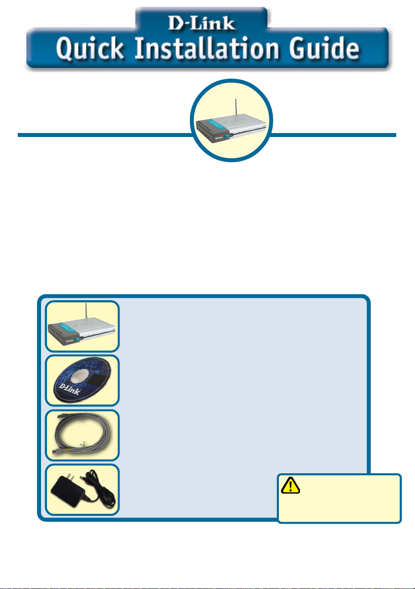
Check Your Package Contents
DI-824VUP+ 2.4GHz Wireless VPN Router
and Print Server
CD-ROM (containing Manual and Warranty)
Ethernet (CAT5 UTP/Straight-Through)
Cable
5V DC Power Adapter
If any of the above items are missing, please contact your reseller.
©2003 D-Link Systems, Inc. All rights reserved. Trademarks or registered trademarks are the property of their respective holders. Software and
specifications subject to change without notice. DI-824VUP+. 11072003
1
Using a power supply
with a different voltage
rating will damage and void
the warranty of this product.
Page 2
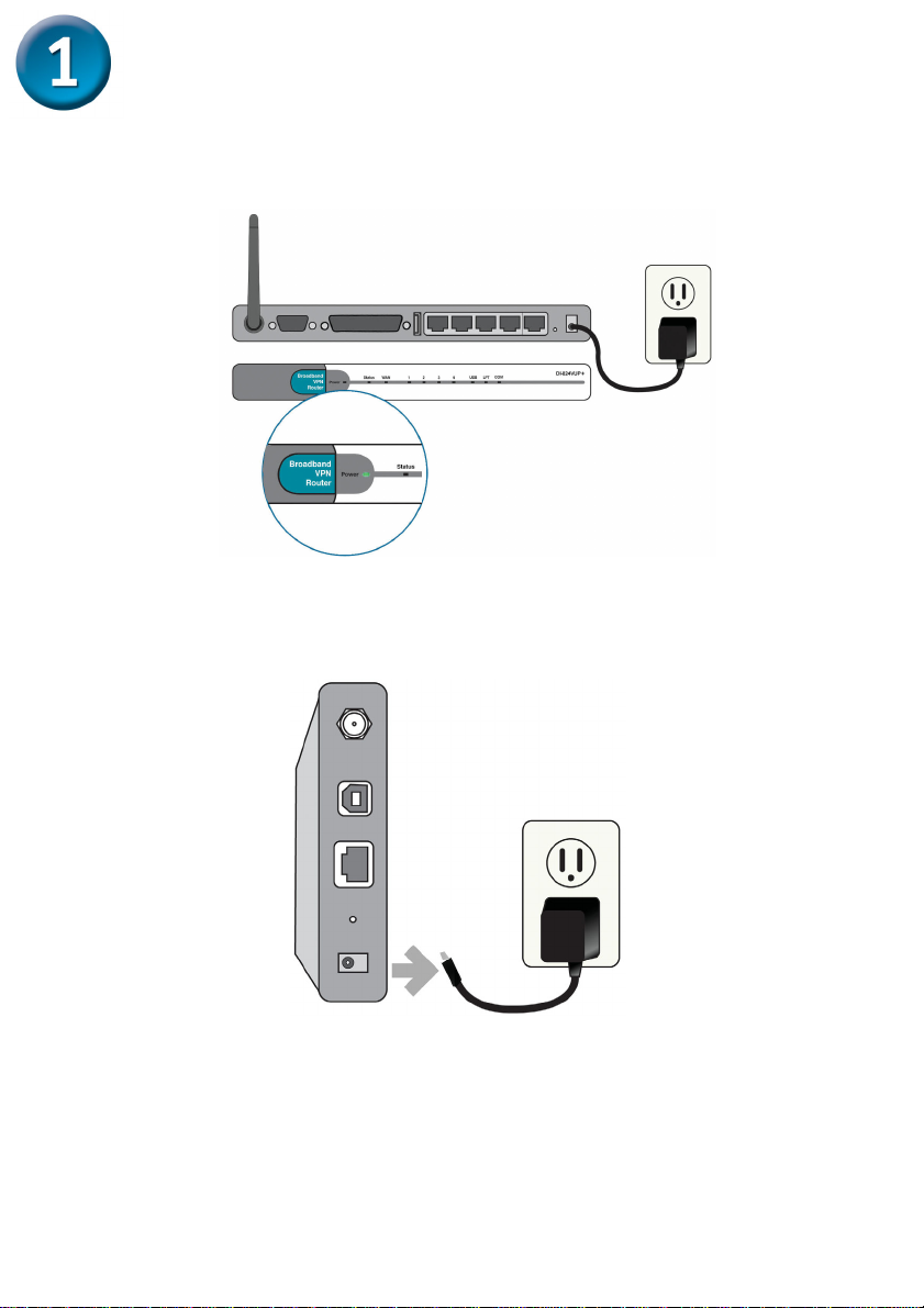
Connecting The DI-824VUP+ 2.4GHz Wireless VPN Router To Your Network
A. First, connect the power adapter to the receptor at the back panel of the
DI-824VUP+ and then plug the other end of the power adapter to a wall outlet or
power strip. The Power LED lights up indicating proper operation. (Fig. A)
(Fig. A)
B. 1. Power off your Cable or DSL modem; the devices that do not have a on/off
switch and will require you to unplug the power adapter. Now, the DI-824VUP+
should be powered on and the Cable / DSL modem should be turned off.
Cable / DSL modem (Power Off) – DI-824VUP+ (Power On) (Fig.B)
(Fig. B)
2.Connect an Ethernet cable to the Ethernet jack located on the Cable / DSL
modem. After the Ethernet cable is securely connected, power on the Cable / DSL
modem by turning on the unit or plugging in the power adapter.
Cable / DSL modem (Power On) – DI-824VUP+ (Power On)
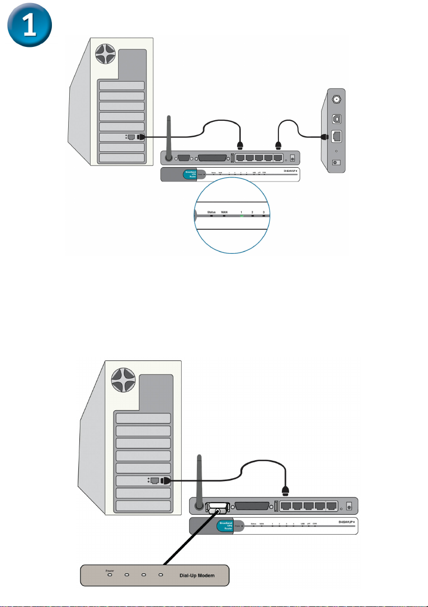
3. Insert the other end of the Ethernet cable to the WAN PORT on the back panel
of the DI-824VUP+. The WAN LED light will illuminate to indicate proper
connection. If the WAN LED is not illuminated, please go back to step B1 and
repeat the steps. (Fig.C)
2
Page 3
Continued...
(Fig. C)
C. Insert an Ethernet cable to LAN Port 1 on the back panel of the DI-824VUP+ and
an available Ethernet port on the network adapter in the computer you are using to
configure the DI-824VUP+. The LED light for LAN Port 1 illuminates to indicate
proper connection. (Note: The LAN Ports on the DI-824VUP+ are Auto-MDI/MDIX.
Meaning you can use a straight-through or crossover-Ethernet cable in the LAN
Ports.) (Fig.C)
D. COM Port for dial-up Internet connection (optional). (Fig.D)
(Fig. D)
3
Page 4
Continued...
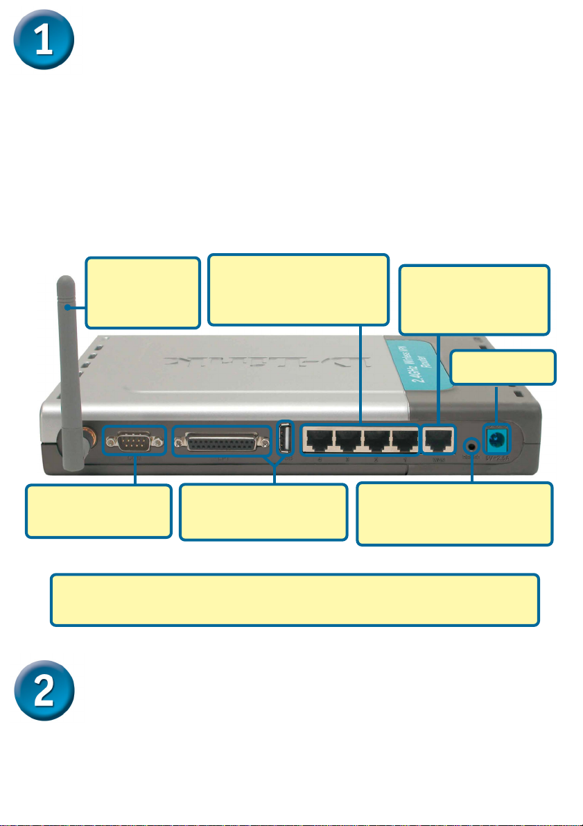
E. Computers equipped with 802.11g wireless adapters will be able to connect to the
DI-824VUP+. The DWL-G650+ Wireless Cardbus Adapter and the DWL-G520+
Wireless PCI Adapter will be able to connect out of the box with the router using
their default wireless settings.
F. Connect your Parrallel or USB printer here.
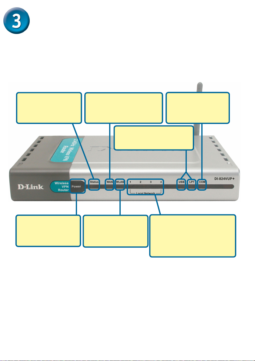
E. Antenna Used
to wirelessly
connect to
802.11g adapters.
D. COM Port Used to
connect to an external
dial-up modem.
C. LAN PORTS These are the
connections for Ethernet
cables to Ethernet enabled
computers.
F. Parallel and USB Printer
Port Used to connect to a
Printer.
B. WAN PORT This is for
the connection of an
Ethernet cable to the
Cable or DSL modem.
A. Receptor for
Power Adapter.
Reset Button
Pressing this button restores
the Router to its original factory
default settings.
The LAN Ports on the DI-824VUP+ are Auto MDI/MDIX. Meaning you can
use a straight-through or crossover Ethernet cable in the LAN Ports.)
Restart Your Computer
4
Page 5
Connecting Additional Computers To The
DI-824VUP+ 2.4GHz Wireless VPN Router
Using additional Ethernet (CAT5 UTP) cables, connect your Ethernet-equipped
computers to the remaining Ethernet LAN ports on the back panel of the DI-824VUP+.
Status LED – a steady
blinking light indicates
that the unit is working
properly.
POWER LED – a solid
light indicates a proper
connection to the
power supply.
WAN LED – a blinking light
indicates connection on the
WAN port. This LED blinks
during data transmission.
USB and LPT LEDs – a
solid light indicates a proper
connection to a Printer.
WLAN LED – will flash
consistently to indicate
that the DI-824VUP+ is
working properly.
LOCAL NETWORK LEDs – a
solid light on the port indicates
a connection to an Ethernet
enabled computer on ports 1-4.
This LED blinks during data
transmission.
COM LED – a solid
light indicates a proper
connection to a dial-up
modem.
5
Page 6
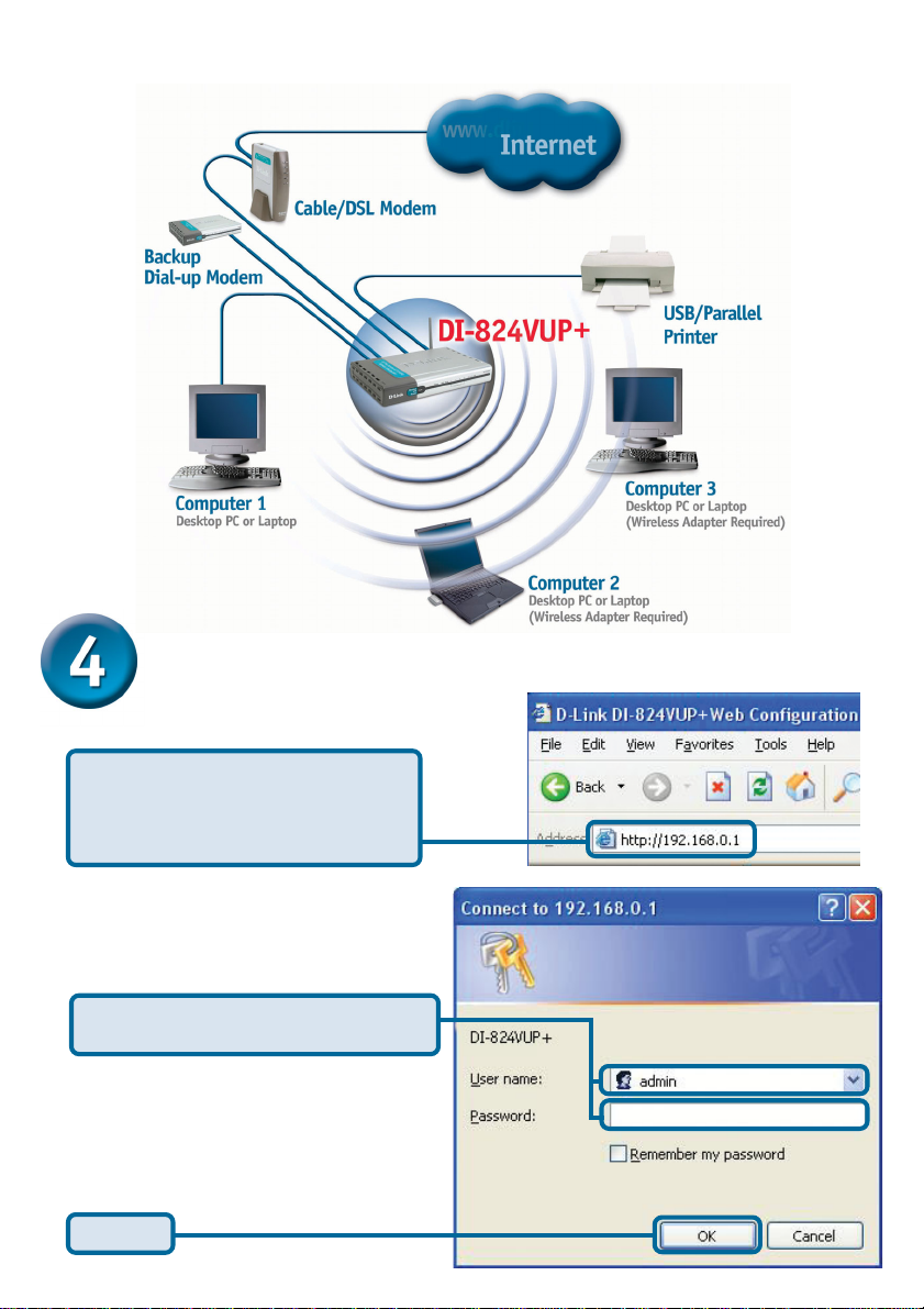
When you have completed the steps in this Quick Installation
Guide, your connected network should look similar to this:
Using The Setup Wizard
Open your Web browser and
type “http://192.168.0.1” into the
URL address box. Then press the
Enter or Return key.
The logon pop-up screen will appear.
Type “admin” for the username and
leave the password field blank.
Click OK
6
Page 7

The Setup Wizard (continued)
Once you have logged in, the
Home screen will appear.
Click Run Wizard
You will see the following screens.
Click Next
Set up your new password.
You have the option to establish a
password.
Click Next
7
Page 8

The Setup Wizard (continued)
Choose your time zone from the drop
down list.
Click Next
A this point, the setup wizard will try to
auto-detect your Internet connection
type. If you have a Dynamic or PPPoE
connection, you will be brought to the
corresponding page.
Select your Internet Connection.
You will be prompted to select the type of
Internet connection for your router.
If you are unsure of which
setting to select, please contact
your Internet Service Provider.
Click Next
8
Page 9

The Setup Wizard (continued)
If you selected Dynamic IP Address,
this screen will appear: (Used mainly
for Cable Internet service.)
Click the “ Clone MAC Address”
button to automatically copy the
MAC address of the network
adapter in your computer. You can
also manually type in the MAC
address.
This setup should be done on the computer
that is registered on the ISP’s network.
Click Next
Please continue to Wireless Setup.
If your ISP requires a Static IP
Address, and this option is selected,
then this screen will appear:
Enter the IP address information
originally provided to you by your ISP.
You will need to complete all the
required fields.
Click Next
Please continue to Wireless Setup.
9
Page 10

The Setup Wizard (continued)
If your ISP uses PPPoE (Point-toPoint Protocol over Ethernet), and
this option is selected, then this
screen will appear: (Used mainly for
DSL Internet service.)
Please be sure to remove
any existing PPPoE client
software installed on your
computers.
Enter in the username and password provided to you by your ISP.
Click Next
Wireless Setup
The default wireless settings for
your 802.11g wireless network are:
SSID = default
Channel = 6
You can change these settings to
match an existing wireless network.
If you wish to use encryption for your
802.11g network, the DI-824VUP+ is
capable of three levels of wireless
encryption - 64-bit, 128-bit, and 256bit. By default the encryption is
disabled. You can change the
encryption settings for more secure
wireless communication.
Click Next
10
Page 11

Your Setup is Complete!
Click Restart
Test Internet Connection
You will be returned to the Home tab.
Click to Exit
Then relaunch your Web
browser (i.e., Internet
Explorer or Netscape
Navigator), to link to your
favorite Web site to test
your Internet connection.
For additional settings or
information, refer to the
Advanced, Tools, or
Status tabs on the web-
management interface; or
to the Manual located on
the CD.
11
Page 12

APPENDIX
Installing the Print Server Software
Insert the installation CD-ROM into the CDROM drive. The following window will be
shown automatically. If it is not, please run
“autorun.exe” on the CD-ROM.
Click Install Print Sever
Software
Select your Windows
operating system
Wait until the following Welcome dialog
appears.
Click Next
Select the destination folder.
Click Next
12
Page 13

Installing the Print Server Software (continued)
Then, the setup program will begin to install
the programs into the destination folder.
When the following window is displayed.
Click Finish
Click OK
After rebooting your computer, the software installation procedure is finished.
Configuring on Windows 98se/Me Platforms
After you finish the software installation
procedure, your computer will be capable of
network printing provided by the DI-824VUP+.
For convenience, we call the printer connected to the printer port of the DI-824VUP+ a
printer server. On a Windows 95/98 platform,
open the Printers window in the My Com-
puter menu.
Now, you can configure the print server of the
DI-824VUP+:
Find out the corresponding icon of your printer
server, for example, the HP LaserJet 6L.
Right click on that icon, and then select
Properties.
The following screen appears:
13
Page 14

Configuring on Windows 98se/Me Platforms (continued)
Click on the
Details tab
Choose the “PRTmate: (All-in-1)” from the
list attached at the Print To item. Be sure
that the Printer Driver item is configured to
the correct driver of your printer server.
Click Port Settings
Choose your printer interface.
Type in the IP address of the DI-824VUP+.
Click OK
Configuring on Windows 2000/XP Platforms
Click Port
The configuration procedure for a Windows
2000/XP platform is similar to that of
Windows 95/98 except the screen of printer
Properties:
Click Configure Port
Choose your printer interface.
Type in the IP address of the DI-824VUP+.
Click OK
(Note: Screen shots are taken in Windows 2000,
similar screens will appear in Windows XP.)
14
Page 15

APPENDIX (continued)
To connect to the network, make sure the network adapter in your computer is
configured properly. Here’s how to configure the network adapter to obtain an IP
address automatically for the DI-824VUP+ Broadband Router.
For Microsoft Windows XP: Go to Start >
right click on My Network Places > select
Properties > Right click on the Network
Connection associated with the Ethernet
adapter and select Properties (i.e., D-Link
DFE-530TX+).
Click Internet Protocol (TCP/IP)
Click Properties
Select Obtain an IP address
automatically
Click OK
Restart your computer
15
Page 16

For Apple Macintosh OS X:
Go to the Apple Menu Click on System
Preferences and Select Network
Select Built-in Ethernet
in the show pull down
menu
Select Using DHCP in
the Configure pull down
menu
Click on
Network
Click on Apply Now
The IP address information,
the Subnet Mask, the Router’s
IP address and the Ethernet
adapter address will appear
16
Page 17

17
Page 18

Technical SupportTechnical Support
Technical Support
Technical SupportTechnical Support
You can find software updates and user documentation on the D-Link website.
D-Link provides free technical support for customers within the United States and
within Canada for the duration of the warranty period on this product.
U.S. and Canadian customers can contact D-Link technical support through our
website, or by phone.
Tech Support for customers within the United States:
D-Link Technical Support over the Telephone:
(877) 453-5465
24 hours a day, seven days a week.
D-Link Technical Support over the Internet:
http://support.dlink.com
email:support@dlink.com
Tech Support for customers within Canada:
D-Link Technical Support over the Telephone:
(800) 361-5265
Monday to Friday 8:30am to 9:00pm EST
D-Link Technical Support over the Internet:
http://support.dlink.ca
email:support@dlink.ca
18
 Loading...