

Page 1

D-Link
DI-713
User’s Manual
Page 2

Table of Contents
Chapter 1 Introduction.................................................................................1
1.1 Functions and Features...................................................................1
1.2 Packing List ....................................................................................2
Chapter 2 Hardware Installation..................................................................3
2.1 Panel Layout ...................................................................................3
2.2 Procedure for Hardware Installation...............................................5
Chapter 3 Network Settings .........................................................................8
3.1 Make Correct Network Settings to the Computer ..........................8
Chapter 4 Configuring the DI-713...............................................................9
4.1 Start-up and Log in .........................................................................9
4.2 Status.............................................................................................10
4.4 Primary Setup ...............................................................................12
4.5 DHCP Server ................................................................................14
4.6 Virtual Server................................................................................15
4.7 Special AP ....................................................................................16
4.8 Access Control..............................................................................17
4.9 Misc Items ....................................................................................18
4.10 Wireless Setting ..........................................................................19
Appendix A TCP/IP Configuration for Windows 95/98 ...........................20
A.1 Install TCP/IP Protocol into Your PC..........................................20
A.2 Set TCP/IP Protocol for Working with the DI-713 .....................21
Technical Support.......................................................................................29
Warranty.....................................................................................................30
Registration.................................................................................................39
REV: 030205 i
Page 3

Chapter 1 Introduction
Congratulations on your purchase of DI-713 Wireless Broadband Router. The DI-713 is
specifically designed for Small Office and Home Office needs. It provides a complete
solution for Internet surfing, and it is easy to configure and operate for even non-technical
users. Instructions for installing and configuring the DI-713 can be found in this manual.
Before you install and use the DI-713, please read this manual carefully to fully
understand the functions of the DI-713.
1.1 Functions and Features
High speed Wireless LAN connection
11Mbps data rate by incorporating Direct Sequence Spread Spectrum (DSSS).
Roaming
Provides seamless roaming within the IEEE 802.11b WLAN infrastructure.
IEEE 802.11b* compatible
Allowing inter-operation among multiple vendors.
Auto fallback
11M, 5M, 2M, 1M data rate with auto fallback.
Broadband modem and IP sharing
Connects multiple computers to a broadband (Cable or DSL) modem or an
Ethernet router to share the Internet connection.
Auto-sensing Ethernet Switch
Equipped with a 3-port 10/100 auto-sensing Ethernet switch.
VPN supported
Supports multiple PPTP sessions and allows setup of a VPN server and VPN
clients.
Firewall
All unwanted packets from outside intruders are blocked to protect your
Intranet.
DHCP server supported
All of the networked computers can retrieve TCP/IP settings automatically from
the DI-713.
Web- based configuring
Configurable through any networked computer’ s web browser using Netscape
or Internet Explorer.
Access Control supported
Allows you to assign different access rights for different users.
Virtual Server supported
Enables you to expose WWW, FTP and other services on your LAN to be
accessible to Internet users outside of you LAN.
User-Definable Application Sensing Tunnel
User can define the attributes to support the special applications requiring
REV: 101404
1
Page 4

multiple connections, like Internet gaming, video conferencing, Internet
telephony and so on, then the DI-713 can sense the application type and open a
multi-port tunnel for it.
DMZ Host supported
Lets a networked computer to be fully exposed to the Internet; this function is
used when the special application sensing tunnel feature is insufficient to allow
an application to function correctly.
1.2 Packing List
One DI-713 wireless broadband router unit
One power adapter
Two CAT-5 UTP Straight-through Fast Ethernet cable
One CD with HTML Quick Installation Guide and PDF User’ s Manual
One Quick Installation Guide
REV: 101404
2
Page 5
Chapter 2 Hardware Installation
2.1 Panel Layout
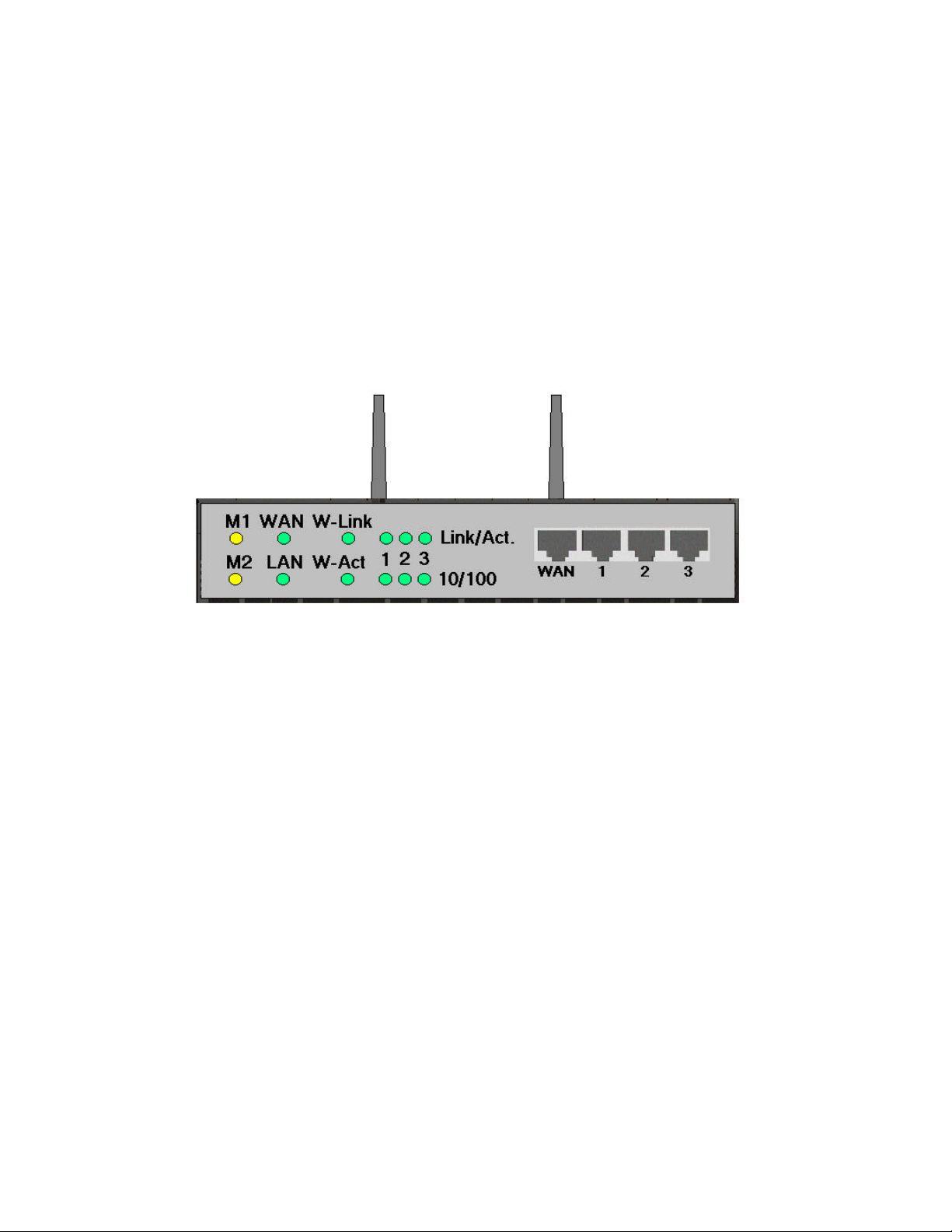
2.1.1. Front Panel
The front panel features three 10/100 Mbps Ethernet ports, one Wide Area network
(WAN) port and diagnostic LED indicators. The WAN port connects your DSL or cable
modem to the router. The LAN ports are used to connect to your computers or other
network devices. LEDs monitor the status of each port.
Figure 2-1 Front Panel
Port:
WAN: the port where you will connect your Cable or DSL modem or Ethernet router.
Port 1-3: the ports where you will connect networked computers and other devices.
REV: 101404
3
Page 6

LED:
LED Function Color Status Description
M1 System status 1 Orange Blinking
On
M2 System status 2 Orange
Blinking
WAN
LAN
W-Link
W-Act Wireless activity Green Blinking
Link/Act.
1~3
10/100
1~3
WAN port
activity
LAN port
activity
Backbone
activity
Link status Green
Data Rate Green On
Green
Green
Green Blinking
On The WAN port is linked
Blinking
On The LAN port is linked
Blinking
On
Blinking
The DI-713 is functioning
properly
The DI-713 is working for some
service
The DI-713 is being configured
or upgraded. Don’ t turn it off !
The WAN port is sending or
receiving data
The LAN port is sending or
receiving data
Sending or receiving data from
wireless to wired backbone
Sending or receiving data via
wireless
An active station is connected to
the corresponding LAN port.
The corresponding LAN port is
sending or receiving data
Data is transmitting in 100Mbps
on the corresponding LAN port.
REV: 101404
4
Page 7
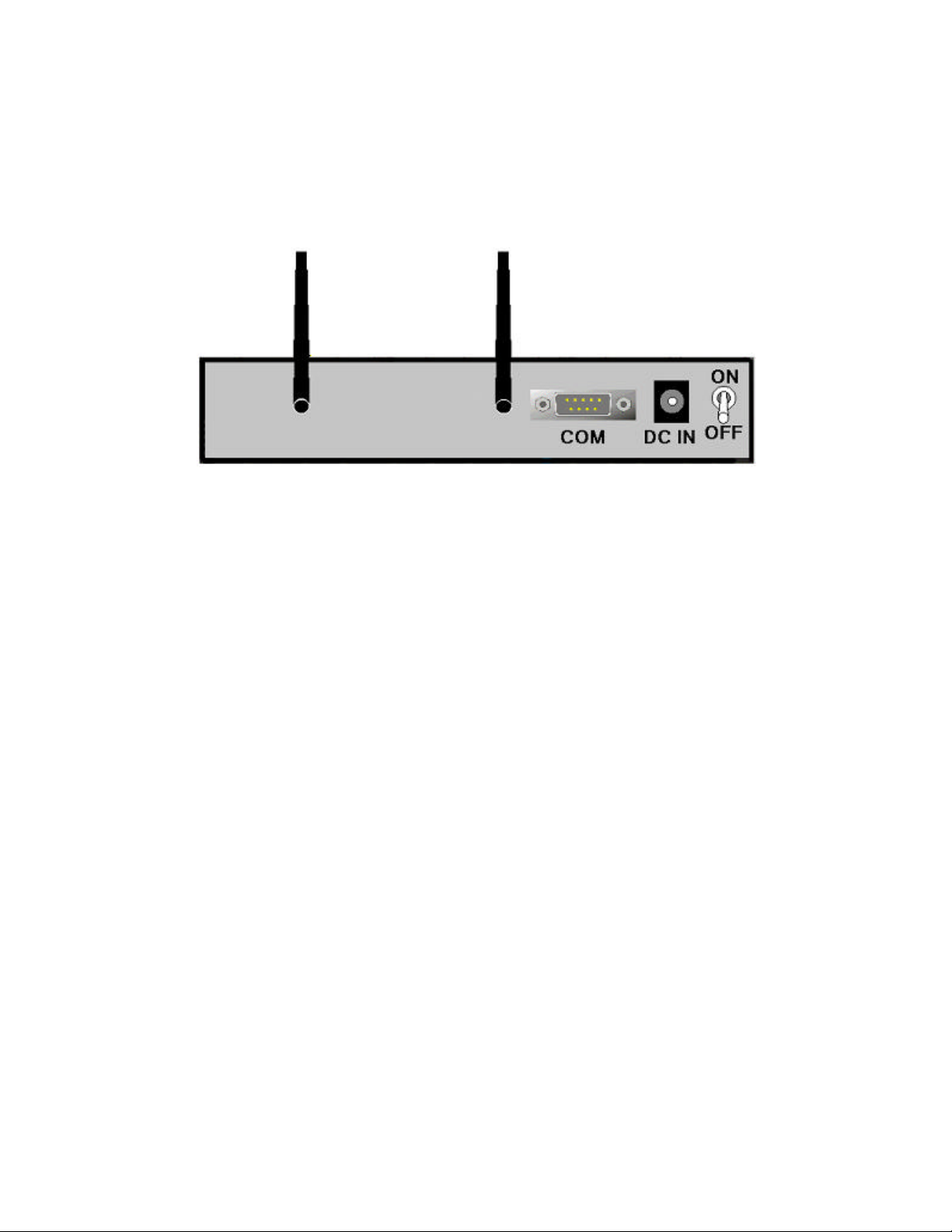
2.1.2. Rear Panel
Figure 2-2 Rear Panel
Ports:
Port Description
ON/OFF Power switch
DC IN Power inlet (DC 5V)
COM Serial port (connect analog modem or console cable)
2.2 Procedure for Hardware Installation
1. Decide where to place your Wireless Broadband Router:
You can place your Wireless Broadband Router on a desk or other secure surface, or
you can mount it on a wall. For optimal performance, place your Wireless Broadband
Router in the center of your office (or your home) in a location that is away from any
potential source of interference, such as a metal wall or microwave oven. This
location must be close to power and a network connection.
REV: 101404
5
Page 8
2. Setup LAN connection:
a. Wired LAN connection: connect an Ethernet cable from your computer’s Ethernet
port to one of the LAN ports of the DI-713.
b. Wireless LAN connection: make sure the antennas are in a vertical position (if not,
rotate over 90 degrees).
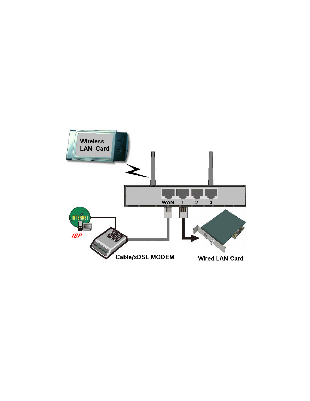
3. Setup WAN connection: prepare an Ethernet cable for connecting the DI-713 to your
cable/xDSL modem or Ethernet backbone. Figure 2-3 illustrates the WAN
connection.
REV: 101404
Figure 2-3 Setup of LAN and WAN connections for the DI-713.
6
Page 9

4. Power on:
Connect the power cord to a power outlet and turn the power switch to the on
position; the DI-713 will automatically enter the self-test phase. When it is in the selftest phase, the indicators M1 and M2 will be lit for about 10 seconds, and then M1
and M2 will flash 3 times to indicate that the self-test operation has finished. Finally,
the M1 will continuously flash once per second to indicate that the DI-713 is in
normal operation.
REV: 101404
7
Page 10

Chapter 3 Network Settings
To use the DI-713 correctly, you must properly configure the network settings of your
computers.
3.1 Make Correct Network Settings to the Computer
The default IP address of the DI-713 is 192.168.0.1, and the default subnet mask is
255.255.255.0. These addresses can be changed to meet your need, but the default values
are used in this manual. If the TCP/IP environment of your computer has not yet been
configured, you can refer to Appendix B to configure it. For example,
1. configure IP as 192.168.0.5, subnet mask as 255.255.255.0 and gateway as
192.168.0.1, or,
2. configure your computers to load TCP/IP setting automatically, that is, via DHCP
server built into the DI-713.
After installing the TCP/IP communication protocol, you can use the ping command to
check if your computer has successfully connected to the DI-713. The following example
shows the ping procedure for Windows 95 platforms. First, execute the ping command
from a DOS window
ping 192.168.0.1
If the following messages appear:
Pinging 192.168.0.1 with 32 bytes of data:
Reply from 192.168.0.1: bytes=32 time=2ms TTL=64
a communication link between your computer and the DI-713 has been successfully
established. Otherwise, if you get the following messages,
Pinging 192.168.0.1 with 32 bytes of data:
Request timed out.
there must be something wrong with the installation. Follow the steps again to make sure
the network settings are correct. You should check the following items in sequence.
1. Is the Ethernet cable correctly connected between the DI-713 and your computer?
Tip: The LAN LED of the DI-713 and the link LED of network card on your
computer must be lit.
2. Is the TCP/IP environment of your computers properly configured?
Tip: If the IP address of the DI-713 is 192.168.0.1, the IP address of your computer
must be 192.168.0.X and default gateway must be 192.168.0.1.
REV: 101404
8
Page 11
Chapter 4 Configuring the DI-713
The DI-713 provides a Web based configuration scheme, that is, configuring by Netscape
Communicator or Internet Explorer. This approach can be adopted in any MS Windows,
Macintosh or UNIX based platforms a Java compliant browser.
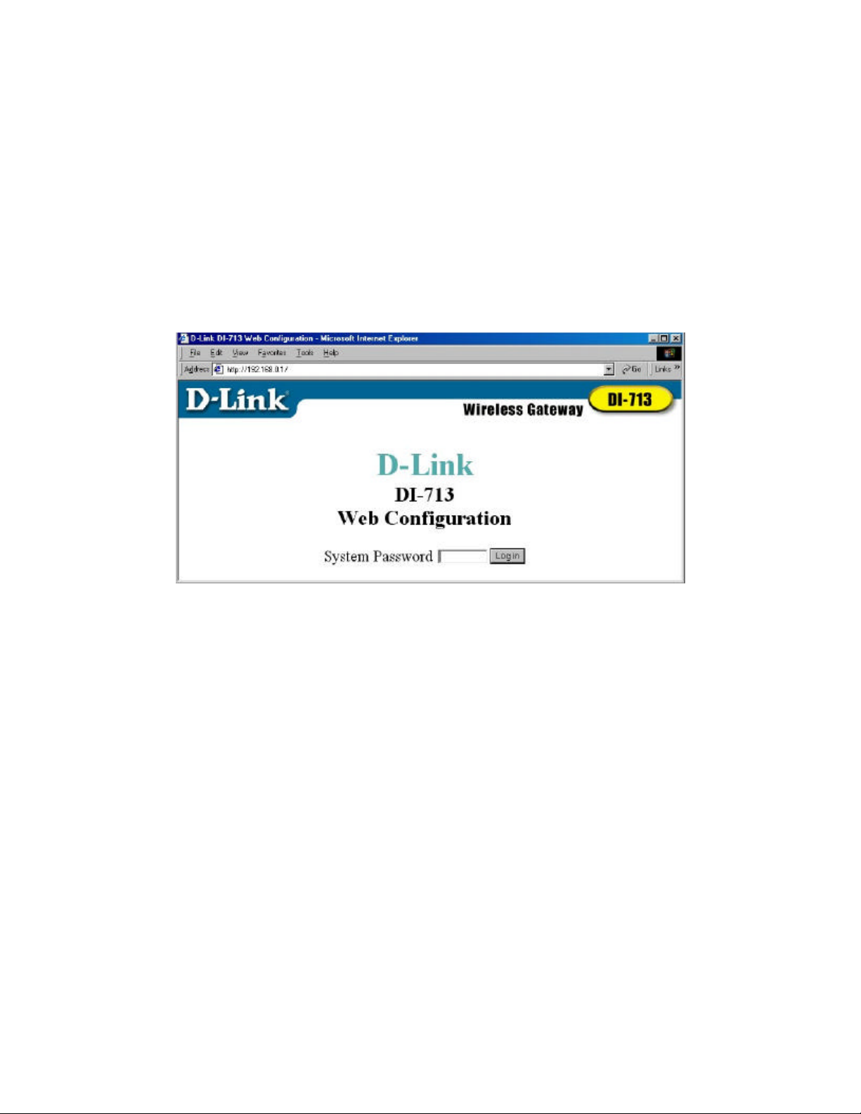
4.1 Start-up and Log in
Activate your browser. Then, type the DI-713’ s IP address in the Location (for Netscape)
or Address (for IE) field and press ENTER. For example: http://192.168.0.1.
After the connection is established, you will see the web user interface of the DI-713.
There are two appearances of web user interface: for general users and for system
administrator.
To log in as an administrator, enter the system password (the factory setting is ”admin”) in
the System Password field and click on the Log in button. If the password is correct, the
web appearance will be changed into administrator configure mode. As listed in its main
menu, there are several options for system administration.
REV: 101404
9
Page 12
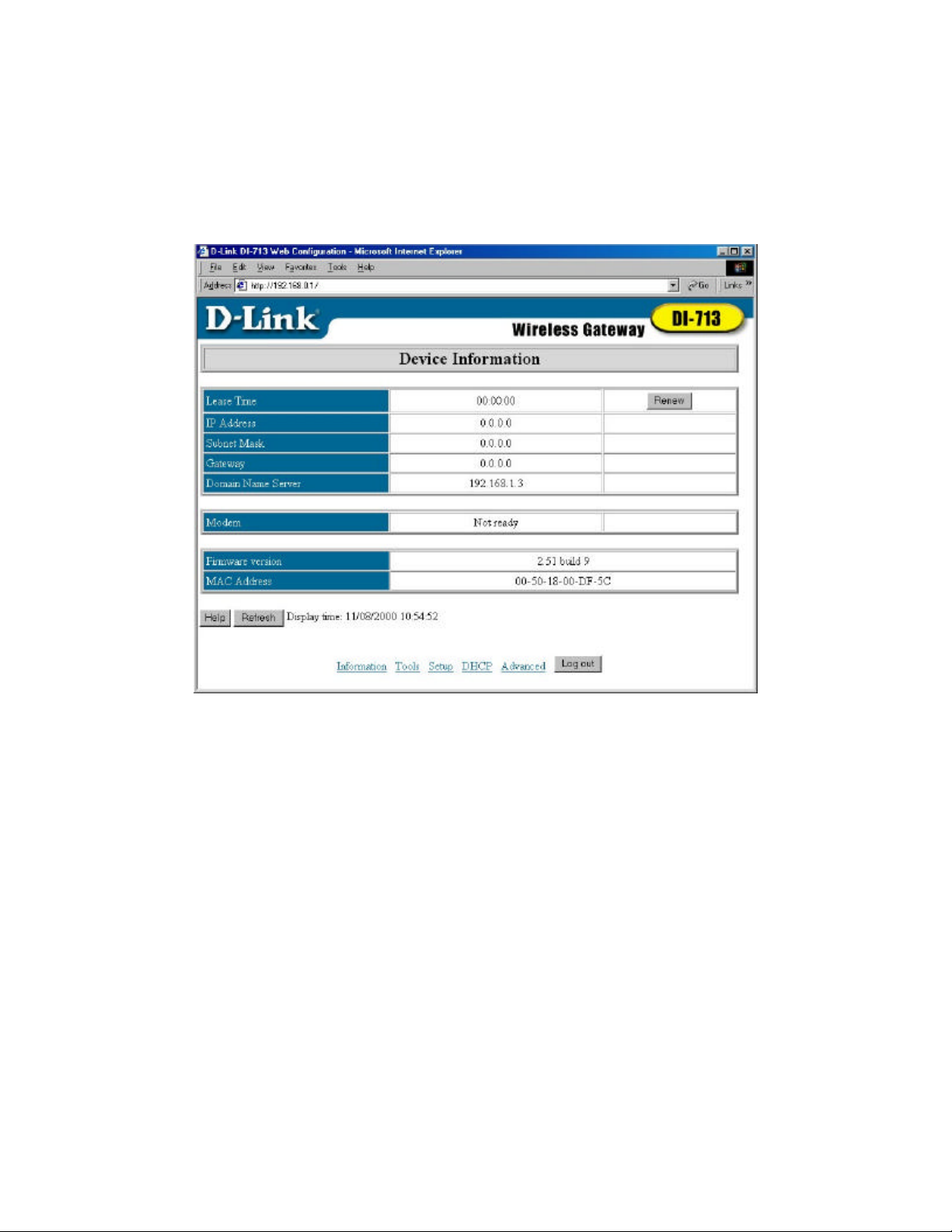
4.2 Status
This option provides observation of the DI-713’ s configuration status. If the WAN port is
assigned a dynamic IP address, a “Renew” or “ Release” button may appear. You can click
this button to manually renew or release the IP. This screen also provides the Firmware
Version and MAC Address information. Pressing the Refresh button will update the
Device Information screen to show the current status.
REV: 101404
10
Page 13
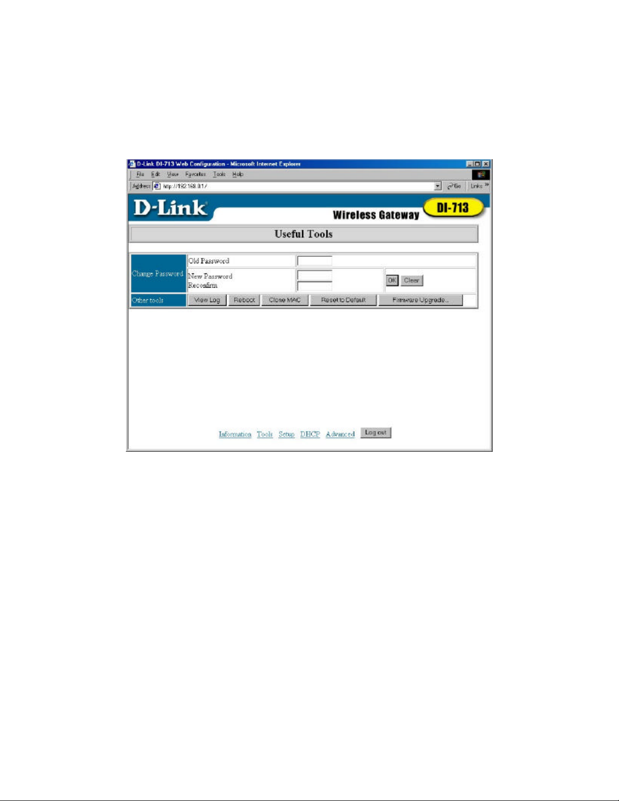
4.3 Toolbox
This option enables you to change the administrator password, view log information,
reboot the DI-713, clone the MAC Address, reset to default settings, and perform a
firmware upgrade.
Note: we strongly recommend you to change the system password for security reasons. If
you forgot the system password, please refer to Appendix A to reset a new one.
REV: 101404
11
Page 14

4.4 Primary Setup
This option is crucial to enable the DI-713 to work properly. The setting items and the
web appearance will change depending on the WAN type you choose. Choose the correct
WAN type before you start.
1. LAN IP Address: the DI-713’s IP address. The default address is 192.168.0.1. You
can change it to meet your need.
2. WAN Type: WAN connection type of your ISP. You can click the Change button to
choose the correct setting from the following four options:
A. Static IP Address: your ISP assigns you an IP address.
B. Dynamic IP Address: Obtain an IP address from your ISP automatically.
C. PPP over Ethernet: Some ISPs require the use of PPPoE to connect to their
services. This requires a Username and Password provided by the ISP.
D. Dial-up Network : Connection to the Internet via PSTN/ISDN modem.
REV: 101404
12
Page 15

4.4.1 Static IP Address
Enter the proper WAN IP Address, Subnet Mask, Gateway, Primary and Secondary DNS
settings provided by your ISP. Contact your ISP if you do not have this information.
4.4.2 Dynamic IP Address
1. Host Name: optional. Required by some ISPs, for example, @Home.
2. Renew IP Forever: this feature enables the DI-713 to renew its IP address
automatically when the lease time is being expired even if the system is idle.
4.4.3 PPP over Ethernet
1. PPPoE Account and Password : the account and password your ISP assigned to you.
If you don't want to change the password, keep it empty.
2. PPPoE Service Name: optional. Input the service name if your ISP requires it.
3. Maximum Idle Time: the maximum time the connection is idle before you are
disconnected from your ISP and your PPPOE session is terminated.
4.4.4 Dial-up Network
1. Dial-up Telephone, Account and Password : assigned by your ISP. If you don't want
to change the password, keep it empty.
2. Primary and Secondary DNS: automatically assigned if they are configured as
"0.0.0.0."
3. Maximum Idle Time: the time of no activity to disconnect your dial-up session.
4. Baud Rate: the communication speed between the DI-713 and your MODEM or
ISDN TA.
5. Extra Setting: needed to optimize the communication quality between the ISP and
your MODEM or ISDN TA
REV: 101404
13
Page 16

4.5 DHCP Server
The settings of a TCP/IP environment include Host IP, Subnet Mask, Gateway, and DNS
configurations. It is not a simple task to correctly configure all the computers in your LAN
environment. Fortunately, DHCP provides a rather simple approach to handle all these
settings. The DI-713 supports the function of a DHCP server, which is set as default. The
DHCP server is able to configure of your computers to “automatic receive IP settings”
mode, then when your computer is powered on, it will automatically load the proper
TCP/IP settings from the DI-713. The settings of DHCP server options include the
following items:
1. DHCP Server : Choose “ Disable” or “Enable.”
2. Range of IP Address Pool: Whenever there is a request, the DHCP server will
automatically allocate an unused IP address from the IP address pool to the
requesting computer. You must specify the starting and ending address of the IP
address pool.
3. Domain Name: Optional, this information will be passed to the client.
REV: 101404
14
Page 17

4.6 Virtual Server
The DI-713’s NAT firewall filters out unrecognized packets to protect your Intranet, so all
hosts behind the DI-713 are invisible to the outside world. If you wish, you can make
some of them accessible by enabling the Virtual Server Mapping.
A virtual server is defined as a Service Port, and all requests to this port will be redirected
to the computer specified by the Server IP.
For example, if you have an FTP server (port 21) at 192.168.0.5, a Web server (port 80) at
192.168.0.7, and a VPN server at 192.168.123.10, then you need to specify the following
virtual server mapping table:
Service Port Server IP Enable
21 192.168.0.5 V
80 192.168.0.7 V
1723 192.168.0.10 V
REV: 101404
15
Page 18

4.7 Special AP
Some applications require multiple connections, like Internet games, Video conferencing,
Internet telephony and so on. Due to the firewall function, these applications cannot work
with a pure NAT router. The Special Applications options allow some of these
applications to work with a NAT router. If Special Applications is still insufficient to
allow an application to function correctly, try DMZ host in the Misc Items options.
1. Trigger: the outbound port number the application issued first.
2. Incoming Ports: when the trigger packet is detected, the inbound packets to the
specified port numbers are allowed to pass the firewall.
The DI-713 provides some predefined settings in the gray pad on the bottom of the web
page. Choose the Popular application and click Copy t o copy the predefined setting.
Note! At any time, only one PC can use each Special Application tunnel.
REV: 101404
16
Page 19

4.8 Access Control
Access Control allows you to assign different access rights for different users. First, you
have to divide users into different groups. Users are identified by their IP addresses. You
can assign the members of Group 1, 2 and 3. The others are all members of the Default
Group. Second, you have to assign the access rights of each group. Access rights can
allow or block users to access specified TCP and UDP ports. For example: If you want IP
addresses 50-99 to block access to port 21 and 119, you would insert 50-99 into the Group
1 members box. Change the Ports drop-down box to Block, and type 21,119 into the box
to the right of the Block box.
Group Members Access Right Comments
Default - Allow () No access rights (allow nothing)
Group 1 50-99 Allow (25,53)
Group 2 100-199 Block (21,119)
Group 3 1-9,20 Block () Fully access (block nothing)
Can browse(80), receive(110) and
send(25) email only
Cannot read net news(119) and
FTP(21) only
REV: 101404
17
Page 20

4.9 Misc Items
1. IP Address of DMZ Host: DMZ (DeMilitarized Zone) Host is a host without the
protection of firewall. It allows a computer to be exposed to unrestricted 2-way
communication. Note that, this feature should be used only when needed.
2. Remote Administrator Host: In general, only Intranet user can browse the built-in
web pages to perform administration tasks. This feature enables you to perform
administration tasks from a remote host. If this feature is enabled, only the specified
IP address can perform remote administration. If the specified IP address is 0.0.0.0,
any host can connect to the DI-713 to perform administration task. When this feature
is enabled, the web port will be shifted to 88.
REV: 101404
18
Page 21

4.10 Wireless Setting
Wireless settings allow you to set the wireless configuration items.
1. Network ID (SSID): Network ID is used for identifying the WLAN. Client stations
can roam freely over the DI-713 and other Access Points that have the same Network
ID. (The factory setting is “ default”)
2. Channel: The radio channel number. The permissible channels depend on the
Regulatory Domain. (The factory setting is channel 6)
3. Security: Select the data privacy algorithm you want. Enabling the security can
protect your data while it is transferred from one station to another. The standardized
IEEE 802.11 WEP (based on a 40 bit shared key) is used here. When you enable the
security, please input 10 hex-decimal digits (40 bits) in the text box.
REV: 101404
19
Page 22

Appendix A TCP/IP Configuration for Windows 95/98
This section is an introduction on you how to install the TCP/IP protocol into your
personal computer if the TCP/IP protocol hasn’ t been installed yet. Under the normal
installation procedure for network adapters, the TCP/IP protocol will be installed
automatically. We are assuming that you have successfully installed one network card or
wireless adapter on your personal computer. If not, please refer to your network card
manual. Moreover, the Section A.2 tells you how to set TCP/IP values for working with
the DI-713 correctly.
A.1 Install TCP/IP Protocol into Your PC
1. Click the Start button and choose Settings, then click Control Panel.
2. Double click the Network icon and select the Configuration tab in the Network
window.
3. Click the Add button to add a network component to your PC.
4. Double click the Protocol to add TCP/IP protocol.
REV: 101404
20
Page 23

5. Select the Microsoft item in the manufactures list. And choose TCP/IP in the
Network Protocols. Click the OK button to return to the Network window.
6. The TCP/IP protocol will be listed in the Network window. Click OK to complete the
install procedure and restart your PC to enable the TCP/IP protocol.
A.2 Set TCP/IP Protocol for Working with the DI-713
1. Click the Start button and choose Settings, then click Control Panel.
REV: 101404
21
Page 24

2. Double click the Network icon. Select the TCP/IP line that has been associated to
your network card in the Configuration tab of the Network window.
3. Click the Properties button to set the TCP/IP protocol for the DI-713.
4. You have two setting methods to choose from:
A. Get IP via DHCP server, or
REV: 101404
22
Page 25

a. Select Obtain an IP address automatically in the IP Address tab.
REV: 101404
23
Page 26

b. Make sure no settings are set in the Gateway tab.
REV: 101404
24
Page 27

c. Choose Disable DNS in the DNS Configuration tab.
REV: 101404
25
Page 28

B. Configure IP manually
a. Select Specify an IP address in the IP Address tab. The default IP address
of the DI-713 is 192.168.0.1. So please use 192.168.0.xxx (xxx is
between 2 and 254) for IP Address field and 255.255.255.0 for Subnet
Mask field.
REV: 101404
26
Page 29

b. In the Gateway tab, add the IP address of the DI-713 (default IP is
192.168.0.1) in the New gateway field and click Add button.
REV: 101404
27
Page 30

c. In the DNS Configuration tab, add the DNS values which are provided by
the ISP into DNS Server Search Order field and click Add button.
REV: 101404
28
Page 31

Technical Support
You can find software updates and user documentation on the D-Link website.
D-Link provides free technical support for customers within the United States and
within Canada for the duration of the warranty period on this product.
U.S. and Canadian customers can contact D-Link technical support through our web
site, or by phone.
Tech Support for customers within the United States:
D-Link Technical Support over the Telephone:
(877) 453-5465
24 hours a day, seven days a week.
D-Link Technical Support over the Internet:
http://support.dlink.com
email:support@dlink.com
Tech Support for customers within Canada:
D-Link Technical Support over the Telephone:
(800) 361-5265
Monday to Friday 7:30am to 12:00am EST
D-Link Technical Support over the Internet:
http://support.dlink.ca
email:support@dlink.ca
When contacting technical support, please provide the following information:
• Serial number of the unit
• Model number or product name
• Software type and version number
Page 32

Warranty
(All countries and regions excluding USA)
Wichtige Sicherheitshinweise
1. Bitte lesen Sie sich diese Hinweise sorgfältig durch.
2. Heben Sie diese Anleitung für den spätern Gebrauch auf.
3. Vor jedem Reinigen ist das Gerät vom Stromnetz zu trennen.
Vervenden Sie keine Flüssig- oder Aerosolreiniger. Am besten dient ein
angefeuchtetes Tuch zur Reinigung.
4. Um eine Beschädigung des Gerätes zu vermeiden sollten Sie nur
Zubehörteile verwenden, die vom Hersteller zugelassen sind.
5. Das Gerät is vor Feuchtigkeit zu schützen.
6. Bei der Aufstellung des Gerätes ist auf sichern Stand zu achten. Ein
Kippen oder Fallen könnte Verletzungen hervorrufen. Verwenden Sie
nur sichere Standorte und beachten Sie die Aufstellhinweise des
Herstellers.
7. Die Belüftungsöffnungen dienen zur Luftzirkulation die das Gerät vor
Überhitzung schützt. Sorgen Sie dafür, daß diese Öffnungen nicht
abgedeckt werden.
8. Beachten Sie beim Anschluß an das Stromnetz die Anschlußwerte.
9. Die Netzanschlußsteckdose muß aus Gründen der elektrischen
Sicherheit einen Schutzleiterkontakt haben.
10. Verlegen Sie die Netzanschlußleitung so, daß niemand darüber fallen
kann. Es sollete auch nichts auf der Leitung abgestellt werden.
11. Alle Hinweise und Warnungen die sich am Geräten befinden sind zu
beachten.
12. Wird das Gerät über einen längeren Zeitraum nicht benutzt, sollten Sie
es vom Stromnetz trennen. Somit wird im Falle einer Überspannung
eine Beschädigung vermieden.
13. Durch die Lüftungsöffnungen dürfen niemals Gegenstände oder
Flüssigkeiten in das Gerät gelangen. Dies könnte einen Brand bzw.
Elektrischen Schlag auslösen.
14. Öffnen Sie niemals das Gerät. Das Gerät darf aus Gründen der
elektrischen Sicherheit nur von authorisiertem Servicepersonal geöffnet
werden.
15. Wenn folgende Situationen auftreten ist das Gerät vom Stromnetz zu
trennen und von einer qualifizierten Servicestelle zu überprüfen:
a. Netzkabel oder Netzstecker sint beschädigt.
b. Flüssigkeit ist in das Gerät eingedrungen.
c. Das Gerät war Feuchtigkeit ausgesetzt.
Page 33

d. Wenn das Gerät nicht der Bedienungsanleitung ensprechend
funktioniert oder Sie mit Hilfe dieser Anleitung keine
Verbesserung erzielen.
e. Das Gerät ist gefallen und/oder das Gehäuse ist beschädigt.
f. Wenn das Gerät deutliche Anzeichen eines Defektes aufweist.
16. Bei Reparaturen dürfen nur Orginalersatzteile bzw. den Orginalteilen
entsprechende Teile verwendet werden. Der Einsatz von ungeeigneten
Ersatzteilen kann eine weitere Beschädigung hervorrufen.
17. Wenden Sie sich mit allen Fragen die Service und Repartur betreffen an
Ihren Servicepartner. Somit stellen Sie die Betriebssicherheit des
Gerätes sicher.
18. Zum Netzanschluß dieses Gerätes ist eine geprüfte Leitung zu
verwenden, Für einen Nennstrom bis 6A und einem Gerätegewicht
grĞßer 3kg ist eine Leitung nicht leichter als H05VV-F, 3G, 0.75mm2
einzusetzen.
WARRANTIES EXCLUSIVE
IF THE D-LINK PRODUCT DOES NOT OPERATE AS WARRANTED ABOVE, THE
CUSTOMER'S SOLE REMEDY SHALL BE, AT D-LINK'S OPTION, REPAIR OR
REPLACEMENT. THE FOREGOING WARRANTIES AND REMEDIES ARE EXCLUSIVE
AND ARE IN LIEU OF ALL OTHER WARRANTIES, EXPRESSED OR IMPLIED, EITHER
IN FACT OR BY OPERATION OF LAW, STATUTORY OR OTHERWISE, INCLUDING
WARRANTIES OF MERCHANTABILITY AND FITNESS FOR A PARTICULAR PURPOSE.
D-LINK NEITHER ASSUMES NOR AUTHORIZES ANY OTHER PERSON TO ASSUME
FOR IT ANY OTHER LIABILITY IN CONNECTION WITH THE SALE, INSTALLATION
MAINTENANCE OR USE OF D-LINK'S PRODUCTS.
D-LINK SHALL NOT BE LIABLE UNDER THIS WARRANTY IF ITS TESTING AND
EXAMINATION DISCLOSE THAT THE ALLEGED DEFECT IN THE PRODUCT DOES
NOT EXIST OR WAS CAUSED BY THE CUSTOMER'S OR ANY THIRD PERSON'S
MISUSE, NEGLECT, IMPROPER INSTALLATION OR TESTING, UNAUTHORIZED
ATTEMPTS TO REPAIR, OR ANY OTHER CAUSE BEYOND THE RANGE OF THE
INTENDED USE, OR BY ACCIDENT, FIRE, LIGHTNING OR OTHER HAZARD.
LIMITATION OF LIABILITY
IN NO EVENT WILL D-LINK BE LIABLE FOR ANY DAMAGES, INCLUDING LOSS OF
DATA, LOSS OF PROFITS, COST OF COVER OR OTHER INCIDENTAL,
CONSEQUENTIAL OR INDIRECT DAMAGES ARISING OUT THE INSTALLATION,
MAINTENANCE, USE, PERFORMANCE, FAILURE OR INTERRUPTION OF A D- LINK
PRODUCT, HOWEVER CAUSED AND ON ANY THEORY OF LIABILITY. THIS
LIMITATION WILL APPLY EVEN IF D-LINK HAS BEEN ADVISED OF THE POSSIBILITY
OF SUCH DAMAGE.
IF YOU PURCHASED A D-LINK PRODUCT IN THE UNITED STATES, SOME STATES
DO NOT ALLOW THE LIMITATION OR EXCLUSION OF LIABILITY FOR INCIDENTAL
OR CONSEQUENTIAL DAMAGES, SO THE ABOVE LIMITATION MAY NOT APPLY TO
YOU.
Page 34

Limited Warranty
Hardware:
D-Link warrants each of its hardware products to be free from defects in
workmanship and materials under normal use and service for a period
commencing on the date of purchase from D-Link or its Authorized Reseller
and extending for the length of time stipulated by the Authorized Reseller or
D-Link Branch Office nearest to the place of purchase.
This Warranty applies on the condition that the product Registration Card is
filled out and returned to a D-Link office within ninety (90) days of
purchase. A list of D-Link offices is provided at the back of this manual,
together with a copy of the Registration Card.
If the product proves defective within the applicable warranty period, D-Link
will provide repair or replacement of the product. D-Link shall have the sole
discretion whether to repair or replace, and replacement product may be
new or reconditioned. Replacement product shall be of equivalent or better
specifications, relative to the defective product, but need not be identical.
Any product or part repaired by D-Link pursuant to this warranty shall have
a warranty period of not less than 90 days, from date of such repair,
irrespective of any earlier expiration of original warranty period. When
D-Link provides replacement, then the defective product becomes the
property of D-Link.
Warranty service may be obtained by contacting a D-Link office within the
applicable warranty period, and requesting a Return Material Authorization
(RMA) number. If a Registration Card for the product in question has not
been returned to D-Link, then a proof of purchase (such as a copy of the
dated purchase invoice) must be provided. If Purchaser's circumstances
require special handling of warranty correction, then at the time of
requesting RMA number, Purchaser may also propose special procedure as
may be suitable to the case.
After an RMA number is issued, the defective product must be packaged
securely in the original or other suitable shipping package to ensure that it
will not be damaged in transit, and the RMA number must be prominently
marked on the outside of the package. The package must be mailed or
otherwise shipped to D-Link with all costs of mailing/shipping/insurance
prepaid. D-Link shall never be responsible for any software, firmware,
information, or memory data of Purchaser contained in, stored on, or
integrated with any product returned to D-Link pursuant to this warranty.
Any package returned to D-Link without an RMA number will be rejected
and shipped back to Purchaser at Purchaser's expense, and D-Link reserves
the right in such a case to levy a reasonable handling charge in addition
mailing or shipping costs.
Page 35

Software:
Warranty service for software products may be obtained by contacting a
D-Link office within the applicable warranty period. A list of D-Link offices
is provided at the back of this manual, together with a copy of the
Registration Card. If a Registration Card for the product in question has not
been returned to a D-Link office, then a proof of purchase (such as a copy of
the dated purchase invoice) must be provided when requesting warranty
service. The term "purchase" in this software warranty refers to the
purchase transaction and resulting license to use such software.
D-Link warrants that its software products will perform in substantial
conformance with the applicable product documentation provided by D-Link
with such software product, for a period of ninety (90) days from the date of
purchase from D-Link or its Authorized Reseller. D-Link warrants the
magnetic media, on which D-Link provides its software product, against
failure during the same warranty period. This warranty applies to
purchased software, and to replacement software provided by D-Link
pursuant to this warranty, but shall not apply to any update or replacement
which may be provided for download via the Internet, or to any update
which may otherwise be provided free of charge.
D-Link's sole obligation under this software warranty shall be to replace any defective software
product with product which substantially conforms to D-Link's applicable product
documentation. Purchaser assumes responsibility for the selection of appropriate application
and system/platform software and associated reference materials. D-Link makes no warranty
that its software products will work in combination with any hardware, or any application or
system/platform software product provided by any third party, excepting only such products as
are expressly represented, in D-Link's applicable product documentation as being compatible.
D-Link's obligation under this warranty shall be a reasonable effort to provide compatibility,
but D-Link shall have no obligation to provide compatibility when there is fault in the thirdparty hardware or software. D-Link makes no warranty that operation of its software products
will be uninterrupted or absolutely error-free, and no warranty that all defects in the software
product, within or without the scope of D-Link's applicable product documentation, will be
corrected.
Page 36

Warranty (USA Only)
Subject to the terms and conditions set forth herein, D-Link Systems, Inc. (“D-Link”)
provides this Limited warranty for its product only to the person or entity that
originally purchased the product from:
x D-Link or its authorized reseller or distributor and
x Products purchased and delivered within the fifty states of the United
States, the District of Columbia, U.S. Possessions or Protectorates, U.S.
Military Installations, addresses with an APO or FPO.
Limited Warranty: D-Link warrants that the hardware portion of the D-Link products
described below will be free from material defects in workmanship and materials
from the date of original retail purchase of the product, for the period set forth below
applicable to the product type (“Warranty Period”), except as otherwise stated
herein.
Limited Lifetime Warranty for the Product(s) is defined as follows:
x Hardware for as long as the original customer/end user owns the product,
or five years after product discontinuance, whichever occurs first (excluding
power supplies and fans)
x Power Supplies and Fans Three (3) Year
x Spare parts and spare kits Ninety (90) days
D-Link’s sole obligation shall be to repair or replace the defective Hardware during
the Warranty Period at no charge to the original owner or to refund at D-Link’s sole
discretion. Such repair or replacement will be rendered by D-Link at an Authorized
D-Link Service Office. The replacement Hardware need not be new or have an
identical make, model or part. D-Link may in its sole discretion replace the defective
Hardware (or any part thereof) with any reconditioned product that D-Link
reasonably determines is substantially equivalent (or superior) in all material
respects to the defective Hardware. Repaired or replacement Hardware will be
warranted for the remainder of the original Warranty Period from the date of original
retail purchase. If a material defect is incapable of correction, or if D-Link
determines in its sole discretion that it is not practical to repair or replace the
defective Hardware, the price paid by the original purchaser for the defective
Hardware will be refunded by D-Link upon return to D-Link of the defective
Hardware. All Hardware (or part thereof) that is replaced by D-Link, or for which the
purchase price is refunded, shall become the property of D-Link upon replacement
or refund.
Limited Software Warranty: D-Link warrants that the software portion of the
product (“Software”) will substantially conform to D-Link’s then current functional
specifications for the Software, as set forth in the applicable documentation, from the
date of original retail purchase of the Software for a period of ninety (90) days
(“Warranty Period”), provided that the Software is properly installed on approved
hardware and operated as contemplated in its documentation. D-Link further
warrants that, during the Warranty Period, the magnetic media on which D-Link
delivers the Software will be free of physical defects. D-Link’s sole obligation shall
Page 37

be to replace the non-conforming Software (or defective media) with software that
substantially conforms to D-Link’s functional specifications for the Software or to
refund at D-Link’s sole discretion. Except as otherwise agreed by D-Link in writing,
the replacement Software is provided only to the original licensee, and is subject to
the terms and conditions of the license granted by D-Link for the Software. Software
will be warranted for the remainder of the original Warranty Period from the date or
original retail purchase. If a material non-conformance is incapable of correction, or
if D-Link determines in its sole discretion that it is not practical to replace the nonconforming Software, the price paid by the original licensee for the non-conforming
Software will be refunded by D-Link; provided that the non-conforming Software (and
all copies thereof) is first returned to D-Link. The license granted respecting any
Software for which a refund is given automatically terminates.
Non-Applicability of Warranty: The Limited Warranty provided hereunder for
hardware and software of D-Link's products will not be applied to and does not cover
any refurbished product and any product purchased through the inventory clearance
or liquidation sale or other sales in which D-Link, the sellers, or the liquidators
expressly disclaim their warranty obligation pertaining to the product and in that
case, the product is being sold "As-Is" without any warranty whatsoever including,
without limitation, the Limited Warranty as described herein, notwithstanding
anything stated herein to the contrary.
Submitting A Claim: The customer shall return the product to the original purchase
point based on its return policy. In case the return policy period has expired and the
product is within warranty, the customer shall submit a claim to D-Link as outlined
below:
x The customer must submit with the product as part of the claim a written
description of the Hardware defect or Software nonconformance in sufficient
detail to allow D-Link to confirm the same.
x The original product owner must obtain a Return Material Authorization
(“RMA”) number from the Authorized D-Link Service Office and, if requested,
provide written proof of purchase of the product (such as a copy of the dated
purchase invoice for the product) before the warranty service is provided.
x After an RMA number is issued, the defective product must be packaged
securely in the original or other suitable shipping package to ensure that it will
not be damaged in transit, and the RMA number must be prominently marked
on the outside of the package. Do not include any manuals or accessories in
the shipping package. D-Link will only replace the defective portion of the
Product and will not ship back any accessories.
The customer is responsible for all in-bound shipping charges to D-Link. No Cash
on Delivery (“COD”) is allowed. Products sent COD will either be rejected by D-Link
or become the property of D-Link. Products shall be fully insured by the customer
and shipped to D-Link Systems, 17595 Mt. Herrman Street, Fountain Valley, CA.
92708. D-Link will not be held responsible for any packages that are lost in transit to
D-Link. The repaired or replaced packages will be shipped to the customer via UPS
Ground or any common carrier selected by D-Link, with shipping charges prepaid.
Expedited shipping is available if shipping charges are prepaid by the customer and
upon request.
Page 38

D-Link may reject or return any product that is not packaged and shipped in strict
compliance with the foregoing requirements, or for which an RMA number is not
visible from the outside of the package. The product owner agrees to pay D-Link’s
reasonable handling and return shipping charges for any product that is not
packaged and shipped in accordance with the foregoing requirements, or that is
determined by D-Link not to be defective or non-conforming.
What Is Not Covered: This limited warranty provided by D-Link does not cover:
Products, if in D-Link’s judgment, have been subjected to abuse, accident, alteration,
modification, tampering, negligence, misuse, faulty installation, lack of reasonable
care, repair or service in any way that is not contemplated in the documentation for
the product, or if the model or serial number has been altered, tampered with,
defaced or removed; Initial installation, installation and removal of the product for
repair, and shipping costs; Operational adjustments covered in the operating manual
for the product, and normal maintenance; Damage that occurs in shipment, due to
act of God, failures due to power surge, and cosmetic damage; Any hardware,
software, firmware or other products or services provided by anyone other than DLink; Products that have been purchased from inventory clearance or liquidation
sales or other sales in which D-Link, the sellers, or the liquidators expressly disclaim
their warranty obligation pertaining to the product. Repair by anyone other than DLink or an Authorized D-Link Service Office will void this Warranty.
Disclaimer of Other Warranties: EXCEPT FOR THE LIMITED WARRANTY
SPECIFIED HEREIN, THE PRODUCT IS PROVIDED “AS-IS” WITHOUT ANY
WARRANTY OF ANY KIND WHATSOEVER INCLUDING, WITHOUT LIMITATION,
ANY WARRANTY OF MERCHANTABILITY, FITNESS FOR A PARTICULAR
PURPOSE AND NON-INFRINGEMENT. IF ANY IMPLIED WARRANTY CANNOT
BE DISCLAIMED IN ANY TERRITORY WHERE A PRODUCT IS SOLD, THE
DURATION OF SUCH IMPLIED WARRANTY SHALL BE LIMITED TO NINETY (90)
DAYS. EXCEPT AS EXPRESSLY COVERED UNDER THE LIMITED WARRANTY
PROVIDED HEREIN, THE ENTIRE RISK AS TO THE QUALITY, SELECTION AND
PERFORMANCE OF THE PRODUCT IS WITH THE PURCHASER OF THE
PRODUCT.
Limitation of Liability: TO THE MAXIMUM EXTENT PERMITTED BY LAW, DLINK IS NOT LIABLE UNDER ANY CONTRACT, NEGLIGENCE, STRICT
LIABILITY OR OTHER LEGAL OR EQUITABLE THEORY FOR ANY LOSS OF USE
OF THE PRODUCT, INCONVENIENCE OR DAMAGES OF ANY CHARACTER,
WHETHER DIRECT, SPECIAL, INCIDENTAL OR CONSEQUENTIAL (INCLUDING,
BUT NOT LIMITED TO, DAMAGES FOR LOSS OF GOODWILL, LOSS OF
REVENUE OR PROFIT, WORK STOPPAGE, COMPUTER FAILURE OR
MALFUNCTION, FAILURE OF OTHER EQUIPMENT OR COMPUTER PROGRAMS
TO WHICH D-LINK’S PRODUCT IS CONNECTED WITH, LOSS OF INFORMATION
OR DATA CONTAINED IN, STORED ON, OR INTEGRATED WITH ANY PRODUCT
RETURNED TO D-LINK FOR WARRANTY SERVICE) RESULTING FROM THE
USE OF THE PRODUCT, RELATING TO WARRANTY SERVICE, OR ARISING
OUT OF ANY BREACH OF THIS LIMITED WARRANTY, EVEN IF D-LINK HAS
BEEN ADVISED OF THE POSSIBILITY OF SUCH DAMAGES. THE SOLE
REMEDY FOR A BREACH OF THE FOREGOING LIMITED WARRANTY IS
REPAIR, REPLACEMENT OR REFUND OF THE DEFECTIVE OR NONCONFORMING PRODUCT. THE MAXIMUM LIABILITY OF D-LINK UNDER THIS
WARRANTY IS LIMITED TO THE PURCHASE PRICE OF THE PRODUCT
COVERED BY THE WARRANTY. THE FOREGOING EXPRESS WRITTEN
WARRANTIES AND REMEDIES ARE EXCLUSIVE AND ARE IN LIEU OF ANY
OTHER WARRANTIES OR REMEDIES, EXPRESS, IMPLIED OR STATUTORY
Governing Law: This Limited Warranty shall be governed by the laws of the State
of California. Some states do not allow exclusion or limitation of incidental or
consequential damages, or limitations on how long an implied warranty lasts, so the
Page 39

foregoing limitations and exclusions may not apply. This limited warranty provides
specific legal rights and the product owner may also have other rights which vary
from state to state.
Trademarks: D-Link is a registered trademark of D-Link Systems, Inc. Other
trademarks or registered trademarks are the property of their respective
manufacturers or owners.
Copyright Statement: No part of this publication or
documentation accompanying this Product may be
reproduced in any form or by any means or used to
make any derivative such as translation, transformation,
or adaptation without permission from D-Link
Corporation/D-Link Systems, Inc., as stipulated by the
United States Copyright Act of 1976. Contents are
subject to change without prior notice. Copyright© 2005
by D-Link Corporation/D-Link Systems, Inc. All rights
reserved.
CE Mark Warning: This is a Class A product. In a domestic environment, this
product may cause radio interference, in which case the user may be required to
take adequate measures.
FCC Statement: This equipment has been tested and found to comply with the
limits for a Class A digital device, pursuant to part 15 of the FCC Rules. These limits
are designed to provide reasonable protection against harmful interference in a
residential installation. This equipment generates, uses, and can radiate radio
frequency energy and, if not installed and used in accordance with the instructions,
may cause harmful interference to radio communication. However, there is no
guarantee that interference will not occur in a particular installation. If this equipment
does cause harmful interference to radio or television reception, which can be
determined by turning the equipment off and on, the user is encouraged to try to
correct the interference by one or more of the following measures:
x Reorient or relocate the receiving antenna.
x Increase the separation between the equipment and receiver.
x Connect the equipment into an outlet on a circuit different from that to which the
receiver is connected.
x Consult the dealer or an experienced radio/TV technician for help.
For detailed warranty outside the United States, please contact
corresponding local D-Link office.
Page 40

Offices
AUSTRALIA D-LINK AUSTRALASIA
CANADA D-LINK CANADA
CHILE D-LINK SOUTH AMERICA
CHINA D-LINK CHINA
DENMARK D-LINK DENMARK
EGYPT D-LINK MIDDLE EAST
FRANCE D-LINK FRANCE
GERMANY D-LINK GERMANY
INDIA D-LINK INDIA
ITALY D-LINK ITALIA
JAPAN D-LINK JAPAN
RUSSIA D-LINK RUSSIA
SINGAPORE D-LINK INTERNATIONAL
S. AFRICA D-LINK SOUTH AFRICA
SWEDEN D-LINK SWEDEN
TAIWAN D-LINK TAIWAN
U.K. D-LINK EUROPE
U.S.A. D-LINK U.S.A.
Unit 16, 390 Eastern Valley Way, Roseville, NSW 2069, Australia
TEL: 61-2-9417-7100 FAX: 61-2-9417-1077
TOLL FREE: 1800-177-100 (Australia), 0800-900900 (New Zealand)
URL: www.dlink.com.au E-MAIL: support@dlink.com.au,info@dlink.com.au
2180 Winston Park Drive, Oakville, Ontario L6H 5W1 Canada
TEL: 1-905-829-5033 FAX: 1-905-829-5095 BBS: 1-965-279-8732 FREE CALL: 1-800-354-6522
URL: www.dlink.ca E-MAIL: techsup@dlink.ca
Isidora Goyenechea #2934 of.702, Las Condes, Santiago, Chile
TEL: 56-2-232-3185 FAX: 56-2-2320923 URL: www.dlink.cl
2F ., Sigma Building, 49 Zhichun Road, Haidian District, 100080 Beijing, China
TEL: 86-10-88097777 FAX: 86-10-88096789
URL: www.dlink.com.cn
Naverland 2, DK-2600 Glostrup, Copenhagen, Denmark
TEL:45-43-969040 FAX:45-43-424347 URL: www.dlink.dk
E-MAIL: info@dlink.dk
7 Assem Ebn Sabet Street, Heliopolis Cairo, Egypt
TEL: 202-2456176 FAX: 202-2456192 URL: www.dlink-me.com
E-MAIL: support@dlink-me.com
Le Florilege #2, Allee de la Fresnerie
78330 Fontenay Le Fleury France
TEL: 33-1-30238688 FAX: 33-1-3023-8689 URL: www.dlink-france.fr
E-MAIL: info@dlink-france.fr
Bachstrae 22, D-65830 Kriftel Germany
TEL: 49-(0)6192-97110 FAX: 49-(0)6192-9711-11
URL: www.dlink.de BBS: 49-(0)6192-971199 (Analog) 49-(0)6192-971198 (ISDN)
INFO LINE: 00800-7250-0000 (toll free) HELP LINE: 00800-7250-4000 (toll free)
REPAIR LINE: 00800-7250-8000
Plot No.5, Kurla-Bandra Complex Road,
Off Cst Road, Santacruz (E), Bombay - 400 098 India
TEL: 91-22-652-6696 FAX: 91-22-652-8914 URL: www.dlink-india.com
E-MAIL: service@dlink.india.com
Via Nino Bonnet No. 6/b, 20154 Milano, Italy
TEL: 39-02-2900-0676 FAX: 39-02-2900-1723 URL: www.dlink.it
E-MAIL: info@dlink.it
10F, 8-8 -15 Nishi-Gotanda, Shinagawa-ku, Tokyo 141 Japan
TEL: 81-3-5434-9678 FAX: 81-3-5434-9868 URL: www.d-link.co.jp
Michurinski Prospekt 49, 117607 Moscow, Russia
TEL: 7-095-737-3389, 7-095-737-3492 FAX: 7-095-737-3390
1 International Business Park, #03-12 The Synergy, Singapore 609917
TEL: 65-774-6233 FAX: 65-774-6322
URL: www.dlink-intl.com E-MAIL: info@dlink.com.sg
Unit 2 , Parkside 86 Oak Avenue
Highveld Technopark Centurion, Gauteng, Republic of South Africa
TEL: 27(0)126652165 FAX: 27(0)126652186
P.O. Box 15036, S-167 15 Bromma Sweden
TEL: 46-(0)8564-61900 FAX: 46-(0)8564-61901 E-MAIL: info@dlink.se
URL: www.dlink.se
2F, No. 119 Pao-Chung Road, Hsin-Tien, Taipei, Taiwan, R.O.C.
TEL: 886-2-2910-2626 FAX: 886-2-2910-1515 URL: www.dlinktw.com.tw
th
Floor, Merit House, Edgware Road, Colindale, London, NW9 5AB, U.K.
4
TEL: 44-20-8731-5555 FAX: 44-20-8731-5511
URL: www.dlink.co.uk E-MAIL: info@dlink.co.uk
53 Discovery Drive, Irvine, CA 92618 USA
TEL: 1-949-788-0805 FAX: 1-949-753-7033 INFO LINE: 1-800-326-1688
BBS: 1-949-455-1779, 1-949-455-9616
URL: www.dlink.com E-MAIL: tech@dlink.com, support@dlink.com
Tech Support Hours: 6 A.M. to 6 P.M. Pacific Standard Time. Monday through Friday
REV: 101404
Page 41

Product registration is entirely voluntary and failure to
complete or return this form will not diminish your warranty
rights.
 Loading...