

Page 1

D-Link
Express EtherNetwork
Broadband Router
DI-707P
Manual
TM
Building Networks for People
Page 2

Content s
Package Contents ................................................................................3
Introduction............................................................................................4
Getting Started....................................................................................10
Using the Configuration Menu..............................................................11
Installing the Print Server Software ......................................................43
Networking Basics ..............................................................................47
Reset to Factory Default Settings ........................................................75
T echnical S pecifications ......................................................................76
Frequently Asked Questions ................................................................77
Contacting T echnical Support ............................................................105
Warranty............................................................................................106
Registration ......................................................................................109
2
Page 3
Package Contents
Contents of Package:
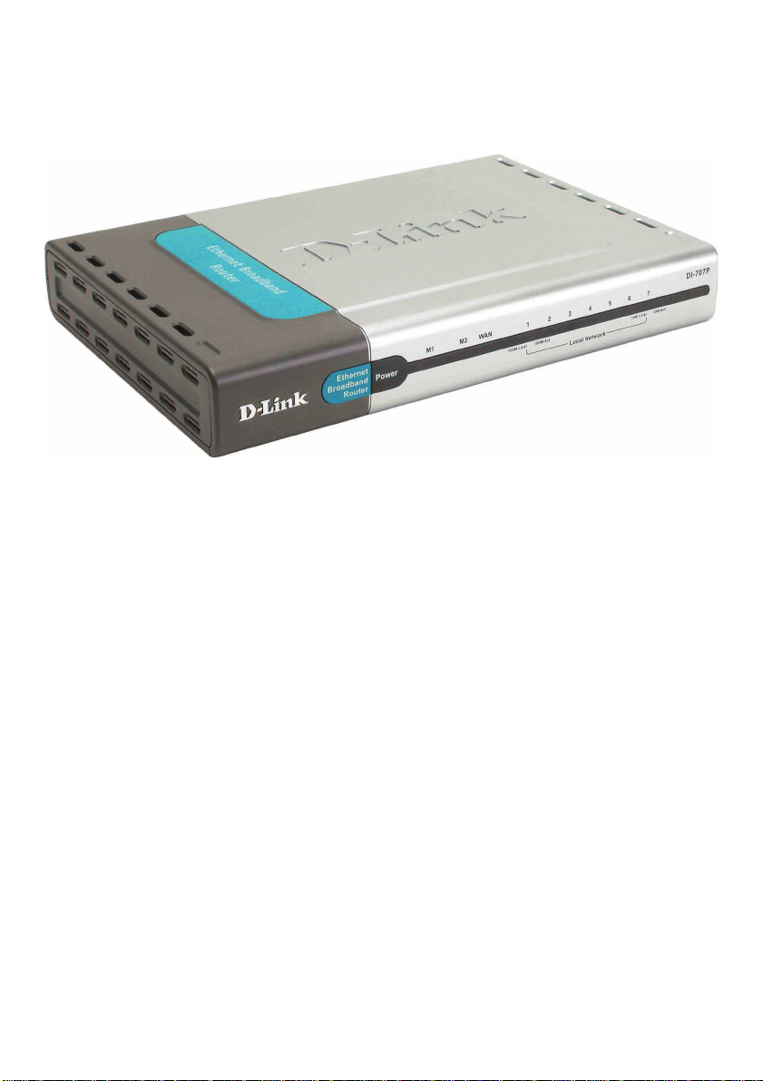
D-Link DI-707P Express EtherNetwork Broadband Router
Power Adapter – 5V AC
Ethernet (CA T5-UTP/Straight-Through) Cable
Manual on CD
Quick Installation Guide
TM
Note: Using a power supply with a different voltage rating than the one included with the
DI-707P will cause damage and void the warranty for this product.
If any of the above items are missing, please contact your reseller.
System Requirements For Configuration:
Computer with Windows, Macintosh, or Linux-based
operating system with an installed Ethernet adapter
Internet Explorer version 6x or Netscape Navigator
version 6x and above, with JavaScript enabled
3
Page 4

Introduction
The D-Link DI-707P Broadband Router includes 7 ports and a printer port. It
provides a complete solution for Internet surfing and office resources sharing.
It is an ideal way to extend the reach and number of computers connected to
your network.
After completing the steps outlined in the Quick Installation Guide (included in
your package), you will have the ability to share information and resources, as
well as share a printer on your network.
The DI-707P is compatible with most popular operating systems, including
Macintosh, Linux, and Windows, and can be integrated into a large network.
4
Page 5
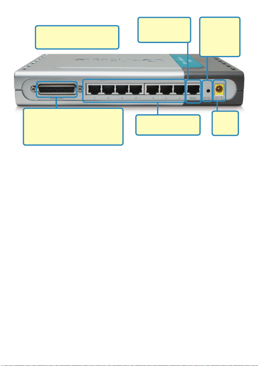
Connections
All LAN ports auto-sense cable
types to accomodate straightthrough or cross-over cable.
WAN port is the
connection for the
Ethernet cable to the
Cable or DSL modem
Pressing the
Reset Button
restores the
router to its
original factory
default settings.
Printer Port. Most printers will work with
this bi-directional printer port. If you
experience difficulties with a multifunctional printer, please confirm that your
printer is compatible with a bi-directional
port.
Features & Benefits
Broadband modem and IP sharing
Connects multiple computers to a broadband (cable or DSL) modem to surf the
Internet.
Auto-sensing Ethernet Switch
Equipped with a 7-port auto-sensing Ethernet switch.
VPN Pass-Through supported
Supports pass-through PPTP sessions and allows you to setup a VPN server
and VPN clients.
Printer sharing (Optional)
Embeds a print server to allow all of the networked computers to share one
printer.
Firewall
All unwanted packets from outside intruders are blocked to protect your
network.
LAN ports provide
connections to Ethernetenabled devices.
Receptor
for the
Power
Adapter
DHCP server supported
All of the networked computers can retrieve TCP/IP settings automatically from
the DI-707P .
Web-based configuration
Configurable through any networked computer’s web browser using Netscape or
Internet Explorer.
5
Page 6

Features & Benefits continued
Access Control supported
Allows you to assign different access rights for different users.
Packet filter supported
Packet Filter allows you to control access to a network by analyzing the
incoming and outgoing packets and letting them pass or halting them based on
the IP address of the source and destination.
Virtual Server supported
Enables you to expose WWW, FTP, and other services on your LAN to be
accessible to Internet users.
User-Definable Application Sensing Tunnel
User can define the attributes to support special applications requiring multiple
connections, such as Internet gaming, video conferencing, Internet telephony
and so on. The DI-707P can sense the application type and open a multi-port
tunnel for it.
DMZ Host supported
Allows a networked computer to be fully exposed to the Internet; this function is
used when the special “application-sensing tunnel feature” is insufficient to allow an application to function correctly .
Introduction to Broadband
Router Technology
A router is a device that forwards data packets from a source to a destination. Routers
forward data packets using IP addresses and not a MAC address. A router will forward
data from the Internet to a particular computer on your LAN.
The information that makes up the Internet gets moved around using routers. When you
click on a link on a web page, you send a request to a server to show you the next page.
The information that is sent and received from your computer is moved from your computer to the server using routers. A router also determines the best route that your information should follow to ensure that the information is delivered properly .
A router controls the amount of data that is sent through your network by eliminating
information that should not be there. This provides security for the computers connected
to your router, because computers from the out side cannot access or send information
directly to any computer on your network. The router determines which computer the
information should be forwarded to and sends it. If the information is not intended for any
computer on your network, the data is discarded. This keeps any unwanted or harmful
information from accessing or damaging your network.
6
Page 7

Introduction to Firewalls
A firewall is a device that sits between your computer and the Internet that prevents
unauthorized access to or from your network. A firewall can be a computer using firewall
software or a special piece of hardware built specifically to act as a firewall. In most
circumstances, a firewall is used to prevent unauthorized Internet users from accessing
private networks or corporate LANs and Intranets.
A firewall watches all of the information moving to and from your network and analyzes
each piece of data. Each piece of data is checked against a set of criteria that the
administrator configures. If any data does not meet the criteria, the data is blocked and
discarded. If the data meets the criteria, the data is passed through. This method is
called packet filtering.
A firewall can also run specific security functions based on the type of application or type
of port that is being used. For example, a firewall can be configured to work with an FTP
or T elnet server . Or a firewall can be configured to work with specific UDP or TCP ports to
allow certain applications or games to work properly over the Internet.
Introduction to Local Area Networking
Local Area Networking (LAN) is the term used when connecting several computers together over a small area such as a building or group of buildings. LANs can be connected
over large areas. A collection of LANs connected over a large area is called a Wide Area
Network (WAN).
A LAN consist s of multiple computers connected to each other . There are many types of
media that can connect computers together. The most common media is a CAT5 cable
(UTP or STP twisted pair wire). On the other hand, wireless networks do not use wires;
instead they communicate over radio waves. Each computer must have a Network Interface Card (NIC), which communicates the data between computers. A NIC is usually a
10Mbps network card, a 10/100Mbps network card, or a wireless network card.
Most networks use hardware devices such as hubs or switches that each cable can be
connected to in order to continue the connection between computers. A hub simply takes
any data arriving through each port and forwards the data to all other ports. A switch is
more sophisticated, in that it can determine the destination port for a specific piece of
data. A switch minimizes network traffic overhead and speeds up the communication
over a network.
Networks take some time to plan and implement correctly. There are many ways to
configure your network. Y ou may want to take some time to determine the best network
set-up for your needs.
7
Page 8

Introduction to Virtual Private Networking
Virtual Private Networking (VPN) uses a publicly wired network (the Internet) to securely
connect two different networks as if they were the same network. For example, an employee can access the corporate network from home using VPN, allowing the employee
to access files and printers. Here are several different implementations of VPN that can
be used.
Point-to-Point Tunneling Protocol (PPTP)
PPTP uses proprietary means of connecting two private networks over the Internet. PPTP
is a way of securing the information that is communicated between networks. PPTP
secures information by encrypting the data inside of a packet.
IP Security (IPSec)
IPSec provides a more secure network-to-network connection across the Internet or a
Wide Area Network (WAN). IPSec encrypts all communication between the client and
the server whereas PPTP only encrypts the data packets.
Both of these VPN implementations are used because there is not a standard for VPN
server software. Because of this, each ISP or business can implement its own VPN
network making interoperability a challenge.
8
Page 9

LEDS
LED stands for Light-Emitting Diode. The DI-707P has the following LEDs
as described below:
LED
Power
M1 LED
M2 LED
WAN
LAN
LOCAL
NETWORK
(Ports 1-7)
LED Activity
A steady light indicates
a connection to a power source. power source
Flashes once per second to indicate an
active system.
Lights up when the device has an Internet
connection.
A solid light indicates connection on the
WAN port. This LED blinks during data
transmission.
This LED blinks during data transmission.
A solid light indicates a connection to an
Ethernet-enabled computer on ports 1-7. This
LED blinks during data transmission.
9
Page 10
Getting Started
With its default settings, the DI-707P, when activated, will connect with
other D-Link Express EtherNetwork products, right out of the box.
11
1
11
Please refer to the following
sections of this manual for
additional information about
setting up a network:
Networking Basics - learn
how to check and assign your
IP Address; share printers and
files.
Using the Configuration
Menu - learn the settings for
the DI-707P, using the webbased interface.
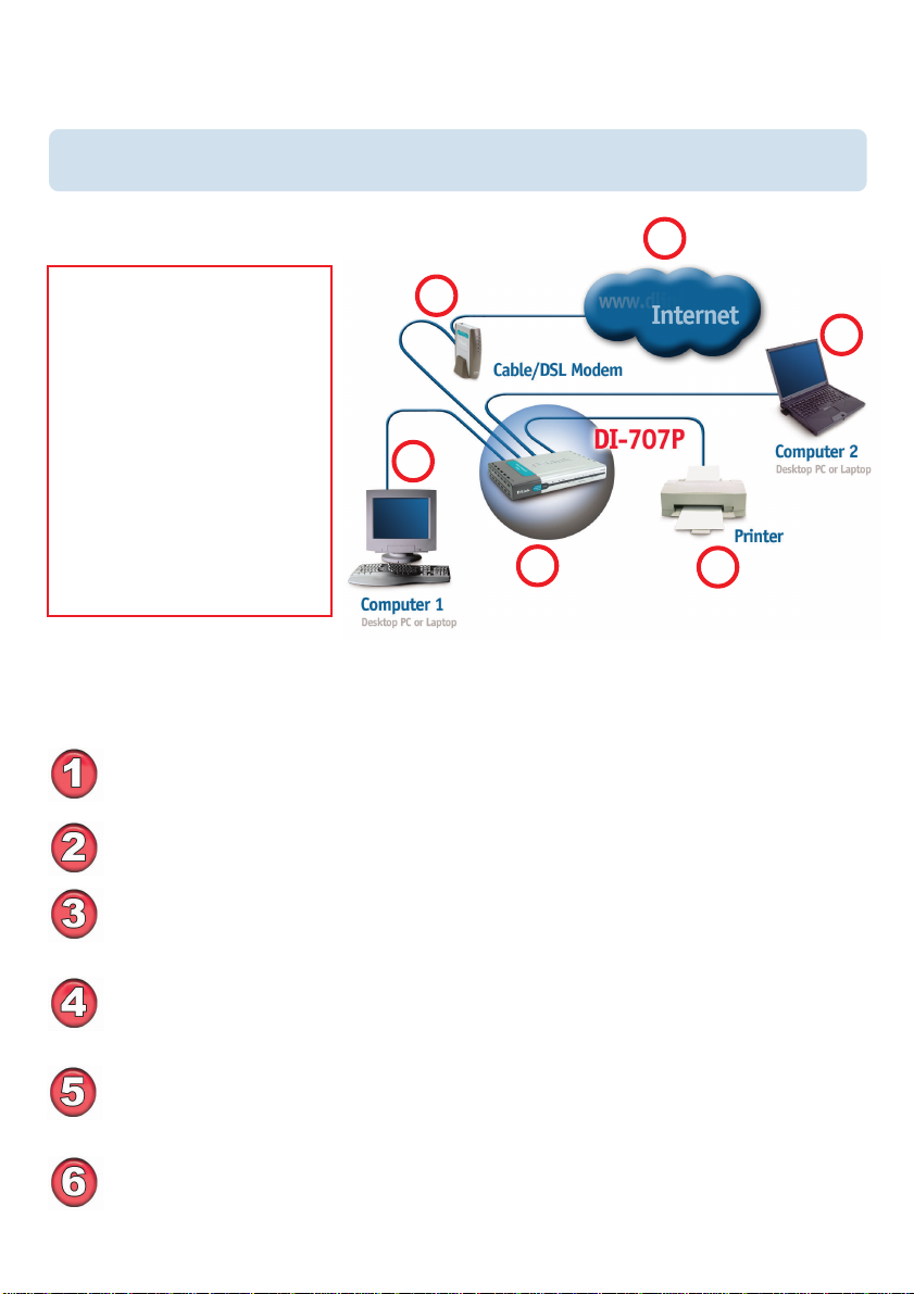
For a typical network setup at home (as shown above), please do the
following:
Y ou will need broadband Internet access (a Cable or DSL subscription line into
your home or office).
Consult with your Cable or DSL provider for proper installation of the modem.
Connect the Cable or DSL modem to the DI-707P wireless broadband router
(see the Quick Installation Guide included with the DI-707P).
22
2
22
44
4
44
33
3
33
66
6
66
55
5
55
If you are connecting a desktop computer to your network, you can install the
D-Link DFE-530TX+ ethernet adapter into an available PCI slot. (See the
Quick Installation Guide included with the DWL-530TX+.)
If you are connecting a laptop computer to your network, install the drivers for
the Ethernet Cardbus adapter (e.g., D-Link DFE-690TXD) into a laptop
computer.(See the Quick Installation Guide included with the DFE-690TXD.)
Connect your printer to the printer port on the DI-707P . Please refer to the
quick installation guide for loading the print server software.
10
Page 11
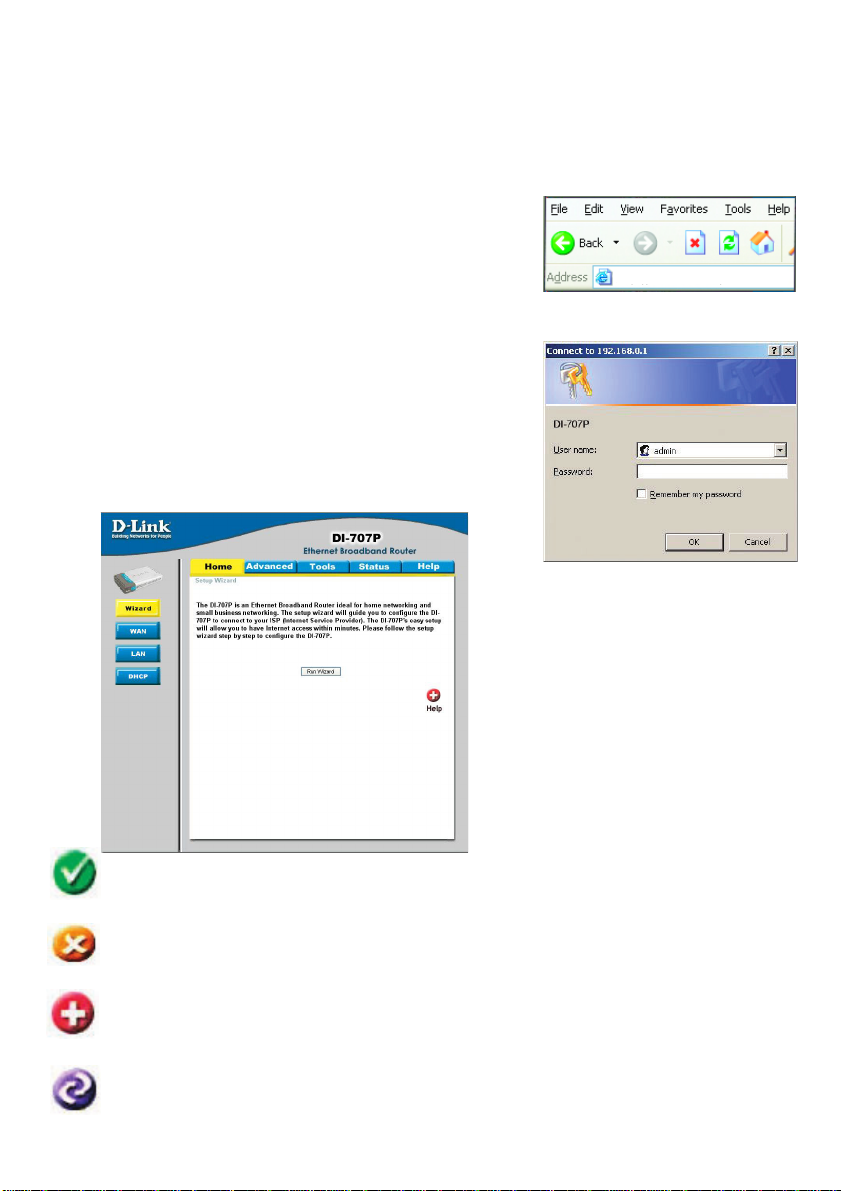
Using the Configuration Menu
Whenever you want to configure your network or the DI-707P , you can access the
Configuration Menu by opening the web-browser and typing in the IP Address of the
DI-707P . The DI-707P default IP Address is shown below:
Open the web browser
Type in the IP Address of
the DI-707P
Note: if you have changed the default IP Address assigned to the DI-707P, make sure to
enter the correct IP Address.
The factory default User name is admin and the default
Password is blank (empty). It is recommended that you
change the admin password for security purposes. Please
refer to Tools>Admin to change the admin password.
Home > Wizard
The Home>Wizard screen will
appear. Please refer to the
Quick Installation Guide for
more information regarding the
Setup Wizard.
http://192.168.0.1
Apply
Cancel
Help
Clicking Apply will save changes made to the page.
Clicking Cancel will clear changes made to the page.
Clicking Help will bring up helpful information regarding the page.
Clicking Restart will restart the router. (Necessary for some changes.)
11
Page 12
Using the Configuration Menu
Home > WAN
Choose WAN Type
WAN stands for Wide Area Network. In this case WAN represents the mode in which
you connect to the Internet. If you are uncertain, please ask your ISP which of the
following represents your connection mode to the Internet:
Dynamic
IP Address-
Static IP Address-
PPP over
Ethernet-
Others-
PPTPBig Pond Cable-
Obtain an IP address from your ISP automatically (mainly for
Cable users).
Your ISP assigns you a Static IP Address.
Some ISPs require the use of PPPoE to connect to their
services (mainly for DSL users).
For use in Europe only .
For use in Australia only.
12
Page 13
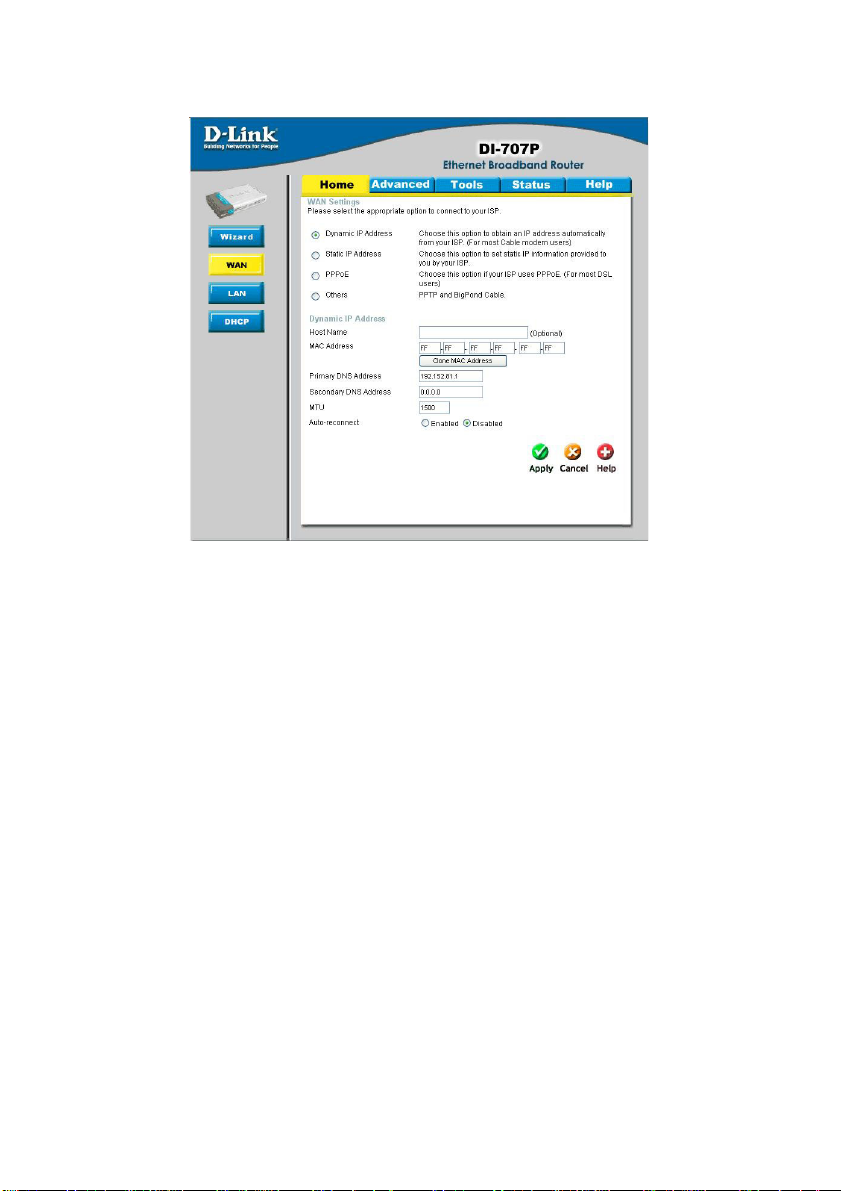
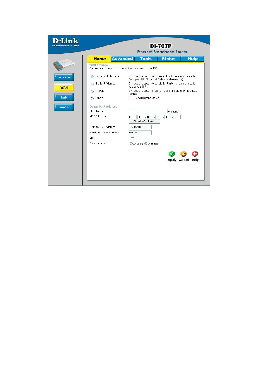
Using the Configuration Menu
Home > W AN > Dynamic IP Address
Most Cable modem users will select this option to obtain an IP
from their ISP (Internet Service Provider).
Host Name-
MAC Address-
This is optional, but may be required by some ISPs. The host
name is the device name of the Router.
The default MAC Address is set to the WAN’s physical interface
MAC address on the Router.
Clone
MAC Address-
This feature will copy the MAC address of the Ethernet card, and
replace the WAN MAC address of the Router with this Ethernet
card MAC address. It is not recommended that you change the
default MAC address unless required by your ISP .
Primary DNS
Address-
Input the primary DNS address provided by your ISP
Secondary DNS
Address-
MTU-
Auto-reconnect -
(Optional) Input the Secondary DNS address provided by your ISP .
Maximum Transmission Unit; default is 1500; you may need to
change the MTU to conform to your ISP.
If enabled, the Broadband Router will automatically connect to
your ISP after your system is restarted or if the connection is
dropped.
Address automatically
13
Page 14
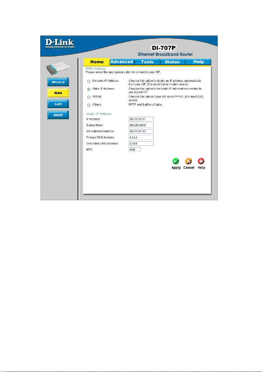
Using the Configuration Menu
Home > WAN > S t atic IP Address
If you use a St atic IP Address, you will input information here that your ISP has provided
to you.
IP Address-
Subnet Mask-
ISP Gateway-
Input the IP Address provided by your ISP.
Input the Subnet Mask provided by your ISP .
Input the Gateway address provided by your ISP .
Primary DNS
Address-
Secondary DNS
Address-
MTU-
Input the primary DNS address provided by your ISP .
(Optional) Input the Secondary DNS address provided by your
ISP.
Maximum T ransmission Unit; default is 1500; you may need to
change the MTU to conform to your ISP.
14
Page 15
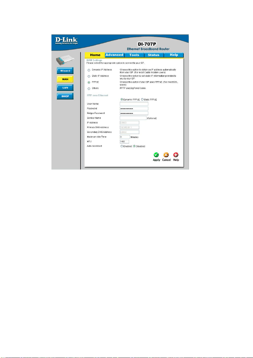
Using the Configuration Menu
Home > WAN > PPPoE
Most DSL users will select this option to obtain an IP address automatically from their
ISP through the use of PPPoE.
User Name-
Y our PPPoE username provided by your ISP
PasswordService Name-
IP Address-
Primary DNS
Address-
Maximum
Idle Time-
MTU-
Auto-reconnect -
Y our PPPoE password is provided by your ISP
(Optional) Check with your ISP for more information if they
require the use of service name.
(Optional) Enter in the IP Address if you are assigned a static
PPPoE address.
Y ou will get the DNS IP automatically from your ISP but you
may enter a specific DNS address that you want to use instead.
(Optional) Input the secondary DNS address
Enter a maximum idle time during which Internet connection is
maintained during inactivity . T o disable this feature, enable Auto-
reconnect.
Maximum T ransmission Unit; default is 1492; you may need to
change the MTU to conform to your ISP .
If enabled, the Broadband Router will automatically connect to
your ISP after your system is restarted or if the connection is
dropped.
15
Page 16
Using the Configuration Menu
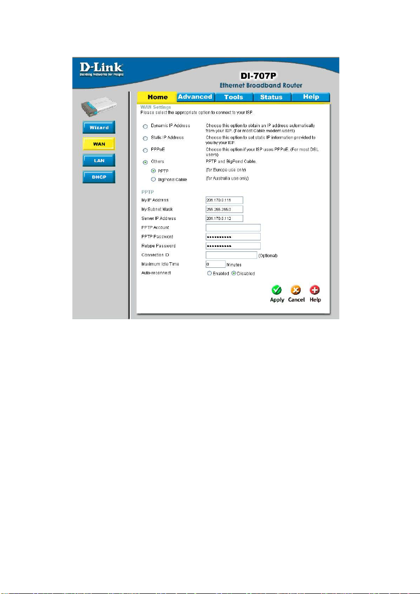
Home > WAN > PPTP
Point-to-Point Tunneling Protocol (PPTP) is a WAN connection used in Europe.
My IP Address-
My Subnet MaskServer IP Address-
PPTP Account-
PPTP Password-
Connection IDMaximum
Idle Time-
Auto-reconnect -
Enter the IP Address.
Enter the Subnet Mask.
Enter the Server IP Address.
Enter the PPTP account name.
Enter the PPTP password.
(Optional) Enter the connection ID if required by your ISP .
Enter a maximum idle time during which Internet connection is
maintained during inactivity . T o disable this feature, enable Auto-
reconnect.
If enabled, the Broadband Router will automatically connect to
your ISP after your system is restarted or if the connection is
dropped.
16
Page 17
Using the Configuration Menu
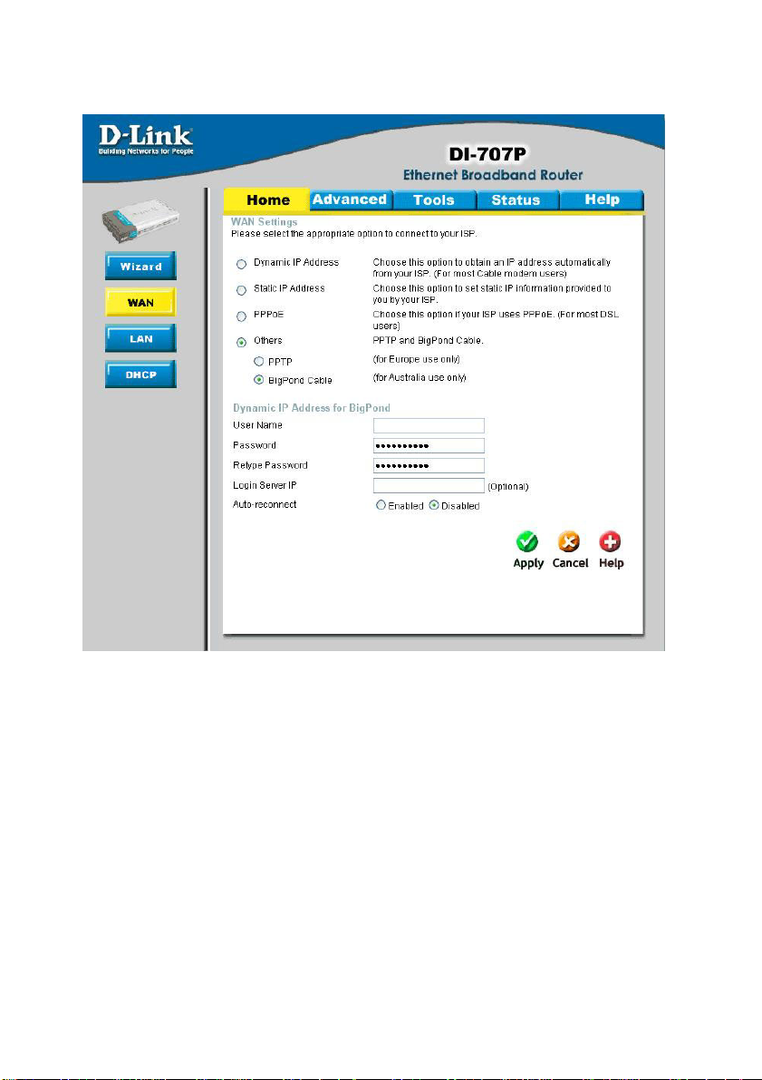
Home > WAN > BigPond Cable
Dynamic IP Address for BigPond is a W AN connection used in Australia.
User Name-
Password-
Login Server-
Auto-reconnect -
Enter in the username for the BigPond account.
Enter the password for the BigPond account.
(Optional) Enter the Login Server name if required.
If enabled, the Broadband Router will automatically connect to
your ISP after your system is restarted or if the connection is
dropped.
17
Page 18
Using the Configuration Menu
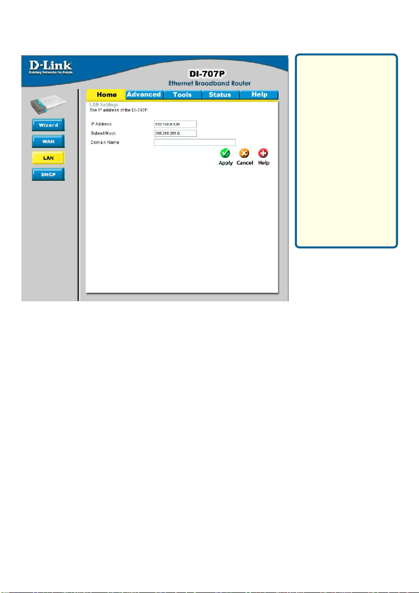
Home > LAN
LAN is short for Local
Area Network. This is
considered your internal network. These
are the IP settings of
the LAN interface for
the DI-707P. These
settings may be referred to as Private
settings. You may
change the LAN IP
address if needed.
The LAN IP address
is private to your internal network and cannot be seen on the
Internet.
DHCP stands for Dynamic Host Control Protocol. The DI-707P has a built-in DHCP
server. The DHCP Server will automatically assign an IP address to the computers on
the LAN/private network. Be sure to set your computers to be DHCP clients by setting
their TCP/IP settings to “Obtain an IP Address Automatically.” When you turn your
computers on, they will automatically load the proper TCP/IP settings provided by the
DI-707P. The DHCP Server will automatically allocate an unused IP address from the IP
address pool to the requesting computer. You must specify the starting and ending
address of the IP address pool.
IP Address-
Subnet Mask-
Domain Name-
The IP address of the LAN interface.
The default IP address is: 192.168.0.1.
The subnet mask of the LAN interface.
The default subnet mask is 255.255.255.0.
(Optional) The name of your local domain.
18
Page 19
Using the Configuration Menu
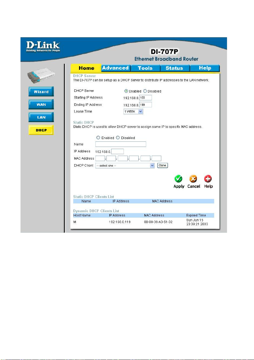
Home > DHCP
DHCP stands for Dynamic Host Control Protocol. The DI-707P has a built-in DHCP
server. The DHCP Server will automatically assign an IP address to the computers on
the LAN/private network. Be sure to set your computers to be DHCP clients by setting
their TCP/IP settings to “Obtain an IP Address Automatically.” When you turn your
computers on, they will automatically load the proper TCP/IP settings provided by the
DI-707P . The DHCP Server will automatically allocate an unused IP address from the
IP address pool to the requesting computer . You must specify the starting and ending
address of the IP address pool.
19
Page 20
Using the Configuration Menu
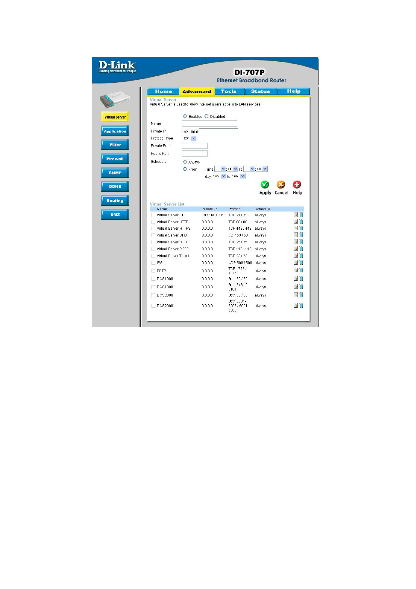
Advanced > Virtual Server
The DI-707P can be configured as a virtual server so that remote users accessing Web
or FTP services via the public IP address can be automatically redirected to local servers
in the LAN (Local Area Network).
The DI-707P firewall feature filters out unrecognized packets to protect your LAN network
so all computers networked with the DI-707P are invisible to the outside world. If you
wish, you can make some of the LAN computers accessible from the Internet by enabling
Virtual Server. Depending on the requested service, the DI-707P redirects the external
service request to the appropriate server within the LAN network.
Enable-
Select to activate the policy .
Name- Y ou can name the Virtual Server .
Private IP- The IP address of the internal computer that will be using the
virtual service.
Protocol Type- Select the protocol the Virtual Server will use.
Private/ Public
Ports-
Enter in the private and public port or ports to be used. A range
of ports can be specified with a hyphen. (e.g., 20-21)
Schedule- Select Always, or choose From and enter the time period dur-
ing which the virtual service will be available.
20
Page 21
Using the Configuration Menu
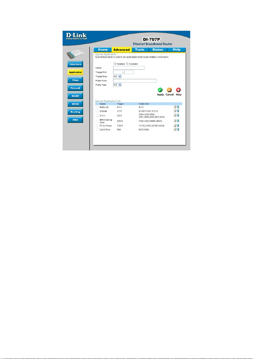
Advanced > Application
Some applications require multiple connections, such as Internet gaming, video
conferencing, and Internet telephony . These applications have difficulties working through
NAT (Network Address Translation). Special Applications makes some of these
applications work with the DI-707P. If you need to run applications that require multiple
connections, specify the port normally associated with an application in the Trigger
field, then enter the public ports associated with the trigger port into the Incoming
Ports field.
At the bottom of the screen, there are already defined special applications. T o use them,
select one from the drop down list and select an ID number you want to use. Then click
the “Copy to” button and the router will fill in the appropriate information to the list. Y ou
will then need to enable the service. If the mechanism of Special Applications fails to
make an application work, try using DMZ host instead.
Note! Only one PC can use each Special Application tunnel.
EnableName-
Trigger PortTrigger Type-
Public Ports-
Public Type-
Select to activate the policy .
Y ou can name the defined special applications.
This is the port used to trigger the application. It can be either
a single port or a range of ports.
Select the trigger protocol you would like to initiate. To chage
the selection, use the drop down arrow and other choices will
be listed.
This is the port number on the WAN side that will be used to
access the application. Y ou may define a single port or a range
of ports. You can use a comma to add multiple ports or port
ranges.
Select the public type the special application will use.
21
Page 22
Using the Configuration Menu
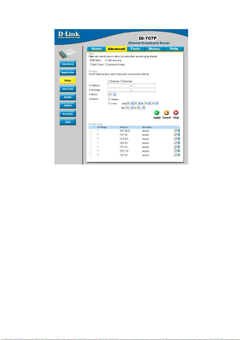
Advanced > IP Filter
Use IP (Internet Protocol) filters to allow or deny computers access to the Internet based
on their IP address.
Disabled IP FilterEnabled or Disabled- Click Enabled to apply the filter policy or click Disabled to
IP Address- Enter the IP address range of the computers that you want the
Port Range-
Protocol-
Schedule-
Select this option if you do not want to use IP filters.
enter an inactive filter policy. (You can reactivate the policy
later.)
policy to apply to. If it is only a single computer that you want
the policy applied to, then enter the IP address of the computer
in the Start Source IP and leave the End Source IP blank.
Enter in the port range of the TCP/UDP ports that you want the
policy to apply to. If it is only a single port that you want the
policy applied to, then enter the port number in the Start Port
field and leave the End Port field blank. If you want to use all the
ports, you can leave the port range empty .
Select the protocol the IP filter will use.
Select Always, or choose From and enter the time period dur-
ing which the IP filter policy will be in effect.
22
Page 23
Using the Configuration Menu
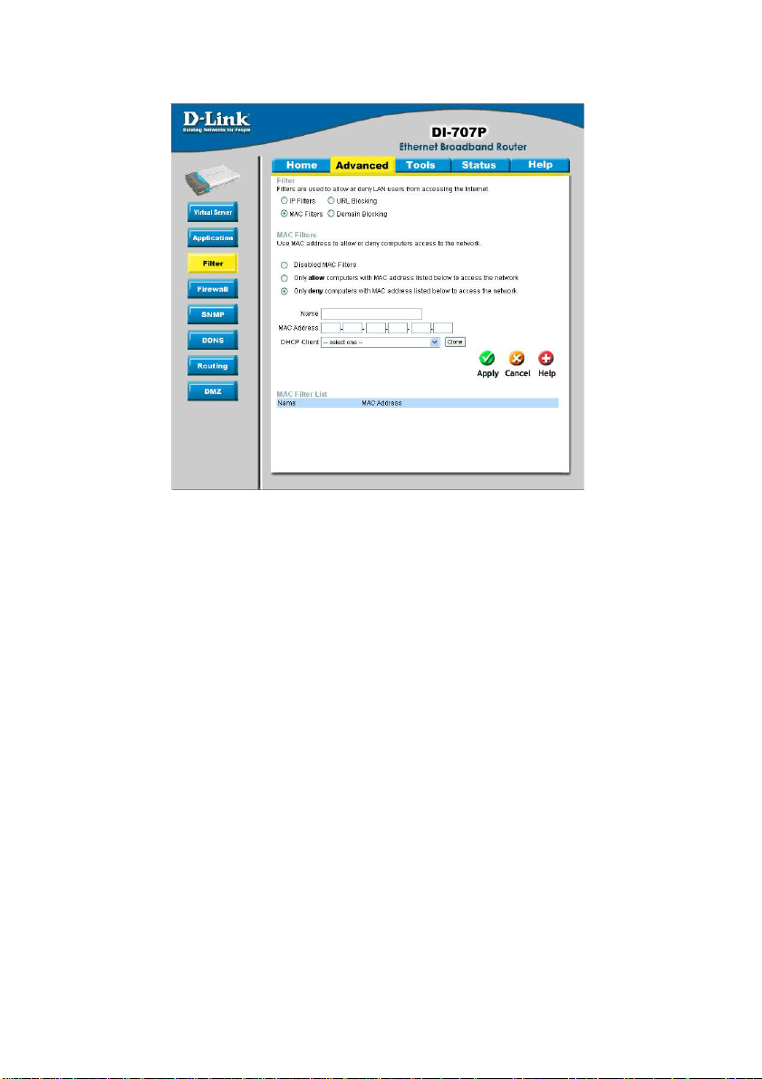
Advanced > MAC Filters
MAC (Media Access Control) Filters are used to deny or allow LAN (Local Area Network)
computers from accessing the Internet and network by their MAC address.
At the bottom of the screen, there is a list of MAC addresses from the DHCP client
computers connected to the DI-707P. To use them, select one from the drop down list
and select an IP number you want to use. Then click the “Copy to” button and the
DI-707P will fill in the appropriate information in the list.
Disabled MAC Filter- Select this option if you do not want to use MAC filters.
Only allow computers with MAC address listed below to access the network-
Select this option to only allow computers that are in the list
to access the network and Internet. All other computers will
be denied access to the network and Internet.
Only deny computers with MAC address listed below to access the network-
Select this option to only deny computers that are in the list
to access the network and Internet. All other computers will
be allowed access to the network and Internet.
Name- Enter a name to create a profile for the associated
computer(s) on the network.
MAC AddressEnable-
Disabled MAC Filter-
Enter the MAC Address of the client that will be filtered.
Select this option for the specific IP filter policy to take effect.
Select from the DHCP Client list and click the Clone button to
automatically clone that computer’s MAC address to the MAC
address field.
23
Page 24
Using the Configuration Menu
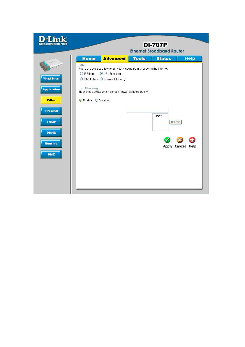
Advanced > URL Blocking
Use URL Blocking to deny LAN computers from accessing specific web sites by its
URL. A URL is a specially formatted text string that defines a location on the Internet.
If any part of the URL contains the blocked word, the site will not be accessible and
the web page will not display .
Disabled URL Blocking-
Select this option if you do not want to use URL Blocking.
24
Page 25
Using the Configuration Menu
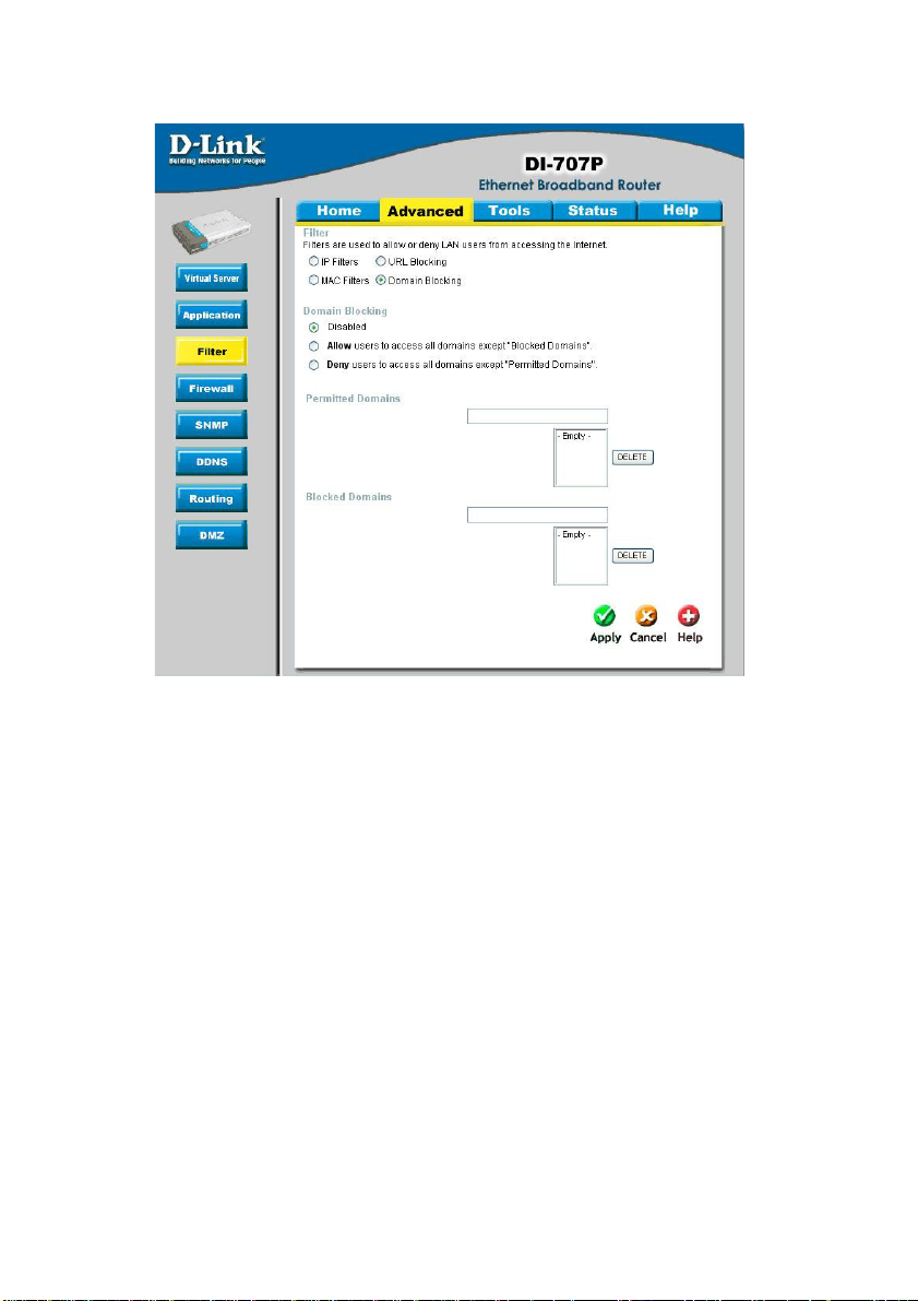
Advanced > Domain Filter
Use Domain filters to allow or deny computers access to specific Internet domains
whether it is through www, ftp, snmp, etc. Domain filters apply to both wired computers
connected to one of the four Ethernet LAN ports and to wireless clients connected
wirelessly to the DI-707P .
Disabled Domain Filter- Select this option if you do not want to use Domain filters.
Allow users to access the following domains and block all other domains-
Select this option to allow users to access the specified
Internet domains listed below. Users will be denied access
to all other Internet domains.
Deny users to access the following domains and permit all other domains-
Select this option to deny users access to the specified
Internet domains listed below. Users will be allowed access
to all other Internet domains.
Permitted/Blocked Domains-
This is a list of domain suffixes of the Internet domain you
want to permit or block. (Example: shopping.com,
sports.net.)
25
Page 26
Using the Configuration Menu
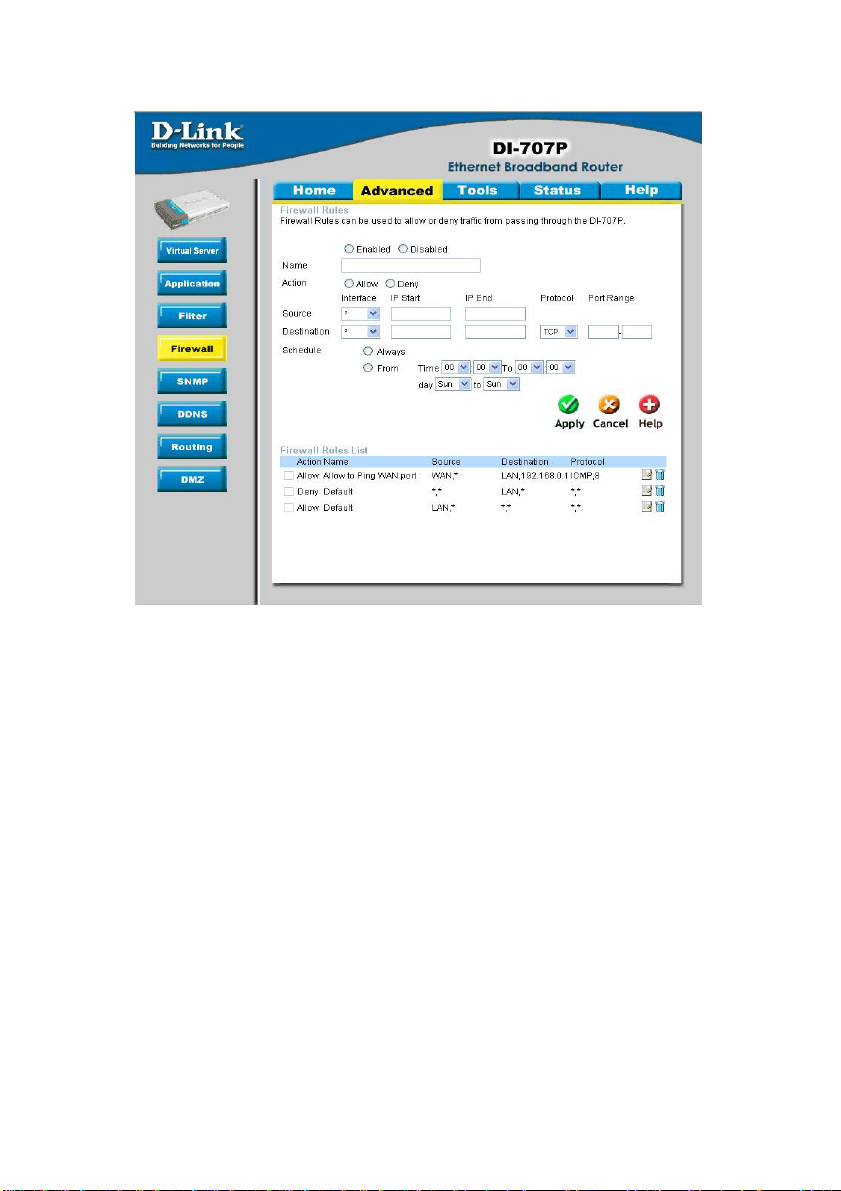
Advanced > Firewall
Firewall Rules is an advance feature used to deny or allow traffic from passing through
the device. It works in the same way as IP Filters with additional settings. You can
create more detailed rules for the device.
Enabled or Disabled-
Click Enabled to apply the filter policy or click Disabled to enter an inactive filter policy
(Y ou can reactivate the policy later).
Name-
Enter the name of the Firewall Rule.
Action-
Select Allow or Deny to allow or deny traf fic to pass through the DI-804HV .
Interface Source -
Choose between a LAN or WAN source. An asterisk signifies the selection of both
sources.
Interface Destination-
Choose between a LAN or WAN destination. An asterisk signifies the selection of both
destinations.
IP Start-
The starting IP address for the filter policy . Leaving the field blank selects all IPs.
IP End-
The ending IP address for the filter policy . Leaving the field blank sleects all IPs.
26
Page 27
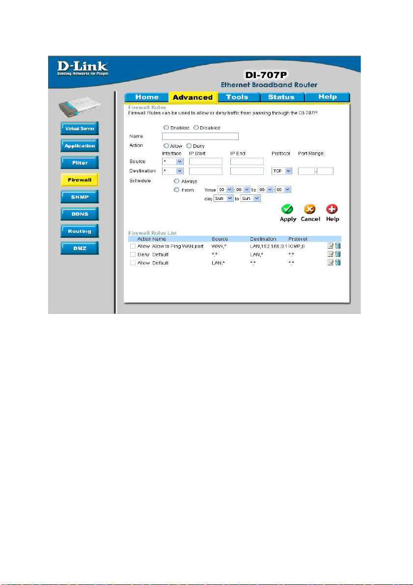
Using the Configuration Menu
Advanced > Firewall Continued
Protocol-
Select one of the following protocols: TCP, UDP, or ICMP.
Port Range-
Enter in the port range of the TCP/UDP ports that you want the policy to apply to. If it is
only a single port that you want the policy applied to, then enter the port number in the
St art Port field and leave the End Port field blank. If you want to use all the ports, you
can leave the port range empty .
Schedule-
Select Always, or choose From and enter the time period during which the virtual ser-
vice will be available
27
Page 28
Using the Configuration Menu
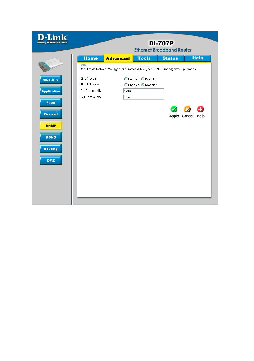
Advanced > SNMP
SNMP (Simple Network Management Protocol) is a widely used network monitoring and
control protocol that reports activity on each network device to the administrator of the
network. SNMP can be used to monitor traffic and statistics of the DI-707P. The DI707P supports SNMP v1.
Enable SNMP-
Local-
Remote-
Get Community-
Set Community-
(Simple Netwokkr Management Protocol)
LAN (Local Area Network)
WAN (Wide Area Network)
Enter the password public in this field to allow “Read only” access to the network administration using SNMP. You can view
the network, but no configuration is possible with this setting.
Enter the password private in this field to gain “Read and Write”
access to the network using SNMP software. The administrator
can configure the network with this setting.
28
Page 29
Using the Configuration Menu
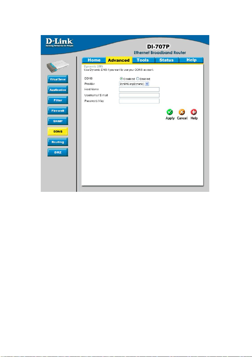
Advanced > DDNS
DDNS (Dynamic Domain Name System) keeps dynamic IP addresses (e.g., IP addresses assigned by a DHCP capable router or server) linked to a domain name. Users
who have a Dynamic DNS account may use this feature on the DI-707P.
DDNS-
Provider-
Host Name-
Username/Email-
Password/Key-
When an IP address is automatically assigned by a DHCP server ,
DDNS automatically updates the DNS server. Select Disabled
or Enabled.
Select from the pull-down menu.
Enter the Host name.
Enter the username/email address.
Enter the password/key .
29
Page 30
Using the Configuration Menu
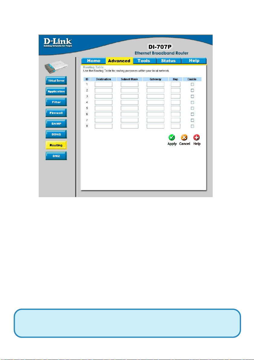
Advanced > Routing
Static routes can be added if you require specific routes within your internal network.
These routes will not apply to the WAN (Internet) network.
Destination- Enter in the IP of the specified network that you want to
access using the static route.
Subnet Mask- Enter in the subnet mask to be used for the specified net
work.
Gateway- Enter in the gateway IP address to the specified network.
Hop- Enter in the amount of hops it will take to the specified
network.
Enable- Select this option for the specified static route to take effect.
Hop Count - In a transmission path, each link is terminated at a network device
such as a router or gateway . The number of hops equals the number of routers or
gateways that data must pass through before reaching the destination.
30
Page 31

Using the Configuration Menu
Advanced > DMZ
If you have a computer that cannot run Internet applications properly from behind the
DI-707P, then you can allow that computer to have unrestricted Internet access. Enter
the IP address of that computer as a DMZ (Demilitarized Zone) host with unrestricted
Internet access. Adding a client to the DMZ may expose that computer to a variety of
security risks, so only use this option as a last resort.
31
Page 32

Using the Configuration Menu
T ools> Admin
You can change the admin password here. It is recommended that you change the
admin password from the default setting. The default password is blank (no password).
PasswordRemote
Management-
IP Address-
Port-
T o change the admin password, enter in the old p assword, and
enter the new password twice to confirm.
Remote Management allows the device to be configured through
the WAN (Wide Area Network) port from the Internet using a
web browser. A username and password is still required to
access the browser-based management interface.
Internet IP Address of the computer that has access to the
DI-707P . If the IP Address is set to 0.0.0.0, this allows all Internet
IP addresses to access the DI-707P.
The port number used to access the DI-707P .
E.g., http://x.x.x.x:80, where x.x.x.x. is the WAN IP address of
the DI-707P and 80 is the port used for the Web Management
interface.
32
Page 33

Using the Configuration Menu
Tools> Time
Set the time here by entering it manually or by using NTP (Network Time Protocol.) NTP
is a standard protocol on the Internet that sychronizes the time settings accurately for
all the computers on your network.
Enable NTP-
Default NTP
server-
Time Zone- Select your time zone from the pull-down menu.
Set Device Date
and Time-
Select to enable NTP and synchronize the time settings on your
network using an NTP server .
If you are enabling NTP , please enter the link to the default server .
If you are entering the time manually, select the correct Year,
Month, Day , Hour, Minute, and Second.
33
Page 34

Using the Configuration Menu
Tools > System
The current system settings can be saved as a file onto the local hard drive. The saved
file or any other saved setting file created by the DI-707P can be uploaded to the unit. To
reload a system settings file, click on Browse to search the local hard drive for the file
to be used. The device can also be reset back to factory default settings by clicking on
the Reset to Default button. Use the restore feature only if necessary. This will erase
previously saved settings for the unit. Make sure to save your system settings to the
hard drive before doing a factory restore.
Save Settings to
Local Hard Drive-
Load Settings from
Local Hard Drive-
Restore to Factory
Default Settings-
Click Backup Setting to save the current settings to the local
Hard Drive.
Click Browse to find the settings file, then click Load.
Click Reset to Default to restore the factory default settings.
34
Page 35

Using the Configuration Menu
Tools > Firmware
Y ou can upgrade the firmware by using this tool. First, check the D-Link support site for
firmware updates at http://support.dlink.com. Make sure that the firmware you want to
use is saved on the local hard drive of your computer. Click on Browse to search the
local hard drive for the firmware that you downloaded from the D-Link website to be used
for the update. Upgrading the firmware will not change any of your system settings but
it is recommended that you save your system settings before doing a firmware upgrade.
Browse-
Note: Do not power off the unit when it is being upgraded. When the
upgrade is complete, the unit will automatically restart.
After you have downloaded the new firmware, click Browse in
this window to locate the firmware update on your hard drive.
Click Apply to complete the firmware upgrade.
35
Page 36

Using the Configuration Menu
Tools > Misc
36
Page 37

Using the Configuration Menu
Tools > Misc Continued
Ping Test-
Restart DeviceBlock WAN Ping-
SPI Mode-
UPnP Setting-
VPN Pass Through-
Non-standard FTP port-
This useful diagnostic utility can be used to check if a
computer is on the Internet. It sends ping packets and
listens for replies from the specific host.
Click reboot to restart the unit.
Click Enable to block the WAN ping. Computers on the
Internet will not get a reply back from the DI-707P when it is
being “ping”ed. This may help to increase security.
Stateful Packet Inspection is a form of firewall protection that
will inspect all of the packets transmitted through the DI707P. It carefully inspects all incoming packets and if it packets contain suspecious information, it will automatically drop
those packets.
Universal Plug and Play is a feature that is preset to allow
certain popular applications such as MSN messenger to be
functional using the router without making any configurations.
By default UPnP setting is set to enable. It is recommended
to keep UPnP Setting on enable.
For users who telecommute or use Virtual Private Network
(VPN), you can select PPTP or IPSec to be used with this
router.
If an FTP server you want to access is not using the standard port 21, then enter in the port number that the FTP
server is using instead.
37
Page 38

Using the Configuration Menu
Status > Device Info
This screen displays information about the DI-707P .
DHCP Renew-
DHCP Release-
Click to refresh IP addresses sent from the DHCP server .
Click to release IP addreses sent from the DHCP server .
38
Page 39

Using the Configuration Menu
Status > Log
This screen displays activities occurring on the DI-707P .
First Page-
Last Page-
Previous-
Next-
Clear-
Log Settings-
Click First Page to go to the first page of the log.
Click Last Page to go to the last page of the log.
Click Previous to go to the previous page of the log.
Click Next to go to the next page of the log.
Click Clear to clear the current page of the log.
Click for advanced features (see next page.)
39
Page 40

Using the Configuration Menu
Status > Log Settings
E-Mail Alert-
SMTP Server IP-
Email Address-
Send Mail Now-
Syslog Server IP
Address-
Log T ype- Select the types of activity to log. By default, all values are
The DI-707P can be set up to send the log files to a specific
email address.
Enter in the IP address of the mail server.
Enter in the email address of the recipient who will receive the
email log.
Click to send mail immediately .
Enter in the IP address of a syslog server within the network.
Click Enable to activate the policy. The DI-707P will send all of
it’s logs to the specified syslog server .
selected.
40
Page 41

Using the Configuration Menu
Status > Stats
In Stats section, traffic statistics are displayed.
Refresh-
Reset-
WAN-
LAN-
This will update the page.
This will reset the packet counter to zero.
Displays Received / Transmitted packets from the WAN port.
Displays Received / Transmitted packets from the LAN port.
41
Page 42

Using the Configuration Menu
Help
This screen displays the complete Help menu. For help at anytime, click the Help tab in
the Configuration menu.
42
Page 43

Installing the Print Server Sof tware
Insert the installation CD-ROM into the CD-ROM drive. The following window will be
shown automatically . If it is not, please run “install.exe” on the CD-ROM.
Click Install Print
Server Software
Select the
Operating System
Click Next
43
Page 44

Installing the Print Server Sof tware (continued)
Select the destination folder.
Click Browse to
select a destination
folder
Click Next
Click Finish
Select the
option for
restarting the
computer.
Click OK
After rebooting your computer , the software installation procedure is finished.
44
Page 45

Configuring on Windows 98SE/ME Platforms
After you finish the software installation procedure, your computer will be capable of network
printing provided by the DI-707P. For convenience, we call the printer connected to the
printer port of the DI-707P a print server. On a
Windows 95/98 platform, open the Printers
window in the My Computer menu.
Now, you can configure the print server of
the DI-707P:
Find out the corresponding icon of your print
server, for example, the HP LaserJet 6L.
Right click on that icon, and then select
Properties.
The screen at right appears.
Click on the
Details tab
Choose the “PRTmate: (All-in-1)” from
the list attached at the Print To item.
Be sure that the Printer Driver item
is configured to the correct driver of
your printer server.
Click Port Settings
Type in the IP address of the
DI-707P.
Click OK
45
Page 46

Configuring on Windows XP/2000/NT Platforms
Click Port
The configuration procedure for a Windows
2000/XP platform is similar to that of Windows 95/98 except for the printer Proper-
ties screen:
Click Configure Port
Type in the IP address of the
DI-707P.
Click OK
(Note: Screen shots are taken in Windows 2000, similar
screens will appear in Windows XP.)
46
Page 47

Networking Basics
Using the Network Setup Wizard in Windows XP
In this section you will learn how to establish a network at home or work,
using Microsoft Windows XP.
Note: Please refer to websites such as
and http://www.microsoft.com/windows2000 for information about networking
computers using Windows 2000, ME or 98.
Go to Start>Control Panel>Network Connections
Select Set up a home or small office network
http://www.homenethelp.com
When this screen appears, Click Next.
47
Page 48

Networking Basics
Please follow all the instructions in this window:
Click Next.
In the following window, select the description that best fits your computer. If
your computer connects to the internet through a gateway/router, select the
second option as shown.
Click Next.
48
Page 49

Networking Basics
Enter a Computer description and a Computer name (optional).
Click Next.
Enter a Workgroup name. All computers on your network should have the
same Workgroup name.
Click Next.
49
Page 50

Networking Basics
Please wait while the Network Setup Wizard applies the changes.
When the changes are complete, click Next.
Please wait while the Network Setup Wizard configures the computer.
This may take a few minutes.
50
Page 51

Networking Basics
In the window below, select the option that fit s your needs. In this example, Create a
Network Setup Disk has been selected. You will run this disk on each of the
computers on your network. Click Next.
Insert a disk into the Floppy Disk Drive, in this case drive A.
51
Page 52

Networking Basics
Please read the information under Here’s how in the screen below . After you complete
the Network Setup Wizard you will use the Network Setup Disk to run the Network
Setup Wizard once on each of the computers on your network. T o continue click Next.
52
Page 53

Networking Basics
Please read the information on this screen, then click Finish to complete the Network
Setup Wizard.
The new settings will take effect when you restart the computer. Click Yes to
restart the computer.
You have completed configuring this computer. Next, you will need to run the
Network Setup Disk on all the other computers on your network. Af ter running
the Network Setup Disk on all your computers, your new wireless network
will be ready to use.
53
Page 54

Networking Basics
Naming your Computer
T o name your computer , please follow these directions. In W indows XP:
Click Start (in the lower left corner of the screen).
Right-click on My Computer.
Select Properties and click.
Select the Computer
Name Tab in the System
Properties window.
Y ou may enter a Computer Description if you
wish; this field is optional.
T o rename the computer
and join a domain, Click
Change.
54
Page 55

Networking Basics
Naming your Computer
In this window, enter the
Computer name.
Select Workgroup and enter
the name of the Workgroup.
All computers on your network
must have the same
Workgroup name.
Click OK.
Assigning a Static IP Address in Windows XP/2000
OK
Note: Residential Gateways/Broadband Routers will automatically assign IP Addresses to the computers on the network, using DHCP (Dynamic Host Configuration Protocol) technology. If you are using a DHCP-capable Gateway/Router you
will not need to assign Static IP Addresses.
If you are not using a DHCP capable Gateway/Router , or you need to assign a S tatic IP
Address, please follow these instructions:
Go to Start.
Double-click on
Control Panel.
55
Page 56

Networking Basics
Assigning a Static IP Address in Windows XP/2000
Double-click on
Network
Connections.
Right-click on Local Area
Connections.
Double-click on
Properties.
56
Page 57

Networking Basics
Assigning a Static IP Address
in Windows XP/2000
Click on Internet
Protocol (TCP/IP).
Click Properties.
Enter the LAN IP address of
the Wireless Router. (D-Link
wireless routers have a LAN IP
address of 192.168.0.1.)
The DNS server information will
be supplied by your ISP (Internet
Service Provider).
Click OK
192 168 0 1
192 168 0 1
57
Page 58

Networking Basics
Assigning a Static IP Address with Macintosh OSX
Go to the Apple Menu and se-
lect System Preferences.
cClick on Network.
Select Built-in Ethernet in the
Show pull-down menu.
Select Manually in the Con-
figure pull-down menu.
Input the Static IP Address,
the Subnet Mask, and the
Router IP Address in the ap-
propriate fields.
Click Apply Now.
58
Page 59

Networking Basics
Selecting a Dynamic IP Address with Macintosh OSX
Go to the Apple Menu and select
System Preferences.
Click on Network.
Select Built-in Ethernet in the
Show pull-down menu.
Select Using DHCP in the
Configure pull-down menu.
Click Apply Now.
The IP Address, Subnet
mask, and the Router’s IP
Address will appear in a few
seconds.
59
Page 60

Networking Basics
Adding and Sharing Printers in Windows XP
After you have run the Network Setup Wizard on all the computers in your network
(please see the Network Setup Wizard section at the beginning of Networking Basics),
you can use the Add Printer Wizard to add or share a printer on your network.
Whether you want to add a local printer (a printer connected directly to one computer),
share an LPR printer (a printer connected to a print server) or share a network printer
(a printer connected to your network through a Gateway/Router), use the Add Printer
Wizard. Please follow the directions below:
First, make sure that you have run the Network Setup Wizard on all of the computers
on your network.
On the following pages, we will show you these 3 ways to use the Add Printer Wizard:
1. Adding a local printer
2. Sharing an network printer
3. Sharing an LPR printer
(Other Networking Tasks)
For help with other tasks, that we have not covered here, in home or small office networking, see Using the Shared Documents folder and Sharing files and folders in
the Help and Support Center in Microsoft Windows XP.
60
Page 61

Networking Basics
Adding a local printer (a printer connected directly to a computer)
A printer that is not shared on the network and is connected directly to one computer
is called a local printer. If you do not need to share your printer on a network, follow
these directions to add the printer to one computer.
Go to Start>
Printers
and Faxes.
Click on Add a printer.
61
Page 62

Networking Basics
Adding a local printer
Click Next.
Select Local printer
attached to this
computer.
(Deselect Automati-
cally detect and install
my Plug and Play
printer if it has been
selected.)
Click Next.
Select Use the follow-
ing port:
From the pull-down menu
select the correct port
for your printer.
(Most computers use the LPT1: port,
as shown in the illustration.)
Click Next.
62
Page 63

Networking Basics
Adding a local printer
Select and highlight
the correct driver for
your printer.
Click Next.
(If the correct driver is
not displayed, insert the
CD or floppy disk that
came with your printer
and click Have Disk.)
At this screen, you
can change the name
of the printer (optional).
Click Next.
Select Yes, to print a
test page. A successful
printing will confirm that
you have chosen the
correct driver.
Click Next.
63
Page 64

Networking Basics
Adding a local printer
This screen gives you information about your printer.
Click Finish.
When the test page has printed,
Click OK.
64
Page 65

Networking Basics
Adding a local printer
Go to Start> Printers
and Faxes.
A successful installation will display
the printer icon as shown at right.
Y ou have successfully added a local
printer.
Sharing a network printer
After you have run the Network Setup Wizard on all the computers on your network,
you can run the Add Printer Wizard on all the computers on your network. Please
follow these directions to use the Add Printer Wizard to share a printer on your
network:
Go to Start>
Printers and Faxes.
65
Page 66

Networking Basics
Sharing a network printer
Click on
Add a printer.
Click Next.
Select
Network Printer.
Click Next.
66
Page 67

Networking Basics
Sharing a network printer
Select Browse for
a printer.
Click Next.
Select the printer you
would like to share.
Click Next.
Click Finish.
67
Page 68

Networking Basics
Sharing a network printer
T o check for proper
installation:
Go to Start > Printers
and Faxes.
The printer icon will appear at right,
indicating proper installation.
You have completed adding the
printer.
T o share this printer
on your network:
Remember the printer
name.
Run the Add Printer
Wizard on all the
computers on your
network.
Make sure you have
already run the
Network Setup
Wizard on all the
network computers.
After you run the Add Printer
Wizard on all the computers in the
network, you can share the printer.
68
Page 69

Networking Basics
Sharing an LPR printer
T o share an LPR printer (using a print server), you will need a Print Server such as
the DI-707P. Please make sure that you have run the Network Setup Wizard on all
the computers on your network. To share an LPR printer, please follow these direc-
tions:
Go to Start >
Printers and
Faxes.
Click on Add
a Printer.
The screen to the
right will appear.
Click Next.
Select
Local
Printer...
Click Next.
69
Page 70

Networking Basics
Sharing an LPR printer
Select Create a new port.
From the pull-down menu,
select Standard TCP/IP
Port, as shown.
Click Next.
Please read the
instructions on this
screen.
Click Next.
Enter the Printer IP
Address and the Port
Name, as shown.
Click Next.
70
Page 71

Networking Basics
Sharing an LPR printer
In this
screen,
select
Custom.
Click
Settings.
Enter the Port
Name and the
Printer Name
or
IP Address.
Select LPR.
Enter a
Queue Name
(if your PrintServer/
Gateway has
more than one
port, you will
need a Queue
name).
Click LPR
Byte Counting Enabled.
Click OK.
71
Page 72

Networking Basics
Sharing an LPR printer
This screen will show you
information about your
printer.
Click Finish.
Select the printer you
are adding from the list
of Printers.
Insert the printer driver disk
that came with your printer.
Click Have Disk.
If the printer driver is already installed,
do the following:
Enter in the Printer Name.
You can choose to use this
printer as the default printer.
Click Next.
72
Page 73

Networking Basics
Sharing an LPR printer
Y ou can share this printer with
other network users. It is
optional.
If you want to shre the printer,
click Share name and enter a
name for the printer.
Click Next.
Y ou have the option of supply-
ing a location and description of
this printer. Enter the location of
the printer and any comments.
Click Next.
Select Yes, to print a test page.
Click Next.
73
Page 74

Networking Basics
Sharing an LPR printer
This screen will display information
about your printer.
Click Finish to complete the
addition of the printer.
Please run the Add Printer
Wizard on all the computers
on your network in order to
share the printer.
Note: You must run the Network Setup Wizard on all the computers on your network before
you run the Add Printer Wizard.
74
Page 75

Resetting the DI-707P to the Factory Default Settings
After you have tried other methods for troubleshooting your network, you may
choose to Reset the DI-707P to the factory default settings.
To hard-reset the D-Link DI-707P to the Factory Default Settings, please do
the following:
Locate the Reset button on the back of the DI-707P.
Use a paper clip to press the Reset button and
power on.
Hold for about 5 seconds (don’t hold too long) and
then release. (Or, release when M1 and M2 flash
at the same time.)
After you have completed the above steps, the DI-707P
will be reset to the factory default settings.
75
Page 76

Technical Specifications
Standards
IEEE 802.3 10BASET-T Ethernet
IEEE 802.3u 100BASE-TX Fast Ethernet
IEEE 802.3x Flow Control
IEEE 802.1p Priority Queue
ANSI/IEEE 802.3 NWay auto-negotiation
VPN Pass Through Function
PPTP
L2TP
IPSec
Device Management
Web-Based – Internet Explorer 6x or later; Netscape Navigator 6x or
later; or other Java- enabled browsers.
LEDs
WAN
LAN
M1
M2
Operating Temperature
41°F to 131°F ( 5°C to 55°C)
Humidity
10-90%
Power
AC 5V 2.5A
Dimensions
L = 9.25 inches (233mm)
W = 6.5 inches (165mm)
H = 1.375 inches (35mm)
Weight
~2.0 lbs. (907g)
Ports
7 x NWay 10BASE-T/100BASE-TX Fast Ethernet LAN (Media Auto Sensing)
1 x 10BASE-T WAN
1 Printer Port (Female DB-25)
76
Page 77

Frequently Asked Questions
Why can´t I access the web based configuration?
When entering the IP Address of the DI-707P (192.168.0.1), you are not connecting
to the Internet or have to be connected to the Internet. The device has the utility builtin to a ROM chip in the device itself. Your computer must be on the same IP subnet
to connect to the web-based utility.
T o resolve dif ficulties accessing a web utility , please follow the steps below.
Step 1
you do not get a solid link light, try using a different cable or connect to a different
port on the device if possible. If the computer is turned off, the link light may not be
on.
V erify physical connectivity by checking for solid link lights on the device. If
What type of cable should I be using?
The following connections require a Crossover Cable:
Computer to Computer
Computer to Uplink Port
Computer to Access Point
Computer to Print Server
Computer/XBOX/PS2 to DWL-810
Computer/XBOX/PS2 to DWL-900AP+
Uplink Port to Uplink Port (hub/switch)
Normal Port to Normal Port (hub/switch)
The following connections require a Straight-through Cable:
Computer to Residential Gateway/Router
Computer to Normal Port (hub/switch)
Access Point to Normal Port (hub/switch)
Print Server to Normal Port (hub/switch)
Uplink Port to Normal Port (hub/switch)
Rule of Thumb:
”If there is a link light, the cable is right.”
77
Page 78

Frequently Asked Questions (continued)
Why can´t I access the web based configuration? (continued)
What type of cable should I be using? (continued)
What´s the difference between a crossover cable and a straight-through
cable?
The wiring in crossover and straight-through cables are different. The two types
of cable have different purposes for different
LAN configurations. EIA/TIA 568A/568B
define the wiring standards and allow for
two different wiring color codes as
illustrated in the following diagram.
*The wires with colored backgrounds may
have white stripes and may be denoted
that way in diagrams found elsewhere.
How to tell straight-through cable from
a crossover cable:
The main way to tell the difference
between the two cable types is to compare
the wiring order on the ends of the cable. If
the wiring is the same on both sides, it is
straight-through cable. If one side has opposite wiring, it is a crossover cable.
All you need to remember to properly configure the cables is the pinout order of
the two cable ends and the following rules:
A straight-through cable has identical ends
A crossover cable has different ends
It makes no functional difference which standard you follow for straight-through
cable ends, as long as both ends are the same. You can start a crossover cable
with either standard as long as the other end is the other standard. It makes no
functional difference which end is which. The order in which you pin the cable is
important. Using a pattern other than what is specified in the above diagram
could cause connection problems.
When to use a crossover cable and when to use a straight-through cable:
Computer to Computer – Crossover
Computer to an normal port on a Hub/Switch – Straight-through
Computer to an uplink port on a Hub/Switch - Crossover
Hub/Switch uplink port to another Hub/Switch uplink port – Crossover
Hub/Switch uplink port to another Hub/Switch normal port - Straight-through
78
Page 79

Frequently Asked Questions (continued)
Why can´t I access the web based configuration? (continued)
Step 2 Disable any Internet security software running on the computer . Software
firewalls like Zone Alarm, Black Ice, Sygate, Norton Personal Firewall, etc. might
block access to the configuration pages. Check the help files included with your
firewall software for more information on disabling or configuring it.
Step 3 Configure your Internet settings.
Go to Start>Settings>Control Panel. Double click
the Internet Options Icon. From the Security tab,
click the button to restore the settings to their
defaults.
Click to the Connection tab and set the dialup option to Never Dial a Connection. Click
the LAN Settings button
Nothing should be checked. Click OK
Go to the Advanced tab and click the
button to restore these settings to their
defaults
Click OK. Go to the desktop and close any open
windows
79
Page 80

Frequently Asked Questions (continued)
Why can´t I access the web based configuration? (continued)
Step 4 Check your IP Address. Your computer must have an IP Address in the same
range of the device you are attempting to configure. Most D-Link devices use the
192.168.0.X range.
How can I find my IP Address in Windows 95, 98, or
ME?
Step 1 Click on Start, then click on Run.
Step 2 The Run Dialogue Box will appear . T ype winipcfg in the window as shown
then click OK.
Step 3 The IP Configuration window will appear , displaying your Ethernet
Adapter Information.
Select your adapter from the drop down menu.
If you do not see your adapter in the drop down menu, your adapter is
not properly installed.
Step 4 Af ter selecting your adapter, it will display your IP Address, subnet
mask, and default gateway.
Step 5 Click OK to close the IP Configuration window
80
Page 81

Frequently Asked Questions (continued)
Why can´t I access the web based configuration? (continued)
Step 4 (continued) Check your IP Address. Y our computer must have an IP Address
in the same range of the device you are attempting to configure. Most D-Link devices
use the 192.168.0.X range.
How can I find my IP Address in Windows 2000/XP?
Step 1 Click on Start and select Run.
Step 2 T ype cmd then click OK.
Step 3 From the Command Prompt, enter ipconfig. It will return your IP
Address, subnet mask, and default gateway
Step 4 T ype exit to close the command prompt.
81
Page 82

Frequently Asked Questions (continued)
Why can´t I access the web based configuration? (continued)
Step 4 (continued) Check your IP Address. Your computer must have an IP Address
in the same range of the device you are attempting to configure. Most D-Link devices
use the 192.168.0.X range.
Make sure you take note of your computer´s Default Gateway IP Address. The Default
Gateway is the IP Address of the D-Link router. By default, it should be 192.168.0.1.
How can I assign a Static IP Address in Windows XP?
Step 1
Click on Start > Control Panel > Network and Internet Connections >
Network connections.
Step 2 See Step 2 for Windows 2000 and continue from there.
How can I assign a Static IP Address in Windows 2000?
Step 1 Right-click on My Network
Places and select Properties.
Step 2 Right-click on the Local
Area Connection which represents
your network card and select
Properties.
Highlight Internet Protocol (TCP/
IP) and click Properties.
82
Page 83

Frequently Asked Questions (continued)
Why can´t I access the web based configuration? (continued)
How can I assign a Static IP Address in Windows 2000?
(continued)
Click Use the following IP Address and
enter an IP Address that is on the same
subnet as the LAN IP Address on your
router. Example: If the router´s LAN IP
Address is 192.168.0.1, make your IP
Address 192.168.0.X where X = 2-99.
Make sure that the number you choose is
not in use on the network.
Set the Default Gateway to be the
same as the LAN IP Address of your
router (192.168.0.1).
Set the Preferred DNS server to be the
same as the LAN IP address of your
router (192.168.0.1).
The Alternate DNS server is not needed or enter a DNS server from your ISP.
Click OK twice. You may be asked if you want to reboot your computer. Click
Yes.
How can I assign a Static IP
Address in Windows 98/Me?
Step 1 From the desktop, right-click on the
Network Neigborhood icon (Win ME - My
Network Places) and select Properties
Highlight TCP/IP and click the Properties
button. If you have more than 1 adapter,
then there will be a TCP/IP “Binding” for
each adapter. Highlight TCP/IP > (your
network adapter) and then click
Properties.
83
Page 84

Frequently Asked Questions (continued)
Why can´t I access the web based configuration? (continued)
How can I assign a Static IP Address in Windows
98/Me? (continued)
Step 2 Click Specify an IP Address.
Enter in an IP Address that is on the same
subnet as the LAN IP Address on your router .
Example: If the router´s LAN IP Address is
192.168.0.1, make your IP Address
192.168.0.X where X is between 2-99. Make
sure that the number you choose is not in
use on the network.
Step 3 Click on the Gateway tab.
Enter the LAN IP Address of your router
here (192.168.0.1).
Click Add when finished.
Step 4 Click on the DNS Configuration tab.
Click Enable DNS. T ype in a Host (can be
any word). Under DNS server search order,
enter the LAN IP Address of your router
(192.168.0.1). Click Add.
Step 5 Click OK twice.
When prompted to reboot your computer,
click Yes.
After you reboot, the computer will now have
a static, private IP Address.
Step 5 Access the web management. Open your web
browser and enter the IP Address of your D-Link device in
the address bar. This should open the login page for the web
management. Follow instructions to login and complete the configuration.
84
Page 85

Frequently Asked Questions (continued)
How can I setup my router to work with a Cable modem connection?
Dynamic Cable connection
(IE AT&T -BI, Cox, Adelphia, Rogers, Roadrunner , Charter, and Comcast).
Note: Please configure the router with the computer that was last connected directly
to the cable modem.
Step 1 Log into the web based configuration by typing in the IP Address of the router
(default:192.168.0.1) in your web browser. The username is admin (all lowercase) and
the password is blank (nothing).
Step 2 Click the Home tab and click the
WAN button. Dynamic IP Address is the
default value, however, if Dynamic IP Address
is not selected as the WAN type, select
Dynamic IP Address by clicking on the radio
button. Click Clone Mac Address. Click on
Apply and then Continue to save the
changes.
85
Page 86

Frequently Asked Questions (continued)
How can I setup my router to work with a Cable modem connection?
(continued)
Step 3 Power cycle the cable modem and router:
Turn the cable modem off (first) . Turn the router off Leave them off for 2 minutes.**
Turn the cable modem on (first). Wait until you get a solid cable light on the cable
modem. Turn the router on. Wait 30 seconds.
** If you have a Motorola (Surf Board) modem, leave off for at least 5 minutes.
Step 4 Follow step 1 again and log back into the web configuration. Click the Status
tab and click the Device Info button. If you do not already have a public IP Address
under the WAN heading, click on the DHCP Renew and Continue buttons.
Static Cable Connection
Step 1 Log into the web based configuration by typing in the IP Address of the router
(default:192.168.0.1) in your web browser. The username is admin (all lowercase) and
the password is blank (nothing).
Step 2 Click the Home tab and click the WAN
button. Select Static IP Address and enter your
static settings obtained from the ISP in the fields
provided.
If you do not know your settings, you must
contact your ISP.
Step 3 Click on Apply and then
click Continue to save the
changes.
Step 4 Click the Status tab and
click the Device Info button.
Y our IP Address information will
be displayed under the WAN
heading.
86
Page 87

Frequently Asked Questions (continued)
How can I setup my router to work with Earthlink DSL or any PPPoE
connection?
Make sure you disable or uninstall any PPPoE software such as WinPoet or Enternet
300 from your computer or you will not be able to connect to the Internet.
Step 1 Upgrade Firmware if needed.
(Please visit the D-Link tech support website at: http://support.dlink.com for the latest
firmware upgrade information.)
Step 2 Take a paperclip and perform a hard reset. With the unit on, use a paperclip
and hold down the reset button on the back of the unit for 10 seconds. Release it and
the router will recycle, the lights will blink, and then stabilize.
Step 3 After the router st abilizes, open your browser and enter 192.168.0.1 into the
address window and hit the Enter key . When the password dialog box appears, enter
the username admin and leave the password blank. Click OK.
If the password dialog box does not come up repeat Step 2.
Note: Do not run Wizard.
Step 4 Click on the WAN tab on left-hand side of the screen. Select PPPoE.
Step 5 Select Dynamic PPPoE (unless your ISP supplied you with a static IP
Address).
Step 6 In the username field enter ELN/username@earthlink.net and your
password, where username is your own username.
For SBC Global users, enter username@sbcglobal.net.
For Ameritech users, enter username@ameritech.net.
For BellSouth users, enter username@bellsouth.net.
For Mindspring users, enter username@mindspring.com.
For most other ISPs, enter username.
Step 7 Maximum Idle Time should be set to zero. Set MTU to 1492, unless
specified by your ISP, and set Autoreconnect to Enabled.
Note: If you experience problems accessing certain websites and/or email issues,
please set the MTU to a lower number such as 1472, 1452, etc. Contact your ISP for
more information and the proper MTU setting for your connection.
87
Page 88

Frequently Asked Questions (continued)
How can I setup my router to work with Earthlink DSL or any PPPoE
connection? (continued)
Step 8 Click Apply. When prompted, click Continue. Once the screen refreshes,
unplug the power to the D-Link router.
Step 9 Turn off your DSL modem for 2-3 minutes. Turn back on. Once the modem
has established a link to your ISP, plug the power back into the D-Link router . W ait
about 30 seconds and log back into the router.
Step 10 Click on the Status tab in the web configuration where you can view the
device info. Under WAN, click Connect. Click Continue when prompted. Y ou should
now see that the device info will show an IP Address, verifying that the device has
connected to a server and has been assigned an IP Address.
Can I use my D-Link Broadband Router to share my Internet
connection provided by AOL DSL Plus?
In most cases yes. AOL DSL+ may use PPPoE for authentication bypassing the
client software. If this is the case, then our routers will work with this service. Please
contact AOL if you are not sure.
T o set up your router:
Step 1 Log into the web-based configuration (192.168.0.1) and configure the WAN
side to use PPPoE.
Step 2 Enter your screen name followed by @aol.com for the user name. Enter your
AOL password in the password box.
Step 3 Y ou will have to set the MTU to 1400. AOL DSL does not allow for anything
higher than 1400.
Step 4 Apply settings.
Step 5 Recycle the power to the modem for 1 minute and then recycle power to the
router. Allow 1 to 2 minutes to connect.
If you connect to the Internet with a different internet service provider and want to use
the AOL software, you can do that without configuring the router’s firewall settings.
Y ou need to configure the AOL software to connect using TCP/IP.
Go to http://www.aol.com for more specific configuration information of their sof tware.
88
Page 89

Frequently Asked Questions (continued)
How do I open ports on my router?
T o allow traf fic from the internet to enter
your local network, you will need to
open up ports or the router will block the
request.
Step 1 Open your web browser and
enter the IP Address of your D-Link
router (192.168.0.1). Enter username
(admin) and your password (blank by
default).
Step 2 Click on Advanced on top and
then click Virtual Server on the left
Step 3 Check Enabled to activate
entry.
Step 4 Enter a name for your virtual
server entry .
Step 5 Next to Private IP, enter the
IP Address of the computer on your
local network that you want to allow the
incoming service to.
Step 6 Choose Protocol Ty pe - either TCP, UDP, or both. If you are not sure, select
both.
Step 7 Enter the port information next to Private Port and Public Port. The private
and public ports are usually the same. The public port is the port seen from the WAN
side, and the private port is the port being used by the application on the computer
within your local network.
Step 8 Enter the Schedule information.
Step 9 Click Apply and then click Continue.
Note: Make sure DMZ host is disabled. If DMZ is enabled, it will disable all Virtual
Server entries.
Because our routers use NA T (Network Address T ranslation), you can only open a
specific port to one computer at a time. For example: If you have 2 web servers on
your network, you cannot open port 80 to both computers. You will need to configure
1 of the web servers to use port 81. Now you can open port 80 to the first computer
89
Page 90

Frequently Asked Questions (continued)
What is DMZ?
Demilitarized Zone:
In computer networks, a DMZ (demilitarized zone) is a computer host or small
network inserted as a neutral zone between a company´s private network and the
outside public network. It prevents outside users from getting direct access to a
server that has company data. (The term comes from the geographic buffer zone that
was set up between North Korea and South Korea following the UN police action in
the early 1950s.) A DMZ is an optional and more secure approach to a firewall and
effectively acts as a proxy server as well.
In a typical DMZ configuration for a small company , a separate computer (or host in
network terms) receives requests from users within the private network for access to
Web sites or other companies accessible on the public network. The DMZ host then
initiates sessions for these requests on the public network. However , the DMZ host is
not able to initiate a session back into the private network. It can only forward packets
that have already been requested.
Users of the public network outside the company can access only the DMZ host. The
DMZ may typically also have the company´s Web pages so these could be served to
the outside world. However , the DMZ provides access to no other company data. In
the event that an outside user penetrated the DMZ hosts security , the W eb pages
might be corrupted but no other company information would be exposed. D-Link, a
leading maker of routers, is one company that sells products designed for setting up
a DMZ
How do I configure the DMZ Host?
The DMZ feature allows you to forward all incoming ports to one computer on the local
network. The DMZ, or Demilitarized Zone, will allow the specified computer to be
exposed to the Internet. DMZ is useful when a certain application or game does not
work through the firewall. The computer that is configured for DMZ will be completely
vulnerable on the Internet, so it is suggested that you try opening ports from the
Virtual Server or Firewall settings before using DMZ.
Step 1 Find the IP address of the computer you want to use as the DMZ host.
T o find out how to locate the IP Address of the computer in Windows XP/2000/ME/9x
or Macintosh operating systems please refer to Step 4 of the first question in this
section (Frequently Asked Questions).
90
Page 91

Frequently Asked Questions (continued)
How do I configure the DMZ Host? (continued)
Step 2 Log into the web based configuration
of the router by typing in the IP Address of the
router (default:192.168.0.1) in your web
browser. The username is admin (all
lowercase) and the password is blank
(nothing)
Step 3 Click the Advanced tab and then click on the DMZ button. Select Enable
and type in the IP Address you found in step 1.
Step 4 Click Apply
and then Continue to
save the changes.
Note: When DMZ is
enabled, Virtual Server
settings will still be
effective. Remember,
you cannot forward the
same port to multiple
IP Addresses, so the
Virtual Server settings
will take priority over
DMZ settings.
91
Page 92

Frequently Asked Questions (continued)
How do I open a range of ports on my DI-707P using Firewall rules?
Step 1 Access the router’s web configuration by entering the router’s IP Address in
your web browser. The default IP Address is 192.168.0.1. Login using your password.
The default username is “admin” and the password is blank.
If you are having difficulty accessing web management, please see the first question
in this section.
Step 2 From the web management Home page, click the Advanced tab then click
the Firewall button.
Step 3 Click on
Enabled and type in a
name for the new rule.
Step 4 Choose WAN
as the Source and
enter a range of IP
Addresses out on the
internet that you would
like this rule applied
to. If you would like
this rule to allow all
internet users to be
able to access these
ports, then put an
Asterisk in the first
box and leave the
second box empty.
Step 5 Select LAN as the Destination and enter the IP Address of the computer on
your local network that you want to allow the incoming service to. This will not work
with a range of IP Addresses.
Step 6 Enter the port or range of ports that are required to be open for the incoming
service.
Step 7 Click Apply and then click Continue.
Note: Make sure DMZ host is disabled.
Because our routers use NA T (Network Address T ranslation), you can only open a
specific port to one computer at a time. For example: If you have 2 web servers on
your network, you cannot open port 80 to both computers. Y ou will need to configure
1 of the web servers to use port 81. Now you can open port 80 to the first computer
and then open port 81 to the other computer.
92
Page 93

Frequently Asked Questions (continued)
What are virtual servers?
A Virtual Server is defined as a service port, and all requests to this port will be
redirected to the computer specified by the server IP. For example, if you have an FTP
Server (port 21) at 192.168.0.5, a Web server (port 80) at 192.168.0.6, and a VPN
server at 192.168.0.7, then you need to specify the following virtual server mapping
table:
Server Port
Server IP
Enable
21 192.168.0.5 X
80 192.168.0.6 X
1723 192.168.0.7 X
How do I use PC Anywhere with my DI-707P router?
Y ou will need to open 3 ports in the V irtual Server section of your D-Link router .
Step 1 Open your web browser and enter the IP Address of the router (192.168.0.1).
Step 2 Click on Advanced at the top and then click Virtual Server on the left side.
Step 3 Enter the information as
seen below. The Private IP is the
IP Address of the computer on
your local network that you want
to connect to.
Step 4 The first entry will read
as shown here:
pcanywhere1
Step 5 Click Apply and then
click Continue.
93
Page 94

Frequently Asked Questions (continued)
How do I use PC Anywhere with my DI-707P router? (continued)
Step 6 Create a second entry as shown
here:
pcanywhere2
Step 7 Click Apply and then click
Continue.
Step 8 Create a third and final entry as shown here:
pcanywhere3
Step 9 Click Apply and then click
Continue.
Step 10 Run PCAnywhere from the remote site and use the W AN IP Address of the
router, not your computer´s IP Address.
94
Page 95

Frequently Asked Questions (continued)
How can I use eDonkey behind my D-Link Router?
Y ou must open ports on your router to allow incoming traf fic while using eDonkey.
eDonkey uses three ports (4 if using CLI):
4661 (TCP) T o connect with a server
4662 (TCP) To connect with other clients
4665 (UDP) T o communicate with servers other than the one you are connected to.
4663 (TCP) *Used with the command line (CLI) client when it is configured to allow
remote connections. This is the case when using a Graphical Interface (such as the
Java Interface) with the client.
Step 1 Open your web browser and enter the IP Address of your router
(192.168.0.1). Enter username (admin) and your password (leave blank).
Step 2 Click on
Advanced and then click
Firewall.
Step 3 Create a new
firewall rule:
Click Enabled.
Enter a name (edonkey).
Click Allow. Next to
Source, select WAN under
interface. In the first box,
enter an *. Leave the
second box empty. Next to
Destination, select LAN
under interface. Enter the
IP Address of the computer
you are running eDonkey
from. Leave the second
box empty . Under Protocol, select *. In the port range boxes, enter 4661 in the first
box and then 4665 in the second box. Click Always or set a schedule.
edonkey
WAN
LAN 192.168.0.100 4661 4665
Step 4 Click Apply and then Continue.
95
Page 96

Frequently Asked Questions (continued)
How do I set up my router for SOCOM on my Playstation 2?
T o allow you to play SOCOM and hear audio, you must download the latest firmware
for the router (if needed), enable Game Mode, and open port 6869 to the IP Address of
your Playstation.
Step 1 Upgrade firmware (follow link above).
Step 2 Open your web browser and enter the IP Address of the router (192.168.0.1).
Enter username (admin) and your password (blank by default).
Step 3 Click on the Advanced tab and then click on Virtual Server on the left side.
Step 4 Y ou will now create a new V irtual Server entry. Click Enabled and enter a
name (socom). Enter the IP Address of your Playstation for Private IP.
Step 5 For Protocol Ty pe select Both. Enter 6869 for both the Private Port and
Public Port. Click Always. Click Apply to save changes and then Continue
socom
100
Both
6869
6869
Step 6 Click on the Tools tab and then Misc on the lef t side.
Step 7 Make sure Gaming Mode is Enabled. If not, click Enabled. Click Apply
and then Continue.
96
Page 97

Frequently Asked Questions (continued)
How can I use Gamespy behind my D-Link router?
Step 1 Open your web browser and enter the IP Address of the router (192.168.0.1).
Enter admin for the username and your password (blank by default).
Step 2 Click on the Advanced tab and then click V irtual Server on the left side.
Step 3 You will create 2 entries.
Step 4 Click Enabled and enter Settings:
gamespy1
100
NAME - Gamespy1
PRIVATE IP - The IP
Address of your computer
that you are running
Gamespy from.
PROTOCOL TYPE - Both
PRIVA TE POR T - 3783
PUBLIC PORT - 3783
SCHEDULE - Always.
Both
3783
3783
Click Apply and then continue
Step 5 Enter 2nd entry:
Click Enabled
NAME - Gamespy2
PRIVATE IP - The IP Address of
your computer that you ar e
running Gamespy from.
PROTOCOL TYPE - Both
PRIV A TE PORT - 6500
PUBLIC PORT - 6500
SCHEDULE - Always.
Click Apply and then continue.
gamespy2
Both
6500
6500
100
97
Page 98

Frequently Asked Questions (continued)
How do I configure my router for KaZaA and Grokster?
The following is for KaZaA, Grokster, and others using the FastT rack P2P file sharing
system.
In most cases, you do not have to configure anything on the router or on the Kazaa
software. If you are having problems, please follow steps below:
Step 1 Enter the IP Address of your router in a web browser (192.168.0.1).
Step 2 Enter your username (admin) and your password (blank by default).
Step 3 Click on Advanced and then click Virtual Server .
Step 4 Click Enabled and then enter a Name (kazaa for example).
Step 5 Enter the IP Address of the computer you are running KaZaA from in the
Private IP box. Select TCP for the Protocol Type.
Step 6 Enter 1214 in the Private and Public Port boxes. Click Always under
schedule or set a time range. Click Apply.
kazaa
100
6500
6500
Make sure that you did not enable proxy/firewall in the KaZaA software.
98
Page 99

Frequently Asked Questions (continued)
How do I configure my router to play Warcraft 3?
Y ou must open ports on your router to allow incoming traf fic while hosting a game in
Warcraft 3. To play a game, you do not have to configure your router .
Warcraft 3 (Battlenet) uses port 61 12.
For the DI-707P:
Step 1 Open your web browser and
enter the IP Address of your router
(192.168.0.1). Enter username
(admin) and your password (leave
warcraft3
both
6112
6112
100
blank).
Step 2 Click on Advanced and
then click Virtual Server.
Step 3 Create a new entry: Click
Enabled. Enter a name (warcraft3).
Private IP - Enter the IP Address of
the computer you want to host the
game. Select Both for Protocol T ype
Enter 6112 for both Private Port and
Public Port Click Always or set a
schedule.
Step 4 Click Apply and then Continue.
Note: If you want multiple computers from you LAN to play in the same game that
you are hosting, then repeat the steps above and enter the IP Addresses of the other
computers. Y ou will need to change port s. Computer #2 can use port 61 13, computer
#3 can use 61 14, and so on.
Y ou will need to change the port information within the Warcraft 3 sof tware for
computers #2 and up.
Configure the Game Port information on each computer:
Start Warcraft 3 on each computer, click Options > Gameplay. Scroll down and you
should see Game Port. Enter the port number as you entered in the above steps.
99
Page 100

Frequently Asked Questions (continued)
How do I use NetMeeting with my D-Link Router?
Unlike most TCP/IP applications, NetMeeting uses DYNAMIC PORTS instead of
ST A TIC PORTS. That means that each NetMeeting connection is somewhat dif ferent
than the last. For instance, the HTTP web site application uses port 80. NetMeeting
can use any of over 60,000 different ports.
All broadband routers using (only) standard NA T and all internet sharing programs like
Microsoft ICS that use (only) standard NA T will NOT work with NetMeeting or other
h.323 software packages.
The solution is to put the router in DMZ.
Note: A few hardware manufacturers have taken it on themselves to actually provide
H.323 compatibility . This is not an easy t ask since the router must search each
incoming packet for signs that it might be a netmeeting packet. This is a whole lot
more work than a router normally does and may actually be a weak point in the
firewall. D-Link is not one of the manufacturers.
T o read more on this visit http://www.HomenetHelp.com
How do I set up my router to use iChat? -for Macintosh users-
Y ou must open ports on your router to allow incoming traf fic while using iChat.
iChat uses the following ports: 5060 (UDP) 5190 (TCP) File Sharing 16384-16403
(UDP) T o video conference with other client s
Step 1 Open your web browser and enter the IP Address of your router
(192.168.0.1). Enter username (admin) and your password (leave blank).
Step 2 Click on Advanced and then click Firewall.
100
 Loading...