

Page 1

D-Link DI-704P
TM
Express Ethernetwork
Broadband Router with Print Server
Manual
Building Networks for People
Page 2

Content s
Package Contents ................................................................................3
Introduction............................................................................................4
Features and Benefits ...........................................................................5
LEDs ....................................................................................................6
Connections..........................................................................................7
Introduction to Broadband T echnology ...................................................8
Sample Scenario ................................................................................10
Network Setup ....................................................................................11
Setup Wizard ......................................................................................12
Using the Configuration Menu..............................................................17
Networking Basics ..............................................................................62
Reset ..................................................................................................90
T echnical S pecifications ......................................................................91
Contacting T echnical Support ..............................................................92
Warranty and Registration ...................................................................93
2
Page 3
Package Contents
Contents of Package:
D-Link Express EtherNetwork
!
Broadband Router
Manual, Warranty and Print Server Software on CD
!
Quick Installation Guide
!
DI-704P
TM
Power Adapter - 5V DC
!
Ethernet (CA T5-UTP/Straight-Through) Cable
!
If any of the above items are missing, please contact your reseller.
WARNING! Using a power supply with a different voltage rating than
the one included with the DI-704P will cause damage and void the
warranty for this product.
System Requirements for Configuration:
Ethernet-based Cable or DSL Modem
!
Computer with Windows, Macintosh, or Linux-based Operating
!
System with an installed Ethernet adapter
Internet Explorer version 6.x or Netscape Navigator
!
version 6.x and above, with Javascript enabled
3
Page 4

Introduction
Thank you for purchasing DI-704P 4-Port Ethernet Broadband Router . The DI704P is an Ethernet Broadband Router with a built-in 4-port switch. It also features a parallel port to share a printer on the home or office network and includes a print server application for Windows
be connected directly to the router’s integrated switch, using its four 10/100Mbps
AutoMDIX Ethernet ports. More computers can be added to the network by connecting additional switches to the DI-704P. The DI-704P package even includes
an Ethernet cable to get you started.
The DI-704P is ideal if you’re creating your first home or small business network, or if you’re a more advanced user looking for additional management
settings.
The DI-704P includes a new, easy-to-use D-Link web-based graphical user
interface (GUI) to configure the router. To prevent unwanted Internet intruders
from accessing your private network, the DI-704P also serves as a feature-rich
firewall.
So, whether you’re a college student who wants to network with friends and
roomates, an executive working at home or in a small office, or a concerned
parent who just wants to have more control over how your children access the
Internet, then the D-Link Express EtherNetwork DI-704P is the networking solution for you.
1
. As many as four computers can
1
Print Server software included is for Windows Operating Systems only. Postscript Level 1 and 2
printers can be connected to the DI-704P for Macintosh OS 9.x or X computers. The DI-704P does not
support non-Postscript printers with Macintosh OS.
4
Page 5

Features & Benefits
Firewall Features
!
Filtering - Easily applied filtering based on Media Access
!
Control (MAC) Addresses, IP Addresses, Port Addresses, and
time schedule allows or denies computer on the network
access to the Internet.
Network Address Translation - NAT allows your private
!
network to share a single public IP address. All your computer
connected to the DI-704P will be on a private network shielded
from Internet intruders.
Built-In 4-Port Switch - Allows you to quickly and easily share an
!
Internet connection with multiple computers and devices. Each 10/
100 Ethernet Port automatically senses and accepts the type of
Category (CA T) 5 cable you att ach - whether straight through or
cross-over. Connect additional switches to allow more computer
to access the Internet.
Built-In Print Server - Includes a parallel port to connect to a
!
centronic printer and includes a Windows-based print server software
application, so users on the network can share the printer
server is also capable of TCP/IP printing.
1
. The print
!
Ethernet Cable Included - One Ethernet cable is included with the
DI-704P to get you started.
!
Simple Setup Wizard for Easy Installation - The D-Link setup
wizard simplifies the installation process, getting you up and running
in just a few clicks.
1
Print Server software included is for Windows Operating Systems only. Postscript Level 1 and 2
printers can be connected to the DI-704P for Macintosh OS 9.x or X computers. The DI-704P does not
support non-Postscript printers with Macintosh OS.
5
Page 6
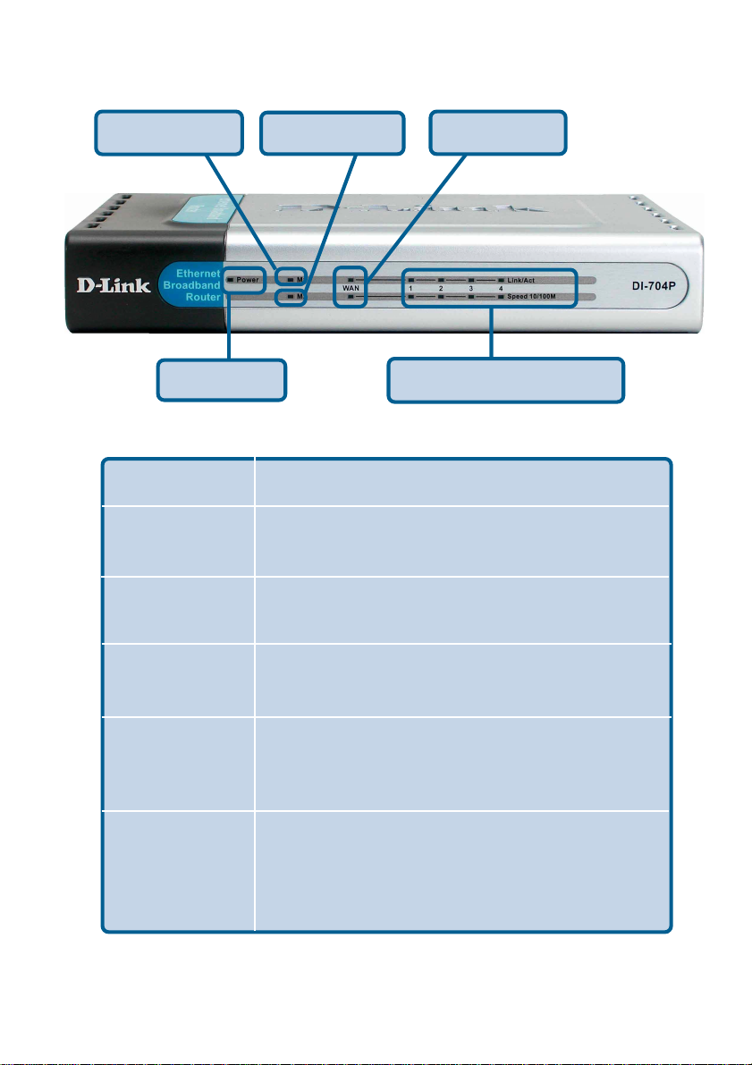
LEDs
M1 LED
POWER LED
LED
Power
M1 LED
M2 LED
LOCAL NETWORK LEDs
WAN LED
LED Activity
A solid light indicates a proper connection to
the power supply .
Flashes consistently to indicate that the
DI-704P is working properly .
M2 LED
WAN
LOCAL
NETWORK
LEDs
(Ports 1-4)
Solid light indicates that Internet connection has been established.
A Solid light indicates connection on the
WAN port. This LED blinks during data
transmission.
A solid light indicates a connection to an
Ethernet-enabled computer on ports 1-4. This
LED blinks during data transmission
6
Page 7
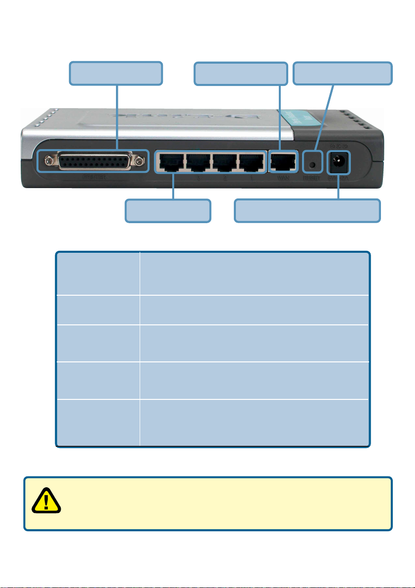
Connections
Printer Port
Receptor for
Power Adapter
Reset Button
Printer Port
WAN Port
LAN Ports
Connect the supplied power adapter that came
with the unit. Using the wrong power adapter will
damage the unit.
Reset button is to reset the device to its factory
default settings.
Connect to the printer using a parallel cable. This
feature is used to share the printer on the network.
Receptor for Power Adapter
Reset Button
WAN Port
Lan Ports
WARNING!
Using a power supply with a different voltage rating than the one
included with the DI-704P will cause damage and void the warranty
for this product.
WAN port is the connection point for your DSL or
Cable modem.
LAN port is where you would connect each
computer to your network.
7
Page 8

Introduction to Broadband Router Technology
A router is a device that forwards data packets from a source to a destination.
Routers can work on Open System Interconnection (OSI) layer 3, which forwards data packets using an IP address and not a MAC address. A router will
forward data from the Internet to a particular computer on your LAN.
The information that makes up the Internet gets moved around using routers.
When you click on a link on a wed page, you send a request to a server to show
you the next page. The information that is sent and received from your computer is moved from your computer to the server using routers. A router also
determines the best route that your information should follow to ensure that the
information is delivered properly .
A router controls the amount of data that is sent through your network by eliminating information that shouldn’t be there. This provides security for the computers behind your router because computers from the outside cannot access
or send information directly to any computer on your network. The router determines which computer the information should be forwarded to and sends it. If
the information is not intended for any computer on your network, the data is
discarded. This keeps any unwanted or harmful information from accessing or
damaging your network.
Introduction to Firewalls
A firewall is a device that sits between your computer and the Internet that prevents unauthorized access to or from your network. A firewall can be a computer using firewall software or a special piece of hardware built specifically to
act as a firewall. In most circumstances, a firewall is used to prevent unauthorized Internet users from accessing private networks suchs as corporate LANs
and Intranets.
A firewall watches all of the information moving to and from your network and
analyzes each piece of data. Each piece of data is checked against a set of
criteria that the administrator configures. If any data does not meet the criteria,
that data is blocked and discarded. If the data meets the criteria, the data is
paased through.. This method is called packet filtering.
A firewall can also run specific security functions based on the type of application or type of port that is being used. For example, a firewall can be configured
to work with an FTP or Telnet server. Or a firewall can be configured to work
with specific UDP or TCP ports to allow certain applications or games to work
properly over the Internet.
8
Page 9

Introduction to Local Area Networking
Local Area Networking (LAN) is the term used when connecting several computers together over a small area such as a building or group of buildings. LAN’s
can be connected over large areas. A collection of LANs connected over a large
area is called a Wide Area Network (W AN).
A LAN is consists of multiple computers connected to each other. There are
many types of media that can connect computers together. The most common
media is CA T5 cable; UTP or STP twisted p air wire. Each computer must have
a Network Interface Card (NIC), which communicates the data between computers. A NIC is usually a 10Mbps network card or 10/100Mbps network cards.
Most networks use hardware devices such as hubs or switches that each cable
can be connected to in order to continue the connection between computers. A
hub simply takes any data arriving through each port and forwards the data to
all other ports. A switch is more sophisticated, in that a switch can determine
the port that each piece of data is supposed to be delivered to. A switch minimizes network traffic and speeds up the communication over a network.
Networks take some time in order to plan and implement correctly. There are
many types of scenarios to consider which could affect the operability of a network. Some of these issues are discussed in the manual under the
Networking Basics section.
9
Page 10
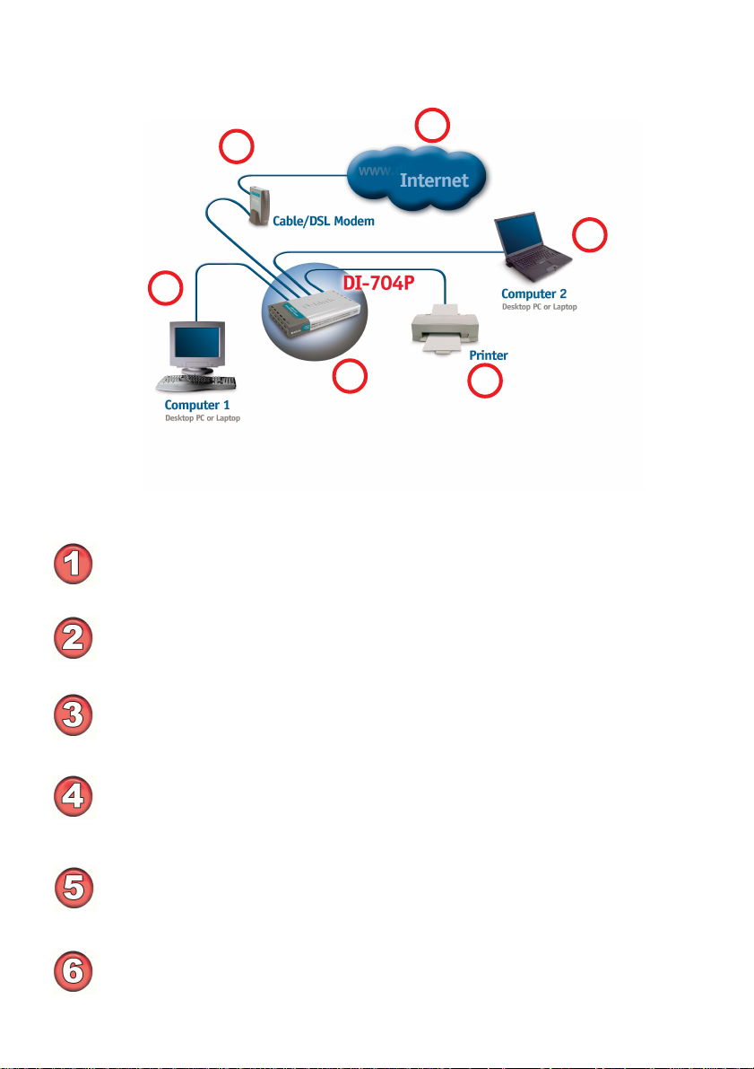
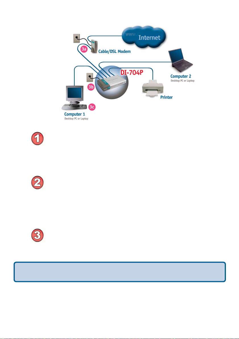
Sample Scenario
2
4
1
5
3
A typical network setup at home (as shown above) might contain the following de-
vices. For specific information on setting up your network with the DI-704P please see
the Network Setup section on the following page.
Y ou will need broadband Internet access (a Cable or DSL subscription line into
your home or office)
Consult with your Cable or DSL provider for proper installation of the modem
Connect the Cable or DSL modem to the DI-704P wireless broadband router
(see the Quick Installation Guide included with the DI-704P.)
If you are connecting a desktop computer to your network, you can install the
D-Link DFE-530TX+ Ethernet adapter into an available PCI slot. (See the
Quick Installation Guide included with the DWL-530TX+.)
If you are connecting a laptop computer to your network, install the drivers for
the Ethernet Cardbus adapter (e.g., D-Link DFE-690TXD) into a laptop
computer.(See the Quick Inst allation Guide included with the DFE-690TXD.)
6
Connect your printer to the printer port on the DI-704P. Please refer to the
quick installation guide for loading the print server software.
** Easily upgrade to a wireless network by adding a wireless Access Point (D-Link DWL-900AP+) **
10
Page 11
Network Setup
Turn everything off.
A. Power OFF your Cable or DSL modem. If you modem does
not have an on/off switch, disconnect the power cable.
B. Turn OFF your computer.
C. Do NOT connect the power adapter to your D-Link router.
Connect the D-Link Router Cables.
A. Connect the Ethernet (or networking) cable from the Cable or
DSL modem to the W AN port of the router.
B. Use the D-Link supplied Ethernet cable to connect the Ethernet
port (Network Card) of your computer to one of the LAN ports of
the router. The complete setup should look like Fig.1 shown above.
Power up the devices in sequence.
A. Power up the Cable or DSL modem. Wait until the modem has
made the connection to your Internet Service Prover’s (ISP’s)
network.
Note: Please see the Manual included with your modem for an explanation of
the modem’s LEDs.
B. Power up the D-Link router by connecting the D-Link provided
power adapter to the router and to an available power outlet.
C. Turn on your computer.
D. Now, refer to either the Quick Installation Guide or continue
to follow this manual to complete the installation process.
11
Page 12
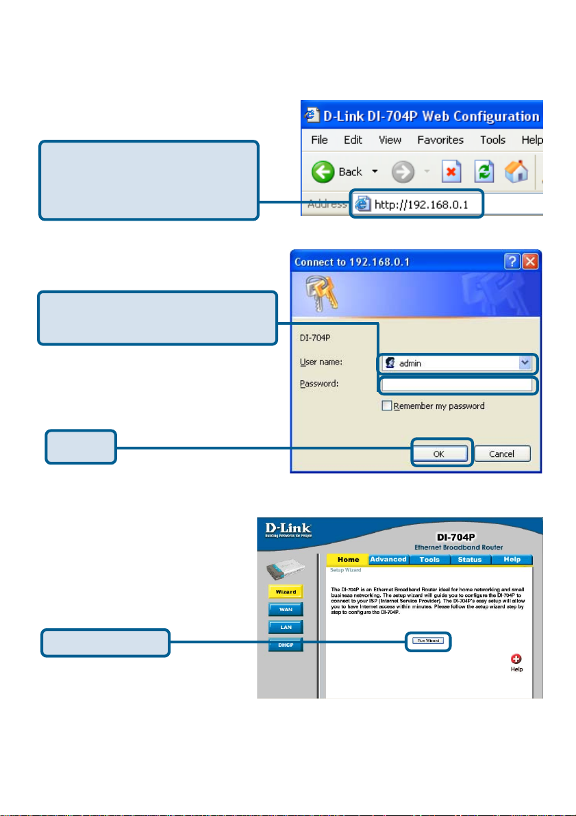
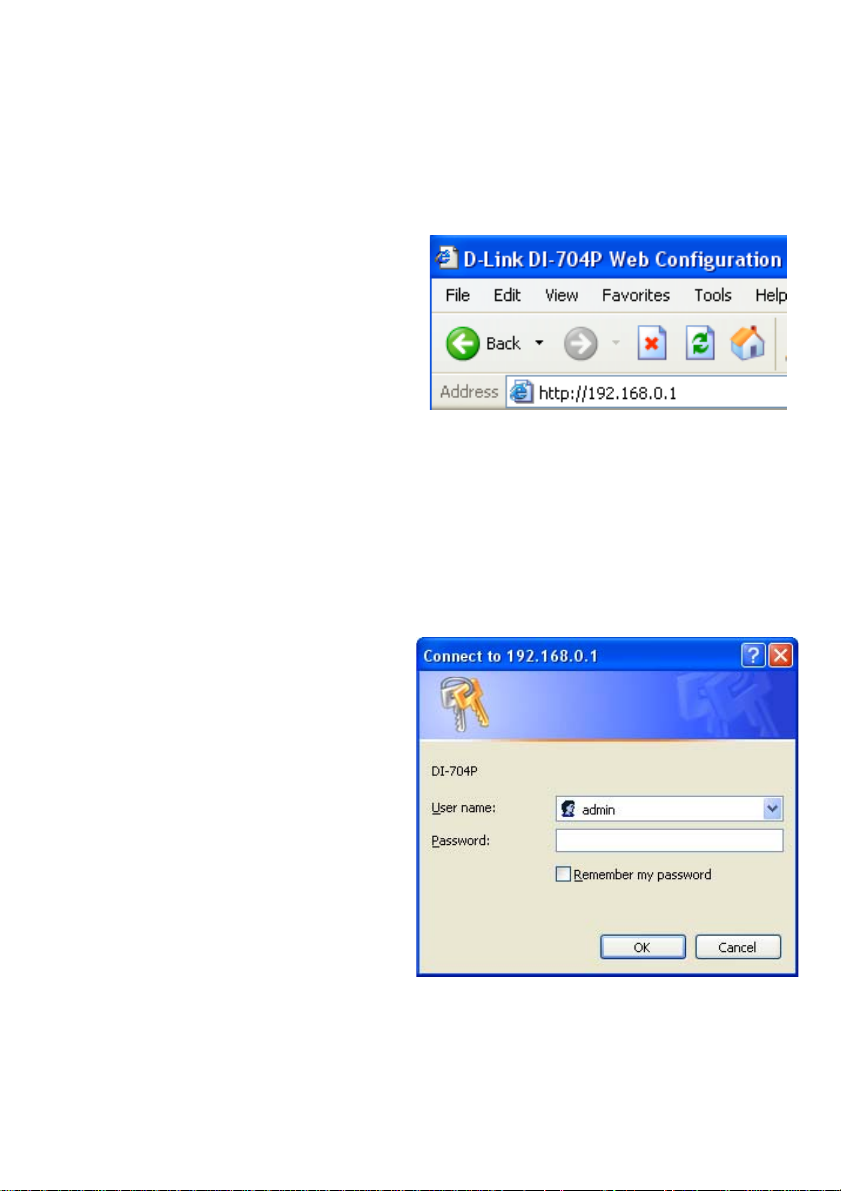
Using the Setup Wizard
Open your Web browser and
type “http://192.168.0.1” into the
URL address box. Then press the
Enter or Return key.
The logon pop-up screen will appear.
T ype “admin” for the username and
leave the password field blank.
Click OK
Once you have logged in, the Home
screen will appear.
Click Run Wizard
12
Page 13
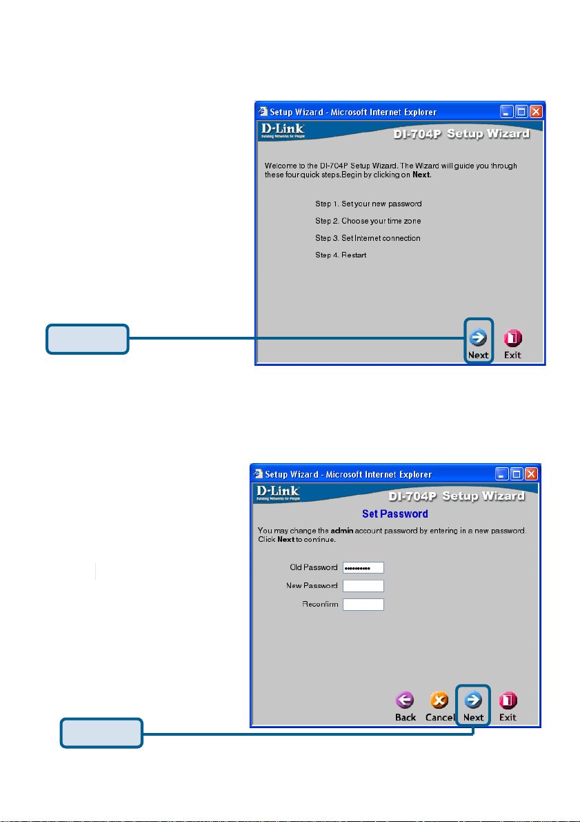
Using the Setup Wizard (continued)
Y ou will see the following screens
Click Next
Set up your new password.
Y ou have the option to
establish a password.
Click Next
13
Page 14
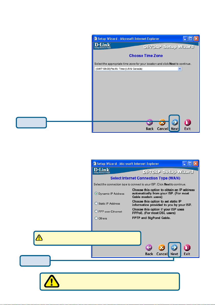
Using the Setup Wizard (continued)
Set up your Time Zone. You
have the option to the set
standard time for your router.
T o change the default
selection, select the drop
down arrow and chose the
correct time zone.
Click Next
Select your Internet
Connection. You will be
prompted to select the
type of Internet connection
for your router.
If you are unsure of which setting to select,
please contact your Internet Service Provider.
Click Next
Select Others only if you use PPTP in Europe or
BigPond Cable in Australia.
14
Page 15
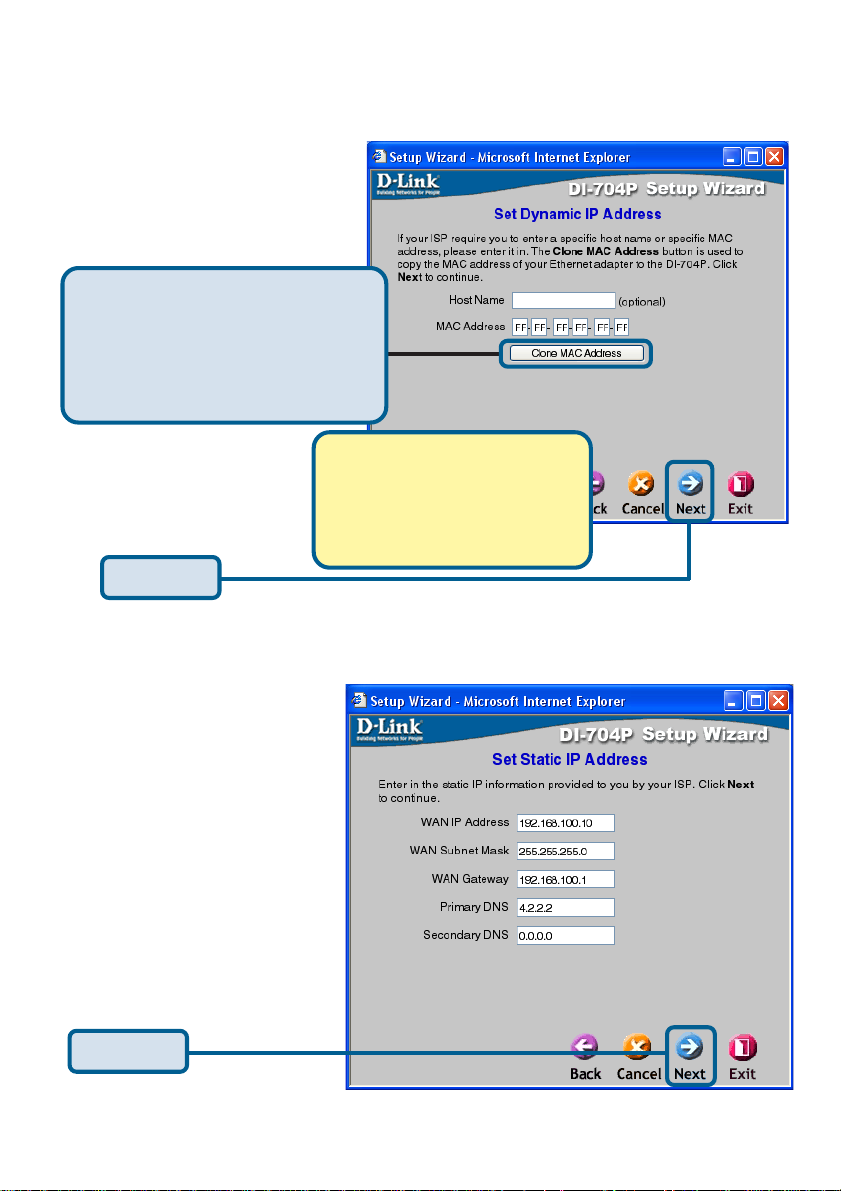
Using the Setup Wizard (continued)
If you selected Dynamic IP
Address, this screen will
appear: (Used mainly for
Cable Internet service.)
Click the “Clone MAC Address”
button to automatically copy the
MAC address of the network
adapter in your computer. Y ou can
also manually type in the MAC
address.
What is a MAC address? Each
network adapter has a discrete
Media Access Control (MAC)
address. Note that some computers
and peripherals may already
include built-in network adapters.
Click Next
If your ISP requires a Static
IP Address, and this option
is selected, then this
screen will appear:
Enter the IP Address information originally provided to you
by your ISP. You will need to
complete all the required
fields.
Click Next
15
Page 16
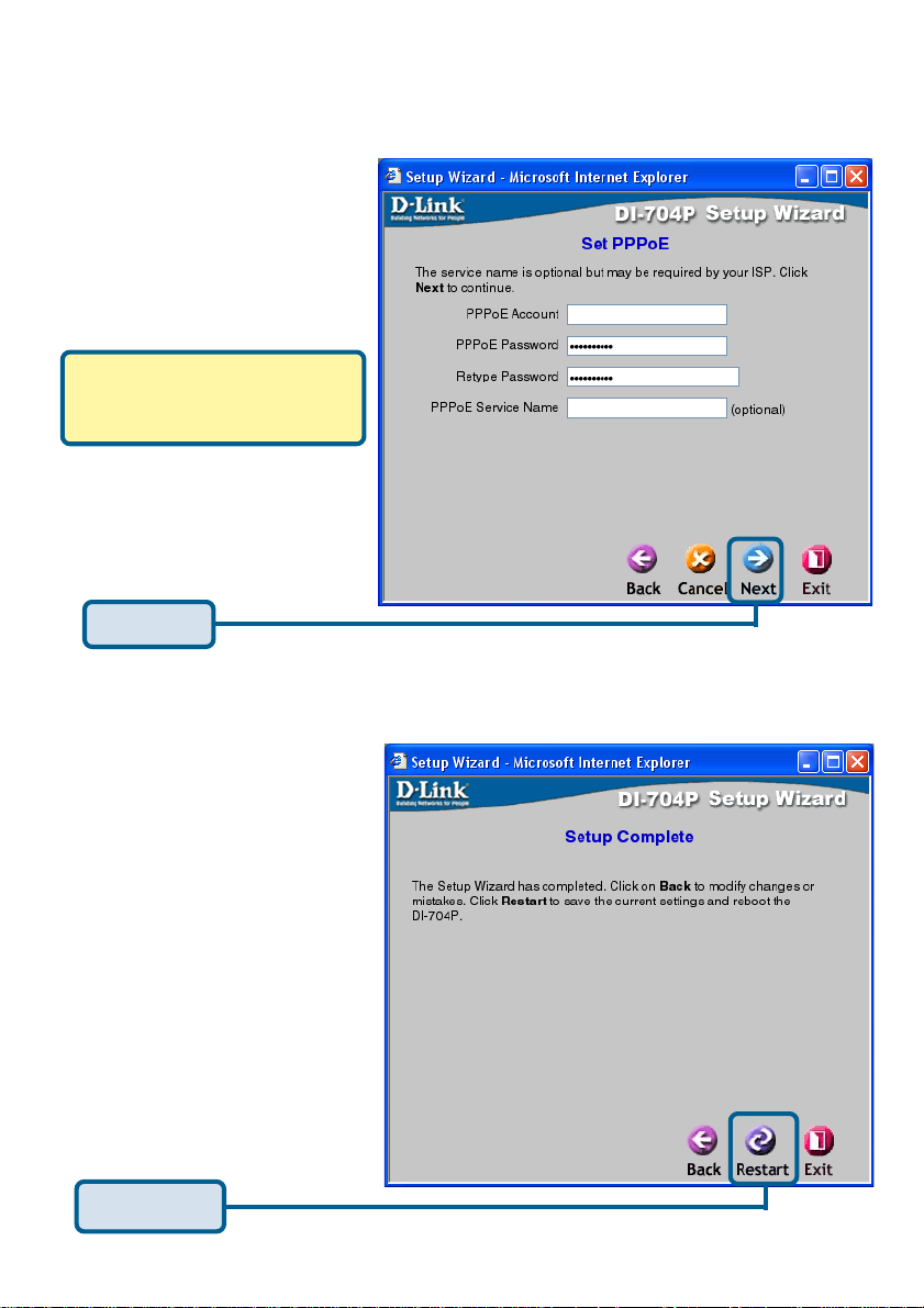
Using the Setup Wizard (continued)
If your ISP uses PPPoE
(Point-to-Point Protocol over
Ethernet), and this option is
selected, then this screen will
appear: (Used mainly for DSL
Internet service.)
Please be sure to remove any
existing PPPoE client software
installed on your computers.
Enter in the username and
password provided to you by
your ISP.
Click Next
Click Restart
16
Page 17
Using the Configuration Menu
Whenever you want to configure your network or the DI-704P, you can access the
Configuration Menu by opening the web-browser and typing in the IP Address of the DI-
704P . The DI-704P default IP Address is shown below:
Open the web browser
Type in the IP Address of
the DI-704P
Home > Wizard
Note: if you have changed the default IP Address assigned to the DI-704P, make sure to
enter the correct IP Address.
The factory default User name is
“admin” and the default Password is
blank (empty). It is recommended that
you change the admin password for
security purposes. Please refer to
Tools>Admin to change the admin
password.
17
Page 18
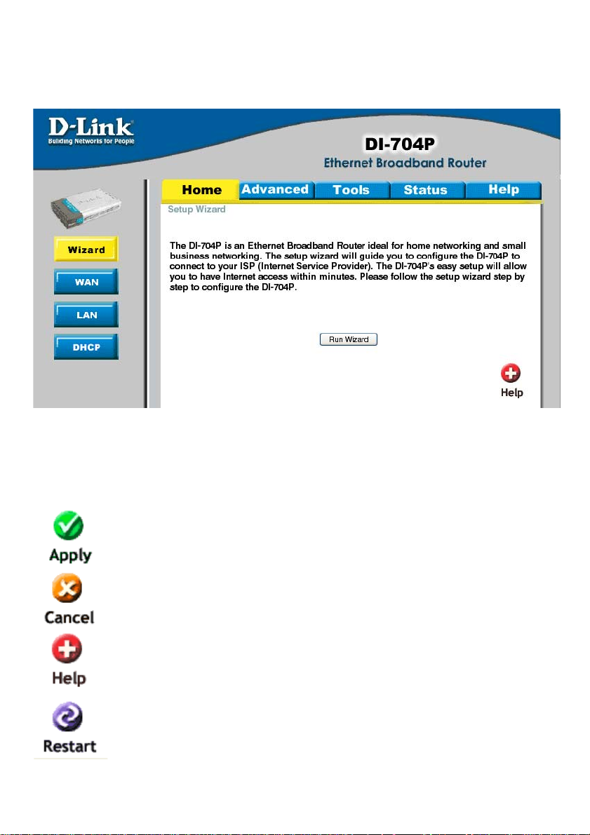
Using the Configuration Menu (continued)
Home > Wizard (continued)
The Home>Wizard screen will appear. Please refer to the Quick Installation Guide
for more information regarding the Setup Wizard.
Clicking Apply will save changes made to the page
Clicking Cancel will clear changes made to the page
Clicking Help will bring up helpful information regarding the page
Clicking Restart will restart the router . (Necessary for some changes.)
18
Page 19

Using the Configuration Menu (continued)
Home > WAN (continued)
WAN is short for Wide Area Network. The WAN settings can be referred to as the
Public settings. All IP information in the W AN settings are public IP addresses which
are accessible on the Internet. The WAN settings consist of four options: Dynamic IP
Address, Static IP
Address, PPPoE, and Others. Select the appropriate option and fill in the information
needed to connect to your ISP.
Choose Dynamic IP Address to obtain IP address information automatically from
your ISP. Select this option if your ISP does not give you any IP numbers to use. This
option is commonly used for Cable modem services. Host Name: The Host Name field
is optional but may be required by some ISPs. The host name is the device name of
the Broadband Router.
19
Page 20

Using the Configuration Menu (continued)
Home > W AN (continued)
MAC Address:
The default MAC address is set to the WAN’s physical interface MAC address on the
Broadband Router. You can use the “Clone MAC Address” button to copy the MAC
address of the Ethernet Card installed by your ISP and replace the WAN MAC
address with this MAC address. It is not recommended that you change the default
MAC address unless required by your ISP.
Primary/Secondary DNS Address:
Enter a DNS Address if you do not wish to use the one provided by your ISP.
MTU:
Only enter the MTU if it is required by your ISP. Otherwise, leave it
at the default setting of 1500.
Auto-reconnect:
If enabled, the Broadband Router will automatically connect to your ISP after your
system is restarted or if the connection is dropped.
20
Page 21
Using the Configuration Menu (continued)
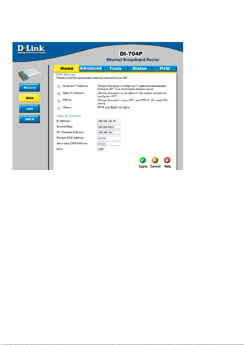
Home > W AN > St atic IP Address
Choose Static IP Address if all W AN IP information is provided to you by your ISP.
Y ou will need to enter in the IP Address, subnet mask, gateway address, and DNS
address(es) provided to you by your ISP. Each IP address entered in the fields must
be in the appropriate IP form, which are four IP octets separated by a dot (x.x.x.x).
The Router will not accept the IP Address if it is not in this format.
IP Address:
Public IP address provided by your ISP.
Subnet Mask:
Subnet mask provided by your ISP .
ISP Gateway Address:
Public IP address of your ISP that you are connecting to.
Primary/Secondary DNS Address:
Enter a DNS Address if you do not wish to use the one provided by your ISP.
MTU:
Enter an MTU value only if required by your ISP . Otherwise, leave it at the default
setting of 1500.
21
Page 22
Using the Configuration Menu (continued)
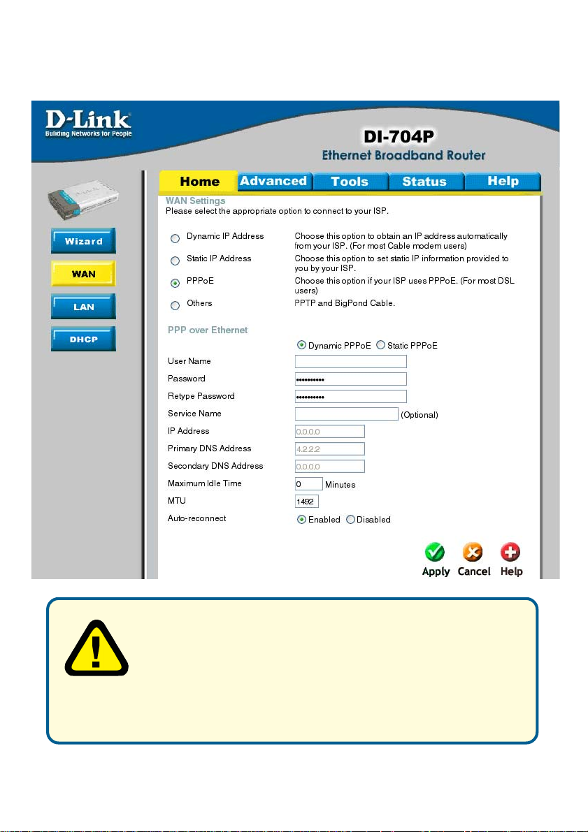
Home > WAN > PPPoE
Please be sure to remove any Client Software program on your
computer before you start your configuration of the DI-704P
Router. Choose PPPoE (Point to Point Protocol over Ethernet)
if your ISP uses PPPoE connection. Your ISP will provide you
with a username and password. This option is typically used for
DSL services. Select Dynamic PPPoE to obtain an IP address automatically
for your PPPoE connection. Select St atic PPPoE to use a static IP address
for your PPPoE connection.
22
Page 23

Using the Configuration Menu (continued)
Home > WAN > PPPoE (continued)
Dynamic PPPoE:
PPPoE connection where you will receive an IP address automatically from your ISP
Static PPPoE:
PPPoE connection where you have an assigned (static) IP address
User Name:
Y our PPPoE username provided by your ISP
Password:
Y our PPPoE password provided by your ISP
Retype Password:
Re-enter PPPoE password
Service Name:
Enter the service name provided by your ISP . (optional)
IP Address:
This option is only available for Static PPPoE. Enter in the st atic IP address for the
PPPoE connection.
Primary DNS Address:
Primary DNS IP provided by your ISP
Secondary DNS Address:
Optional
Maximum Idle time:
The amount of time of inactivity before disconnecting your PPPoE session. Enter a
Maximum Idle Time (in minutes) to define a maximum period of time for which the
Internet connection is maintained during inactivity . If the connection is inactive for
longer than the defined Maximum Idle Time, then the connection will be dropped.
Either set this to zero or enable Auto-reconnect to disable this feature.
MTU:
MTU stands for Maximum Transmission Unit. For PPPoE connections, you may need
to change the MTU settings in order to work correctly with your ISP.
Auto-reconnect:
If enabled, the Broadband Router will automatically connect to your ISP after your
system is restarted or if the connection is dropped.
23
Page 24
Using the Configuration Menu (continued)
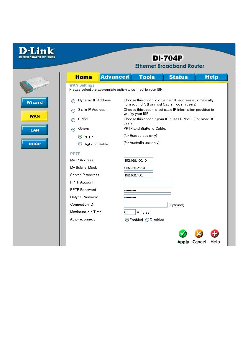
Home > W AN > PPTP
Dynamic IP Address for PPTP is a W AN connection used in Europe.
My IP Address:
Enter in the IP address for the
My Subnet Mask:
Enter the subnet mask information.
Server IP:
Enter the Server IP address. By default, its set to 192.168.0.1
24
Page 25

Using the Configuration Menu (continued)
Home > WAN > PPTP (continued)
PPTP Account:
Enter in the username for the PPTP account
PPTP Password:
Enter the password for the PPTP account. Retype in Password to confirm
Connection ID:
(Optional) enter the Connection ID if required
Maximum Idle Time:
The amount of time of inactivity before disconnecting your PPPoE session. Enter a
Maximum Idle Time (in minutes) to define a maximum period of time for which the
Internet connection is maintained during inactivity . If the connection is inactive for longer
than the defined Maximum Idle Time, then the connection will be dropped. Either set
this to zero or enable Auto-reconnect to disable this feature.
Auto-reconnect:
If enabled, the device will automatically connect to your ISP after your unit is restarted
or when the connection is dropped.
25
Page 26
Using the Configuration Menu (continued)
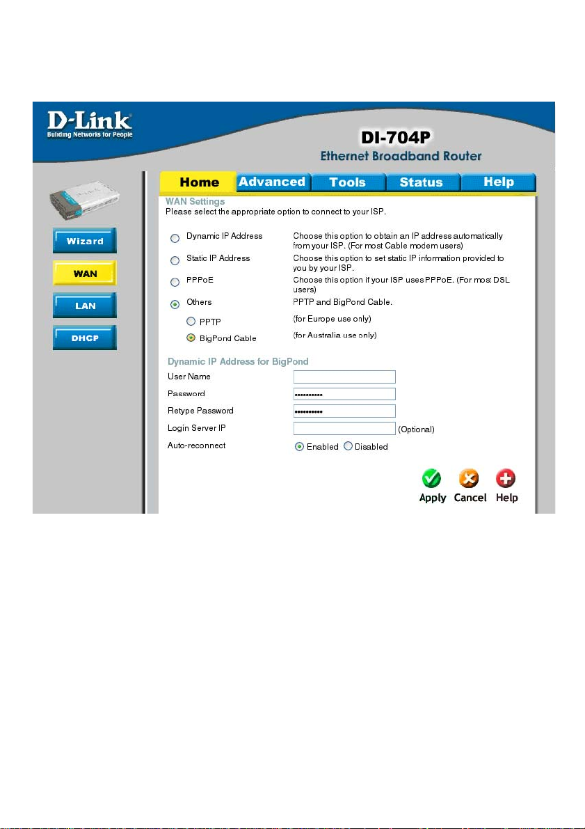
Home > WAN > BigPond Cable
Dynamic IP Address for BigPond is a W AN connection used in Australia.
Account:
Enter in the username for the BigPond account
Password:
Enter the password for the BigPond account
Login Server:
(Optional) enter the Login Server name if required
Auto-reconnect:
If enabled, the device will automatically connect to your ISP after your unit is restarted or when the connection is dropped.
26
Page 27
Using the Configuration Menu (continued)
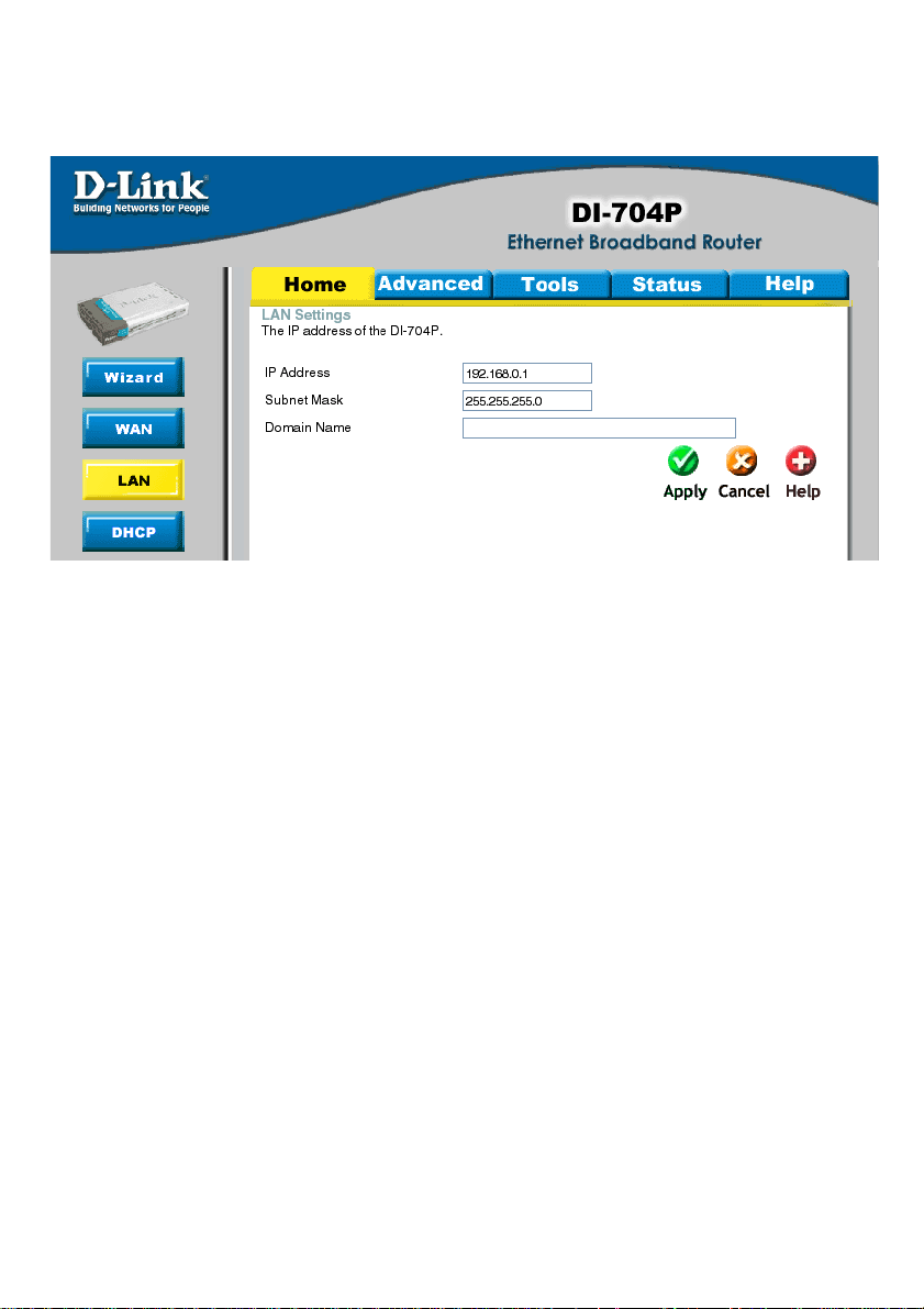
Home > LAN
LAN is short for Local Area Network. This is considered your internal network. These
are the IP settings of the LAN interface for the DI-704P. These settings may be
referred to as Private settings. Y ou may change the LAN IP address if needed. The
LAN IP address is private to your internal network and cannot be seen on the Internet.
IP Address:
The IP address of the LAN interface. The default IP address is
192.168.0.1.
Subnet Mask:
The subnet mask of the LAN interface. The default subnet
mask is 255.255.255.0.
Local Domain Name:
This field is optional. Enter in the your local domain name.
27
Page 28
Using the Configuration Menu (continued)
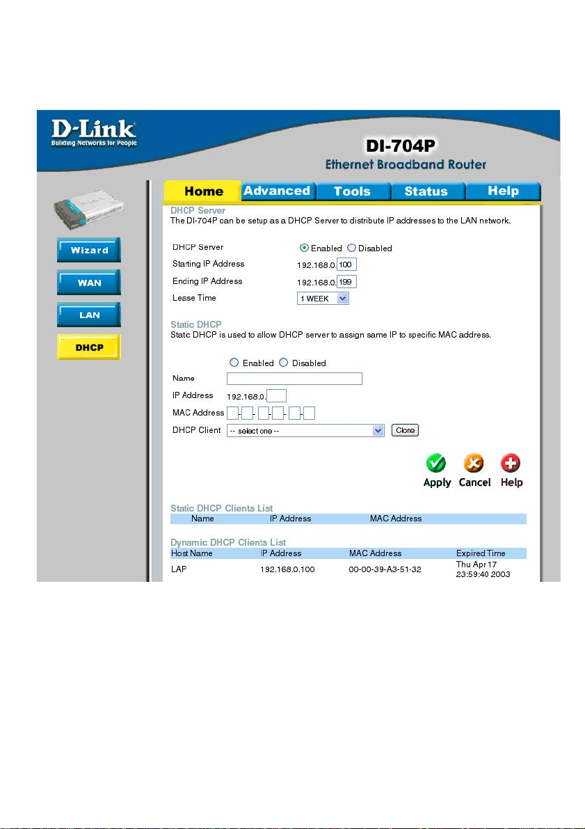
Home > DHCP
DHCP stands for Dynamic Host Control Protocol. The DI-704P has a built-in DHCP
server. The DHCP Server will automatically assign an IP address to the computers on
the LAN/private network. Be sure to set your computers to be DHCP clients by setting
their TCP/IP settings to “Obtain an IP Address Automatically.” When you turn your
computers on, they will automatically load the proper TCP/IP settings provided by the
DI-704P . The DHCP Server will automatically allocate an unused IP address from the
IP address pool to the requesting computer . You must specify the starting and ending
address of the IP address pool.
28
Page 29

Using the Configuration Menu (continued)
Home > DHCP
Static DHCP allows computers on the LAN to receive the same DHCP IP address
everytime it boots up. You can bind a specific IP address to a specific computer
based on the computer’s MAC address
Starting IP address:
The starting IP address for the DHCP server’s IP assignment.
Ending IP address:
The ending IP address for the DHCP server’s IP assignment.
Lease Time:
The length of time for the IP lease.
29
Page 30

Using the Configuration Menu (continued)
Advanced > Virtual Server
The DI-704P can be configured as a virtual server so that remote users accessing
Web or FTP services via the public IP address can be automatically redirected to
local servers in the LAN (Local Area Network). The DI-704P firewall feature filters out
unrecognized packets to protect your LAN network so all computers networked with
the DI-704P are invisible to the outside world. If you wish, you can make some of the
LAN computers accessible from the Internet by enabling Virtual Server. Depending on
the requested service, the DI-704P edirects the external service request to the
appropriate server within the LAN network.
30
Page 31

Using the Configuration Menu (continued)
Advanced > Virtual Server
The DI-704P is also capable of port-redirection meaning incoming traffic to a particular
port may be redirected to a different port on the server computer . Each virtual services
that are created will be listed at the bottom of the screen in the Virtual Servers List.
There are already pre-defined virtual services already in the table. Y ou may use them
by enabling them and assigning the server IP to use that particular virtual service.
Name:
The name referencing the virtual service.
Private IP:
The server computer in the LAN (Local Area Network) that will be providing the virtual
services.
Private Port:
The port number of the service used by the Private IP computer .
Protocol Type:
The protocol used for the virtual service.
Public Port:
The port number on the WAN side that will be used to access the virtual service.
Schedule:
The schedule of time when the virtual service will be enabled. The schedule may be
set to Always, which will allow the p articular service to always be enabled. If it is set
to Time, select the time frame for the service to be enabled. If the system time is
outside of the scheduled time, the service will be disabled.
Example #1:
If you have a Web server that you wanted Internet users to access at all times, you
would need to enable it. Web (HTTP) server is on LAN (Local Area Network) computer
192.168.0.25. HTTP uses port 80, TCP.
Name: Web Server
Private IP: 192.168.0.25
Protocol Type: TCP
Private Port: 80
Public Port: 80
Schedule: always
31
Page 32

Using the Configuration Menu (continued)
Advanced > Virtual Server
Example #2:
If you have an FTP server that you wanted Internet users to access by WAN port 2100
and only during the weekends, you would need to enable it as such. FTP server is on
LAN computer 192.168.0.30. FTP uses port 21, TCP.
Name: FTP Server
Private IP: 192.168.0.30
Protocol Type: TCP
Private Port: 21
Public Port: 2100
Schedule: From: 01:00AM to 01:00AM, Sat to Sun
• All Internet users who want to access this FTP Server must connect to it from port
2100. This is an example of port redirection and can be useful in cases where there
are many of the same servers on the LAN network.
32
Page 33

Using the Configuration Menu (continued)
Advanced > Application
Some applications require multiple connections, such as Internet gaming, video
conferencing, Internet telephony and others. These applications have difficulties working
through NA T (Network Address Translation). Special Applications makes some of these
applications work with the DI-704P. If you need to run applications that require multiple
connections, specify the port normally associated with an application in the Trigger
field, then enter the public ports associated with the trigger port into the Incoming
Ports field.
33
Page 34

Using the Configuration Menu (continued)
Advanced > Application
At the bottom of the screen, there are already defined special applications. To use
them, select one from the drop down list and select an ID number you want to use.
Then click the “Copy to” button and the router will fill in the appropriate information to
the list. Y ou will then need to enable the service. If the mechanism of Special Applications fails to make an application work, try using DMZ host instead.
Note! Only one PC can use each Special Application tunnel.
Enable / Disable:
Select to activate the policy . T o disable the virtual server feature, select disable.
Trigger Port:
This is the port used to trigger the application. It can be either a single port or a range
of ports.
Trigger Type:
Select the trigger protocol you would like to initiate. To chage the selection, use the
drop down arrow and other choices will be listed.
Public Ports:
Enter in the public port or ports to be used. A range of ports can be specified with a
hyphen.
Public Type:
Enter in the protocol type for public ports to access. To chage the selection, use the
drop down arrow and other choices will be listed.
Special Application List:
In the Special Application List, it will list some of the popular services with its trigger
ports. This is the port number on the WAN side that will be used to access the application.
Y ou may define a single port or a range of ports. Y ou can use a comma to add multiple
ports or port ranges.
34
Page 35

Using the Configuration Menu (continued)
Advanced > IP Filter
Use IP (Internet Protocol) filters to allow or deny computers access to the Internet based
on their IP address.
35
Page 36

Using the Configuration Menu (continued)
Advanced > IP Filter
Enabled or Disabled:
Click Enabled to apply the filter policy or click Disabled to enter an inactive filter policy
(Y ou can reactivate the policy later.)
IP Address:
Enter in the IP address range of the computers that you want the policy to apply to. If it
is only a single computer that you want the policy applied to, then enter the IP address of
that computer in the Start Source IP and leave the End Source IP blank.
Port Ranges:
Enter in the port range of the TCP/UDP ports that you want the policy to apply to. If it is
only a single port that you want the policy applied to, then enter the port number in the
Start Port field and leave the End Port field blank. If you want to use all the port s, you can
leave the port range empty .
Protocol:
Select the protocol type to allow or disallow certain to certain IP addresses.
Schedule:
Select Always, or choose From and enter the time period during which the IP filter policy
will be in effect.
36
Page 37

Using the Configuration Menu (continued)
Advanced > MAC Filters
MAC (Media Access Control) Filters are used to deny or allow LAN (Local Area Network)
computers from accessing the Internet and network by their MAC address.
At the bottom of the screen, there is a list of MAC addresses from the DHCP client
computers connected to the DI-704P. T o use them, select one from the drop down list
and select an IP number you want to use. Then click the “Copy to” button and the DI704P will fill in the appropriate information to the list.
37
Page 38

Using the Configuration Menu (continued)
Advanced > MAC Filters
Disabled MAC Filter:
Select this option if you do not want to use MAC filters on your Local Area Network
(LAN).
Only allow computers with MAC address listed below to access the
network:
Select this option to allow only computers that are in the list access to the network
and Internet. All other computers will be denied access to the network and Internet.
Only deny computers with MAC address listed below to access the
network:
Select this option to deny only computers that are in the list access to the network
and Internet. All other computers will be allowed access to the network and Internet.
Name:
Enter the Name to create a profile for the associated computer(s) on the network.
MAC Address:
Enter the MAC Address of the client that will be filtered.
DHCP Client:
Select from the DHCP Client list and click the Clone button to automatically clone that
computer’s MAC address to the MAC address field.
38
Page 39

Using the Configuration Menu (continued)
Advanced > URL Blocking
Use URL Blocking filters to disallow computer(s) to access Internet with the following
URL keywords entered into the list. The URL Blocking filters are useful feature and
similar to parental control. Users can enter keywords that may have adult content,
hack, or other materials to prevent computers connected to the Local Area Network
(LAN) from accessing those web sites.
39
Page 40

Using the Configuration Menu (continued)
Advanced > Domain Filter
Use Domain filters to allow or deny computers access to specific Internet domains
whether it is through www, ftp, snmp, etc. Domain filters apply to wired computers
connected to one of the four Ethernet LAN ports to the DI-704P.
40
Page 41

Using the Configuration Menu (continued)
Advanced > Domain Filter
Disabled Domain Filter:
Select this option if you do not want to use Domain filters.
Allow users to access the following domains and block all other domains:
Select this option to allow users to access the specified Internet domains listed
below. Users will be denied access to all other Internet domains.
Deny users to access the following domains and permit all other domains:
Select this option to deny users to access the specified Internet domains listed
below. Users will be allowed access to all other Internet domains.
Permitted Domains:
Enter in the domain suffix of the Internet domain you want to use.
(example: shopping.com, sports.net).
Blocked Domains:
Enter in the domain suffix of the Internet domain you want to block. (example:
shopping.com, sports.net).
Delete:
Select this option to remove the domain suffix from the Permitted Domains or Blocked
Domains list.
41
Page 42

Using the Configuration Menu (continued)
Advanced > Firewall
Firewall Rules is an advance feature used to deny or allow traffic from passing through
the Broadband Router. It works in the same way as IP Filters with additional settings.
Y ou can create more detailed access rules for the DI-704P. When virtual services are
created and enabled, it will also display in Firewall Rules. Firewall Rules contains all
network firewall rules pertaining to IP (Internet Protocol).
In the Firewall Rules List at the bottom of the screen, the priorities of the rules are
from top (highest priority) to bottom (lowest priority .)
Note: The DI-704P MAC Address filtering rules have precedence over the
Firewall Rules.
42
Page 43

Using the Configuration Menu (continued)
Advanced > SNMP
SNMP (Simple Network Management Protocol) is a widely used network monitoring and
control protocol that reports activity on each network device to the administrator of the
network. SNMP can be used to monitor traffic and statistics of the DI-704P. The DI704P supports SNMP v1.
Enabled or Disabled:
Click Enabled to enable SNMP click Disabled to deactivate SNMP.
Local:
SNMP services will be available on the Local (LAN) network.
Remote:
SNMP services will be available on the remote (WAN) network.
Get Community:
“Read only” access for network administration using SNMP . Y ou can view the network,
but no configuration is possible wth this setting.
Set Community:
“Read and Write” access for network administration using SNMP . The administrator can
configure the network with this setting.
43
Page 44

Using the Configuration Menu (continued)
Advanced > DDNS
DDNS (Dynamic Domain Name System) keeps dynamic IP addresses (e.g., IP
addresses assigned by a DHCP capable router or server) linked to a domain name.
Users who have a Dynamic DNS account may use this feature on the DI-704P.
DDNS:
When an IP address is automatically assigned by a DHCP server , DDNS automatically
updates the DNS server.
Provider:
Select from the pull-down menu.
Host Name:
Enter the Host name.
Username/Email:
Enter the username/email address.
Password/Key:
Enter the password/key .
44
Page 45
Using the Configuration Menu (continued)
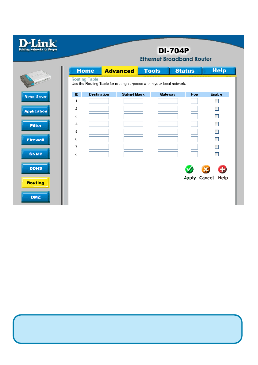
Advanced > Routing
Static routes can be added if you require specific routes within your internal network.
These routes will not apply to the WAN (Internet) network.
Destination:
Enter in the IP of the specified network that you want to access using the static route.
Subnet Mask:
Enter in the subnet mask to be used for the specified network.
Gateway:
Enter in the gateway IP address to the specified network.
Hop:
Enter in the amount of hops it will take to the specified network.
Enable:
Select this option for the specified static route to take effect.
Hop Count - in a transmission path, each link is terminated at a network device
such as a router or gateway. The number of hop s equals the number of routers or
gateways that data must pass through before reaching the destination.
45
Page 46

Using the Configuration Menu (continued)
Advanced > DMZ
If you have a computer that cannot run Internet applications properly from behind the
DI-704P , then you can allow that computer to have unrestricted Internet access. Enable
this feature and enter the IP address of that computer as a DMZ (Demilitarized Zone)
host with unrestricted Internet access. Adding a client to the DMZ may expose that
computer to a variety of security risks; so only use this option as a last resort.
46
Page 47

Using the Configuration Menu (continued)
T ools > Admin
Admininstrator Settings
At this page, the DI-704P administrator can change the system password. There are
two accounts that can access the Broadband Router’s Web-Management interface.
They are admin and user. Admin has read/write access while user has read-only
access. User can only view the settings but cannot make any changes.
47
Page 48

Using the Configuration Menu (continued)
T ools > Admin
Remote Management
Remote Management allows the DI-614+ to be configured from the Internet by a web
browser. A username and password is still required to access the W eb-Management
interface. In general, only a member of your network can browse the built-in web
pages to perform “Administrator” tasks. This feature enables you to perform
“Administrator” tasks from the remote (Internet) host.
IP Address:
Internet IP address of the computer that has access to the Broadband Router . It is
not recommended that you set the IP address to 0.0.0.0, because this allows any
Internet IP address to access the Broadband Router , which could result in a loss
of security for your network. If you elect to enable Remote Management, enter the
IP Address
of your remote location.
Port:
Select the port number used to access the Broadband Router.
Example: http://x.x.x.x:8080 whereas x.x.x.x is the WAN IP address of the
Broadband Router and 8080 is the port used for the Web-Management interface.
T ools > T ime
The system time is the time used by the DI-704P for scheduling services. You can
manually set the time or connect to a NTP (Network T ime Protocol) server . If an NTP
server is set, you will only need to set the time zone.
48
Page 49

Using the Configuration Menu (continued)
T ools > System
The current system settings can be saved as a file onto the local hard drive. The saved
file or any other saved setting file created by the DI-704P can be uploaded into the unit.
To reload a system settings file, click on Browse to search the local hard drive for the
file to be used. The device can also be reset back to factory default settings by clicking
on the Reset to Default button. Use the restore feature only if necessary. This will erase
previously saved settings for the unit. Make sure to save your system settings to the
hard drive before doing a factory restore.
Save Settings to Local Hard Drive:
Click Save to save the current settings to the local Hard Drive
Load Settings from Local Hard Drive:
Click Browse to find the settings file, then click Load
Restore to Factory Default Settings:
Click Reset to Default to restore the factory default
settings
49
Page 50

Using the Configuration Menu (continued)
T ools > Firmware
Y ou can upgrade the firmware by using this tool. First, check the D-Link support site for
firmware updates at http://support.dlink.com. Make sure that the firmware you want to
use is
saved on the local hard drive of your computer. Click on Browse to search the local hard
drive for the firmware that you downloaded from the D-Link website to be used for the
update. Upgrading the firmware will not change any of your system settings but it is
recommended that you save your system settings before doing a firmware upgrade.
Browse:
After you have downloaded the new firmware, click Browse in this window to locate the
firmware update on your hard drive. Click Apply to complete the firmware upgrade.
Note! Do not power off the unit when it is being upgraded. When the
upgrade is complete, the unit will be restarted automatically .
50
Page 51

Using the Configuration Menu (continued)
T ools > Misc
51
Page 52

Using the Configuration Menu (continued)
T ools > Misc
Ping Test:
This useful diagnostic utility can be used to check if a computer is on the Internet. It
sends ping packets and listens for replies from the specific host.
Reboot:
Click reboot to restart the unit.
Block WAN Ping:
Click Enable to block the WAN ping. Computers on the Internet will not get a reply back
from the DI-704P when it is being “ping”ed. This may help to increase security.
SPI Mode:
Stateful Packet Inspection is a form of firewall protection that will inspect all of the p ackets transmitted through the DI-704P. It carefully inspects all incoming packets and if it
packets contain suspecious information, it will automatically drop those packets.
UPnP Setting:
Universal Plug and Play is a feature that is preset to allow certain popular applications
such as MSN messenger to be functional using the router without making any configurations. By default UPnP setting is set to enable. It is recommended to keep UPnP Setting
on enable.
VPN Pass Through:
For users who telecommute or use Virtual Private Network (VPN), you can select PPTP
or IPSec to be used with this router.
Non-standard FTP port:
If an FTP server you want to access is not using the standard port 21, then enter in the
port number that the FTP server is using instead.
52
Page 53

Using the Configuration Menu (continued)
Status > Device Info
This page in the Configuration Utility displays the current information for the
Broadband Router. It will display the W AN, LAN, and MAC address information. If
your WAN connection is set up for Dynamic IP address a Release button and
Renew button will be displayed. Use Release to disconnect from your ISP and use
Renew to connect to your ISP. If your WAN connection is set up for PPPoE, a
Connect button and Disconnect button will be displayed. Use Disconnect to drop
the PPPoE connection and use Connect to establish the PPPoE connection. This
page allows you to observe the DI-704P’s working status:
53
Page 54

Using the Configuration Menu (continued)
Status > Device Info
LAN
LAN MAC Address:
Displays the LAN port MAC/hardware address
IP Address:
LAN/Private IP Address of the DI-704P
Subnet Mask:
LAN/Private Subnet Mask of the DI-704P
WAN
WAN MAC Address:
Displays the WAN port MAC/hardware address
IP Address:
WAN/Public IP Address
Subnet Mask:
WAN/Public Subnet Mask
Gateway:
WAN/Public Gateway IP Address
Domain Name Server:
WAN/Public DNS IP Address
PeripheralPrinter:
Status of the p arallel print server port.
54
Page 55

Using the Configuration Menu (continued)
Status > Log
The Broadband Router keeps a running log of events and activities occurring on the
Router. If the device is rebooted, the logs are automatically cleared. Y ou may save the
log files under Log Settings.
First Page:
The first page of the log.
Last Page:
The last page of the log.
Previous:
Moves back one log page.
Next:
Moves forward one log page.
Clear - Clears the logs completely.
Log Settings - Brings up the page to configure the logs.
55
Page 56

Using the Configuration Menu (continued)
Status > Log Settings
Log Settings
Not only does the Broadband Router display the logs of activities and events, it can
be setup to send these logs to another location.
E-Mail Alert:
The DI-704P can be set up to send the log files to a specific email address.
SMTP Server IP:
Input the SMTP information information. Usually , this is offered by your Internet service
provider (ISP).
Send E-Mail alert to:
Enter in the email address of the recipient who will receive the email log.
Send Mail Now:
Click to send mail immediately .
56
Page 57

Using the Configuration Menu (continued)
Help
Help
This menu displays the complete Help menu. For help at anytime, click on the Help
tab in the configuration menu.
57
Page 58

Inst alling the Print Server Software
Insert the installation CD-ROM into the CD-ROM drive. The following window will be
shown automatically . If it is not, please run “install.exe” on the CD-ROM.
Click Install Print
Server Software
Click Next
58
Page 59

Installing the Print Server Software (continued)
Select the destination folder.
Click Browse to
select a destination
folder
Click Next
Click Finish
Select the
option for
restarting the
computer.
Click OK
After rebooting your computer , the software installation procedure is finished.
59
Page 60

Configuring on Windows 98SE/ME Platforms
After you finish the software installation procedure, your computer will be capable of network
printing provided by the DI-704P . On a Windows
95/98 platform, open the Printers window in
the My Computer menu.
Now, you can configure the print server of
the DI-704P: Find out the corresponding
icon of your printer, for example, the HP
LaserJet 6L. Right click on that icon,
and then select Properties.
The screen at right appears.
Click on the
Details tab
Choose the “PRTmate: (All-in-1)” from
the list attached at the Print To item.
Be sure that the Printer Driver item is
Click Port Settings
60
Page 61

Configuring on Windows XP/2000/NT Platforms
Type in the IP address of the DI-704P .
Click OK
Click Port
The configuration procedure for a Windows
2000/XP platform is similar to that of Windows 95/98 except the screen of printer Prop-
erties:
Click Configure Port
Type in the IP address of the DI704P.
Click OK
(Note: Screen shots are taken in Windows 2000, similar
screens will appear in Windows XP.)
61
Page 62

Networking Basics
Using the Network Setup Wizard in Windows XP
In this section you will learn how to establish a network at home or work,
using Microsoft Windows XP.
Note: Please refer to websites such as
http://www.microsoft.com/windows2000 for information about
and
networking computers using Windows 2000, ME or 98SE.
Go to Start>Control Panel>Network Connections
Select Set up a home or small office network
http://www.homenethelp.com
When this screen appears, click Next.
62
Page 63

Networking Basics
Please follow all the instructions in this window:
Click Next
In the following window, select the best description of your computer. If your
computer connects to the internet through a gateway/router, select the
second option as shown.
Click Next
63
Page 64

Networking Basics
Enter a Computer description and a Computer name (optional.)
Click Next
Enter a Workgroup name. All computers on your network should have the
same Workgroup name.
Click Next
64
Page 65

Networking Basics
Please wait while the Network Setup Wizard applies the changes.
When the changes are complete, click Next.
Please wait while the Network Setup Wizard configures the computer.
This may take a few minutes.
65
Page 66

Networking Basics
In the window below, select the option that fit s your needs. In this example, Create
a Network Setup Disk has been selected. You will run this disk on each of the
computers on your network. Click Next.
Insert a disk into the Floppy Disk Drive, in this case drive A.
Format the disk if you wish, and click Next.
66
Page 67

Networking Basics
Please read the information under Here’s how in the screen below. After you complete the Network Setup Wizard you will use the Network Setup Disk to run the
Network Setup Wizard once on each of the computers on your network. To continue
click Next.
67
Page 68

Networking Basics
Please read the information on this screen, then click Finish to complete the
Network Setup Wizard.
The new settings will take effect when you restart the computer. Click Yes to
restart the computer.
You have completed configuring this computer. Next, you will need to run the
Network Setup Disk on all the other computers on your network. After running the Network Setup Disk on all your computers, your new wireless network will be ready to use.
68
Page 69

Networking Basics
Naming your Computer
To name your computer, please follow these directions:In Windows XP:
Click Start (in the lower left corner of the screen)
!
Right-click on My Computer
!
Select Properties and click
!
Select the Computer
!
Name Tab in the System
Properties window.
!
You may enter a Computer Description if you
wish; this field is optional.
To rename the computer
!
and join a domain, Click
Change.
69
Page 70

Networking Basics
Naming your Computer
!
In this window, enter the
Computer name
Select Workgroup and enter
!
the name of the Workgroup
All computers on your network
!
must have the same
Workgroup name.
Click OK
!
Checking the IP Address in Windows XP
The wireless adapter-equipped computers in your network must be in the same IP
Address range (see Getting Started in this manual for a definition of IP Address Range.)
To check on the IP Address of the adapter, please do the following:
Right-click on the
!
Local Area
Connection icon
in the task bar
Click on Status
!
70
Page 71

Networking Basics
Checking the IP Address in
This window will appear.
Click the
!
Support tab
Click Close
!
Windows XP
Assigning a Static IP Address in Windows XP/2000
Note: Residential Gateways/Broadband Routers will automatically assign IP Addresses to the computers on the network, using DHCP (Dynamic Host Configuration Protocol) technology. If you are using a DHCP-capable Gateway/Router you
will not need to assign Static IP Addresses.
If you are not using a DHCP capable Gateway/Router , or you need to assign a S tatic IP
Address, please follow these instructions:
Go to Start
!
Double-click on
!
Control Panel
71
Page 72

Networking Basics
Assigning a Static IP Address in
Double-click on
!
Network
Connections
Windows XP/2000
Right-click on Local Area
!
Connections
Double-click on
!
Properties
72
Page 73

Networking Basics
Assigning a Static IP Address
in Windows XP/2000
Click on Internet Protocol
!
(TCP/IP)
Click Properties
!
In the window below, select Use the following IP address. Input your IP
!
!
address and subnet mask. (The IP Addresses on your network must be
within the same range. For example, if one computer has an IP Address of
192.168.0.2, the other computers should have IP Addresses that are
sequential, like 192.168.0.3 and 192.168.0.4. The subnet mask must be
the same for all the computers on the network.)
IP Address:
e.g., 192.168.0.2
Subnet Mask:
255.255.255.0
Default Gateway:
Enter the LAN IP address of
the wireless router. (D-Link
wireless routers have a LAN IP
address of 192.168.0.1)
Select Use the following
!
DNS server address. Enter
the LAN IP address of the
Wireless Router. (D-Link
wireless routers have a LAN
IP address of 192.168.0.1)
!
Click OK
You have completed the assignment of a S tatic IP Address. (Y ou do not need to assign
a Static IP Address if you have a DHCP-capable Gateway/Router.)
73
Page 74

Networking Basics
Selecting a Dynamic IP Address with
Go to the Apple Menu and se-
!
lect System Preferences
!
Click on Network
!
Select Built-in Ethernet in
the Show pull-down menu
Select Using DHCP in the
!
Configure pull-down menu
Macintosh OSX
Click Apply Now
!
The IP Address, Subnet
!
mask, and the Router’s IP
Address will appear in a
few seconds
74
Page 75

Networking Basics
Checking the Wireless Connection by
Pinging in Windows XP and
2000
Go to Start > Run >
!
type cmd. A window
similar to this one
will appear. Type
ping
xxx.xxx.xxx.xxx,
where xxx is the IP
Address of the
Wireless Router or
Access Point. A
good wireless
connection will show
four replies from the
Wireless Router or
Acess Point, as
shown.
Checking the Wireless Connection by Pinging in Windows Me
and 98
Go to Start > Run
!
> type command.
A window similar to
this will appear.
Type ping
xxx.xxx.xxx.xxx
where xxx is the IP
Address of the
Wireless Router or
Access Point. A
good wireless
connection will
show four replies
from the wireless
router or access
point, as shown.
75
Page 76

Networking Basics
Adding and Sharing Printers in
After you have run the Network Setup Wizard on all the computers in your
network (please see the Network Setup Wizard section at the beginning of
Networking Basics,) you can use the Add Printer Wizard to add or share a
printer on your network.
Whether you want to add a local printer (a printer connected directly to one
computer,) share an LPR printer (a printer connected to a print server) or
share a network printer (a printer connected to your network through a
Gateway/Router,) use the Add Printer Wizard. Please follow the directions
below:
First, make sure that you have run the
the computers on your network.
On the following pages, we will show you these 3 ways to use the Add Printer
Wizard:
Windows XP
Network Setup Wizard on all of
1. Adding a local printer
2. Sharing an network printer
3. Sharing an LPR printer
(Other Networking Tasks)
For help with other tasks, that we have not covered here, in home or small
office networking, see Using the Shared Documents folder and Sharing
files and folders in the Help and Support Center in Microsoft Windows XP.
76
Page 77

Networking Basics
Adding a local printer (a printer connected directly to a computer)
A printer that is not shared on the network and is connected directly to one
computer is called a local printer. If you do not need to share your printer
on a network, follow these directions to add the printer to one computer.
Go to Start>
!
Printers and
Faxes
Click on Add a printer
!
77
Page 78

Networking Basics
Adding a local printer
!
Click Next
Select Local
!
printer attached to
this computer
(Deselect Automatically detect and
!
install my Plug and
Play printer if it has
been selected.)
Click Next
!
Select Use the
!
following port:
From the pull-down
!
menu select the
correct port for your
printer
(Most computers use the LPT1:
port, as shown in the illustration.)
Click Next
!
78
Page 79

Networking Basics
Adding a local printer
Select and highlight the
!
correct driver for your
printer.
!
Click Next
(If the correct driver is not
displayed, insert the CD or
floppy disk that came with your
printer and click Have Disk.)
At this screen, you
can change the
!
name of the printer
(optional.)
!
Click Next
!
Select Yes, to print a test
page. A successful
printing will confirm that
you have chosen the
correct driver.
Click Next
!
79
Page 80

Networking Basics
Adding a local printer
This screen gives you information about your printer.
Click Finish
When the test page has printed,
Click OK
80
Page 81

Networking Basics
Adding a local printer
Go to Start> Printers
!
and Faxes
A successful installation will display
the printer icon as shown at right.
You have successfully added a
local printer.
Sharing a network printer
After you have run the Network Setup Wizard on all the computers on your
network, you can run the Add Printer Wizard on all the computers on your
network. Please follow these directions to use the Add Printer Wizard to
share a printer on your network:
Go to Start> Printers
!
and Faxes
81
Page 82

Networking Basics
Sharing a network printer
Click on
!
Add a printer
!
Click Next
Select
!
Network Printer
Click Next
!
82
Page 83

Networking Basics
Sharing a network printer
Select Browse for a printer
!
Click Next
!
Select the printer you
would like to share
!
!
Click Next
Click Finish
83
Page 84

Networking Basics
Sharing a network printer
T o check for proper
!
installation:
Go to Start > Printers
!
and Faxes
The printer icon will appear at right,
indicating proper installation.
You have completed adding
the printer.
To share this printer on your
network:
Remember the
!
printer name
Run the Add Printer
!
Wizard on all the computers on your network
Make sure you have
already run the Network
!
Setup Wizard on all the
network computers
After you run the Add Printer
Wizard on all the computers in
the network, you can share the
printer.
84
Page 85

Networking Basics
Sharing an LPR printer
To share an LPR printer (using a print server,) you will need a Print Server
such as the DP-101P+. Please make sure that you have run the Network
Setup Wizard on all the computers on your network. To share an LPR
printer, please follow these directions:
Go to Start >
!
Printers and
Faxes
Click on
!
Add a
Printer
The screen to the right
will appear
Click Next
!
Select Local
!
Printer...
Click Next
!
85
Page 86

Networking Basics
Sharing an LPR printer
!
Select Create a new port
From the pull-down menu,
!
select Standard TCP/IP
Port, as shown.
!
Click Next
Please read the
!
instructions on this
screen
Click Next
!
Enter the Printer IP
!
Address and the Port
Name, as shown.
Click Next
!
86
Page 87

Networking Basics
Sharing an LPR printer
In this screen,
!
select Custom
Click Settings
!
Enter the
!
Port Name
and the
Printer
Name or
IP Address
!
Select LPR
Enter a Queue
!
Name (if your
Print-Server/
Gateway has
more than one
port, you will
need a Queue
name.)
Click OK
!
87
Page 88

Networking Basics
Sharing an LPR printer
!
This screen will show
you information about
your printer.
!
Click Finish
Select the printer you
!
are adding from the
list of Printers.
Insert the printer driver disk
!
that came with your printer.
Click Have Disk
!
If the printer driver is already installed, do the following:
Select Keep
!
existing driver
!
Click Next
88
Page 89

Networking Basics
Sharing an LPR printer
You can rename your printer
!
if you choose. It is optional.
Please remember the name
!
of your printer. Y ou will need
this information when you
use the Add Printer Wizard
on the other computers on
your network.
Click Next
!
Select Yes, to print a test
!
page.
Click Next
!
This screen will display information about your printer.
!
Click Finish to complete
the addition of the printer.
!
Please run the Add Printer
Wizard on all the comput-
ers on your network in
order to share the printer.
Note: Y ou must run the Network Setup Wizard on all the computers on your network
before you run the Add Printer Wizard.
89
Page 90

Resetting the DI-704P
to the Factory Default Settings
After you have tried other methods for troubleshooting your network, you
may choose to Reset the DI-704P to the factory default settings.
To hard-reset the D-Link DI-704P to the Factory Default Settings, please do
the following:
Turn off the DI-704P
!
Locate the Reset button on the back of the DI-704P
!
Use a paper clip to press the Reset button and
!
power on
Hold for about 5 seconds (don’t hold too long) and
!
then release. (Or, release when M1 and M2 flash
at the same time.)
! After you have completed the above steps, the DI-704P
will be reset to the factory default settings
90
Page 91

Technical Specifications
Standard
IEEE 802.3 10Base-T Ethernet
IEEE 802.3u 100Base-TX Fast Ethernet
IEEE 802.3 NWay Auto-Negotiation
VPN Pass Through
PPTP
L2TP
IPSec
Ports
One WAN
Four LAN
LEDs
Power
WAN
Local Network - 10/100
Operating T emperature
32oF to 131oF (0oC to 55oC)
Humidity
95% maximum (non-condensing)
Power
External Power Supply
DC 5V , 2A
Dimensions
L = 7.56 inches (192mm)
W = 4.64 inches (1 18mm)
H = 1.22 inches (31mm)
Weight
0.68 lbs (0.31kg)
Warranty
One Y ear
91
Page 92

T echnical Support
Y ou can find software updates and user documentation on the D-Link website.
D-Link provides free technical support for customers within the United St ates and
within Canada for the duration of the warranty period on this product.
U.S. and Canadian customers can contact D-Link technical support through our
website, or by phone.
Tech Support for customers within the United States:
D-Link Technical Support over the Telephone:
(877) 453-5465
24 hours a day, seven days a week.
D-Link Technical Support over the Internet:
http://support.dlink.com
email:support@dlink.com
Tech Support for customers within Canada:
D-Link Technical Support over the Telephone:
(800) 361-5265
Monday to Friday 8:30am to 9:00pm EST
D-Link Technical Support over the Internet:
http://support.dlink.ca
email:support@dlink.ca
92
Page 93

Warranty and Registration
(USA only)
Subject to the terms and conditions set forth herein, D-Link Systems, Inc. (“D-Link”) provides this Limited
warranty for its product only to the person or entity that originally purchased the product from:
• D-Link or its authorized reseller or distributor and
• Products purchased and delivered within the fifty states of the United S tates, the District of Columbia,
U.S. Possessions or Protectorates, U.S. Military Installations, addresses with an APO or FPO.
Limited Warranty: D-Link warrants that the hardware portion of the D-Link products described
below will be free from material defects in workmanship and materials from the date of original retail
purchase of the product, for the period set forth below applicable to the product type (“Warranty
Period”), except as otherwise stated herein.
1-Year Limited Warranty for the Product(s) is defined as follows:
• Hardware (excluding power supplies and fans) One (1) Year
• Power Supplies and Fans One (1) Year
• Spare parts and spare kits Ninety (90) days
D-Link’s sole obligation shall be to repair or replace the defective Hardware during the Warranty Period
at no charge to the original owner or to refund at D-Link’s sole discretion. Such repair or replacement will
be rendered by D-Link at an Authorized D-Link Service Office. The replacement Hardware need not be
new or have an identical make, model or part. D-Link may in its sole discretion replace the defective
Hardware (or any part thereof) with any reconditioned product that D-Link reasonably determines is
substantially equivalent (or superior) in all material respects to the defective Hardware. Repaired or
replacement Hardware will be warranted for the remainder of the original Warranty Period from the date
of original retail purchase. If a material defect is incapable of correction, or if D-Link determines in its sole
discretion that it is not practical to repair or replace the defective Hardware, the price paid by the original
purchaser for the defective Hardware will be refunded by D-Link upon return to D-Link of the defective
Hardware. All Hardware (or part thereof) that is replaced by D-Link, or for which the purchase price is
refunded, shall become the property of D-Link upon replacement or refund.
Limited Software Warranty: D-Link warrants that the software portion of the product (“Software”)
will substantially conform to D-Link’s then current functional specifications for the Software, as set forth
in the applicable documentation, from the date of original retail purchase of the Software for a period of
ninety (90) days (“Warranty Period”), provided that the Software is properly installed on approved
hardware and operated as contemplated in its documentation. D-Link further warrants that, during the
Warranty Period, the magnetic media on which D-Link delivers the Software will be free of physical
defects. D-Link’s sole obligation shall be to replace the non-conforming Software (or defective media)
with software that substantially conforms to D-Link’s functional specifications for the Software or to
refund at D-Link’s sole discretion. Except as otherwise agreed by D-Link in writing, the replacement
Software is provided only to the original licensee, and is subject to the terms and conditions of the
license granted by D-Link for the Software. Software will be warranted for the remainder of the original
Warranty Period from the date or original retail purchase. If a material non-conformance is incapable of
correction, or if D-Link determines in its sole discretion that it is not practical to replace the nonconforming Software, the price paid by the original licensee for the non-conforming Software will be
refunded by D-Link; provided that the non-conforming Software (and all copies thereof) is first returned
to D-Link. The license granted respecting any Software for which a refund is given automatically
terminates.
Non-Applicability of Warranty: The Limited Warranty provided hereunder for hardware and software
of D-Link’s products will not be applied to and does not cover any refurbished product and any product
purchased through the inventory clearance or liquidation sale or other sales in which D-Link, the sellers,
or the liquidators expressly disclaim their warranty obligation pertaining to the product and in that case,
the product is being sold “As-Is” without any warranty whatsoever including, without limitation, the
Limited Warranty as described herein, notwithstanding anything stated herein to the contrary.
Submitting A Claim: The customer shall return the product to the original purchase point based on its
return policy. In case the return policy period has expired and the product is within warranty, the
customer shall submit a claim to D-Link as outlined below:
93
Page 94

• The customer must submit with the product as part of the claim a written description of the Hardware
defect or Software nonconformance in sufficient detail to allow D-Link to confirm the same.
• The original product owner must obtain a Return Material Authorization (“RMA”) number from the
Authorized D-Link Service Office and, if requested, provide written proof of purchase of the
product (such as a copy of the dated purchase invoice for the product) before the warranty
service is provided.
• After an RMA number is issued, the defective product must be packaged securely in the original or
other suitable shipping package to ensure that it will not be damaged in transit, and the RMA number
must be prominently marked on the outside of the package. Do not include any manuals or accessories
in the shipping package. D-Link will only replace the defective portion of the Product and will not
ship back any accessories.
• The customer is responsible for all in-bound shipping charges to D-Link. No Cash on Delivery
(“COD”) is allowed. Products sent COD will either be rejected by D-Link or become the property of
D-Link. Products shall be fully insured by the customer. D-Link will not be held responsible for any
packages that are lost in transit to D-Link. The repaired or replaced packages will be shipped to the
customer via UPS Ground or any common carrier selected by D-Link, with shipping charges prepaid.
Expedited shipping is available if shipping charges are prepaid by the customer and upon request.
• Return Merchandise Ship-To Address
USA: 53 Discovery Drive, Irvine, CA 92618
Canada: 2180 Winston Park Drive, Oakville, ON, L6H 5W1 (Visit
warranty information within Canada)
D-Link may reject or return any product that is not packaged and shipped in strict compliance with the
foregoing requirements, or for which an RMA number is not visible from the outside of the package. The
product owner agrees to pay D-Link’s reasonable handling and return shipping charges for any product
that is not packaged and shipped in accordance with the foregoing requirements, or that is determined
by D-Link not to be defective or non-conforming.
What Is Not Covered: This limited warranty provided by D-Link does not cover: Products, if in D-Link’s
judgment, have been subjected to abuse, accident, alteration, modification, tampering, negligence, misuse,
faulty installation, lack of reasonable care, repair or service in any way that is not contemplated in the
documentation for the product, or if the model or serial number has been altered, tampered with, defaced
or removed; Initial installation, installation and removal of the product for repair, and shipping costs;
Operational adjustments covered in the operating manual for the product, and normal maintenance;
Damage that occurs in shipment, due to act of God, failures due to power surge, and cosmetic damage;
Any hardware, software, firmware or other products or services provided by anyone other than DLink; Products that have been purchased from inventory clearance or liquidation sales or other sales in
which D-Link, the sellers, or the liquidators expressly disclaim their warranty obligation pertaining to the
product. Repair by anyone other than D-Link or an Authorized D-Link Service Office will void this
Warranty.
Disclaimer of Other Warranties: EXCEPT FOR THE LIMITED WARRANTY SPECIFIED HEREIN, THE
PRODUCT IS PROVIDED “AS-IS” WITHOUT ANY W ARRANTY OF ANY KIND WHA TSOEVER INCLUDING ,
WITHOUT LIMIT A TION, ANY W ARRANTY OF MERCHANT ABILITY , FITNESS FOR A P ARTICULAR PURPOSE
AND NON-INFRINGEMENT . IF ANY IMPLIED WARRANTY CANNOT BE DISCLAIMED IN ANY TERRITORY
WHERE A PRODUCT IS SOLD, THE DURA TION OF SUCH IMPLIED W ARRANTY SHALL BE LIMITED TO
NINETY (90) DA YS. EXCEPT AS EXPRESSL Y COVERED UNDER THE LIMITED W ARRANTY PROVIDED
HEREIN, THE ENTIRE RISK AS TO THE QUALITY , SELECTION AND PERFORMANCE OF THE PRODUCT IS
WITH THE PURCHASER OF THE PRODUCT .
http://www.dlink.ca for detailed
94
Page 95

Limitation of Liability: TO THE MAXIMUM EXTENT PERMITTED BY LAW, D-LINK IS NOT LIABLE
UNDER ANY CONTRACT, NEGLIGENCE, STRICT LIABILITY OR OTHER LEGAL OR EQUIT ABLE THEORY
FOR ANY LOSS OF USE OF THE PRODUCT, INCONVENIENCE OR DAMAGES OF ANY CHARACTER,
WHETHER DIRECT , SPECIAL, INCIDENT AL OR CONSEQUENTIAL (INCLUDING, BUT NOT LIMITED TO,
DAMAGES FOR LOSS OF GOODWILL, LOSS OF REVENUE OR PROFIT , WORK STOPP AGE, COMPUTER
FAILURE OR MALFUNCTION, F AILURE OF OTHER EQUIPMENT OR COMPUTER PROGRAMS TO WHICH DLINK’S PRODUCT IS CONNECTED WITH, LOSS OF INFORMA TION OR DA TA CONT AINED IN, STORED ON,
OR INTEGRATED WITH ANY PRODUCT RETURNED TO D-LINK FOR W ARRANTY SERVICE) RESUL TING
FROM THE USE OF THE PRODUCT, RELATING TO W ARRANTY SERVICE, OR ARISING OUT OF ANY
BREACH OF THIS LIMITED WARRANTY, EVEN IF D-LINK HAS BEEN ADVISED OF THE POSSIBILITY OF
SUCH DAMAGES. THE SOLE REMEDY FOR A BREACH OF THE FOREGOING LIMITED W ARRANTY IS
REPAIR, REPLACEMENT OR REFUND OF THE DEFECTIVE OR NON-CONFORMING PRODUCT . THE MAXIMUM
LIABILITY OF D-LINK UNDER THIS WARRANTY IS LIMITED TO THE PURCHASE PRICE OF THE PRODUCT
COVERED BY THE W ARRANTY . THE FOREGOING EXPRESS WRITTEN WARRANTIES AND REMEDIES
ARE EXCLUSIVE AND ARE IN LIEU OF ANY OTHER WARRANTIES OR REMEDIES, EXPRESS, IMPLIED OR
ST ATUTORY
Governing Law: This Limited Warranty shall be governed by the laws of the State of California. Some
states do not allow exclusion or limitation of incidental or consequential damages, or limitations on how
long an implied warranty lasts, so the foregoing limitations and exclusions may not apply. This limited
warranty provides specific legal rights and the product owner may also have other rights which vary
from state to state.
Trademarks: D-Link is a registered trademark of D-Link Systems, Inc. Other trademarks or registered
trademarks are the property of their respective manufacturers or owners.
Copyright Statement: No part of this publication or documentation accompanying this Product may
be reproduced in any form or by any means or used to make any derivative such as translation,
transformation, or adaptation without permission from D-Link Corporation/D-Link Systems, Inc., as
stipulated by the United States Copyright Act of 1976. Contents are subject to change without prior
notice. Copyright© 2002 by D-Link Corporation/D-Link Systems, Inc. All rights reserved.
CE Mark Warning: This is a Class B product. In a domestic environment, this product may cause radio
interference, in which case the user may be required to take adequate measures.
FCC Statement: This equipment has been tested and found to comply with the limits for a Class B
digital device, pursuant to part 15 of the FCC Rules. These limits are designed to provide reasonable
protection against harmful interference in a residential installation. This equipment generates, uses, and
can radiate radio frequency energy and, if not installed and used in accordance with the instructions,
may cause harmful interference to radio communication. However, there is no guarantee that interference
will not occur in a particular installation. If this equipment does cause harmful interference to radio or
television reception, which can be determined by turning the equipment off and on, the user is encouraged
to try to correct the interference by one or more of the following measures:
• Reorient or relocate the receiving antenna.
• Increase the separation between the equipment and receiver.
• Connect the equipment into an outlet on a circuit different from that to which the receiver is
• Consult the dealer or an experienced radio/TV technician for help.
connected.
For detailed warranty outside the United States, please contact corresponding local
D-Link office.
Register your D-Link product online at http://support.dlink.com/
register/
05/30/03
95
 Loading...