

D-Link DGS-8010, DGS-8000, DGS-8006 Quick Installation Manual

Building Networks for People
Quick Installation Guide
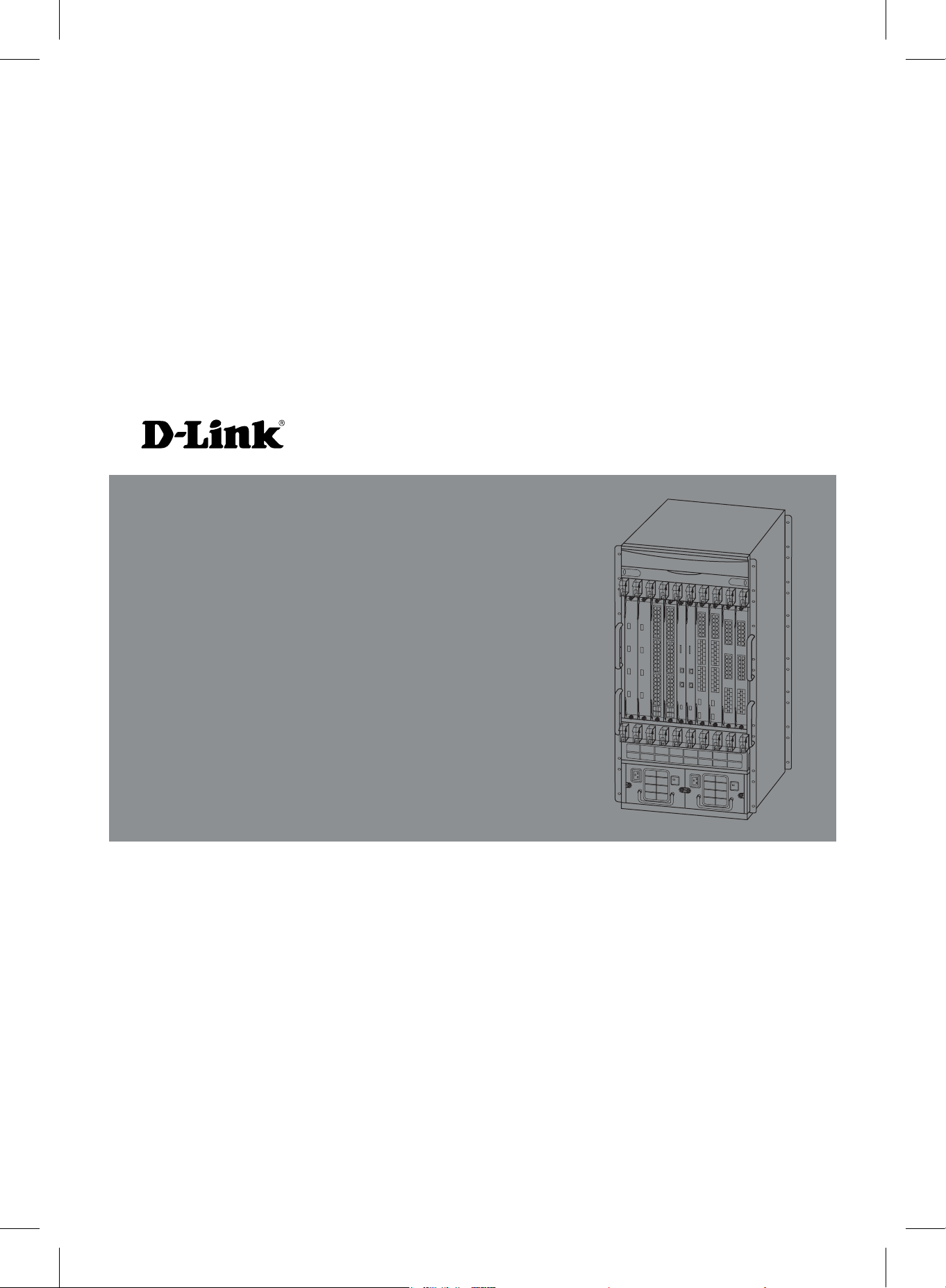
DGS-8000 Series Chassis-Based Switch
This document will guide you through the basic
installation process for your new D-Link
chassis-based switch.
DGS-8000 Series
Documentation also available on CD
and your regional D-Link Website.

Preface
Safety Warnings
This QIG will guide you through the necessary
steps for DGS-8000 series chassis-based switch
installation. Read the following safety precautions
ENGLISH
carefully before handling the product, and to avoid
injury or damage to yourself or your equipment. If
you have any questions, please contact a D-Link
customer support representative.
Product Overview
The DGS-8000 series of Ethernet switches are
modular, high-capacity, multi-service IPv6 10G
core-routing switches. The switches provide
users with powerful security protection and the
option to expand via stacking when service
demands increase. In this way, the DGS-8000
series satises the needs for both security and
performance.
All of the switches in the DGS-8000 series
support dual management modules and power
supply redundancy. The series offers two
kinds of chassis - one with 10 vertical slots
(DGS-8010) and one with 6 horizontal slots
(DGS-8006).
- The DGS-8010 supports dual
management engine modules and
provides redundant backup power for
the management engine modules and 8
service module slots.
- The DGS-8006 supports dual
management engine modules and
provides redundant backup power for
the management engine modules and 4
service module slots.
Power Supply Safety Warning
- Make sure the product has
an earthed connection before
connecting it to the power supply.
- Ensure that all the cables are
correctly connected to the
grounding electrical sockets.
- There is more than one power
input. Ensure that all the power
cables are pulled out before you
power down the system.
Static Electricity Protection Warning
- Electrostatic Sensitive Device
(ESD) inside. Always wear an
anti-ESD ring or wrist strap
when handling the switch.
Laser Safety Warning
CLASS 1 LASER PRODUCT
- Avoid looking directly at the
optical interfaces and the
openings in the optical bers, as
this may damage your eyes.
Serial Interface Safety Warning
- Hot-plugging into a serial interface
may damage the terminal.
Please power down the terminal
before inserting a cable in the
serial interface. Please also
power down before pulling a
cable out of the serial interface.
2 DGS-8000 Series Chassis-Based Switch
Fan Safety Warning
- Hazardous moving parts. Keep
your hands, clothing and body
away from the moving parts.
Transportation Safety Warning
- Weight may exceed 80 Kg.
- Don’t use this handle to lift the
chassis.
Maintenance Warning
- Users are not allowed to repair
the parts within the device.
Please contact qualied
technical personnel if necessary.
Scope
This document will guide you through the basic
installation process of your new switch. It is
intended for users who have some experience
in installing and maintaining network hardware.
We assume the reader is familiar with the terms
and concepts of Ethernet networks.
Safety Precautions for
ENGLISH
Movement
The DGS-8000 series of switches are large and
heavy. When you handle them, please observe
the following precautions:
- Turn off all power supplies and unplug all
power cables before you move the switch.
- Remove the power, fan and service modules
to reduce the weight of the chassis before
moving it over a large distance.
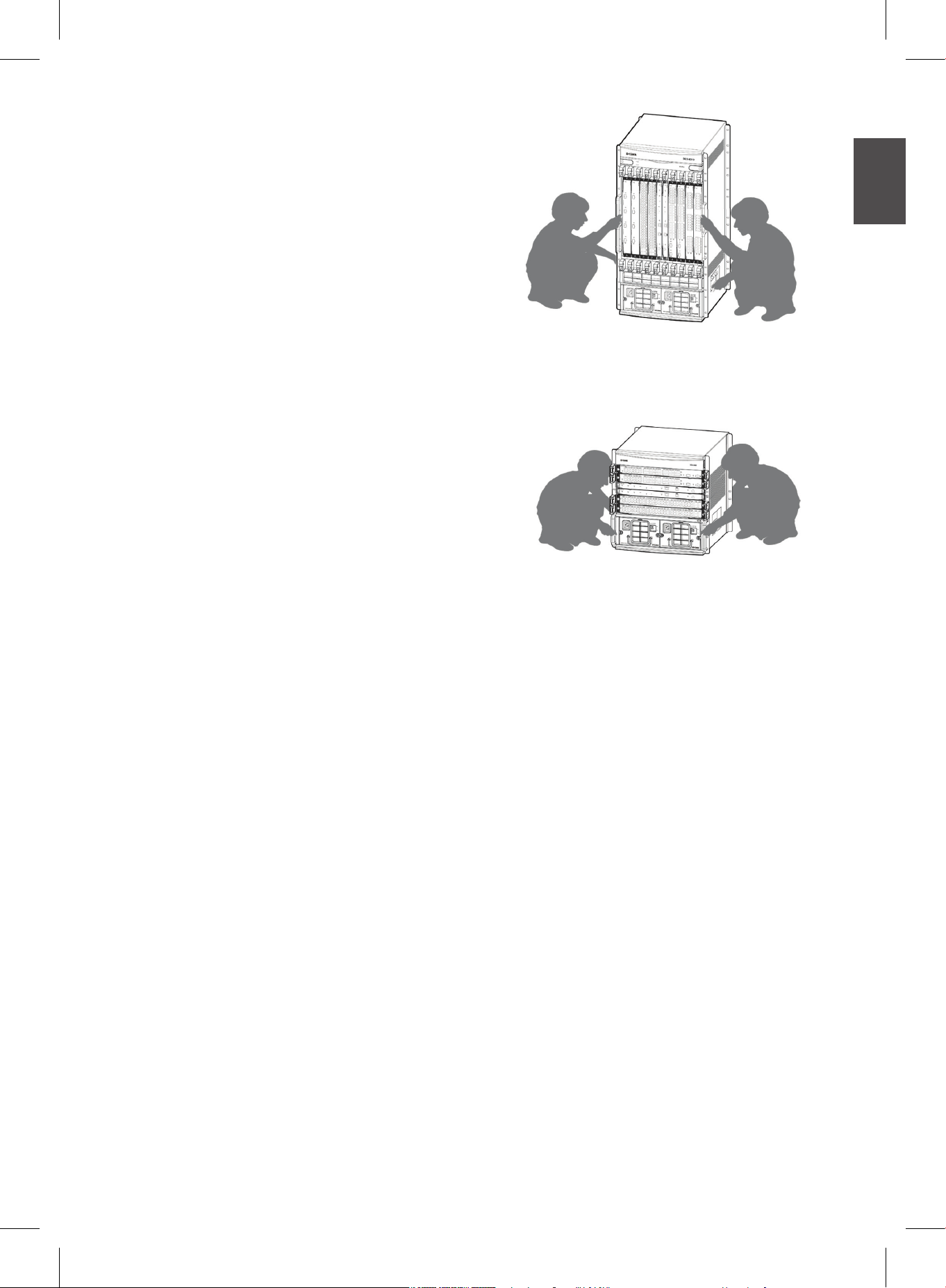
- At least two people are needed to move
the switch. Do not attempt to move the
switch by yourself.
- Keep your balance when moving the
switch and avoid injuring your legs, feet,
or wrists.
- Grasp the correct handles on both sides
of the rack. Do not grab the power system
handle, fan handle or the back-panel
handle. These handles are used to install
and remove corresponding parts, not to
bear the full weight of the switch.
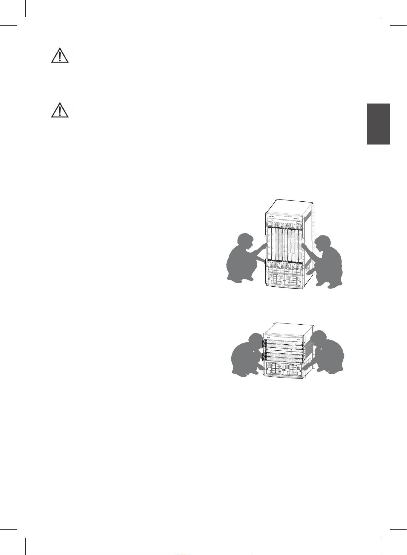
Figure 2-1 The correct way to
move the DGS-8010 switch
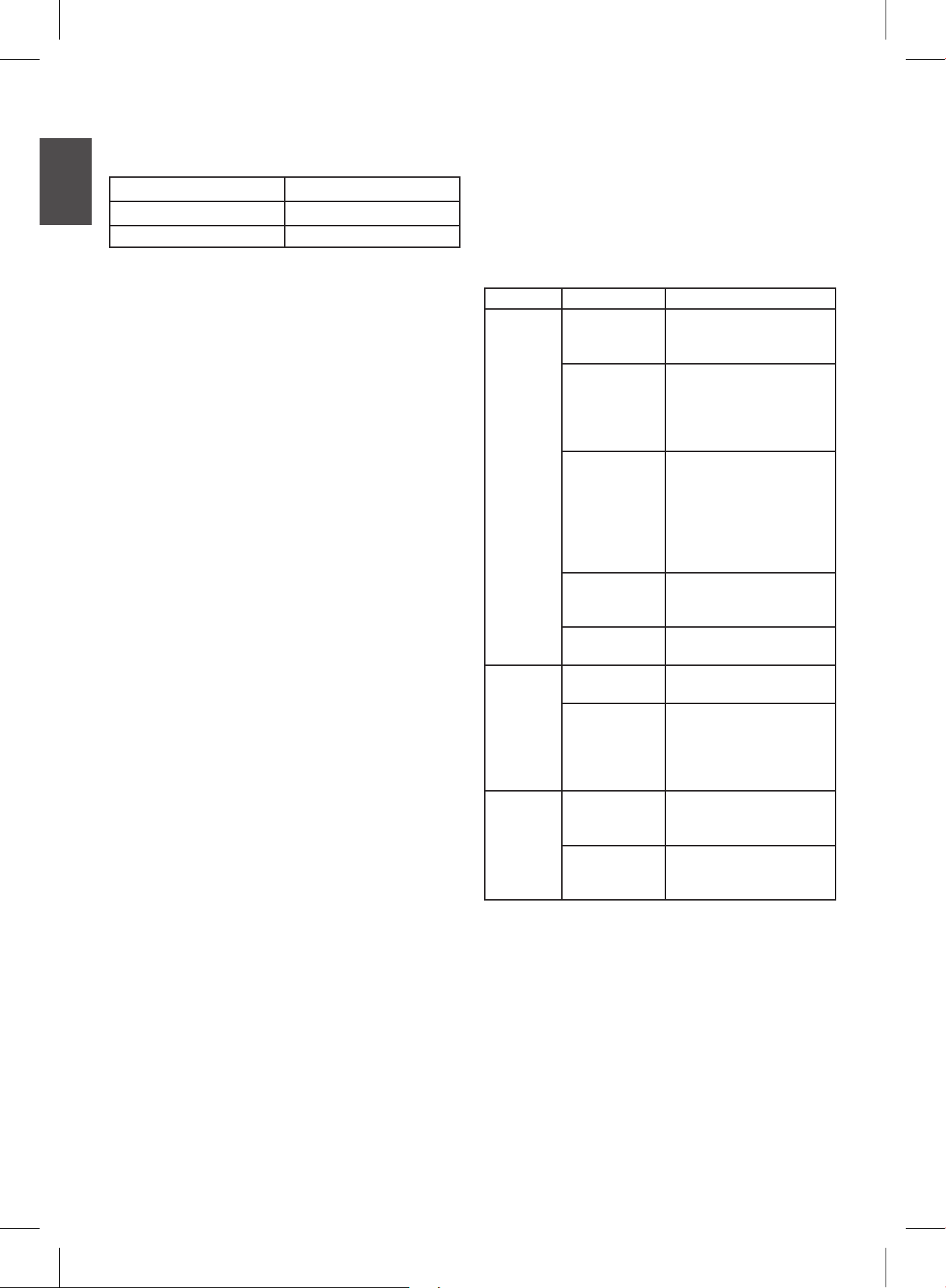
Figure 2-2 The correct way to
move the DGS-8006 switch
- The full weight of the switch could be in
excess of 80 Kg, so take extreme care
when moving it.
- To correctly move the DGS-8010, refer
to Figure 2-1 below. For the DGS-8006,
refer to Figure 2-2. Note that these
images are just schematic diagrams remove the board cards when moving the
chassis, to avoid increasing the weight of
the chassis or damaging the board cards.
DGS-8000 Series Chassis-Based Switch 3
Preparing for Installation
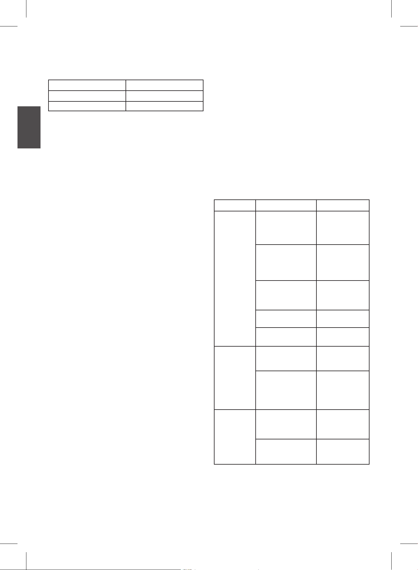
Temperature and Humidity Requirements
Power Requirements
- AC input voltage: 100 V AC ~ 120 V AC,
200 V AC ~ 240 V AC, 50/60 Hz
Operating temperature
ENGLISH
Storage temperature
Relative humidity 10% - 90%
˚C - 50 ˚C
0
˚C - 70 ˚C
-40
Static Discharge Damage Prevention
To prevent damage from static electricity, you
must pay attention to the following:
- Provide a proper ground (earth)
connection for your chassis switch.
- Dust prevention measures must be taken
in the room of installation.
- Maintain appropriate humidity levels.
(Refer to the table above.)
- Do not wear loose clothing or any other
items (such as rings or necklaces) that
could get caught in the chassis during
installation and maintenance.
- Avoid contact between your clothes and
the printed circuit board. An antistatic
wrist strap can only prevent the static
electricity on a person from damaging
the circuit board, but it cannot safeguard
against static electricity on clothing.
- Always hold the circuit board by its edges
and do not touch any integral components
or the printed circuit board.
- Always wear an antistatic wrist strap
when handling a circuit board. For
further details, refer to Static Electricity
Prevention on page 7.
System Grounding Requirements
Carefully check the grounding conditions at
the installation site according to the grounding
requirements, and install a proper grounding
system that suits the site. A good grounding
system will help to ensure stable and reliable
functioning of the switch. It also prevents
damage from lightning and limits electrical
interference. For details, refer to System
Grounding Requirements on page 6.
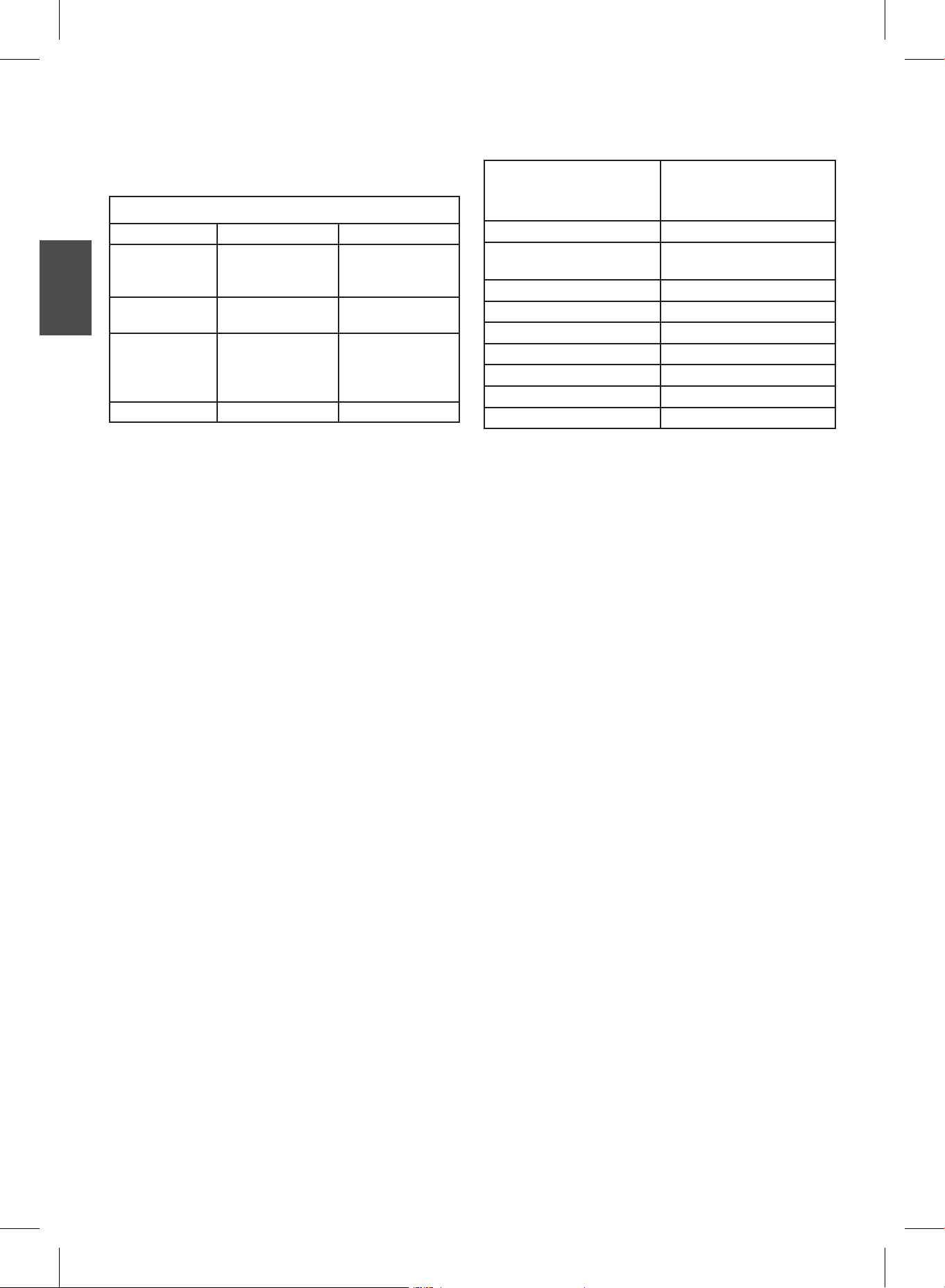
- AC input power: greater than the actual
power consumption of the whole,
collective system.
Installation Tool Requirements
Type Tools Remarks
Use this to unpack
wooden and
transportation cases.
Use this to disassemble
the chassis, power
supply, fan and modules.
Use this to connect the
interfaces.
Use this to measure the
installation positions.
Use this to mount the
chassis in the rack.
Use this to prevent static
electricity.
Use this to connect
cables and to strip the
insulation from network
cables and grounding
cables.
Use this to test
power supply and DC
resistance.
Use this to test the
insulation resistance and
grounding resistance.
Common
tools
Specialpurpose
tools
Meters
Claw hammer,
pliers
Cross
screwdriver,
straight
screwdriver,
spanner
Power supply
cables,
network
cables, optical
bers and
distribution
cables
Ruler, long
tapeline,
marker pen
Bolts, diagonal
pliers, straps
Anti-static tool
Wire stripper,
crimping pliers
Multimeter
500 V
Megohmmeter
Note: These tools are not included in the
packaging of DGS-8000 series switches. Users
need to acquire these tools in order to install
the chassis switch.
4 DGS-8000 Series Chassis-Based Switch
Installation Site Requirements
1. Place the switch in the right place.
2. If you plan to mount a switch of the
DGS-8000 series in a cabinet, you must
make sure that the cabinet meets the
following requirements:
- Install the switch in an open cabinet if
possible. If you install the switch inside
a closed cabinet, please ensure that the
cabinet has a good ventilation and heat
dissipation system.
- Ensure that the cabinet is strong enough
to bear the weight of the switch and its
installation accessories.
- Ensure that the cabinet is big enough to
leave enough space for effective heat
dissipation around all the sides of the
chassis modules, even after the switch's
side panels have been inserted.
- The cabinet should be properly grounded.
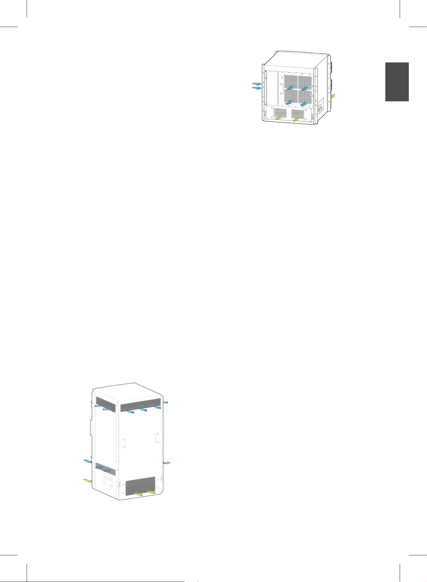
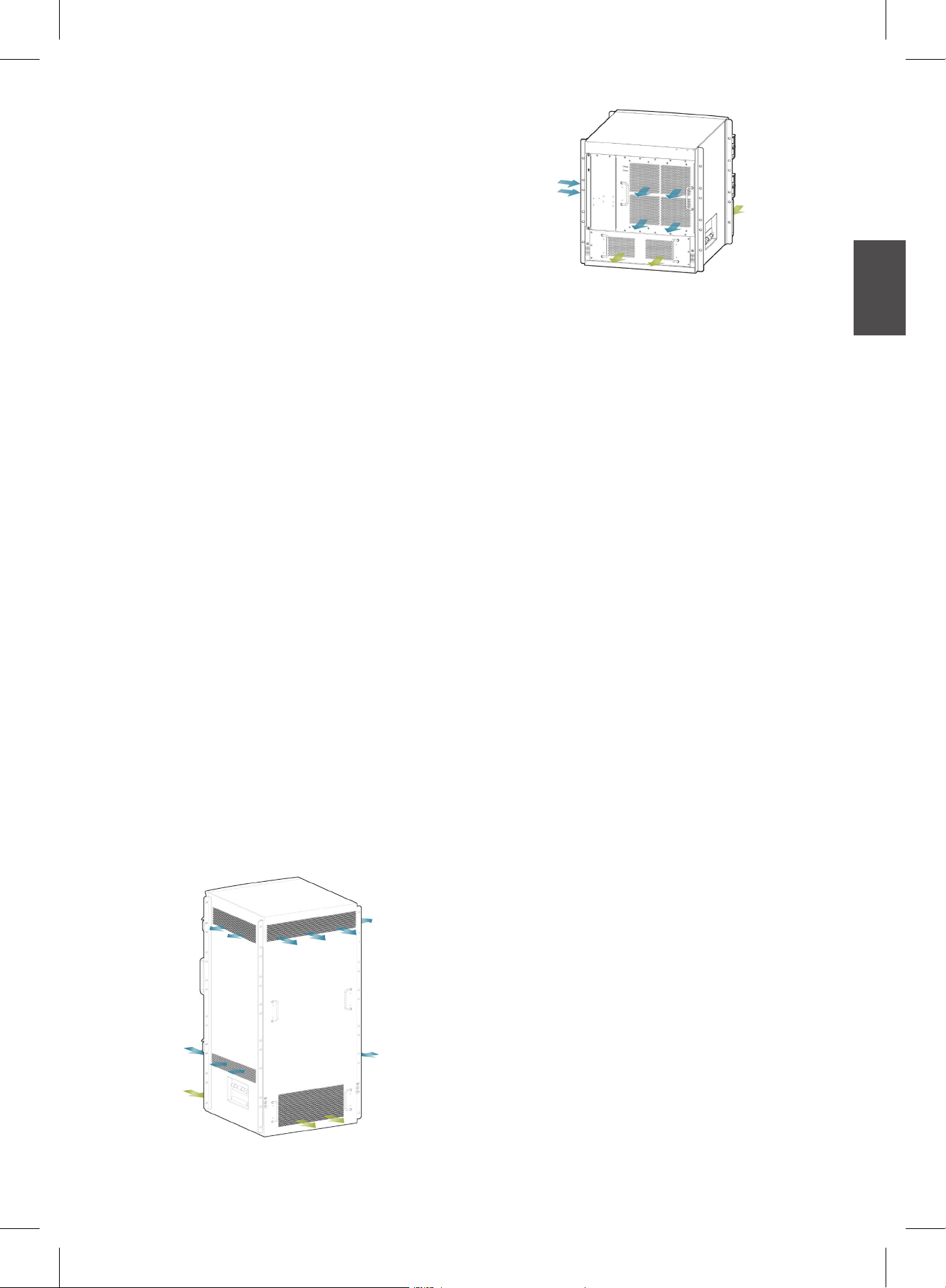
3. The gures below show the ventilation
requirements of the DGS-8000 range of
switches. You must ensure that sufcient
spacing is reserved around the ventilation
openings to ensure effective ventilation.
All connected cables should be tied into
bundles or placed on cabling racks to
minimize blockage of the air inlets and
outlets.
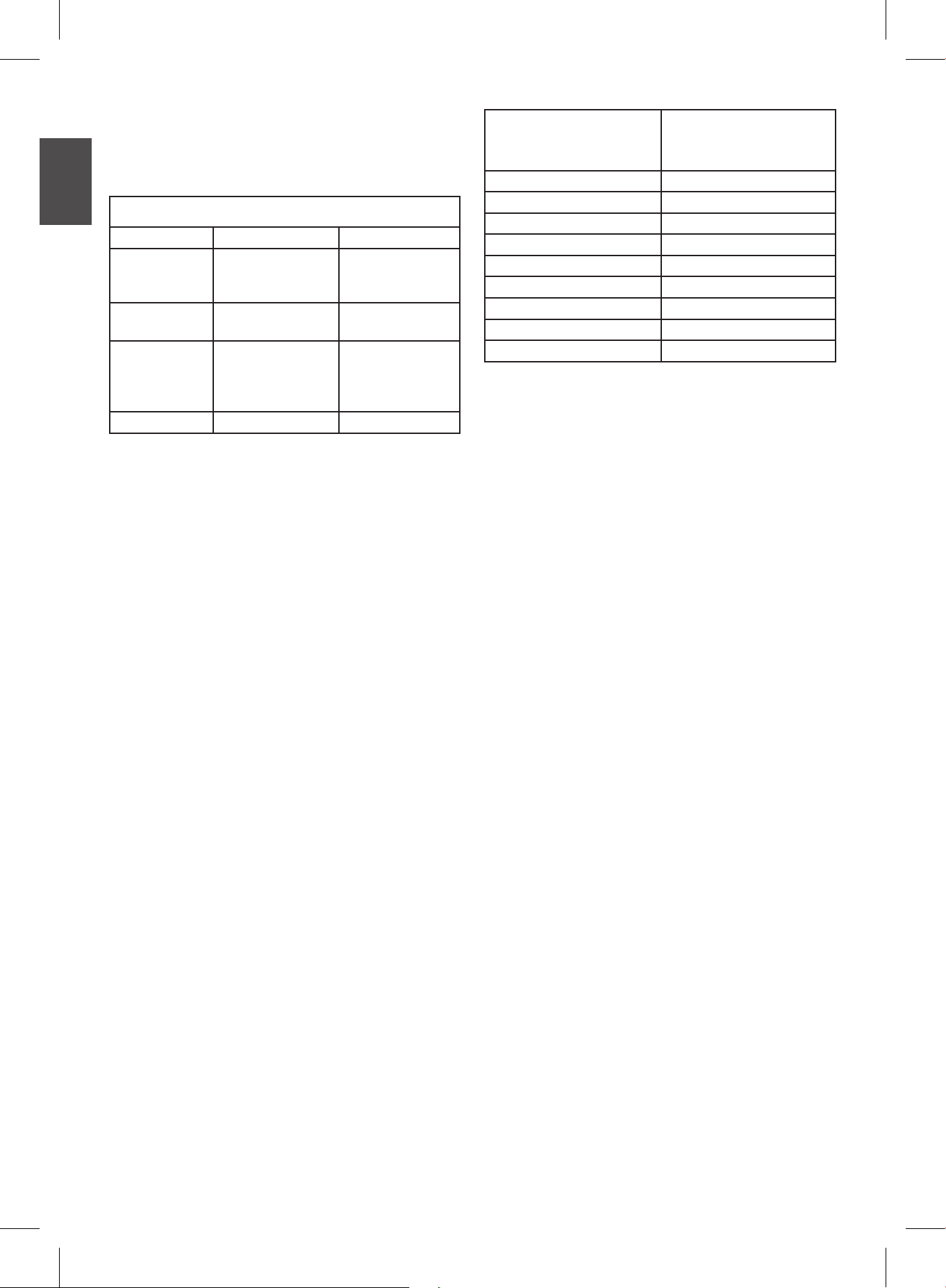
4. Refer to gures 4-1 and 4-2 below for the
ventilation areas of the DGS-8010 and
DGS-8006, respectively.
ENGLISH
Figure 4-1 Ventilation areas of the DGS-8006
Pre-start Checklist
Before powering on a DGS-8000 series switch,
make sure that:
• The fan meets current requirements. For
details, refer to the 'Fan' section below.
• The power system is suitable. For details,
refer to the 'Power Supply' section below.
• The power system is fastened properly with
screws.
• Do not power on the system during
maintenance.
• Do not work alone when potentially
hazardous conditions exist.
• Make sure that there is no potential risk in
the work area - for example, ungrounded
power and moist oors.
• Keep the chassis switch away from wet
areas.
• Be aware of the emergency power-off
switch in the room in which you are working.
If there is an accident, immediately turn off
the power switch.
• Make sure that all the power systems are
powered off when necessary.
• Ensure that the power cords are rmly
connected to the power modules.
• Ensure that the power cables are long
enough for the installation.
• Ensure that the rated current of the power
bank is not greater than 16 A and the power
bank is grounded well.
• Ensure that each power module is plugged
into a power socket of the chassis switch.
Figure 4-2 Ventilation areas of the DGS-8010
Fan
Precaution:
• The DGS-8010 and DGS-8006 use
standard fans for heat dissipation.
DGS-8000 Series Chassis-Based Switch 5
Power Supply
DGS-8000 series switches can use the
following power supplies:
ENGLISH
Model 8000-1400AC 8000-2000AC
Rated voltage
Maximum
voltage
Maximum
power output
Power cable 16 A 16 A
AC Power Parameters
100-120 V AC,
200-240 V AC,
50/60 Hz
90-264 V AC,
47-63 Hz
90-176 V~
Power:530 W
176-264 V~
Power:1400 W
100-120 V AC,
200-240 V AC,
50/60 Hz
90-264 V AC,
47-63 Hz
90-176 V~
Power:1080 W
176-264 V~
Power:2000 W
Important
• When an AC power module is used, pay
attention to the input voltage ranges. The
maximum power output of the 8000-1400AC
is different from that of the 8000-2000AC,
and their maximum power output values
change according to the input voltages.
• The AC power modules are hot swappable.
• Once AC power is switched on, the Input
and Output LEDs on the panel light up in
green.
• To prevent any damage to parts caused
by rapidly changing power cycles, do not
power on a DGS-8000 series switch within
30 seconds after powering off.
• Use the correct cables to connect the power
modules.
• Airborne dust may block the air outlet of
an air lter after a while, thereby affecting
system ventilation and heat dissipation.
Therefore, if you choose to t an air lter
on the power supply, it is recommended to
clean the lter once every three months.
• The user should select power modules
according to the collective power
consumption of all the switch modules that
will be tted into the switch. Make sure the
power modules can create enough power
to satisfy the maximum consumption of the
whole system. If the collective consumption
exceeds the output of a power module,
please purchase more power modules.
DGS-8000 Series
modules
8000-CM1 91
8000-48PC-E 121+15.4* N (See note)
8000-48TC-E 121
8000-24TC-E 77
8000-24SC-E 84
8000-4XG-E 100
8000-24SC2XG-E 100
8010-FAN 240
8006-FAN 160
Maximum power
consumption (W)
Note:
For PoE-enabled modules, the power
consumption and PoE output power of a line
card should be taken into account for power
calculations. The maximum power consumption
of the 8000-48PC-E is 121+15.4*N (Watt),
where 121 indicates the power consumption
of the line card and 15.4*N indicates the PoE
output power, with N being the number of PoE
ports used (0≤N≤48). 15.4 W is the maximum
power usage of external PoE equipment, as
specied in IEEE 802.3af (PoE specications).
• D-Link recommends setting up "1+1 dual
power system redundant mode". However,
if the total power consumption of all the
modules exceed the maximum power of a
single power system, then the redundant
backup function will not work.
• 1+1 redundancy conguration allows you
to congure different power inputs for two
power modules of the chassis switch. For
example, one for commercial power and the
other for UPS power.
• For 1+1 redundancy to work, the power
supply models must be identical.
System Grounding
Requirements
• An effective grounding system is essential
for the stable and reliable functioning of
all DGS-8000 series switches. It is also
essential for safeguarding against lightning
strikes and static interference.
• For the safety of the user and the switch,
the switch must be grounded well. The
electric resistance between the chassis and
the ground must not exceed 1 ohm.
6 DGS-8000 Series Chassis-Based Switch
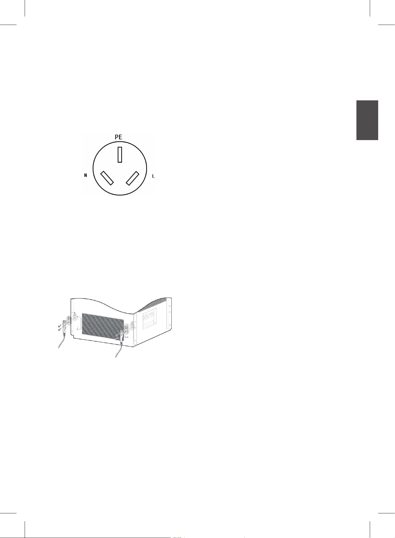
• Provide two kinds of grounding in the
equipment room:
- Safe Grounding - guarantees your safety
and that of the equipment. A typical
example is the AC protection grounding of
the 3-core socket of a power-supply bank.
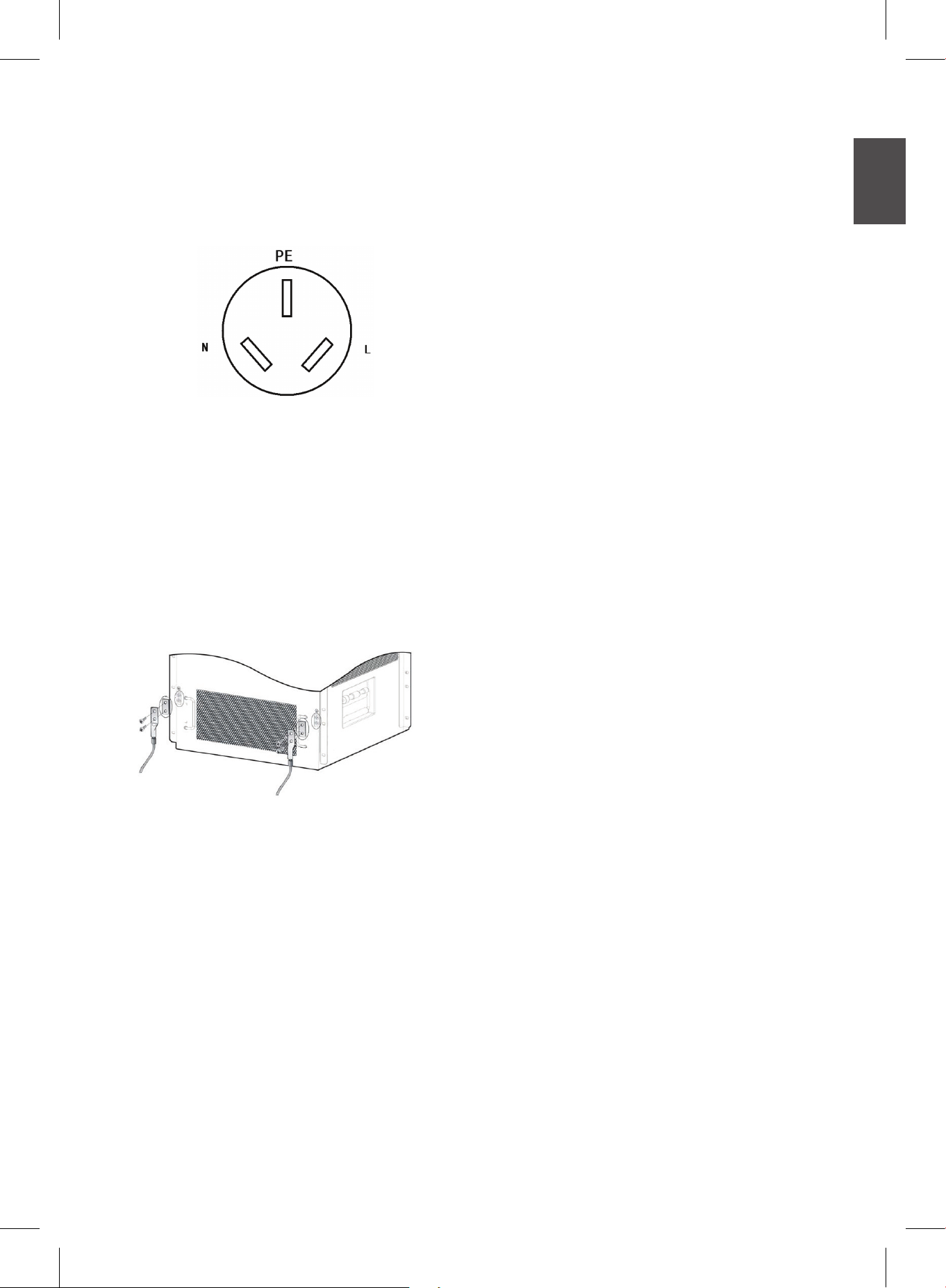
Figure 8-1 The three-core socket of a
power-supply bank
- Lightning-Prevention Grounding -
prevents lightning strikes from affecting
the user and the switch. It includes a
lightning rod, down conductor, and
grounding system.
DGS-8000 Series - Grounding Steps
• Release and remove the nut on the
grounding pole at the back of the chassis.
• Lock the terminal of the grounding cable to
the grounding pole.
• Tighten the nut.
• Connect the other end of the grounding
cable to the grounding pole or grounding
bar of the machine room.
Static Electricity Prevention
To avoid damage from static electricity, please
conform to the following guidelines:
• Ensure that the static electricity prevention
measures are taken in sites where switches
are installed.
• Always wear an antistatic strap when
working around any electronic circuitry.
An antistatic wrist strap is included in the
packaging of DGS-8000 series switches.
• Hold a circuit board by its edges. Do not
touch any components on the PCB.
ENGLISH
Rack-grounding poles
Figure 8-2 Grounding poles on the back of the
chassis of a DGS-8000 switch
DGS-8000 Grounding Method:
• Connect the grounding poles on the back of
the chassis of a DGS-8000 series switch to
the grounding pole or grounding bar of the
machine room through grounding cables.
• Connect the power modules to the power
socket using 3-core AC cables. The socket's
AC protection grounding is also connected
to the grounding pole or grounding bar
of the equipment room. This method is
specically for a DGS-8000 series chassis
that uses AC power.
Follow these steps to correctly use an antistatic
wrist strap:
1. Put your hand through the loop of the
antistatic wrist strap.
2. Tighten the strap lock and make sure that
the metal part of the antistatic wrist strap is
in contact with your skin.
3. Insert the end of the wrist strap into the
antistatic wrist strap jack of the switch rack,
or clip it to the grounding pole of the rack.
The antistatic wrist strap jack is located on
the front panel of the rack and marked in
yellow as "ESD".
4. Make sure the antistatic wrist strap is
grounded well and the DC electric
resistance between the body and the
ground is in the range of 1 to 10 mega ohm.
DGS-8000 Series Chassis-Based Switch 7

Troubleshooting
Issue 1: The AC power module does not work.
Details:
ENGLISH
- The Status LED of each line card is OFF,
the Power LED of the fan tray is OFF, and
the fan does not work. The LED on the
panel of the power module is OFF.
Procedure:
1. Place the switches of all the power modules
to OFF. Check if the cables of the cabinet
have been correctly connected.
2. Check whether the power cables are tightly
connected to the cabinet power sockets and
power modules.
3. Check whether the power modules are
installed correctly. If necessary, check
whether the connectors on the backboard of
the power system are tightened.
4. Check whether the supply power output
consumption meets the overall power
consumption requirements, if it is less than
the consumption required by the system,
please purchase another power module.
Issue 2: An exception occurs to the LEDs
when line cards are powered on.
Details:
- The Status LED of the line card is OFF,
ashing, or RED. The Link/ACT LED of
the line card is solid ON when no network
cable or ber is plugged.
Procedure:
1. Check if the line card is rmly inserted. If so,
install the line card again and ensure that
it is inserted into slot before you tighten the
fastening screws.
2. If the line card still does not work, check if
the connector of the slot on the backplane is
loose. If yes, insert the board to another slot
for a try.
3. If the slot and connection are not the cause,
return the line card for repair.
Issue 3: The LED is abnormal after a line card
works for some time.
Details: The Status LED of the line card is OFF
or RED. The Link/ACT LED of the line card
is solid ON when no network cable or ber is
plugged. The fault remains after restart.
Procedure:
1. Check if the board gets loose. If so, install
the line card again and ensure that it is
inserted into slot before you tighten the
fastening screws.
2. If the line card still does not work, check if
the connector of the slot on the backplane is
loose and check if the guide rail of the slot is
deformed. If so, insert the board to another
slot for a try.
3. If the slot and connection are not the cause,
return the line card for repair.
Issue 4: The LED of the control module is
abnormal.
Details: The LED of the control module
becomes abnormal after the board is powered
on or works for some time. For example, the
Status LED is ashing or OFF, and the Alarm
LED is red.
Procedure:
1. Check if the control module gets loose. If so,
install the control module again and ensure
that it is inserted into slot, before you tighten
the fastening screws.
2. If the line card still does not work, check if
the connector of the slot on the backplane is
loose and check if the guide rail of the slot is
deformed. If yes, insert the board to another
slot for a try
3. If the slot and connection are not the cause,
return the control module for repair.
4. When the Alarm LED is red, the cause may
be the fault of another module in the system,
in which case you can check other modules
(for example, line card, fan, power, and
overheating) for any alarm. If yes, you should
rst handle the faults of other modules. You
can also identify the faults by logging in to
the management software.
Issue 5: The fan tray does not work or an
exception occurs to the LED.
Details: After the system starts, the fans in the
fan tray do not work or the Power LED is OFF,
and the Alarm LED is red.
8 DGS-8000 Series Chassis-Based Switch

Procedure:
1. Check if the connection between the fan
tray and the backplane is secure and if the
connector gets loose.
2. If the connection is secure, you need to
replace the fan tray.
Issue 6: The serial port console has no output.
Details: After the system is started, the serial
port console does not display any information.
Procedure:
1. Check whether serial port cables are
connected correctly and whether the
connected serial port is identical with that
congured on the super terminal.
2. Check whether the conguration of the serial
port on the super terminal is the same as
that described in DGS-8000 Series Software
Conguration Guide. If not, modify the serial
port conguration parameters.
3. If there is still no serial port printed infor-
mation, please contact D-Link Customer
Service Department for technical support.
Issue 7: The serial port console outputs
illegible characters.
Details: The serial port console outputs
illegible characters.
Procedure:
1. Such problem is related to the settings of the
serial port. Check whether serial port cables
are connected correctly and whether the
settings of such parameters as the baud rate
match those on the super terminal.
2. Check whether it is the standard cable of
serial interface.
Issue 8: The system login password is lost.
Details: The system login password of the
switch is forgotten or lost, and so it is not
possible to congure the data.
Procedure:
There are two methods:
Method 1: Delete the conguration le. (This
method is applicable for the user who needs to
congure the switch again)
1. Launch the super terminal and set the name
of new connection to 9600.
2. Click OK. Set COM1 with its baud rate as
the one of the switch, 9600 by default.
3. Power on the switch and press Ctrl+C keys
continuously to enter the switch Ctrl> CLI.
4. Delete a le. Input the delete cong.text.
Press the Enter.
5. The” Are you sure you want to delete "
cong.text "?[No/yes]” is shown on the
interface. Input y, press Enter to delete it.
6. Input the “dir” to show current le conguration. The result shows that the cong.text
le is removed.
7. Input “load” under Ctrl> to load main
program.
8. At this time, you can enter the EXEC
privilege mode without demanding password.
Method 2: Rename cong.text as cong.bak,
which will not cause loss of conguration (this
method is applicable for the user who needs
save the conguration)
1. Power on the switch and press Ctrl+C keys
continuously to enter the switch Ctrl> CLI.
2. Input “ rename cong.text cong.bak”
under the Ctrl>. Press Enter.
3. Input “dir” under the Ctrl> to check whether
the cong.text has been renamed as cong.
bak.
4. After the le is renamed successfully, input
‘load” under Ctrl> to load main program.
5. At this time, you can enter the EXEC
privilege mode without demanding password.
Input “copy ash:cong.bak ash:cong.
text” after the prompt # to restore the original
conguration le.
6. Input “del cong.bak” after the prompt # to
delete the cong.bak le.
7. Power cycle the switch, log on the switch
with password to view the original conguration.
ENGLISH
DGS-8000 Series Chassis-Based Switch 9

Additional Information
If you are encountering problems setting up
your network, please refer to the User’s Guide
that came with the switch. It contains many
ENGLISH
more rules, charts, explanations and examples
to help you get your network up and running.
Additional help is available through our ofces
listed online. To learn more about D-Link
products or marketing information, please visit
the website http://www.dlink.com.tw; for any
support issue, please visit the website http://
support.dlink.com.tw, which will re-direct you to
your appropriate local D-Link website.
10 DGS-8000 Series Chassis-Based Switch
Building Networks for People
Schnellinstallationsanleitung
Chassis basierter Switch der Produktreihe
DGS-8000
Diese Anleitung führt Sie durch den allgemeinen
Installationsprozess für Ihren neuen Chassis
Switch von D-Link.
DGS-8000 Produktreihe
Die Dokumentation ist auch auf CD und über
die D-Link-Website Ihres landesspezischen
Standortes verfügbar.
Vorwort
Sicherheitswarnungen
Diese Anleitung führt Sie Schritt für Schritt
durch die Installation des Chassis Switch der
Produktreihe DGS-8000. Bitte lesen Sie die
folgenden Sicherheitsvorkehrungen sorgfältig
durch, bevor Sie das Produkt verwenden, um
Verletzungen von Personen oder Beschädigungen
an Ihrem Gerät zu vermeiden. Sollten Sie
Fragen haben, wenden Sie sich bitte an einen
Kundendienstmitarbeiter von D-Link.
DEUTSCH
Produktübersicht
Bei den Ethernet-Switches der Produktreihe
DGS-8000 handelt es sich um modulare IPv6
10G Core-Routing-Switches, die sich durch
hohe Speicherkapazitäten und Multi-Service
auszeichnen. Sie bieten Ihnen leistungstarke
Sicherheits- und Schutzfunktionen sowie
Erweiterungsoptionen über Stacking-Verfahren,
sobald sich Ihre Serviceerfordernisse erhöhen.
Auf diese Weise erfüllt die DGS-8000
Produktreihe sowohl Sicherheits- als auch
Leistungsanforderungen gleichermaßen.
Alle Switches der DGS-8000 Produktreihe
unterstützen Dual-Management-Module und
Stromversorgungsredundanz. Die Produktreihe
bietet zwei Chassis-Typen - einen mit 10 vertikal
ausgelegten Slots (DGS-8010) und einen mit 6
horizontal ausgelegten Slots (DGS-8006).
und-hinweise
Sicherheitshinweise zur
Stromversorgung
- Vor dem Anschluss an die
Stromversorgung muss
sichergestellt werden, dass das
Produkt einen ordnungsgemäßen
Erdungsanschluss aufweist.
- Stellen Sie sicher, dass alle Kabel
korrekt an geerdete Steckdosen
angeschlossen sind.
- Die Stromeinspeisung erfolgt über
mehr als einen Eingang. Stellen
Sie deshalb sicher, dass alle
Netzkabel herausgezogen sind,
bevor Sie das System abschalten.
Warnhinweise zum Schutz vor
statischer Auadung
- ESD (Schutz vor elektrostatischer
Entladung (EN 61340-5-1)
integriert. Bei Handhabung
des Switch sollte immer für
ESD-Personenerdung gesorgt
sein (z. B. Erdungsarmband mit
Erdungskabel).
Sicherheitswarnung zum Laser
LASERPRODUKT DER KLASSE 1
- Der DGS-8010 unterstützt
Dual-Management-Engine-Module und
liefert redundante Backup-Leistung für
die Management-Engine-Module und 8
Service-Modul-Slots.
- Der DGS-8006 unterstützt
Dual-Management-Engine-Module und
liefert redundante Backup-Leistung für
die Management-Engine-Module und 4
Service-Modul-Slots.
- Sehen Sie nie direkt auf die
optischen Schnittstellen und
Öffnungen in den Glasfaserleitern
oder -komponenten, da dies zu
Augenschäden führen kann.
Sicherheitswarnung zur seriellen
Schnittstelle
- Wenn ein Kabel bei
eingeschaltetem Gerät und
während des regulären Betriebs
an die serielle Schnittstelle
angeschlossen wird (so genanntes
Hot Plugging), können Schäden
an dem Anschluss entstehen.
Vor dem Anschließen/Abziehen
von Kabeln an/von der seriellen
Schnittstelle muss das Terminal
ausgeschaltet werden.
Sicherheitswarnung zum Lüfter
- Bewegliche Teile als
Gefahrenquelle: Halten Sie Ihre
Hände, Kleidung und Ihren Körper
von beweglichen Teilen fern.
12 DGS-8000 Series Chassis-Based Switch
Sicherheitswarnung zum Transport
- Das Gewicht des Systems kann
80 Kg überschreiten.
- Verwenden Sie diesen Griff nicht
zum Heben des Chassis.
Warnungshinweis zur Wartung
- Die Reparatur von Bauteilen im
Gerät sind dem Benutzer nicht
gestattet. Wenden Sie sich bitte
ggf. an entsprechend geschultes
Fachpersonal.
Geltungsbereich
Diese Anleitung führt Sie durch den allgemeinen
Installationsprozess Ihres neuen Switch. Sie
richtet sich an Personen, die Erfahrung mit
der Installation und Wartung von NetzwerkHardware haben. Ein Verständnis der gängigen
Begriffe und Konzepte von Ethernet-Netzen wird
vorausgesetzt.
dem Installieren und Entfernen der
entsprechenden Teile und nicht zum
Tragen des Gesamtgewichts des Switch.
- Das Switch-Gesamtgewicht kann mehr
als 80 Kg betragen. Es ist deshalb beim
Bewegen oder Transportieren des Geräts
mit äußerster Vorsicht und Sorgfalt
vorzugehen.
- Die Abbildung 2-1 unten zeigt die korrekte
Haltung beim Heben/Bewegen des
DGS-8010. Für den DGS-8006 gilt die
Abbildung 2-2. Beachten Sie, dass es
sich bei diesen Abbildungen lediglich um
schematische Diagramme handelt -
entfernen Sie beim Transport die Board
Cards, um deren Beschädigung zu
verhindern oder das Gewicht zu reduzieren.
DEUTSCH
Sicherheitsvorkehrungen für
den Transport
Die DGS-8000 Produktreihe der Switches sind groß
und schwer. Bei Handhabung sollten deshalb die
folgenden Vorsichtsmaßnahmen unbedingt beachtet
werden:
- Vor dem Transport oder dem Bewegen
des Geräts müssen alle Netzteile bzw.
Stromversorgungsgeräte ausgeschaltet und
alle Stromkabel abgezogen werden.
- Sollte ein längerer Transport anstehen,
sollten Lüfter-, Stromzufuhr- und
Servicemodule zur Reduzierung des
Chassis-Gewichts entfernt werden.
- Zum Bewegen des Switch sind mindestens
zwei Personen erforderlich. Versuchen Sie
nicht, den Switch allein zu heben oder zu
bewegen.
- Achten Sie beim Heben oder Transportieren
des Switch auf eine den Rücken schonende
Haltung und entsprechende Bewegungen,
um Verletzungen oder Überbelastungen
Ihres Rückens, Ihrer Beine, Füße oder
Handgelenke zu vermeiden.
Abbildung 2-1 - Die korrekte Haltung beim
Bewegen des DGS-8010 Switch
Abbildung 2-2 - Die korrekte Haltung beim
Bewegen des DGS-8006 Switch
- Fassen Sie unbedingt an den dafür
vorgesehenen Griffen auf beiden
Seiten des Racks an, nicht am Griff für
das Leistungssystem, den Lüfter oder
die Rückplatte. Diese Griffe dienen
DGS-8000 Series Chassis-Based Switch 13
Installationsvorbereitungen
Erforderliche Temperatur und Luftfeuchtigkeit
Betriebstemperatur
Lagertemperatur
Relative Luftfeuchtigkeit 10% - 90%
Verhindern von Schäden durch statische
Entladung
Beachten Sie unbedingt zur Vermeidung von
DEUTSCH
Schäden durch statische Auadung die folgenden
Richtlinien:
- Sorgen Sie für eine ordnungsgemäße
Masseverbindung und Erdung für Ihren
Chassis Switch.
- Im Raum, der für die Installation zur
Verfügung steht, sind Maßnahmen zur
Vermeidung von Staubentwicklung zu
ergreifen.
- Zur Gewährleistung eines normalen
Betriebs sind die passenden Werte für
Temperatur und Luftfeuchtigkeit im
Geräteraum einzuhalten. (Entsprechende
Informationen nden Sie in der Tabelle unten.)
- Tragen Sie bitte keine weiten
Kleidungsstücke oder andere Artikel (wie
z. B. Ringe oder Halsketten), die sich
während der Installation oder Wartung des
Chassis im Gerät verfangen könnten.
- Vermeiden Sie den Kontakt zwischen
Ihrer Kleidung und der elektronischen
Leiterplatte. Ein Erdungsarmband
verhindert nur, dass die elektrostatische
Auadung einer Person die Leiterplatte
beschädigt, aber nicht die elektrostatische
Auadung der Kleidung.
- Fassen Sie die Leiterplatte (auch Platine
oder gedruckte Schaltung genannt) an
ihren Rändern an und vermeiden Sie
jegliche Berührung ihrer Komponenten.
- Tragen Sie bei der Handhabung einer
elektronischen Leiterplatte immer ein
Erdungsarmband. Weitere Informationen
nden Sie unter 'Verhinderung statischer
Auadung' auf Seite 17.
Erdungsvoraussetzungen für das System
Überprüfen Sie, dass die Erdungsbedingungen
am Ort der Installation den Erdungsanforderungen entsprechen und installieren Sie eine
ordnungsgemäße der Anlage und den örtlichen
Gegebenheiten gerechte Erdung des Systems.
˚C - 50˚C
0
˚C - 70˚C
-40
Eine ordnungsgemäße Erdung trägt zum stabilen
und zuverlässigen Betrieb des Switch bei. Sie
verhindert außerdem Schäden durch Blitzschlag
und begrenzt das Risiko elektrischer Störungen.
Details dazu nden Sie unter 'Erdungsvoraussetzungen für das System' auf Seite 16.
Leistungsbedarf
- Eingangswechselspannung: 100 V ~ 120 V
Wechselstrom,
200 V ~ 240 V Wechselstrom, 50/60 Hz
- Eingangswechselstrom: höher als der
tatsächliche Stromverbrauch des kollektiven
Gesamtsystems.
Voraussetzungen und Anforderungen für die
Verwendung der Installationswerkzeuge
Art Werkzeuge Anmerkungen
Verwenden Sie diese
zum Auspacken
der Holz- und
Transportkisten.
Zum
Auseinanderbauen
Gehäuse (Chassis),
Netzteil, Lüfter und
Modulen.
Zur Verbindung der
Schnittstellen.
Zum Abmessen der
Installationspositionen.
Zur Chassis-Montage
im Rack.
Zur Verhinderung
elektrostatischer
Auadung.
Zum Anschließen von
Kabeln und Abziehen
der Ummantelung bei
den Netzwerk- und
Erdungskabeln.
Zum Testen der
Stromversorgung
und des
Gleichstromwiderstands.
Zum Testen des
Isolations- und
Erdungswiderstands.
von
Allgemeine
Werkzeuge
Spezialwerkzeuge
Messgeräte
Klauenhammer, Zange
Kreuzschlitzschraubendreher,
gerader Schraubendreher,
Schraubenschlüssel
Netzgerätekabel,
Netzwerkkabel,
Glasfaserkabel und
Verteilerkabel
Lineal, langes Maßband,
Markierstift
Schrauben,
Diagonalzange, Riemen
Erdungsmaterial
Abisolierzange,
Crimpzange
Multimeter
500 V-Widerstandsmessgerät
Hinweis: Diese Werkzeuge sind nicht im Lieferumfang der Switches der DGS-8000 Produktreihe
enthalten. Zur Installation des Chassis Switch
sollten diese Werkzeuge besorgt werden und
bereitliegen.
14 DGS-8000 Series Chassis-Based Switch
Voraussetzungen des
Installationsstandorts
1. Stellen Sie den Switch an einer für ihn
geeigneten Stelle auf.
2. Falls einen Switch der Produktreihe
DGS-8000 in einem Schrank aufgestellt
werden soll, stellen Sie bitte sicher, dass die
folgenden Anforderungen erfüllt werden:
- Installieren Sie den Switch nach Möglichkeit
in einem offenen Schrank. Wenn der Switch
in einem geschlossenen Schrank installiert
wird, ist auf eine ausreichende Lüftung und
Wärmeableitung zu achten.
- Der Schrank muss das Gewicht des Switch
einschließlich des Installationszubehörs
tragen können.
- Im Schrank muss ausreichend Platz für
eine wirksame Wärmeableitung auf allen
Seiten der Chassis-Module sein, auch
nachdem die Seitenpaneelen des Switch
angebracht sind.
- Das Schrankgehäuse muss ordnungsgemäß geerdet werden.
3. In den folgenden Abbildungen werden die
Erfordernisse bei der Lüftung der DGS-8000
Switch-Produktreihe dargestellt. Stellen sie
sicher, dass in der Nähe der Lüftungsöffnungen
ausreichend Platz ist, um eine ordnungsgemäße
Belüftung zu ermöglichen. Alle angeschlossenen
Kabel sollten in Bündeln zusammengefasst
oder im Kabelfach platziert werden, damit sie
die Lufteinlässe und Lüftungsöffnungen nicht
versperren.
4. In den Abbildungen 4-1 bzw. 4-2 unten sind
die Lüftungsbereiche des DGS-8010 bzw.
DGS-8006 dargestellt.
DEUTSCH
Abbildung 4-1 - Belüftungsbereiche des DGS-8006
Prüiste vor dem Start
Stellen Sie vor dem Einschalten eines Switch der
Produktreihe DGS-8000 Folgendes sicher:
• Der Lüfter entspricht den aktuellen
Anforderungen. Nähere Angaben dazu nden
Sie weiter unten im Abschnitt 'Lüfter'.
• Das die eingesetzten Netzteile für das zur
Verfügung stehende Wechselstromnetz
geeignet sind. Nähere Angaben dazu
nden Sie weiter unten im Abschnitt
'Stromversorgung'.
• Stellen Sie sicher, dass die Netzteile
ordnungsgemäß mit Schrauben befestigt ist.
• Schalten Sie das System nicht während
Wartungsarbeiten an.
• Arbeiten Sie niemals allein, wenn potentiell
gefährliche Bedingungen vorliegen.
• Stellen Sie sicher, dass im Arbeitsbereich
keine potentiellen Risiken und Gefahrenquellen
bestehen, wie beispielsweise nicht geerdete
Elemente und feuchte oder nasse Böden.
• Halten Sie den Chassis Switch von
Feuchtbereichen fern.
• Stellen Sie sicher, dass Sie wissen, wo sich
der Not-Aus-Schalter in dem Raum bendet,
in dem Sie arbeiten. Sollte ein Notfall eintreten,
schalten Sie sofort diesen Schalter aus.
• Vergewissern Sie sich, dass alle
Stromzufuhrsysteme, wenn erforderlich,
ausgeschaltet sind.
• Stellen Sie sicher, dass Netzkabel fest an den
Netzteilen angeschlossen sind.
• Stellen Sie sicher, dass alle Netzkabel für die
Installation lang genug sind.
• Stellen Sie sicher, dass der Nennstrom der
Wechselstromversorung nicht höher ist als 16
A und diese gut geerdet ist.
• Stellen Sie sicher, dass jedes Netzteil an
einen entsprechenden Stromanschluss des
Chassis Switch angeschlossen ist.
Abbildung 4-2 - Belüftungsbereiche des DGS-8010
Lüfter
Vorsichtsmaßnahmen:
• Zur Wärmeableitung verwenden der DGS-8010
und der DGS-8006 Standardlüfter.
DGS-8000 Series Chassis-Based Switch 15
Stromversorgung
Die folgende Stromzufuhr kann für Switches der
DGS-8000 Produktreihe genutzt werden:
Wechselstromparameter
Modell 8000-1400AC 8000-2000AC
100-120 V AC,
Nennspannung
Maximalspannung
DEUTSCH
Maximale
Ausgangsleistung
Stromkabel 16 A 16 A
200-240 V AC,
50/60 Hz
90-264 V AC,
47-63 Hz
90-176 V~ Leistung:
530 W
176-264 V~ Leistung:
1400 W
100-120 V AC,
200-240 V AC,
50/60 Hz
90-264 V AC,
47-63 Hz
90-176 V~ Leistung:
1080 W
176-264 V~ Leistung:
2000 W
eines Netzteils überschreiten, sollten weitere
Netzteile erworben und eingesetzt werden.
Module der DGS-8000
Produktreihe
8000-CM1 91
8000-48PC-E
8000-48PC-E 121
8000-24TC-E 77
8000-24SC-E 84
8000-4XG-E 100
8000-24SC2XG-E 100
8010-FAN 240
8006-FAN 160
Maximaler
Stromverbrauch (W)
121+15.4* N (Siehe
Hinweis)
Wichtig
• Wird ein Wechselstromnetzteil verwendet,
sind die Eingangsspannungsbereiche zu
beachten. Die maximale Ausgangsleistung
des 8000-1400AC Netzteils unterscheidet
sich von der des 8000-2000AC Netzteils, und
deren Höchstwerte ändern sich entsprechend
der Eingangsspannungen.
• Die Wechselstromnetzteile sind 'Hot-Swapfähig' (Wechsel und Wechselbarkeit von
Systemkomponenten und Modulen im laufenden
Betrieb des Systems).
• Sobald der Wechselstrom (AC) eingeschaltet
ist, leuchten die Eingangs- und Ausgangs-LEDs
auf dem Bedienfeld grün.
• Um Schäden an Geräteteilen aufgrund
schnellen Aus- und Einschaltens zu
verhindern, schalten Sie einen Switch der
Produktreihe DGS-8000 nicht innerhalb von 30
Sekunden nach dem Abschalten ein.
• Verwenden Sie die korrekten Kabel zum
Anschließen der Netzteile.
• Staubhaltige Luft kann mit der Zeit die
Luftauslässe eines Luftlters verstopfen und
damit die Lüftung und Wärmeableitung des
Systems beeinträchtigen. Wenn Sie also einen
Luftlter an der Stromversorgung anbringen, ist
es ratsam, den Filter alle drei Monate zu reinigen.
• Die Netzteile sollten gemäß des kollektiven
Stromverbrauchs aller Switch-Module
ausgewählt werden, die im Switch-System
installiert werden. Vergewissern Sie sich, dass
die Netzteile ausreichend Leistung erbringen
können, um dem maximalen Verbrauch des
gesamten Systems zu genügen. Sollte der
kollektive Verbrauch die Ausgangsleistung
Hinweis:
Für PoE-fähige Module ist der Stromverbrauch
und die PoE-Ausgangsleistung einer Linecard
bei Stromberechnungen zu berücksichtigen. Der
maximale Stromverbrauch des 8000-48PC-E
ist 121+15,4*N (Watt), wobei die Zahl 121 den
Stromverbrauch der Linecard und 15,4*N die
PoE-Ausgangsleistung angibt (N ist die Anzahl
der verwendeten PoE-Ports (0≤N≤48)).
15,4 W ist die maximale Leistungsaufnahme
externer PoE-Geräte, wie in IEEE 802.3af
(PoE-Spezikationen) angegeben.
• D-Link empehlt das Einrichten des "1+1
Dual Power System Redundanzmodus". Falls
jedoch der gesamte Stromverbrauch aller
Module die maximale Leistung eines einzigen
Powersystems übersteigt, funktioniert die
Redundanz-Backup-Funktion nicht.
• Die Konguration einer 1+1 Redundanz
ermöglicht es Ihnen, unterschiedliche
Leistungszufuhr für zwei Netzteile des
Chassis Switch zu kongurieren, eine z. B. für
Netzstromversorgung und die andere für eine
USV-Stromzufuhr.
• Damit die 1+1 Redundanz genutzt werden
kann, müssen die Netzteile identisch sein.
Erdung des Systems
• Ein effektives Erdungssystem ist für den stabilen
und zuverlässigen Betrieb aller Switches der
Produktreihe DGS-8000 unerlässlich. Es ist
ebenso wesentlicher Bestandteil des Systems
zum Schutz gegen Blitzeinschläge und
elektrostatische Störungen.
• Zum Schutz und zur Sicherheit von Personen
und den Switches, muss der jeweilige Switch
16 DGS-8000 Series Chassis-Based Switch
sachgemäß und ausreichend geerdet sein.
Der elektrische Widerstand zwischen Chassis
und Erde darf nicht höher als 1 Ohm sein.
• Stellen Sie zwei Erdungsarten im Geräteraum
bereit:
- Schutzerdung - gewährleistet Ihre
Sicherheit und die der Geräte. Ein typisches
Beispiel ist die Schutzerdung bei Wechselstrom (ein Schukostecker der Stromversorgungseinheit (FI-Schutzschaltung).
Abbildung 8-1 - Schukostecker der
Stromversorgungseinheit (FI-Schutzschaltung)
- Blitzschutzerdung - führt den Blitzstrom
sicher ins Erdreich ab, und verhindert Personenschaden und Schäden an dem Switch.
Sie umfasst Blitzableiter (Fangleiter), Ableiter
und ein Erdungssystem.
Erdungsvorrichtung am Rack
ein Chassis der DGS-8000 Produktreihe
bestimmt, das Wechselstrom verwendet.
DGS-8000 Produktreihe - Erdungsschritte
• Lösen und entfernen Sie die Mutter am
Erdungsstab auf der Rückseite des Chassis.
• Befestigen Sie den Anschluss des
Erdungskabels am Erdungsstab.
• Ziehen Sie die Mutter fest.
• Schließen Sie das andere Ende des
Erdungskabels an den Erdungsstab oder die
Erdungsschiene des Geräteraums an.
Verhinderung statischer
Auadung
Beachten Sie die folgenden Richtlinien,
um Schäden durch statische Auadung zu
vermeiden:
• Stellen Sie sicher, dass Schutzmaßnahmen
gegen die Gefahr statischer Auadungen an
Orten getroffen werden, an denen Switches
installiert werden.
• Tragen Sie bei der Arbeit im unmittelbaren
Umfeld elektronischer Schaltkreise immer ein
Erdungsarmband. Ein Erdungsarmband ist
im Lieferumfang der Switches der DGS-8000
Produktreihe enthalten.
• Fassen Sie Leiterplatten nur an den Kanten
an. Berühren Sie keine Komponenten auf
Leiterplatten.
DEUTSCH
Abbildung 8-2 - Erdungsvorrichtung auf der
Chassis-Rückseite eines DGS-8000 Switch
Erdungsmethode für die Produktreihe DGS-8000:
• Schließen Sie die Erdungsstäbe auf
der Chassis-Rückseite eines Switch der
Produktreihe DGS-8000 an den Erdungsstab
oder die Erdungsschiene des Geräteraums
mithilfe von Erdungskabeln an.
• Schließen Sie die Netzteile an den
Stromanschluss mithilfe von DreileiterWechselstromkabel an. Die AC-Schutzerdung
der Steckdose ist auch mit dem Erdungsstab
oder der Erdungsschiene des Geräteraums
verbunden. Diese Methode ist speziell für
Führen Sie die folgenden Schritte zur Verwendung
eines Erdungsarmbandes (auch antistatisches
Sicherheits-Handgelenkband genannt) durch:
1. Stecken Sie Ihre Hand durch die Schlaufe
des Erdungsarmbandes.
2. Ziehen Sie den Gurt des Erdungsbandes fest.
Stellen Sie dabei sicher, dass das Metallteil
des Bandes Ihre Haut berührt.
3. Stecken Sie das Ende des Erdungsbandes
in die entsprechende Anschlussbuchse des
Switch-Rack oder bringen Sie es am
Erdungsstab des Rack an. Die Anschlussbuchse
für das Erdungsband bendet sich auf der
Vorderseite des Rack und ist durch ein gelbes
ESD-Schild gekennzeichnet.
4. Stellen Sie sicher, dass das antistatische
Sicherheits-Handgelenkband (Erdungsarmband)
gut geerdet ist und der elektrische
Gleichstromwiderstand zwischen Körper und
Erde im Bereich von 1 bis 10 Megaohm liegt.
DGS-8000 Series Chassis-Based Switch 17
 Loading...