

D-Link dgs-8000 Hardware Installation Manual

DGS-8000
Hardware Installation Guide

DGS-8000 Series Hardware Installation Guide
Revision No.: V1.00
Date: 2011/6/27
Copyright statement
All rights reserved.
D-Link Corporation reserves all copyrights of this document. Any reproduction, excerption, backup,
modification, transmission, translation or commercial use of this document or any portion of this document,
in any form or by any means, without the prior written consent of D-Link Corporation is prohibited.
Exemption statement
This document is provided “as is”. The contents of this document are subject to change without any notice.
Please obtain the latest information through the D-Link Corporation website. D-Link Corporation endeavors
to ensure content accuracy and will not shoulder any responsibility for losses and damages caused due to
content omissions, inaccuracies or errors.

Preface
Thank you for using our switches. This manual(Version1.00) will guide you through the
installation and use of switches.
Scope
This manual introduces functional and physical features of our switches and provides
installation procedures, troubleshooting, technical specifications, and rules of using cables
and connectors. It is intended for the users who have some experience in installing and
maintaining network hardware and want to learn the above information.
This manual assumes that users are familiar with Ethernet terms and concepts.
Document Structure
Chapter 1 “Overview” describes applications, main features, technical specifications,
and related extension modules of the product.
Chapter 2 “Preparation Before Installation” lists safety, power supply, and site
requirements that must be met before you install the switch.
Chapter 3 “Installation” describes how to install the switch as a whole and its various
modules, and connect power supply and grounding cables.
Chapter 4 “System Debugging” describes the debugging when powering on the switch
for the first time.
Chapter 5 “Maintenance” describes how to maintain the switch in use.
Chapter 6 “Troubleshooting” describes the problems that may occur during the
installation and use of this switch and the ways to solve these problems.
Appendix A “Connectors and Connection Media”.
Appendix B “Mini-GBIC and 10G XENPAK Module”.
Appendix C “Switch Lightning Protection” describes the AC power arrester and the
installation of the Ethernet port arrester.
Related Documents
Software Manual: Covers CLI commands, configuration guide, version release notes, and
system messages.
Obtaining Documentation
You can obtain the documentation you need through the following channels:
Internet:
http://www.dlink.com
Documentation CD-ROM:
The documentation of D-Link Corporation switches is stored in the CD-ROM package, which
is provided to you together with the product you purchase.
The CD-ROM is updated frequently, and may be more current than the printed documents.
Obtaining Technical Assistance
D-Link Corporation provides excellent technical support services for all our products. You
can obtain the technical assistance you need through any of the following channels:
Technical Assistance
D-Link Corporation Website, On D-Link Corporation Website, you can obtain the latest
technical information, reasons of common faults, problem analysis, product application
solution and software upgrading information.
D-Link Corporation customer service center, which can provide all customers with
needed technical assistance for: products, technologies and solutions. The customer
service center provides responsive technical support for your product installation
problems, software configuration problems, and other network performance problems.
Documentation Conventions
The symbols used in this document are described as below:
Note
This symbol brings your attention. It includes some helpful suggestions
and references.
Warning
This symbol means that you must be extremely careful. It reminds you to
avoid behaviors that can bring data loss and cause damage to a device.
Danger
This symbol means danger. You are in a situation that may cause
personal injury, It reminds you to take precautions before using a device.

1
1
Contents
Preface...........................................................................................................................................................ii
Scope .............................................................................................................................................................ii
Document Structure .....................................................................................................................................ii
Related Documents ......................................................................................................................................ii
Contents ....................................................................................................................................................... 1
1 Product Overview................................................................................................................................... 1
1.1 Product Overview..........................................................................................................................1
1.2 Technical Specifications................................................................................................................1
1.2.1 Technical Specifications ...................................................................................................1
1.3 DGS-8000 Switch System ............................................................................................................4
1.3.1 Product Appearance.........................................................................................................4
1.3.2 Front panel .......................................................................................................................6
1.3.3 Back panel........................................................................................................................9
1.3.4 Power system.................................................................................................................11
1.3.5 Heat Dissipation System ................................................................................................11
1.4 Modules ......................................................................................................................................13
1.4.1 8000-CM1 Module..........................................................................................................13
1.4.2 8000-24SC2XG-E Module .............................................................................................16
1.4.3 8000-24SC-E Module.....................................................................................................19
1.4.4 8000-48TC-E Module.....................................................................................................21
1.4.5 8000-48PC-E Module.....................................................................................................23
1.4.6 8000-24TC-E Module ..................................................................................................26
1.4.7 8000-4XG-E Module ......................................................................................................28
1.4.8 8010/8006-FAN Module .................................................................................................29
1.4.9 8000-1400AC/8000-2000AC Power Supply Module......................................................31
2 Preparation for Installation................................................................................................................... 33
2.1 Safety Suggestions .....................................................................................................................33
2.1.1 Safety Precautions for Installing the System .................................................................33
2.1.2 Safety Precautions for Removal.....................................................................................33
2.1.3 Electrical Safety..............................................................................................................33
2.1.4 Static Discharge Damage Prevention ............................................................................34
2.1.5 Laser Safety...................................................................................................................35
2.2 Installation Site Requirements ....................................................................................................35
2.2.1 Rack Mounting Requirements........................................................................................35
2.2.2 Ventilation Requirements ...............................................................................................35
2.2.3 Temperature and Humidity Requirements .....................................................................37
2.2.4 Cleanness Requirements...............................................................................................37
2.2.5 Power Requirements......................................................................................................38
2.3 System Grounding Requirements...............................................................................................38
2.3.1 Safety Ground................................................................................................................38
2.3.2 Lightning Ground............................................................................................................38
2.3.3 EMC Ground ..................................................................................................................39
2.3.4 EMI Consideration..........................................................................................................39
2.3.5 Precaution for Fiber Connection ....................................................................................39
2.4 Installation Tool Requirements....................................................................................................39

2
2.5
Unpacking Requirements............................................................................................................40
2.5.1 Goods Checklist.............................................................................................................40
3 Switch Installation ................................................................................................................................ 41
3.1 Installation Flow ..........................................................................................................................42
3.2 Installation Verification ................................................................................................................42
3.3 Cabinet Installation .....................................................................................................................43
3.3.1 Precautions ....................................................................................................................43
3.3.2 Simple Installation Steps................................................................................................43
3.4 Mounting into the Cabinet...........................................................................................................43
3.4.1 Precautions ....................................................................................................................43
3.4.2 Simple Installation Steps................................................................................................44
3.5 Installing and Removing Fan Tray ..............................................................................................44
3.6 Installing and Removing the Plastic Dust Cap of a Switching Power Supply.............................45
3.6.1 Installing and Removing the Air Filter of a System Switching Power Supply.................45
3.6.2 Installing and Removing the Air Filters of the Host Management Module and Service
Module 46
3.7 Installing the Power Supply.........................................................................................................48
3.7.1 Installing the Power Supply of a Host System ...............................................................48
3.8 Grounding ...................................................................................................................................49
3.8.1 Precautions ....................................................................................................................49
3.8.2 Simple Grounding Steps ................................................................................................49
3.9 Connecting the AC Power Supply to the Power Module ............................................................50
3.9.1 Precautions ....................................................................................................................50
3.9.2 Simple Connection Steps ...............................................................................................50
3.10 Installing Single-boards...............................................................................................................51
3.10.1 Precautions ....................................................................................................................51
3.10.2 Simple Steps of single-board Installation .......................................................................51
3.11 Removing Single-boards ............................................................................................................51
3.11.1 Precautions ....................................................................................................................51
3.11.2 Simple Steps of Removing Single-board .......................................................................51
3.12 Connecting the Cables of the Management Engine Module ......................................................52
3.12.1 Simple Connection Steps...............................................................................................52
3.13 Connecting the External Interface Cables ..................................................................................52
3.13.1 Precautions ....................................................................................................................52
3.13.2 Simple Connection Steps...............................................................................................52
3.14 Binding the Cables......................................................................................................................52
3.14.1 Precautions ....................................................................................................................52
3.14.2 Simple Binding Steps .....................................................................................................52
3.15 Installation Verification................................................................................................................53
3.15.1 Verifying the Cabinet......................................................................................................53
3.15.2 Verifying the Cables .......................................................................................................53
3.15.3 Verifying the Power Supply ............................................................................................53
4 System Debugging............................................................................................................................... 54
4.1 Establishing the Configuration Environment...............................................................................54
4.1.1 Establishing the Configuration Environment ..................................................................54
4.1.2 Connecting the Console Cable ......................................................................................54
4.1.3 Setting Terminal Parameters..........................................................................................55
4.2 Power-on Startup ........................................................................................................................55
4.2.1 Checking before Power-on.............................................................................................55

3
3
4.2.2
Checking after Power-on (Recommended)....................................................................55
5 Maintenance......................................................................................................................................... 56
5.1 DGS-8000 Monitoring .................................................................................................................56
5.2 DGS-8000 Hardware Maintenance.............................................................................................56
5.2.1 Single-board Maintenance.............................................................................................56
5.2.2 Ventilation System Maintenance ....................................................................................56
5.2.3 Power Supply Maintenance ...........................................................................................57
5.2.4 Remote Maintenance .....................................................................................................57
5.2.5 Module Fuse Specification .............................................................................................57
6 Troubleshooting ................................................................................................................................... 58
6.1 General Installation Troubleshooting Flow..................................................................................58
6.2 Common Troubleshooting Procedures .......................................................................................59
AppendixA Connectors and Connection Media ........................................................................................ 63
1.1000BASE-T/100BASE-TX/10BASE-T Port......................................................................................63
2. Fiber Connection...............................................................................................................................64
AppendixB Mini-GBIC and 10G XFP Modules .............................................................................................i
1. Models and Technical Specifications of the Mini-GBIC (SFP) Module ................................................i
2. Models and Technical Specifications of the 10G XFP Module............................................................ ii
AppendixC Switch Lightning Protection ........................................................................................................i
1. Installing AC Power Arrester(lightning protection cable row)............................................................... i
2. Installing the Ethernet Port Arrester.................................................................................................... ii
AppendixD Warranty & Support

DGS-8000 Series Hardware Installation Guide Chapter 1 Product Overview
1
1 Product Overview
1.1 Product Overview
DGS-8000 Series Ethernet switch, the modular high-capacity multi-service IPv6 10G core
routing switches independently researched and developed by D-Link Networks, provides
users with powerful security protection and stacking expansion capability on service demand,
so as to satisfy the needs of both the service and performance.
DGS-8000 series Ethernet switches support the dual management boards and power supply
redundancy, providing two kinds of hosts with 10 vertical slots and 6 horizontal slots
respectively: DGS-8010 and DGS-8006.
DGS-8010 supports the dual management engine modules and provides the redundant
backup for the management engine modules, and 8 slots for the service modules.
DGS-8006 supports the dual management engine modules and provides the redundant
backup for the management engine modules, and 4 slots for the service modules.
1.2 Technical Specifications
1.2.1 Technical Specifications
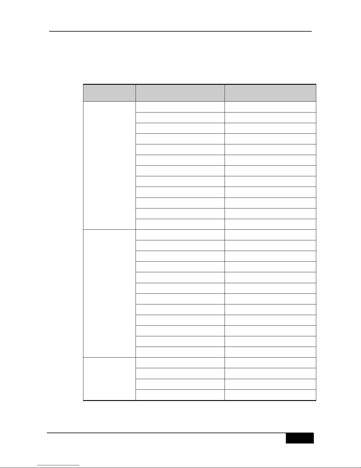
Table 1-1Technical specifications
DGS-8006 DGS-8010
Slot 6 (two slots for management
engine modules)
10 (two slots for management engine
modules)
Module type 8000-CM1
8000-24SC2XG-E
8000-24SC-E
8000-24TC-E
8000-48TC-E
8000-48PC-E
8000-4XG-E
8000-CM1
8000-24SC2XG-E
8000-24SC-E
8000-24TC-E
8000-48TC-E
8000-48PC-E
8000-4XG-E
Hot
swappable
Supported
Management
redundancy
Supported
Power supply/Fan
Power
supply
8000-1400AC: 90~176V~, power: 530W ; 176~264V~, power: 1400W
8000-2000AC: 90~176V~, power: 1080W ; 176~264V~, power:2000W

Chapter 1 Product Overview DGS-8000 Series Hardware Installation Guide
2
Power
supply
redundancy
Supported(must be the same type)
Fan 8006-FAN 8010-FAN
Environment
EMC
GB9254-1998 CLASS A,FCC CLASS A
Safety
regulation
GB4943-2001
Operating
temperature
0 to 50°C
Storage
temperature
-40 to 70°C
Operating
humidity
10% to 90% RH
Weight (Weight of the fans and empty chassis)
Weight
(chassis+fan
)
Net weight: 32.8KG Net weight: 44.3KG
Dimension
Dimension (L
x W x H) mm
437 x 500 x 486.15,11RU 437 x 450 x 930.65,21RU
Warning
DGS-8000 is a class A product. In a domestic environment this product may
cause radio interference in which case the user may be required to take
adequate measures.
There is more than one power input. Be sure that all power cables are pulled
out before you power down the system
Warning
Make sure that the blank panels are installed in the slots without the line cards
or management boards inserted for the purpose of heat dissipation.
Note
FCC Statement
:This equipment has been tested and found to comply with the
limits for a Class A digital device, pursuant to part 15 of the FCC Rules. These
limits are designed to provide reasonable protection against harmful
interference when the equipment is operated in a commercial environment.
This equipment generates, uses, and can radiate radio frequency energy and,
if not installed and used in accordance with the instruction manual, may cause
harmful interference to radio communications. Operation of this equipment in
a residential area is likely to cause harmful interference in which case the
user will be required to correct the interference at his own expense.
MODIFICATION: Any changes or modifications not expressly approved by the
grantee of this device could void the user’s authority to operate the device.
DGS-8000 Series Hardware Installation Guide Chapter 1 Product Overview
3
The 100Base-FX/1000Base-X SFP fiber ports of partial DGS-8000’s linecards and the
corresponding 10/100/1000Base-T copper ports are fiber/copper combo ports. That is, only
one port (fiber port or copper port) can be used at the same time. By default, the copper port
has the priority to be used. Table 1-2 shows the fiber/copper combo ports.
Table 1-2Corresponding relationship between two ports forming the fiber/copper combo ports
Product model 100BASE-FX /1000Base-X SFP
Fiber port
10/100/1000Base-T Adaptive
Ethernet port
1F 1
2F 2
3F 3
4F 4
5F 5
6F 6
7F 7
8F 8
9F 9
10F 10
11F 11
8000-24SC2XG-E
8000-24SC-E
12F 12
13F 13
14F 14
15F 15
16F 16
17F 17
18F 18
19F 19
20F 20
21F 21
22F 22
23F 23
8000-24TC-E
24F 24
45F 45
46F 46
47F 47
8000-48TC-E
8000-48PC-E
48F 48

Chapter 1 Product Overview DGS-8000 Series Hardware Installation Guide
4
1.3 DGS-8000 Switch System
1.3.1 Product Appearance
1.3.1.1 Appearance of DGS-8006
DGS-8006 hardware system consists of chassis, power supply system, system modules and
heat dissipation system.
Power supply system provides two slots for the power and supports 1+1 power redundancy.
It is recommanded to configure the redundancy for the power supply.
System module provides two slots for management modules, four slots service modules.
The management modules support 1+1 redundancy. It is recommanded to configure the
redundancy for management modules. You can choose the service module according to the
actual application requirements.
Heat dissipation system consists of fan tray and air filter. The fan tray is on the back of
chassis, and the air filters are on the two sides of chassis.
Figure 1-1 Appearance of DGS-8006

DGS-8000 Series Hardware Installation Guide Chapter 1 Product Overview
5
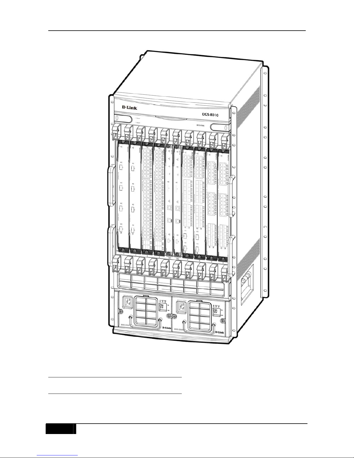
1.3.1.2 Appearance of DGS-8010
DGS-8010 hardware system consists of chassis, power supply system, system modules and
heat dissipation system.
Power supply system provides two slots for the power and supports 1+1 power redundancy.
It is recommanded to configure the redundancy for the power supply.
System module provides two slots for management modules, eight slots for service modules.
The management modules support 1+1 redundancy. It is recommanded to configure the
redundancy for management modules. You can choose the service module according to the
actual application requirements.
Heat dissipation system consists of fan tray and air filter. The fan tray is above the chassis,
and the air filter is below the chassis.
Chapter 1 Product Overview DGS-8000 Series Hardware Installation Guide
6
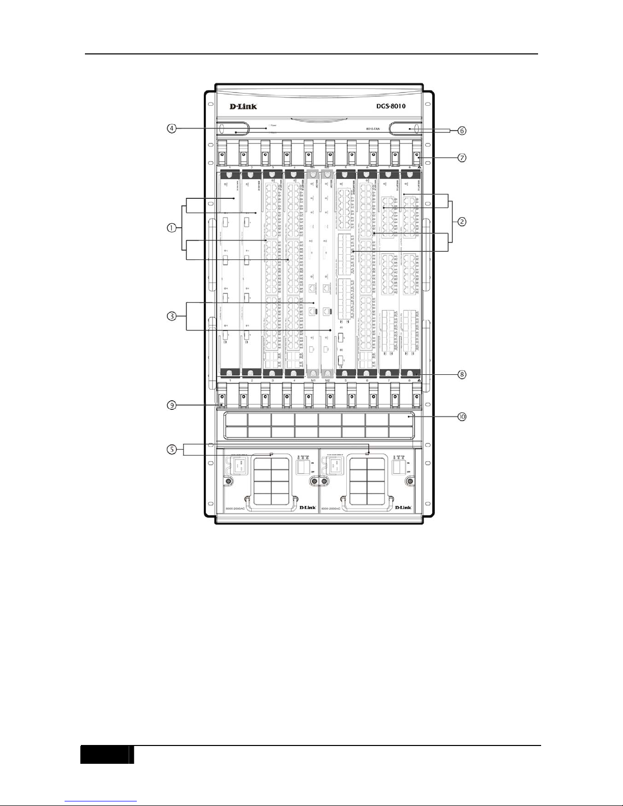
Figure 1-2 Appearance of DGS-8010
1.3.2 Front panel
1.3.2.1 Front panel of DGS-8006
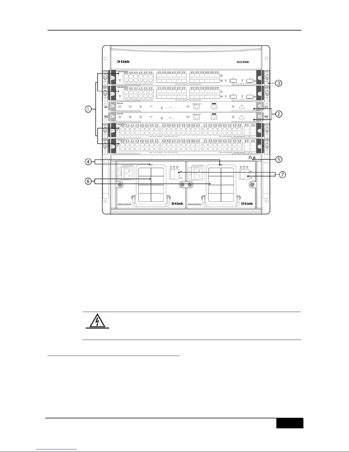
Figure 1-3 shows the schematic diagram of DGS-8006 front panel.
DGS-8000 Series Hardware Installation Guide Chapter 1 Product Overview
7
Figure 1-3
○1 Slots for service modules;
○2 Slots for management modules;
○3 Wiring rack;
○4 System power module installation location;
○5 Anti-static wrist strap hole;
○6 Plastic dust cap of the power module;
○7 System power module switch;
Warning
Before moving or transporting the DGS-8006 chassis, all management
modules、service modules and the power modules must be unplugged from
the chassis. Moving/Transporting the DGS-8006 device with the management
modules or service modules or power modules inserted is prohibited.
1.3.2.2 Front panel of DGS-8010
Figure 1-4 shows the schematic diagram of DGS-8010 front panel.
Chapter 1 Product Overview DGS-8000 Series Hardware Installation Guide
8
Figure 1-4
○1 Slots for service modules;
○2 Slots for service modules;
○3 Slots for management modules;
○4 Fan tray;
○5 System power module installation location;
○6 Fan tray handle;
○7 Wiring rack;
○8 Anti-static wrist strap hole;
DGS-8000 Series Hardware Installation Guide Chapter 1 Product Overview
9
○9 Wiring rack;
⑩ Dust prevention air-inlet plastic panel
Warning
Before moving or transporting the DGS-8010 chassis, all management
modules、service modules and the power modules must be unplugged from
the chassis. Moving/Transporting the DGS-8010 device with the management
modules or service modules or power modules inserted is prohibited.
1.3.3 Back panel
1.3.3.1 Back panel of DGS-8006
Figure 1-5 shows the schematic diagram of DGS-8006 back panel.
Figure 1-5
○1 Air fiter installation direction sign;
○2 Air filter;
○3 Captive screws on the air filter;
○4 Grounding point;
○5 Grounding point;
Chapter 1 Product Overview DGS-8000 Series Hardware Installation Guide
10
○6 Fan tray;
○7 Fan tray handle;
○8 Captive screws on the fan tray;
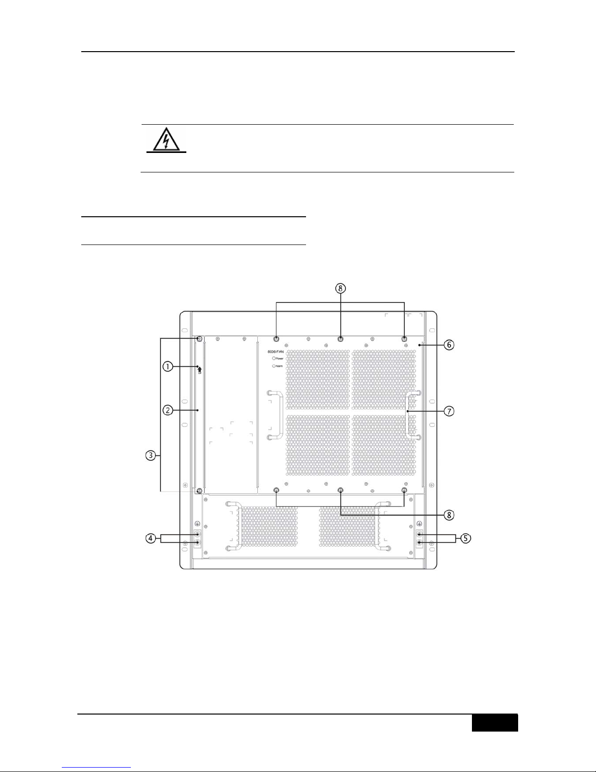
1.3.3.2 Back panel of DGS-8010
Figure 1-6 shows the schematic diagram of DGS-8010 back panel.
Figure 1-6
○1 Grounding point;
○2 Grounding point;
DGS-8000 Series Hardware Installation Guide Chapter 1 Product Overview
11
1.3.4 Power system
DGS-8000 series Ethernet switch uses the AC power input. Currently the 8000-1400AC and
8000-2000AC power modules are provided for this switch. The two power modules support
the power management. The management engine of DGS-8000 can read the power
information and realize the flexible and intelligent management for the whole switch’s power
through the power management policy. The technical specifications of
8000-1400AC/8000-2000AC module are shown below:
AC input:
Rated voltage range: 100~120V~, 200-240V~; 50/60Hz
Maximum voltage range: 90~264V~; 47~63Hz
Maximum output power: 8000-1400AC: 90~176V~ Power:530W
176~264V~ Power:1400W
8000-2000AC: 90~176V~ Power:1080W
176~264V~ Power:2000W
Note
DGS-8006/8010 series switch supports the 1+1 redundancy of power supply.
In order to improve the stability and reliability for the overall system’s
operation, you are recommended to configure the 1+1 redundancy for the
power module of DGS-8006/8010.
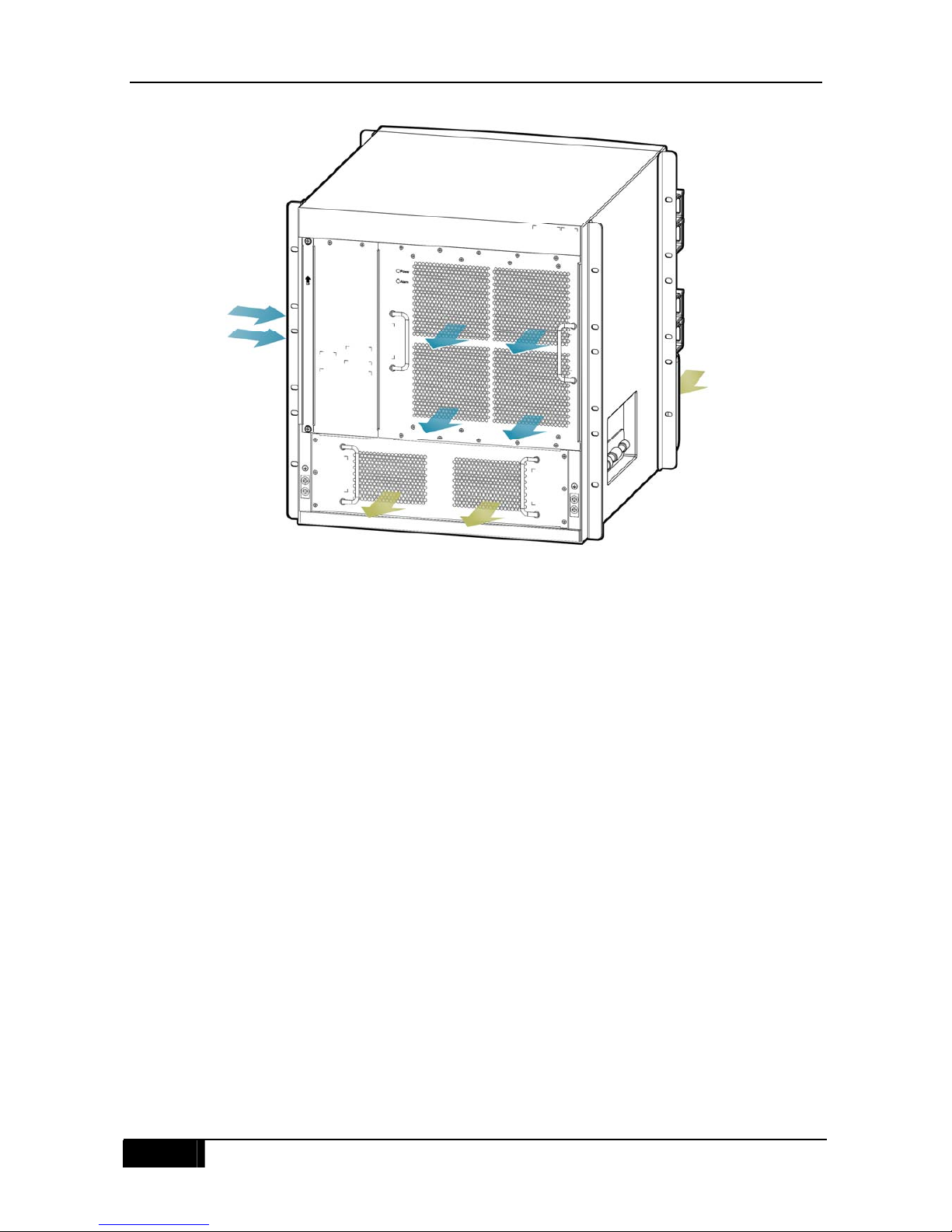
1.3.5 Heat Dissipation System
The operating temperature of DGS-8000 is 0 to 50°C. The thermal design must ensure that
the switch works at such an ambient temperature for high reliability, security, and reparability.
According to the thermal design of DGS-8000, fans are used to induct air for a forced
convection in order to ensure that the equipment works in the specified environment well.
Figure 1-7 and Figure 1-8 show the flow scheme of heat dissipation of DGS-8006/8010,
respectively.
Chapter 1 Product Overview DGS-8000 Series Hardware Installation Guide
12
Figure 1-7 DGS-8006 heat dissipation system
Note: The structure of host management module and service module is designed with air
inlet on right side, and air outlet at back. And the power module is designed with air inlet at
front, and air outlet at back. Isolation boards are provided among host management modules,
service modules and power modules to isolate the two air passages. 4PCS 120*120*38 fans
are used to blow air outside for convection and ultimately heat dissipation. Therefore, the
chassis should be mounted at a place with sufficient space for air circulation.

DGS-8000 Series Hardware Installation Guide Chapter 1 Product Overview
13
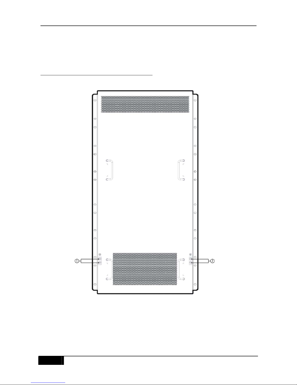
Figure 1-8 DGS-8010 heat dissipation system
Note: This structure of host management module and service module is designed with air
inlet at front and two sides, and air outlet at top back and both sides. And the power module
is designed with air inlet at front, and air outlet at back. Isolation boards are provided among
host management modules, service modules and power modules to isolate the two air
passages. 6PCS 120*120*38 fans are used to blow air outside for convection and ultimately
heat dissipation. Therefore, the chassis should be mounted at a place with sufficient space
for air circulation.
1.4 Modules
The DGS-8000 Series Ethernet Switches adopt modular design. In strict accordance with
industry standards, reasonably segmented system modules and unified module interfaces
ensure that the DGS-8000 Series Ethernet Switches have complete and reasonable
systems and that functional modules are independent. At present, the DGS-8000 Series
Ethernet Switches provide 10/100/1000M adaptive Ethernet copper interfaces, 1000/100M
SFP (single-mode/multimode) fiber interfaces, and 10G fiber interfaces. The following
sections describe the specifications and performance of service modules in detail.
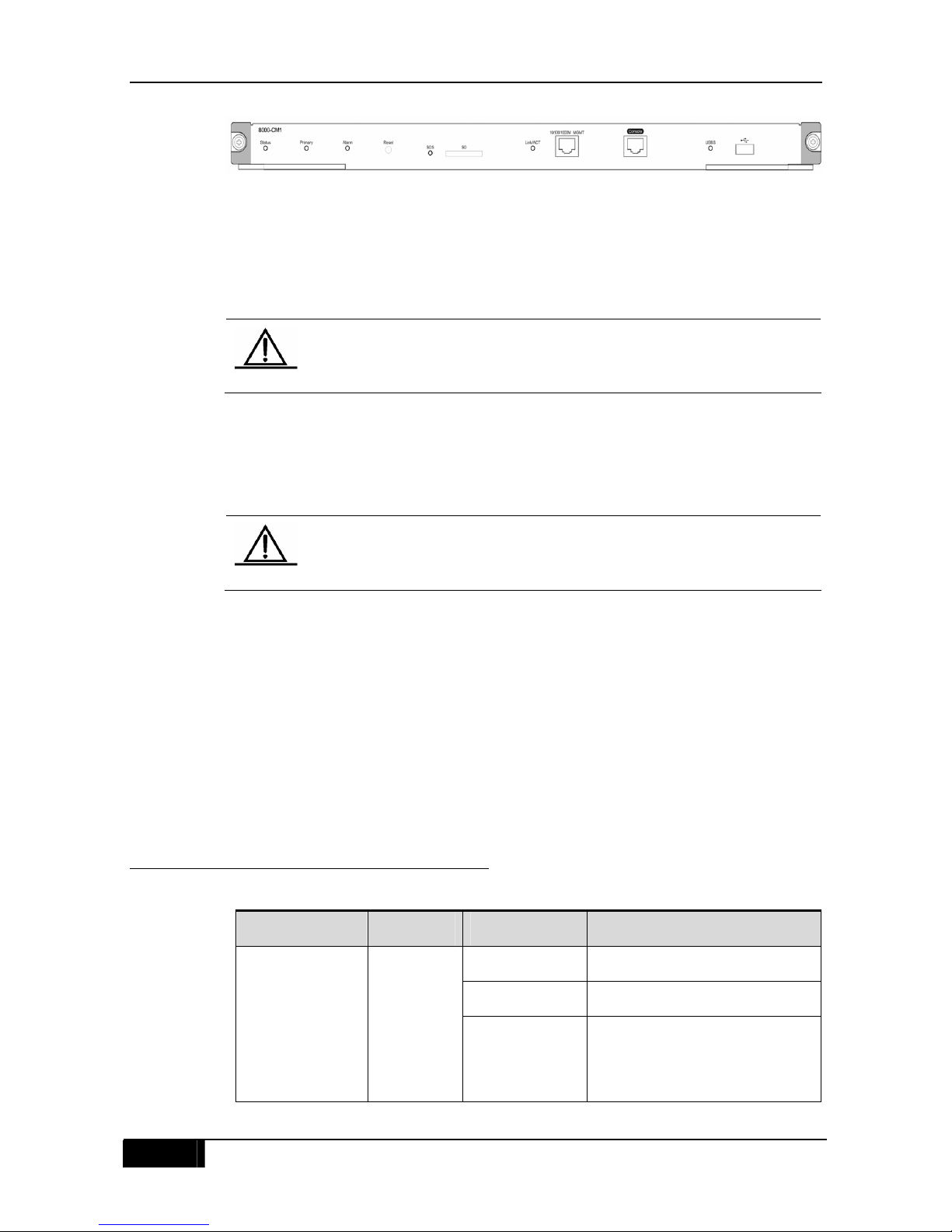
1.4.1 8000-CM1 Module
1.4.1.1 Introduction
As the management engine module of the DGS-8000 series Ethernet switch, the 8000-CM1
module provides management and switching functions for the switch. The 8000-CM1
module provides a Console port, a 10/100/1000M MGMT port, a USB port, an SD card port,
and a Reset button. Figure 1-9 shows the appearance of the 8000-CM1.
Chapter 1 Product Overview DGS-8000 Series Hardware Installation Guide
14
Figure 1-9 8000-CM1 appearance
The 8000-CM1 module provides five external ports:
Universal Serial Bus (USB) port: This port can be connected to a USB storage that is
used to store logs, host versions, alarms and other diagnosis information, facilitating
online upgrade of switch software and saving of log information.
Note
To ensure data security and prevent device damage, you should select USB
flash memory of good brand and high quality. In addition, the USB port can be
compatible with most USB controllers but may fail to identify USB flash
memory of certain models.
Secure Digital Memory Card (SD) port: This port can be connected to an SD storage
that is used to store logs, host versions, alarms and other diagnosis information,
facilitating online upgrade of switch software and saving of log information.
Note
To ensure data security and prevent device damage, you should select SD
storages of good brand and high quality. In addition, the SD port can be
compatible with most SD storages but may fail to identify SD storages of
certain models.
Console port: or communication serial port, which uses RS-232 level and standard
RJ-45 connector. This port is used to connect to the serial port of a background terminal
computer to conduct debugging, configuration, maintenance, and management of a
system and loading of host software programs.
10/100/1000M MGMT port: or 10/100/1000BASE-T Ethernet port, which uses the RJ-45
connector. This port can be used to connect to the Ethernet port of a background
computer to load programs. Standard network cables can be used for connecting to the
Ethernet port of a background computer.
Reset button: or system reset button, which can reset the system.
1.4.1.2 LEDs on the Module Panel
Table 1-3 LEDs on the front panel
LED Identifier Status Meaning
Off The module is not powered on.
Solid Red The module is abnormal.
System LED Status
Blinking Green The module is being initialized. If
the LED blinks all the time, it
indicates that the module is
abnormal.

DGS-8000 Series Hardware Installation Guide Chapter 1 Product Overview
15
Solid Green The initialization of the module is
complete, and switching can be
performed normally.
Off The module is a secondary
management engine module.
Primary/Seconda
ry MGMT engine
LED
Primary
Solid Green The module is a primary
management engine module.
Off No fault
Solid Red System fault, which causes the
system or a module to be unable
to continue running or causes
device damages if the system or
a module continues to run
Fault alarm LED Alarm
Solid Yellow The temperature exceeds the
alarm temperature, which affects
system running performance, but
the system can continue to run.
Off There is no link Up.
Green The link is Up at 1000Mbps.
Yellow The link is Up at 10Mbps or
100Mbps.
MGMT port LED Link/ACT
Blinking There is data received or sent on
the port.
Off No SD card is inserted into the
port or the SD card is not loaded
successfully.
Solid Green The SD card is loaded
successfully.
SD port LED SDS
Blinking Green The SD card is being read and
written.
Off No USB flash memory is inserted
into the port or the USB flash
memory is not loaded
successfully.
Solid Green The USB flash memory is loaded
successfully.
USB port LED USBS
Blinking Green The USB flash memory is being
read and written.
Chapter 1 Product Overview DGS-8000 Series Hardware Installation Guide
16
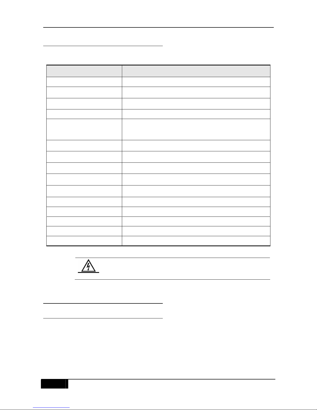
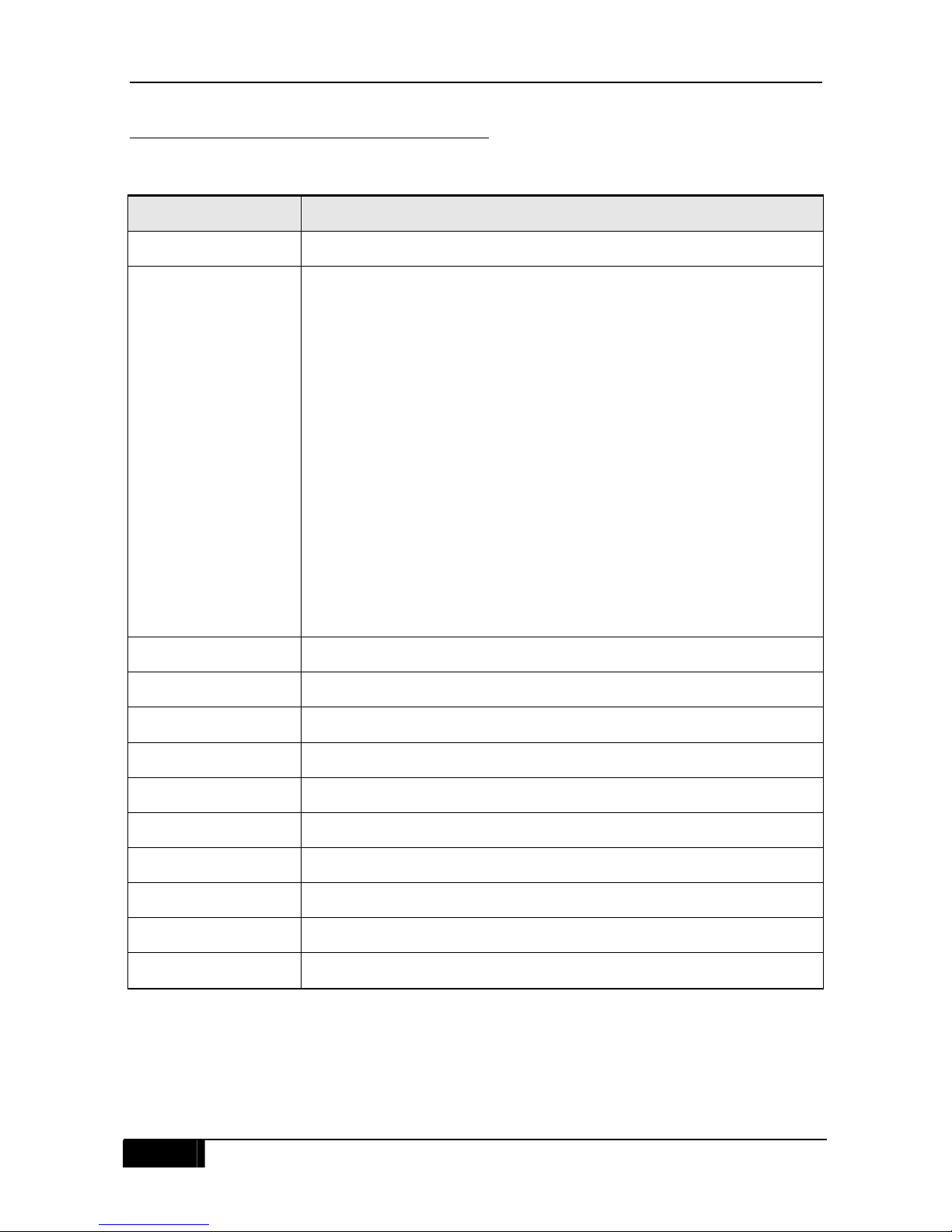
1.4.1.3 Technical Specifications
Table 1-4 8000-CM1 technical specifications
Warning
Risk of explosion if battery is replaced by an incorrect type. Batter type
CR2032 is used in the 8000-CM1. Dispose of used batteries according to
the instructions.
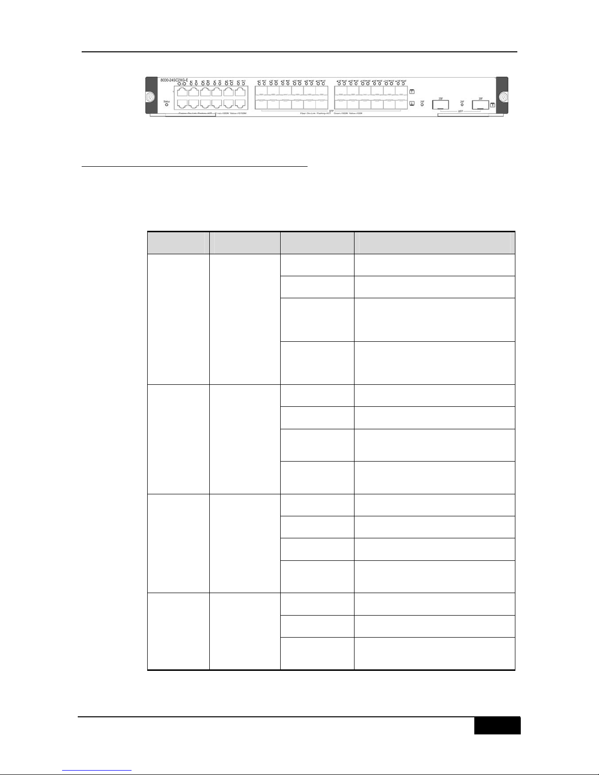
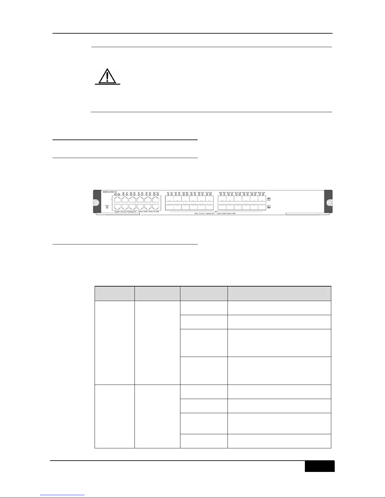
1.4.2 8000-24SC2XG-E Module
1.4.2.1 Introduction
Figure 1-10 shows the appearance of the 8000-24SC2XG-E module. This module provides
two 10G XFP ports, 12 pure SFP ports, and 12 fiber/copper combo ports. SFP ports support
100/1000M rate , and RJ-45 ports support 10/100/1000M autonegotiation. XFP and SFP
optical modules support hot swap.
Product Model 8000-CM1
CPU 800MHz
BOOTROM 8MB
Flash Memory 512MB
SDRAM 2GB
External ports
One Console port, one 10/100/1000M MGMT port, one USB port,
one SD card port, and one Reset button
Power consumption <91W
Hot swap Supported
Management redundancy Supported
EMC
GB9254-1998 Class A; FCC Class A
Safety
GB4943-2001
Operating temperature 0 to 50°C
Storage temperature -40 to 70°C
Operating humidity 10% to 90% RH
Weight 2.8kg (net)
Dimensions (L x W x H) 436 x 346 x 30 mm
DGS-8000 Series Hardware Installation Guide Chapter 1 Product Overview
17
Figure 1-10 8000-24SC2XG-E appearance
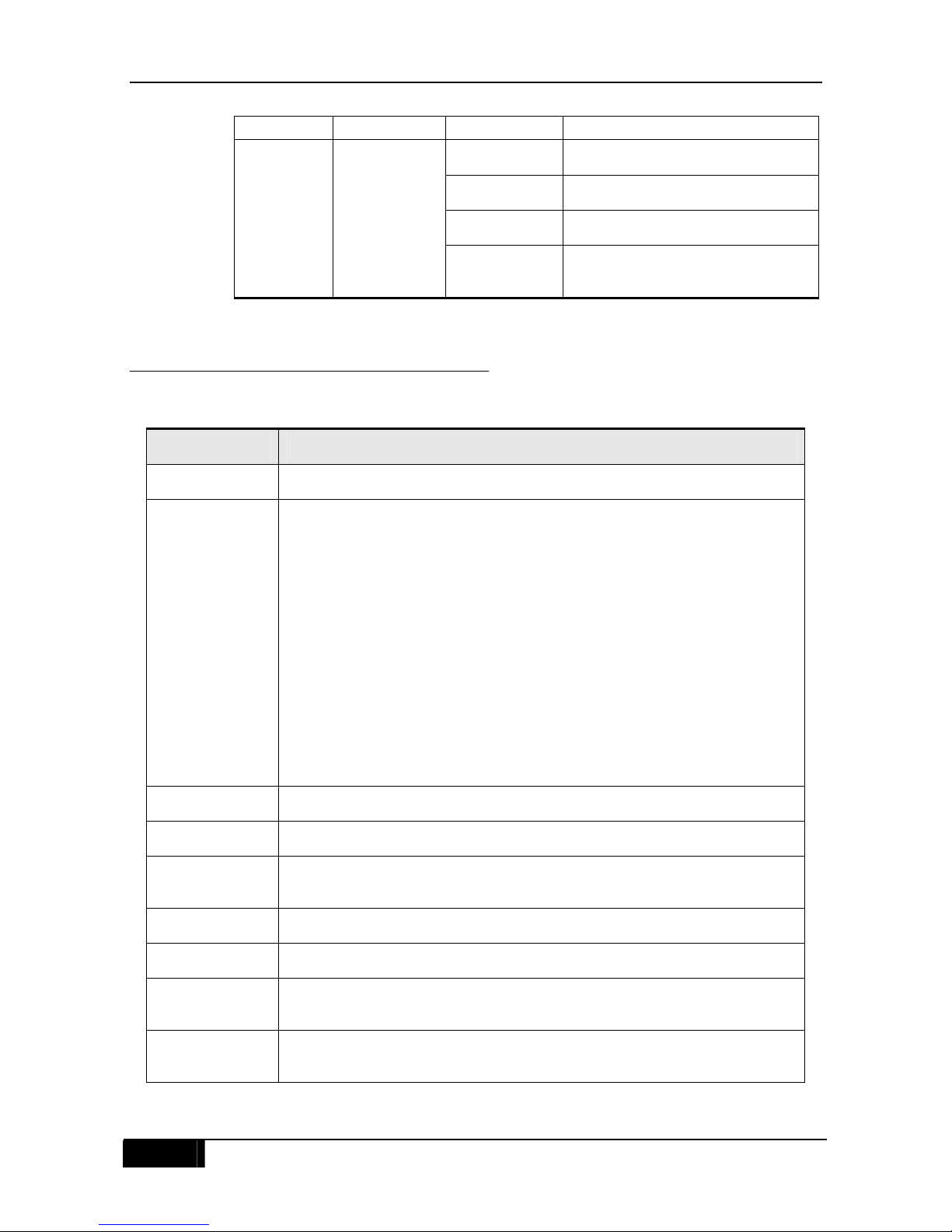
1.4.2.2 LEDs on the Module Panel
The 8000-24SC2XG-E module provides LEDs indicating system states. The Status LED
indicates the operating status of a board itself, and each port provides a Link/ACT LED to
indicate the operating status of the port itself. Table 1-5 shows their detailed meanings.
Table 1-5 LEDs on the front panel
LED Identifier Status Meaning
Off The module is not powered on.
Solid Red The module is abnormal.
Blinking Green The module is being initialized. If the
LED blinks all the time, it indicates
that the module is abnormal.
System LED Status
Solid Green The initialization of the module is
complete, and switching can be
performed normally.
Off There is no link Up.
Solid Green The link is Up at 1000Mbps.
Solid Yellow The link is Up at 10Mbps or
100Mbps.
RJ-45 port
LED
Link/ACT
Blinking There is data received or sent on the
port.
Off There is no link Up.
Solid Green The link is Up at 1000Mbps.
Solid Yellow The link is Up at 100Mbps.
SFP port
LED
Link/ACT
Blinking There is data received or sent on the
port.
Off There is no link Up.
Solid Green The link is Up at 10Mbps.
XFP port
LED
Link/ACT
Blinking There is data received or sent on the
port.
Chapter 1 Product Overview DGS-8000 Series Hardware Installation Guide
18
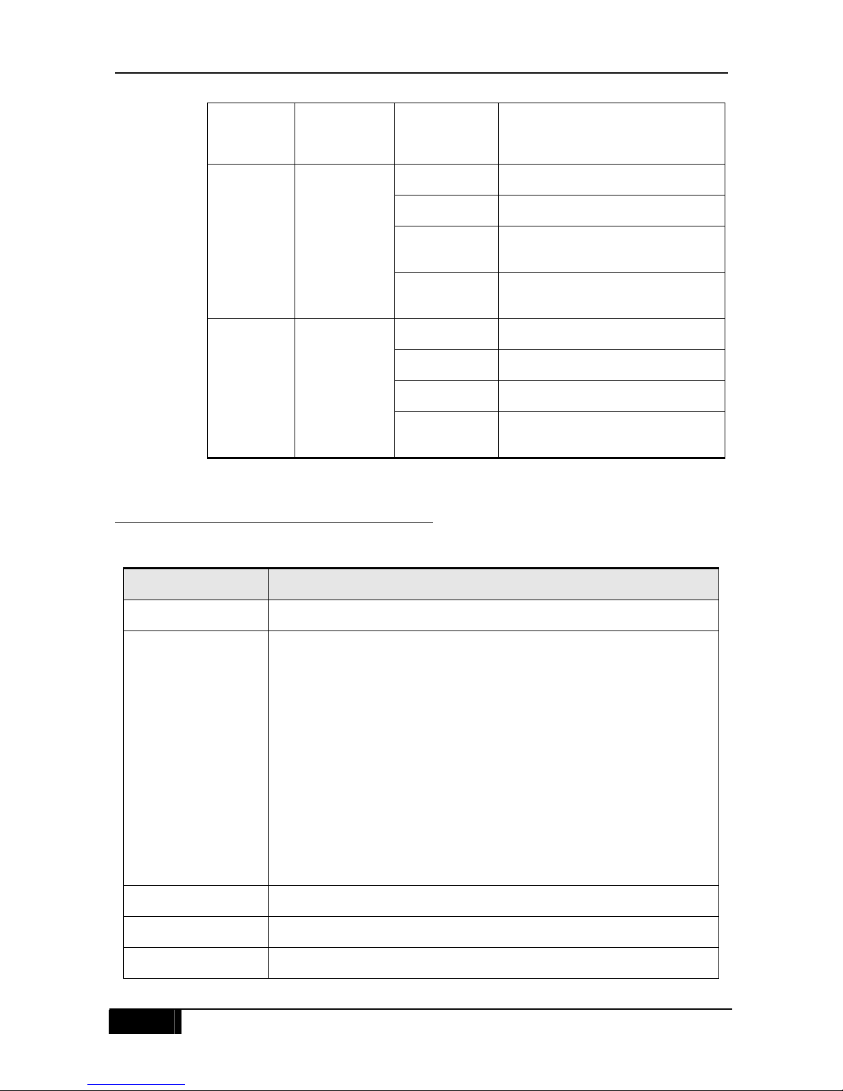
1.4.2.3 Technical Specifications
Table 1-6 8000-24SC2XG-E technical specifications
Product Model 8000-24SC2XG-E
Ports Two 10G XFP ports, 12 pure SFP ports, and 12 fiber/copper combo ports
Fiber Transceiver
supported
Supported SFP Transceivers:
1. DEM-210 (100Base-FX, Multi-mode, 2km)
2. DEM-211 (100Base-FX, Single-mode, 15km)
3. DEM-310GT (1000Base-LX, Single-mode, 10km)
4. DEM-311GT (1000ase-SX, Mutli-mode, 500m)
5. DEM-312GT2 (1000Base-SX, Multi-mode, 2km)
6. DEM-314GT (1000BASE-LX, Single-mode, 50km)
7. DEM-315GT (1000BASE-LX, Single-mode, 80km)
8. DGS-712 (1000Base-T)
Supported SFP WDM transceivers:
1. DEM-220T (100Base-FX, Single-mode, 20km, TX-1550/RX-1310nm)
2. DEM-220R (100Base-FX, Single-mode, 20km, TX-1310/RX-1550nm)
3. DEM-330T (1000Base-LX, Single-mode, 10km, TX-1550/RX-1310nm)
4. DEM-330R (1000Base-LX, Single-mode, 10km, TX-1310/RX-1550nm)
5. DEM-331T (1000Base-LX, Single-mode, 40km, TX-1550/RX-1310nm)
6. DEM-331R (1000Base-LX, Single-mode, 40km, TX-1310/RX-1550nm)
Supported XFP Transceivers :
1. DEM-421XT (10GBase-SR, Multi-mode, 300m)
2. DEM-422XT (10GBase-LR, Single-mode, 10km)
3. DEM-423XT (10GBase-ER, Single-mode, 40km)
LED Status, Link/ACT
Hot swap Supported
Power consumption <100W
EMC GB9254-1998 Class A; FCC Class A
Safety GB4943-2001
Operating temperature 0 to 50°C
Storage temperature -40 to 70°C
Operating humidity 10% to 90% RH
Weight 3.3kg (net)
Dimensions (L x W x H) 436 x 346 x 45 mm
DGS-8000 Series Hardware Installation Guide Chapter 1 Product Overview
19
Note
1. The first 12 ports of the 8000-24SC2XG-E module are fiber/copper
combo ports. That is, each SFP port corresponds to a combo
10/100/1000BASE-T port, and only one port can be used at a time, with
the other being unavailable. The automatic MDI/MDI-X identification of
10/100/1000BASE-T copper ports is effective only when auto-negotiation
is enabled.
2. The 8000-24SC2XG-E module supports 1000BASE-X and
100BASE-FX. You should configure the ports as desired operating
modes according to the Configuration Guide
1.4.3 8000-24SC-E Module
1.4.3.1 Introduction
Figure 1-11 shows the appearance of the 8000-24SC-E module. This module provides 12
pure SFP ports, and 12 fiber/copper combo ports. SFP ports support 100/1000M rate, and
RJ-45 ports support 10/100/1000M autonegotiation. SFP optical modules support hot swap.
Figure 1-11 8000-24SC-E appearance
1.4.3.2 LEDs on the Module Panel
The 8000-24SC-E module provides LEDs indicating system states. The Status LED
indicates the operating status of a board itself, and each port provides a Link/ACT LED to
indicate the operating status of the port itself. Table 1-7 shows their detailed meanings.
Table 1-7 LEDs on the front panel
LED Identifier Status Meaning
Off The module is not powered on.
Solid Red The module is abnormal.
Blinking Green The module is being initialized. If the
LED blinks all the time, it indicates
that the module is abnormal.
System LED Status
Solid Green The initialization of the module is
complete, and switching can be
performed normally.
Off There is no link Up.
Solid Green The link is Up at 1000Mbps.
Solid Yellow The link is Up at 10Mbps or
100Mbps.
RJ-45 port
LED
Link/ACT
Blinking There is data received or sent on the
Chapter 1 Product Overview DGS-8000 Series Hardware Installation Guide
20
port.
Off There is no link Up.
Solid Green The link is Up at 1000Mbps.
Solid Yellow The link is Up at 100Mbps.
SFP port
LED
Link/ACT
Blinking There is data received or sent on the
port.
1.4.3.3 Technical Specifications
Table 1-8 8000-24SC-E technical specifications
Product Model 8000-24SC-E
Ports 12 pure SFP ports and 12 fiber/copper combo ports
Fiber Transceiver
supported
Supported SFP Transceivers:
1. DEM-210 (100Base-FX, Multi-mode, 2km)
2. DEM-211 (100Base-FX, Single-mode, 15km)
3. DEM-310GT (1000Base-LX, Single-mode, 10km)
4. DEM-311GT (1000ase-SX, Mutli-mode, 500m)
5. DEM-312GT2 (1000Base-SX, Multi-mode, 2km)
6. DEM-314GT (1000BASE-LX, Single-mode, 50km)
7. DEM-315GT (1000BASE-LX, Single-mode, 80km)
8. DGS-712 (1000Base-T)
Supported SFP WDM transceivers:
1. DEM-220T (100Base-FX, Single-mode, 20km, TX-1550/RX-1310nm)
2. DEM-220R (100Base-FX, Single-mode, 20km, TX-1310/RX-1550nm)
3. DEM-330T (1000Base-LX, Single-mode, 10km, TX-1550/RX-1310nm)
4. DEM-330R (1000Base-LX, Single-mode, 10km, TX-1310/RX-1550nm)
5. DEM-331T (1000Base-LX, Single-mode, 40km, TX-1550/RX-1310nm)
6. DEM-331R (1000Base-LX, Single-mode, 40km, TX-1310/RX-1550nm)
LED Status, Link/ACT
Hot swap Supported
Power
consumption
<84W
EMC GB9254-1998 Class A; FCC Class A
Safety GB4943-2001
Operating
temperature
0 to 50°C
Storage
temperature
-40 to 70°C

DGS-8000 Series Hardware Installation Guide Chapter 1 Product Overview
21
Note
1. The first 12 ports of the 8000-24SC-E module are fiber/copper combo
ports. That is, each SFP port corresponds to a combo
10/100/1000BASE-T port, and only one port can be used at a time, with
the other being unavailable. The automatic MDI/MDI-X identification of
10/100/1000BASE-T copper ports is effective only when auto-negotiation
is enabled.
2. The 8000-24SC-E module supports 1000BASE-X and 100BASE-FX.
You should configure the ports as desired operating modes according to
the Configuration Guide
1.4.4 8000-48TC-E Module
1.4.4.1 Introduction
Figure 1-12 shows the appearance of the 8000-48TC-E module. This module provides 44
RJ-45 ports for 10/100/1000BASE-T and four fiber/copper combo ports. SFP ports support
100/1000M rate, and RJ-45 ports support 10/100/1000M autonegotiation. SFP optical
modules support hot swap.
Figure 1-12 8000-48TC-E appearance
1.4.4.2 LEDs on the Module Panel
The 8000-48TC-E module provides LEDs indicating system states. The Status LED
indicates the operating status of a board itself, and each port provides a Link/ACT LED to
indicate the operating status of the port itself. Table 1-9 shows their detailed meanings.
Table 1-9 LEDs on the front panel
LED Identifier Status Meaning
Off The module is not powered on.
Solid Red The module is abnormal.
System LED Status
Blinking green The module is being initialized. If the
LED blinks all the time, it indicates
that the module is abnormal.
Operating
humidity
10% to 90% RH
Weight 3.2kg (net)
Dimensions (L x
W x H)
436 x 346 x 45 mm
Chapter 1 Product Overview DGS-8000 Series Hardware Installation Guide
22
Solid Green The initialization of the module is
complete, and switching can be
performed normally.
Off There is no link Up.
Solid Green The link is Up at 1000Mbps.
Solid Yellow The link is Up at 10Mbps or
100Mbps.
RJ-45 port
LED
Link/ACT
Blinking There is data received or sent on the
port.
Off There is no link Up.
Solid Green The link is Up at 1000Mbps.
Solid Yellow The link is Up at 100Mbps.
SFP port
LED
Link/ACT
Blinking There is data received or sent on the
port.
1.4.4.3 Technical Specifications
Table 1-10 8000-48TC-E technical specifications
Product Model 8000-48TC-E
Ports 44 RJ-45 ports for 10/100/1000BASE-T and 4 fiber/copper combo ports
Fiber Transceiver
supported
Supported SFP Transceivers:
1. DEM-210 (100Base-FX, Multi-mode, 2km)
2. DEM-211 (100Base-FX, Single-mode, 15km)
3. DEM-310GT (1000Base-LX, Single-mode, 10km)
4. DEM-311GT (1000ase-SX, Mutli-mode, 500m)
5. DEM-312GT2 (1000Base-SX, Multi-mode, 2km)
6. DEM-314GT (1000BASE-LX, Single-mode, 50km)
7. DEM-315GT (1000BASE-LX, Single-mode, 80km)
8. DGS-712 (1000Base-T)
Supported SFP WDM transceivers:
1. DEM-220T (100Base-FX, Single-mode, 20km, TX-1550/RX-1310nm)
2. DEM-220R (100Base-FX, Single-mode, 20km, TX-1310/RX-1550nm)
3. DEM-330T (1000Base-LX, Single-mode, 10km, TX-1550/RX-1310nm)
4. DEM-330R (1000Base-LX, Single-mode, 10km, TX-1310/RX-1550nm)
5. DEM-331T (1000Base-LX, Single-mode, 40km, TX-1550/RX-1310nm)
6. DEM-331R (1000Base-LX, Single-mode, 40km, TX-1310/RX-1550nm)
LED Status, Link/ACT
Hot swap Supported
Power consumption <121W
DGS-8000 Series Hardware Installation Guide Chapter 1 Product Overview
23
Note
1. The last 4 ports of the 8000-48TC-E module are fiber/copper combo
ports. That is, each SFP port corresponds to a combo
10/100/1000BASE-T port, and only one port can be used at a time, with
the other being unavailable. The automatic MDI/MDI-X identification of
10/100/1000BASE-T copper ports is effective only when auto-negotiation
is enabled.
2. The 8000-48TC-E module supports 1000BASE-X and 100BASE-FX.
You should configure the ports as desired operating modes according to
the Configuration Guide
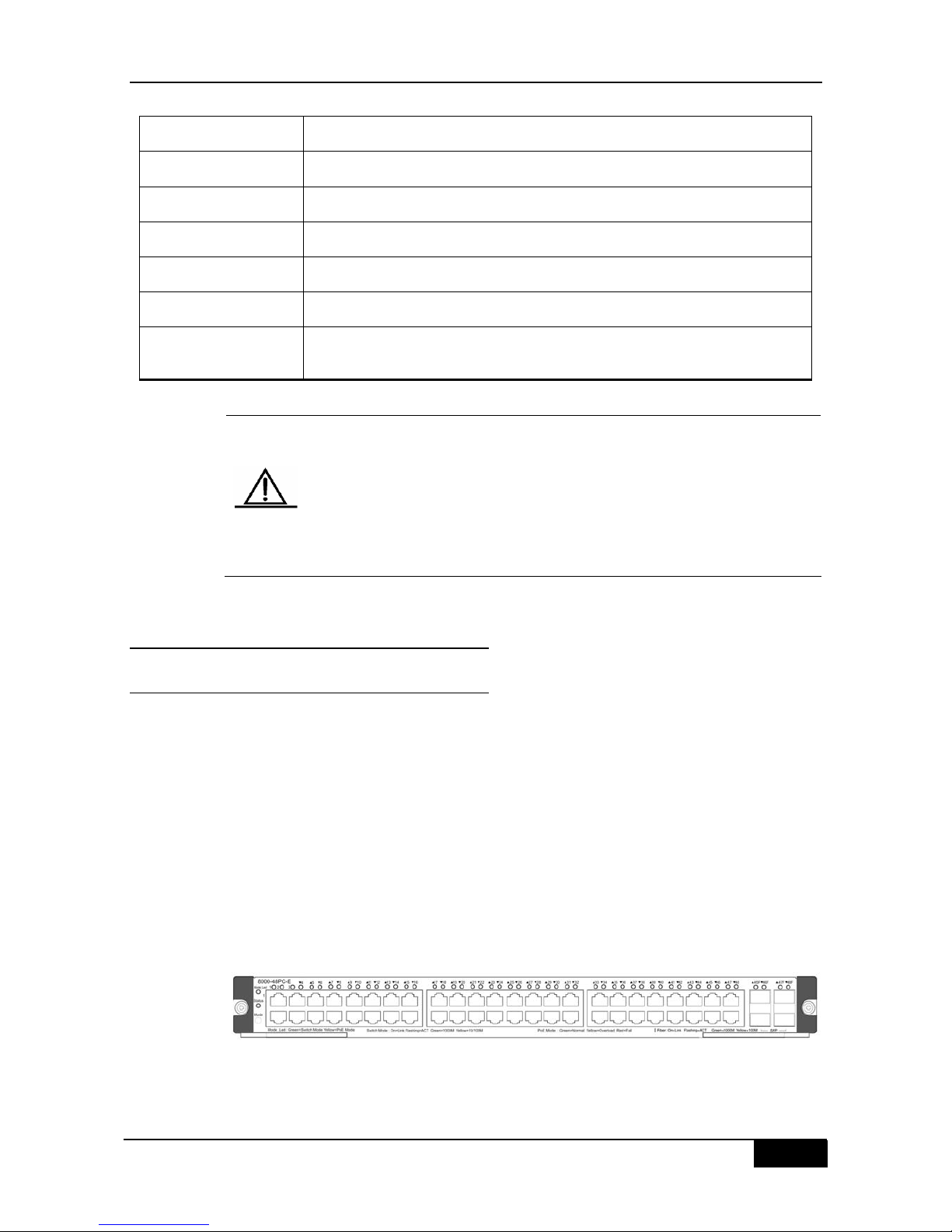
1.4.5 8000-48PC-E Module
1.4.5.1 Introduction
Figure 1-13 shows the appearance of the 8000-48PC-E module. This module provides 44
RJ-45 ports for 10/100/1000BASE-T, and four fiber/copper combo ports. SFP ports support
100/1000M rate, and RJ-45 ports support 10/100/1000M autonegotiation and the PoE
function. SFP optical modules support hot swap.
The functions of the Mode button is described as follows:
Press the “Mode” button, and the port LED indicates switchover between switching
mode and PoE mode upon releasing the button.
In PoE mode, if the PSE is supplying power to PDs, pressing the “Mode” button and
holding it for about three seconds causes the PSE to stop supplying power to PDs upon
releasing the button.
In PoE mode, if the PSE does not supply power to PDs, pressing the “Mode” button and
holding it for about three seconds makes the PSE begin supplying power to PDs upon
releasing the button.
Figure 13 8000-48PC-E appearance
EMC GB9254-1998 Class A; FCC Class A
Safety GB4943-2001
Operating temperature 0 to 50°C
Storage temperature -40 to 70°C
Operating humidity 10% to 90% RH
Weight 3.6kg (net)
Dimensions (L x W x
H)
436 x 346 x 45 mm
 Loading...