

D-Link DGS-3620-28SC-EI, DGS-3620-52P-SI, DGS-3620-28TC-SI, DGS-3620-52P-EI, DGS-3620-52T-EI Product Manual
...

xStack® DGS-3620 Series Managed Switch Web UI Reference Guide
i
Information in this document is subject to change without notice.
© 2011 D-Link Corporation. All rights reserved.
Reproduction of this document in any manner whatsoever without the written permission of D-Link Corporation is strictly forbidden.
Trademarks used in this text: D-Link and the D-LINK logo are trademarks of D-Link Corporation; Microsoft and Windows are registered
trademarks of Microsoft Corporation.
Other trademarks and trade names may be used in this document to refer to either the entities claiming the marks and names or their products.
D-Link Corporation disclaims any proprietary interest in trademarks and trade names other than its own.
February 2011 P/N 651GS3620015G

xStack® DGS-3620 Series Managed Switch Web UI Reference Guide
ii
Table of Contents
Intended Readers ............................................................................................................................................................ 1
Typographical Conventions ............................................................................................................................................. 1
Notes, Notices and Cautions........................................................................................................................................... 1
Safety Instructions ........................................................................................................................................................... 1
Safety Cautions ........................................................................................................................................................... 2
General Precautions for Rack-Mountable Products........................................................................................................ 3
Protecting Against Electrostatic Discharge ..................................................................................................................... 4
Chapter 1 Web-based Switch Configuration ........................................................................... 5
Introduction ...................................................................................................................................................................... 5
Login to the Web Manager .............................................................................................................................................. 5
Web-based User Interface .............................................................................................................................................. 6
Areas of the User Interface.......................................................................................................................................... 6
Web Pages ...................................................................................................................................................................... 7
Chapter 2 System Configuration .............................................................................................. 8
Device Information .......................................................................................................................................................... 8
System Information Settings ........................................................................................................................................... 9
Port Configuration ......................................................................................................................................................... 10
Port Settings .............................................................................................................................................................. 10
Port Description Settings ........................................................................................................................................... 11
Port Error Disabled .................................................................................................................................................... 12
Port Auto Negotiation Information ............................................................................................................................. 13
Jumbo Frame Settings .............................................................................................................................................. 14
PoE ................................................................................................................................................................................ 14
PoE System Settings ................................................................................................................................................. 15
PoE Port Settings ...................................................................................................................................................... 16
Serial Port Settings ....................................................................................................................................................... 17
Warning Temperature Settings ..................................................................................................................................... 17
System Log configuration .............................................................................................................................................. 18
System Log Settings .................................................................................................................................................. 18
System Log Server Settings ...................................................................................................................................... 18
System Log ................................................................................................................................................................ 19
System Log & Trap Settings ...................................................................................................................................... 20
System Severity Settings ........................................................................................................................................... 21
Time Range Settings ..................................................................................................................................................... 21
Port Group Settings ....................................................................................................................................................... 22
Time Settings ................................................................................................................................................................ 22
User Accounts Settings ................................................................................................................................................. 23
Command Logging Settings .......................................................................................................................................... 24
Stacking ......................................................................................................................................................................... 24
Stacking Device Table ............................................................................................................................................... 26
Stacking Mode Settings ............................................................................................................................................. 26
Chapter 3 Management ........................................................................................................... 28
ARP ............................................................................................................................................................................... 28
Static ARP Settings ................................................................................................................................................... 28
Proxy ARP Settings ................................................................................................................................................... 29
ARP Table ................................................................................................................................................................. 29
Gratuitous ARP ............................................................................................................................................................. 30

xStack® DGS-3620 Series Managed Switch Web UI Reference Guide
iii
Gratuitous ARP Global Settings ................................................................................................................................ 30
Gratuitous ARP Settings ............................................................................................................................................ 30
IPv6 Neighbor Settings ................................................................................................................................................. 31
IP Interface .................................................................................................................................................................... 32
System IP Address Settings ...................................................................................................................................... 32
Interface Settings ....................................................................................................................................................... 33
Loopback Interface Settings ...................................................................................................................................... 37
Management Settings ................................................................................................................................................... 38
Out of Band Management Settings ............................................................................................................................... 39
Session Table................................................................................................................................................................ 39
Single IP Management .................................................................................................................................................. 40
Single IP Settings ...................................................................................................................................................... 41
Topology .................................................................................................................................................................... 42
Firmware Upgrade ..................................................................................................................................................... 48
Configuration File Backup/Restore ............................................................................................................................ 49
Upload Log File ......................................................................................................................................................... 49
SNMP Settings .............................................................................................................................................................. 49
SNMP Global Settings ............................................................................................................................................... 50
SNMP Traps Settings ................................................................................................................................................ 51
SNMP Linkchange Traps Settings ............................................................................................................................ 51
SNMP View Table Settings ....................................................................................................................................... 52
SNMP Community Table Settings ............................................................................................................................. 53
SNMP Group Table Settings ..................................................................................................................................... 54
SNMP Engine ID Settings ......................................................................................................................................... 55
SNMP User Table Settings........................................................................................................................................ 55
SNMP Host Table Settings ........................................................................................................................................ 56
SNMPv6 Host Table Settings .................................................................................................................................... 57
RMON Settings .......................................................................................................................................................... 58
SNMP Community Encryption Settings ..................................................................................................................... 58
SNMP Community Masking Settings ........................................................................................................................ 58
Telnet Settings .............................................................................................................................................................. 59
Web Settings ................................................................................................................................................................. 59
Chapter 4 L2 Features ............................................................................................................. 61
VLAN ............................................................................................................................................................................. 61
802.1Q VLAN Settings .............................................................................................................................................. 66
802.1v Protocol VLAN ............................................................................................................................................... 69
Asymmetric VLAN Settings ....................................................................................................................................... 71
GVRP ......................................................................................................................................................................... 71
MAC-based VLAN Settings ....................................................................................................................................... 73
Private VLAN Settings ............................................................................................................................................... 73
PVID Auto Assign Settings ........................................................................................................................................ 75
Subnet VLAN ............................................................................................................................................................. 75
Super VLAN ............................................................................................................................................................... 77
Voice VLAN ............................................................................................................................................................... 79
VLAN Trunk Settings ................................................................................................................................................. 82
Browse VLAN ............................................................................................................................................................ 83
Show VLAN Ports ...................................................................................................................................................... 83
QinQ .............................................................................................................................................................................. 83
QinQ Settings ............................................................................................................................................................ 85
VLAN Translation Settings ........................................................................................................................................ 86

xStack® DGS-3620 Series Managed Switch Web UI Reference Guide
iv
Layer 2 Protocol Tunneling Settings ............................................................................................................................. 87
Spanning Tree ............................................................................................................................................................... 87
STP Bridge Global Settings ....................................................................................................................................... 89
STP Port Settings ...................................................................................................................................................... 91
MST Configuration Identification ............................................................................................................................... 92
STP Instance Settings ............................................................................................................................................... 93
MSTP Port Information .............................................................................................................................................. 93
Link Aggregation ........................................................................................................................................................... 94
Port Trunking Settings ............................................................................................................................................... 96
LACP Port Settings .................................................................................................................................................... 96
FDB ............................................................................................................................................................................... 97
Static FDB Settings ................................................................................................................................................... 97
MAC Notification Settings .......................................................................................................................................... 99
MAC Address Aging Time Settings ......................................................................................................................... 100
MAC Address Table ................................................................................................................................................ 100
ARP & FDB Table .................................................................................................................................................... 101
L2 Multicast Control .................................................................................................................................................... 102
IGMP Proxy ............................................................................................................................................................. 102
IGMP Snooping ....................................................................................................................................................... 104
MLD Proxy ............................................................................................................................................................... 111
MLD Snooping ......................................................................................................................................................... 112
Multicast VLAN ........................................................................................................................................................ 120
Multicast Filtering ........................................................................................................................................................ 126
IPv4 Multicast Filtering ............................................................................................................................................ 126
IPv6 Multicast Filtering ............................................................................................................................................ 128
Multicast Filtering Mode ........................................................................................................................................... 131
ERPS Settings............................................................................................................................................................. 131
LLDP ........................................................................................................................................................................... 135
LLDP ........................................................................................................................................................................ 135
LLDP-MED............................................................................................................................................................... 143
NLB FDB Settings ....................................................................................................................................................... 145
PTP ............................................................................................................................................................................. 146
PTP Global Settings ................................................................................................................................................ 146
PTP Port Settings .................................................................................................................................................... 147
PTP Boundary Clock Settings ................................................................................................................................. 148
PTP Boundary Port Settings ................................................................................................................................... 149
PTP Peer to Peer Transparent Port Settings .......................................................................................................... 150
PTP Clock Information ............................................................................................................................................. 151
PTP Port Information ............................................................................................................................................... 151
PTP Foreign Master Records Port Information ....................................................................................................... 151
Chapter 5 L3 Features ........................................................................................................... 153
IPv4 Static/Default Route Settings .............................................................................................................................. 153
IPv4 Route Table ........................................................................................................................................................ 154
IPv6 Static/Default Route Settings .............................................................................................................................. 155
IPv6 Route Table ........................................................................................................................................................ 156
Policy Route Settings .................................................................................................................................................. 156
IP Forwarding Table .................................................................................................................................................... 157
IP Multicast Forwarding Table ..................................................................................................................................... 157
IP Multicast Interface Table ......................................................................................................................................... 158
Static Multicast Route Settings ................................................................................................................................... 158

xStack® DGS-3620 Series Managed Switch Web UI Reference Guide
v
Route Preference Settings .......................................................................................................................................... 159
ECMP Algorithm Settings ............................................................................................................................................ 159
Route Redistribution Settings ...................................................................................................................................... 160
IP Tunnel (EI Mode Only) ............................................................................................................................................ 161
IP Tunnel Settings ................................................................................................................................................... 161
IP Tunnel GRE Settings .......................................................................................................................................... 162
OSPF ........................................................................................................................................................................... 163
OSPFv2 ................................................................................................................................................................... 183
OSPFv3 (EI Mode Only) .......................................................................................................................................... 190
RIP .............................................................................................................................................................................. 197
RIP Settings ............................................................................................................................................................. 198
RIPng (EI Mode Only) ............................................................................................................................................. 200
IP Multicast Routing Protocol ...................................................................................................................................... 201
IGMP ........................................................................................................................................................................ 201
MLD ......................................................................................................................................................................... 206
DVMRP (EI Mode Only) .......................................................................................................................................... 208
PIM .......................................................................................................................................................................... 210
VRRP .......................................................................................................................................................................... 228
VRRP Global Settings ............................................................................................................................................. 228
VRRP Virtual Router Settings.................................................................................................................................. 229
VRRP Authentication Settings ................................................................................................................................. 231
BGP (EI Mode Only) ................................................................................................................................................... 232
BGP Global Settings ................................................................................................................................................ 232
BGP Aggregate Address Settings ........................................................................................................................... 234
BGP Network Settings ............................................................................................................................................. 234
BGP Dampening Settings........................................................................................................................................ 235
BGP Peer Group Settings ....................................................................................................................................... 236
BGP Neighbor ......................................................................................................................................................... 237
BGP Reflector Settings ............................................................................................................................................ 245
BGP Confederation Settings ................................................................................................................................... 246
BGP AS Path Access Settings ................................................................................................................................ 247
BGP Community List Settings ................................................................................................................................. 248
BGP Trap Settings ................................................................................................................................................... 249
BGP Clear Settings ................................................................................................................................................. 249
BGP Summary Table ............................................................................................................................................... 250
BGP Routing Table .................................................................................................................................................. 251
BGP Dampened Route Table .................................................................................................................................. 252
BGP Flap Statistic Table ......................................................................................................................................... 252
IP Route Filter ............................................................................................................................................................. 253
IP Prefix List Settings .............................................................................................................................................. 253
IP Standard Access List Settings ............................................................................................................................ 254
Route Map Settings ................................................................................................................................................. 255
MD5 Settings ............................................................................................................................................................... 258
IGMP Static Group Settings ........................................................................................................................................ 259
Chapter 6 QoS ........................................................................................................................ 260
802.1p Settings ........................................................................................................................................................... 261
802.1p Default Priority Settings ............................................................................................................................... 261
802.1p User Priority Settings ................................................................................................................................... 262
Bandwidth Control ....................................................................................................................................................... 263
Bandwidth Control Settings ..................................................................................................................................... 263

xStack® DGS-3620 Series Managed Switch Web UI Reference Guide
vi
Queue Bandwidth Control Settings ......................................................................................................................... 265
Traffic Control Settings ................................................................................................................................................ 265
HOL Blocking Prevention ............................................................................................................................................ 268
Scheduling Settings .................................................................................................................................................... 268
QoS Scheduling ....................................................................................................................................................... 268
QoS Scheduling Mechanism ................................................................................................................................... 269
Chapter 7 ACL ........................................................................................................................ 271
ACL Configuration Wizard ........................................................................................................................................... 271
Access Profile List ....................................................................................................................................................... 272
CPU Access Profile List .............................................................................................................................................. 288
ACL Finder .................................................................................................................................................................. 302
ACL Flow Meter........................................................................................................................................................... 302
Egress Access Profile List ........................................................................................................................................... 305
Egress ACL Flow Meter .............................................................................................................................................. 317
Chapter 8 Security ................................................................................................................. 320
802.1X ......................................................................................................................................................................... 320
802.1X Global Settings ............................................................................................................................................ 323
802.1X Port Settings ................................................................................................................................................ 324
802.1X User Settings ............................................................................................................................................... 325
Guest VLAN Settings ............................................................................................................................................... 326
Authenticator State .................................................................................................................................................. 327
Authenticator Statistics ............................................................................................................................................ 328
Authenticator Session Statistics .............................................................................................................................. 328
Authenticator Diagnostics ........................................................................................................................................ 329
Initialize Port-based Port(s) ..................................................................................................................................... 330
Initialize Host-based Port(s) .................................................................................................................................... 331
Reauthenticate Port-based Port(s) .......................................................................................................................... 331
Reauthenticate Host-based Port(s) ......................................................................................................................... 331
RADIUS ....................................................................................................................................................................... 332
Authentication RADIUS Server Settings ................................................................................................................. 332
RADIUS Accounting Settings .................................................................................................................................. 333
RADIUS Authentication ........................................................................................................................................... 333
RADIUS Account Client ........................................................................................................................................... 335
IP-MAC-Port Binding (IMPB) ....................................................................................................................................... 336
IMPB Global Settings .............................................................................................................................................. 336
IMPB Port Settings .................................................................................................................................................. 337
IMPB Entry Settings ................................................................................................................................................ 338
MAC Block List ........................................................................................................................................................ 339
DHCP Snooping ...................................................................................................................................................... 339
ND Snooping ........................................................................................................................................................... 341
MAC-based Access Control (MAC)............................................................................................................................. 342
MAC-based Access Control Settings ...................................................................................................................... 343
MAC-based Access Control Local Settings ............................................................................................................. 344
MAC-based Access Control Authentication State ................................................................................................... 345
Web-based Access Control (WAC) ............................................................................................................................. 345
WAC Global Settings ............................................................................................................................................... 348
WAC User Settings .................................................................................................................................................. 349
WAC Port Settings ................................................................................................................................................... 349
WAC Authentication State ....................................................................................................................................... 350
WAC Customize Page ............................................................................................................................................. 351

xStack® DGS-3620 Series Managed Switch Web UI Reference Guide
vii
Japanese Web-based Access Control (JWAC) .......................................................................................................... 353
JWAC Global Settings ............................................................................................................................................. 353
JWAC Port Settings ................................................................................................................................................. 355
JWAC User Settings ................................................................................................................................................ 356
JWAC Authentication State ..................................................................................................................................... 357
JWAC Customize Page Language .......................................................................................................................... 357
JWAC Customize Page ........................................................................................................................................... 358
Compound Authentication ........................................................................................................................................... 358
Compound Authentication Settings ......................................................................................................................... 358
Compound Authentication Guest VLAN Settings .................................................................................................... 360
Compound Authentication MAC Format Settings ................................................................................................... 360
Port Security ................................................................................................................................................................ 361
Port Security Settings .............................................................................................................................................. 361
Port Security VLAN Settings ................................................................................................................................... 363
Port Security Entries ................................................................................................................................................ 364
ARP Spoofing Prevention Settings ............................................................................................................................. 364
BPDU Attack Protection .............................................................................................................................................. 365
Loopback Detection Settings ...................................................................................................................................... 367
Traffic Segmentation Settings ..................................................................................................................................... 368
NetBIOS Filtering Settings .......................................................................................................................................... 369
DHCP Server Screening ............................................................................................................................................. 370
DHCP Server Screening Port Settings .................................................................................................................... 370
DHCP Offer Permit Entry Settings .......................................................................................................................... 371
Access Authentication Control .................................................................................................................................... 371
Enable Admin .......................................................................................................................................................... 372
Authentication Policy Settings ................................................................................................................................. 373
Application Authentication Settings ......................................................................................................................... 374
Authentication Server Group Settings ..................................................................................................................... 374
Authentication Server Settings ................................................................................................................................ 376
Login Method Lists Settings .................................................................................................................................... 377
Enable Method Lists Settings .................................................................................................................................. 378
Local Enable Password Settings ............................................................................................................................. 379
SSL Settings................................................................................................................................................................ 379
SSH ............................................................................................................................................................................. 382
SSH Settings ........................................................................................................................................................... 382
SSH Authentication Method and Algorithm Settings ............................................................................................... 383
SSH User Authentication List .................................................................................................................................. 385
Trusted Host Settings .................................................................................................................................................. 386
Safeguard Engine Settings ......................................................................................................................................... 386
Chapter 9 Network Application ............................................................................................ 389
DHCP .......................................................................................................................................................................... 389
DHCP Relay ............................................................................................................................................................ 389
DHCP Server ........................................................................................................................................................... 394
DHCPv6 Server ....................................................................................................................................................... 398
DHCPv6 Relay ........................................................................................................................................................ 402
DHCP Local Relay Settings..................................................................................................................................... 403
DNS ............................................................................................................................................................................. 403
DNS Relay ............................................................................................................................................................... 404
DNS Resolver.............................................................................................................................................................. 405
DNS Resolver Global Settings ................................................................................................................................ 405

xStack® DGS-3620 Series Managed Switch Web UI Reference Guide
viii
DNS Resolver Static Name Server Settings ........................................................................................................... 405
DNS Resolver Dynamic Name Server Table .......................................................................................................... 406
DNS Resolver Static Host Name Settings ............................................................................................................... 406
DNS Resolver Dynamic Host Name Table .............................................................................................................. 407
RCP Server Settings ................................................................................................................................................... 407
SNTP ........................................................................................................................................................................... 407
SNTP Settings ......................................................................................................................................................... 407
Time Zone Settings ................................................................................................................................................. 408
Flash File System Settings .......................................................................................................................................... 410
Chapter 10 OAM ....................................................................................................................... 412
CFM (EI Mode Only) ................................................................................................................................................... 412
CFM Settings ........................................................................................................................................................... 412
CFM Port Settings ................................................................................................................................................... 418
CFM MIPCCM Table ............................................................................................................................................... 419
CFM Loopback Settings .......................................................................................................................................... 419
CFM Linktrace Settings ........................................................................................................................................... 420
CFM Packet Counter ............................................................................................................................................... 421
CFM Fault Table ...................................................................................................................................................... 421
CFM MP Table ........................................................................................................................................................ 422
Ethernet OAM.............................................................................................................................................................. 422
Ethernet OAM Settings ............................................................................................................................................ 422
Ethernet OAM Configuration Settings ..................................................................................................................... 423
Ethernet OAM Event Log......................................................................................................................................... 424
Ethernet OAM Statistics .......................................................................................................................................... 425
DULD Settings............................................................................................................................................................. 426
Cable Diagnostics (EI Mode Only) .............................................................................................................................. 427
Chapter 11 Monitoring ............................................................................................................ 429
Utilization ..................................................................................................................................................................... 429
CPU Utilization ........................................................................................................................................................ 429
DRAM & Flash Utilization ........................................................................................................................................ 430
Port Utilization ......................................................................................................................................................... 430
Statistics ...................................................................................................................................................................... 431
Port Statistics ........................................................................................................................................................... 431
Packet Size .............................................................................................................................................................. 438
Mirror ........................................................................................................................................................................... 440
Port Mirror Settings .................................................................................................................................................. 440
RSPAN Settings ...................................................................................................................................................... 441
sFlow ........................................................................................................................................................................... 442
sFlow Global Settings .............................................................................................................................................. 442
sFlow Analyzer Server Settings .............................................................................................................................. 443
sFlow Flow Sampler Settings .................................................................................................................................. 444
sFlow Counter Poller Settings ................................................................................................................................. 444
Ping ............................................................................................................................................................................. 445
Broadcast Ping Relay Settings ................................................................................................................................ 445
Ping Test.................................................................................................................................................................. 445
Trace Route................................................................................................................................................................. 447
Peripheral .................................................................................................................................................................... 448
Device Environment ................................................................................................................................................ 448
Chapter 12 Save and Tools ..................................................................................................... 449
Save Configuration / Log ............................................................................................................................................. 449

xStack® DGS-3620 Series Managed Switch Web UI Reference Guide
ix
Stacking Information ................................................................................................................................................... 449
Download Firmware .................................................................................................................................................... 451
Download Firmware from TFTP .............................................................................................................................. 451
Download Firmware from RCP ................................................................................................................................ 451
Download Firmware from HTTP .............................................................................................................................. 452
Upload Firmware ......................................................................................................................................................... 452
Upload Firmware to TFTP ....................................................................................................................................... 452
Upload Firmware to RCP ......................................................................................................................................... 453
Upload Firmware to HTTP ....................................................................................................................................... 454
Download Configuration .............................................................................................................................................. 454
Download Configuration from TFTP ........................................................................................................................ 454
Download Configuration from RCP ......................................................................................................................... 455
Download Configuration from HTTP ....................................................................................................................... 455
Upload Configuration .................................................................................................................................................. 456
Upload Configuration to TFTP ................................................................................................................................. 456
Upload Configuration to RCP .................................................................................................................................. 456
Upload Configuration to HTTP ................................................................................................................................ 457
Upload Log File ........................................................................................................................................................... 458
Upload Log to TFTP ................................................................................................................................................ 458
Upload Log to RCP .................................................................................................................................................. 458
Upload Log to HTTP ................................................................................................................................................ 459
Reset ........................................................................................................................................................................... 459
Reboot System ............................................................................................................................................................ 460
Appendices 461
Appendix A Mitigating ARP Spoofing Attacks Using Packet Content ACL ............................................................ 461
Appendix B Password Recovery Procedure .......................................................................................................... 467
Appendix C System Log Entries ............................................................................................................................. 468
Appendix D Trap Entries ........................................................................................................................................ 488

xStack® DGS-3620 Series Managed Switch Web UI Reference Guide
1
Intended Readers
Typographical Conventions
Notes, Notices and Cautions
Safety Instructions
General Precautions for Rack-Mountable Products
Protecting Against Electrostatic Discharge
The DGS-3620 Series Web UI Reference Guide contains information for setup and management of the Switch.
This manual is intended for network managers familiar with network management concepts and terminology.
Typographical Conventions
Convention Description
[ ] In a command line, square brackets indicate an optional entry. For example: [copy
filename] means that optionally you can type copy followed by the name of the file.
Do not type the brackets.
Bold font Indicates a button, a toolbar icon, menu, or menu item. For example: Open the File
menu and choose Cancel. Used for emphasis. May also indicate system messages
or prompts appearing on screen. For example: You have mail. Bold font is also
used to represent filenames, program names and commands. For example: use the
copy command.
Boldface Typewriter
Font
Indicates commands and responses to prompts that must be typed exactly as
printed in the manual.
Initial capital letter Indicates a window name. Names of keys on the keyboard have initial capitals. For
example: Click Enter.
Menu Name > Menu
Option
Menu Name > Menu Option Indicates the menu structure. Device > Port > Port
Properties means the Port Properties menu option under the Port menu option that
is located under the Device menu.
Notes, Notices and Cautions
A NOTE indicates important information that helps make better use of the device.
A NOTICE indicates either potential damage to hardware or loss of data and tells how to avoid the
problem.
A CAUTION indicates a potential for property damage, personal injury, or death.
Safety Instructions
Use the following safety guidelines to ensure your own personal safety and to help protect your system from
potential damage. Throughout this safety section, the caution icon (
) is used to indicate cautions and
precautions that need to be reviewed and followed.

xStack® DGS-3620 Series Managed Switch Web UI Reference Guide
2
Safety Cautions
To reduce the risk of bodily injury, electrical shock, fire, and damage to the equipment observe the following
precautions:
• Observe and follow service markings.
o Do not service any product except as explained in the system documentation.
o Opening or removing covers that are marked with the triangular symbol with a lightning bolt may
expose the user to electrical shock.
o Only a trained service technician should service components inside these compartments.
• If any of the following conditions occur, unplug the product from the electrical outlet and replace the part or
contact your trained service provider:
o Damage to the power cable, extension cable, or plug.
o An object has fallen into the product.
o The product has been exposed to water.
o The product has been dropped or damaged.
o The product does not operate correctly when the operating instructions are correctly followed.
• Keep your system away from radiators and heat sources. Also, do not block cooling vents.
• Do not spill food or liquids on system components, and never operate the product in a wet environment. If
the system gets wet, see the appropriate section in the troubleshooting guide or contact your trained service
provider.
• Do not push any objects into the openings of the system. Doing so can cause fire or electric shock by
shorting out interior components.
• Use the product only with approved equipment.
• Allow the product to cool before removing covers or touching internal components.
• Operate the product only from the type of external power source indicated on the electrical ratings label. If
unsure of the type of power source required, consult your service provider or local power company.
• To help avoid damaging the system, be sure the voltage selection switch (if provided) on the power supply
is set to match the power available at the Switch’s location:
o 115 volts (V)/60 hertz (Hz) in most of North and South America and some Far Eastern countries
such as South Korea and Taiwan
o 100 V/50 Hz in eastern Japan and 100 V/60 Hz in western Japan
o 230 V/50 Hz in most of Europe, the Middle East, and the Far East
• Also, be sure that attached devices are electrically rated to operate with the power available in your
location.
• Use only approved power cable(s). If you have not been provided with a power cable for your system or for
any AC-powered option intended for your system, purchase a power cable that is approved for use in your
country. The power cable must be rated for the product and for the voltage and current marked on the
product's electrical ratings label. The voltage and current rating of the cable should be greater than the
ratings marked on the product.
• To help prevent electric shock, plug the system and peripheral power cables into properly grounded
electrical outlets. These cables are equipped with three-prong plugs to help ensure proper grounding. Do
not use adapter plugs or remove the grounding prong from a cable. If using an extension cable is
necessary, use a 3-wire cable with properly grounded plugs.
• Observe extension cable and power strip ratings. Make sure that the total ampere rating of all products
plugged into the extension cable or power strip does not exceed 80 percent of the ampere ratings limit for
the extension cable or power strip.
• To help protect the system from sudden, transient increases and decreases in electrical power, use a surge
suppressor, line conditioner, or uninterruptible power supply (UPS).
• Position system cables and power cables carefully; route cables so that they cannot be stepped on or
tripped over. Be sure that nothing rests on any cables.
• Do not modify power cables or plugs. Consult a licensed electrician or your power company for site
modifications. Always follow your local/national wiring rules.
• When connecting or disconnecting power to hot-pluggable power supplies, if offered with your system,
observe the following guidelines:

xStack® DGS-3620 Series Managed Switch Web UI Reference Guide
3
o Install the power supply before connecting the power cable to the power supply.
o Unplug the power cable before removing the power supply.
o If the system has multiple sources of power, disconnect power from the system by unplugging all
power cables from the power supplies.
• Move products with care; ensure that all casters and/or stabilizers are firmly connected to the system. Avoid
sudden stops and uneven surfaces.
General Precautions for Rack-Mountable Products
Observe the following precautions for rack stability and safety. Also, refer to the rack installation documentation
accompanying the system and the rack for specific caution statements and procedures.
• Systems are considered to be components in a rack. Thus, "component" refers to any system as well as to
various peripherals or supporting hardware.
CAUTION: Installing systems in a rack without the front and side stabilizers installed could cause the
rack to tip over, potentially resulting in bodily injury under certain circumstances. Therefore, always
install the stabilizers before installing components in the rack. After installing system/components in a
rack, never pull more than one component out of the rack on its slide assemblies at one time. The
weight of more than one extended component could cause the rack to tip over and may result in serious
injury.
• Before working on the rack, make sure that the stabilizers are secured to the rack, extended to the floor,
and that the full weight of the rack rests on the floor. Install front and side stabilizers on a single rack or front
stabilizers for joined multiple racks before working on the rack.
• Always load the rack from the bottom up, and load the heaviest item in the rack first.
• Make sure that the rack is level and stable before extending a component from the rack.
• Use caution when pressing the component rail release latches and sliding a component into or out of a rack;
the slide rails can pinch your fingers.
• After a component is inserted into the rack, carefully extend the rail into a locking position, and then slide
the component into the rack.
• Do not overload the AC supply branch circuit that provides power to the rack. The total rack load should not
exceed 80 percent of the branch circuit rating.
• Ensure that proper airflow is provided to components in the rack.
• Do not step on or stand on any component when servicing other components in a rack.
NOTE: A qualified electrician must perform all connections to DC power and to safety grounds. All
electrical wiring must comply with applicable local or national codes and practices.
CAUTION: Never defeat the ground conductor or operate the equipment in the absence of a suitably
installed ground conductor. Contact the appropriate electrical inspection authority or an electrician if
uncertain that suitable grounding is available.
CAUTION: The system chassis must be positively grounded to the rack cabinet frame. Do not attempt
to connect power to the system until grounding cables are connected. Completed power and safety
ground wiring must be inspected by a qualified electrical inspector. An energy hazard will exist if the
safety ground cable is omitted or disconnected.

xStack® DGS-3620 Series Managed Switch Web UI Reference Guide
4
Protecting Against Electrostatic Discharge
Static electricity can harm delicate components inside the system. To prevent static damage, discharge static
electricity from your body before touching any of the electronic components, such as the microprocessor. This can
be done by periodically touching an unpainted metal surface on the chassis.
The following steps can also be taken prevent damage from electrostatic discharge (ESD):
1. When unpacking a static-sensitive component from its shipping carton, do not remove the component from
the antistatic packing material until ready to install the component in the system. Just before unwrapping
the antistatic packaging, be sure to discharge static electricity from your body.
2. When transporting a sensitive component, first place it in an antistatic container or packaging.
3. Handle all sensitive components in a static-safe area. If possible, use antistatic floor pads, workbench pads
and an antistatic grounding strap.
xStack® DGS-3620 Series Managed Switch Web UI Reference Guide
5
Chapter 1 Web-based Switch Configuration
Introduction
Login to the Web Manager
Web-based User Interface
Web Pages
Introduction
All software functions of the DGS-3620 Series switches can be managed, configured and monitored via the
embedded web-based (HTML) interface. Manage the Switch from remote stations anywhere on the network
through a standard browser. The browser acts as a universal access tool and can communicate directly with the
Switch using the HTTP protocol.
The Web-based management module and the Console program (and Telnet) are different ways to access the
same internal switching software and configure it. Thus, all settings encountered in web-based management are
the same as those found in the console program.
Login to the Web Manager
To begin managing the Switch, simply run the browser installed on your computer and point it to the IP address you
have defined for the device. The URL in the address bar should read something like: http://123.123.123.123, where
the numbers 123 represent the IP address of the Switch.
NOTE: The factory default IP address is 10.90.90.90.
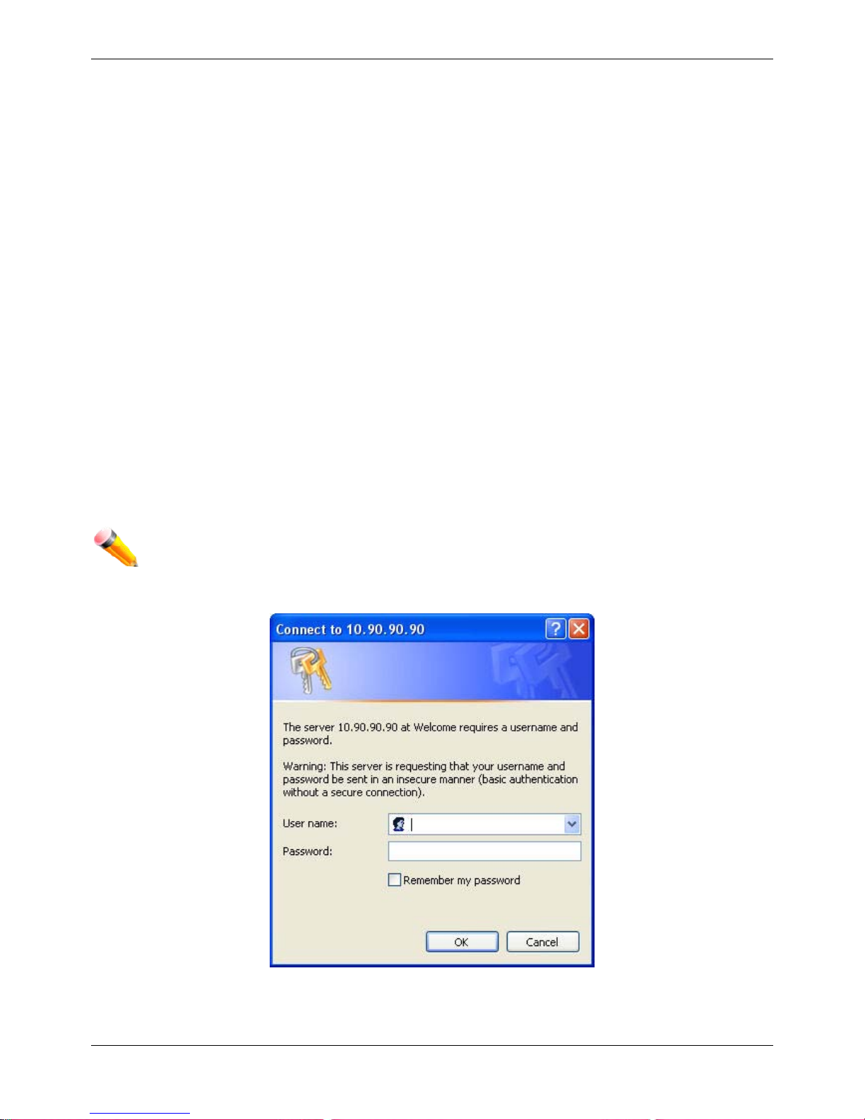
This opens the management module's user authentication window, as seen below.
Figure 1-1 Enter Network Password window
Leave both the User Name field and the Password field blank and click OK. This will open the Web-based user
interface. The Switch management features available in the web-based manager are explained below.
xStack® DGS-3620 Series Managed Switch Web UI Reference Guide
6
Web-based User Interface
The user interface provides access to various Switch configuration and management windows, allows you to view
performance statistics, and permits you to graphically monitor the system status.
Areas of the User Interface
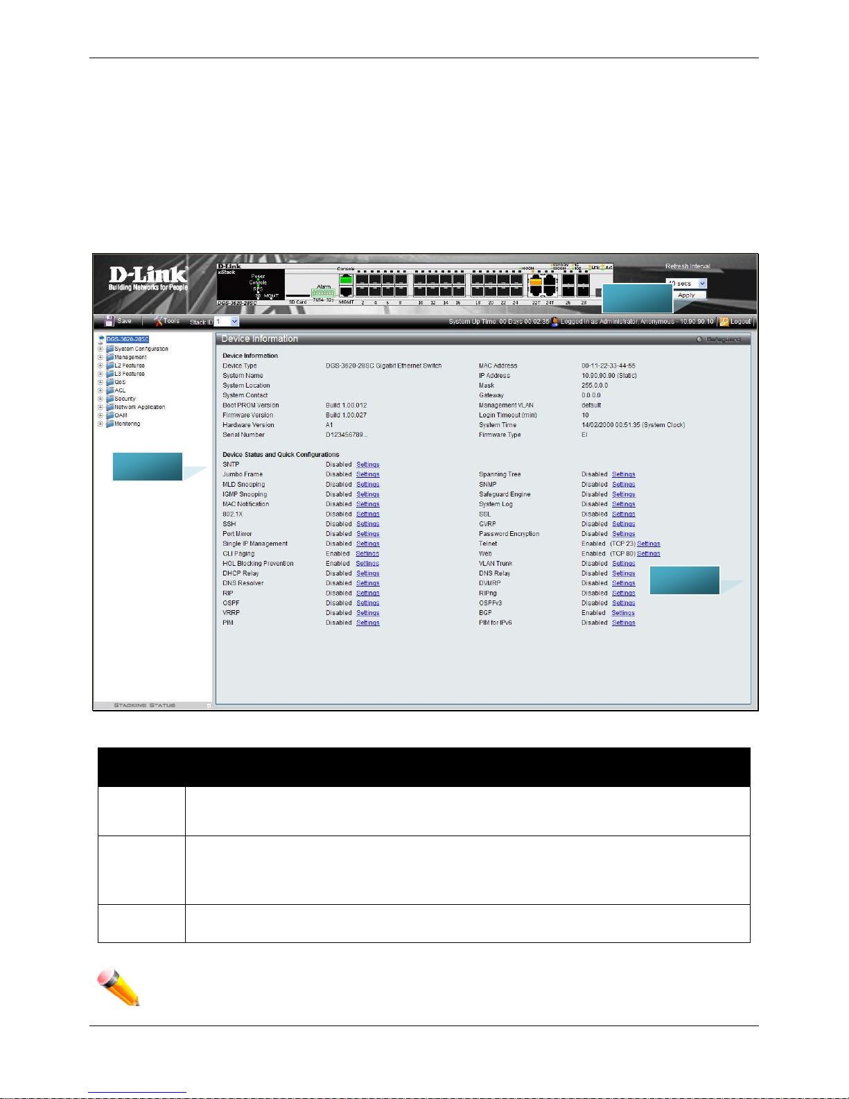
The figure below shows the user interface. Three distinct areas divide the user interface, as described in the table.
Figure 1-2 Main Web-Manager page
Area
Number
Function
Area 1
Select the menu or window to display. Open folders and click the hyperlinked menu buttons
and subfolders contained within them to display menus. Click the D-Link logo to go to the D-
Link website.
Area 2
Presents a graphical near real-time image of the front panel of the Switch. This area displays
the Switch's ports, console and management port, showing port activity.
Some management functions, including save, reboot, download and upload are accessible
here.
Area 3
Presents switch information based on user selection and the entry of configuration data.
NOTE: Any changes made to the Switch configuration during the current session must be saved in the
Save Configuration / Log window or use the command line interface (CLI) command save.
ARE A 2
ARE A 1
ARE A 3

xStack® DGS-3620 Series Managed Switch Web UI Reference Guide
7
Web Pages
When connecting to the management mode of the Switch with a web browser, a login screen is displayed. Enter a
user name and password to access the Switch's management mode.
Below is a list of the main folders available in the Web interface:
System Configuration - In this section the user will be able to configure features regarding the Switch’s
configuration.
Management - In this section the user will be able to configure features regarding the Switch’s management.
L2 Features - In this section the user will be able to configure features regarding the Layer 2 functionality of the
Switch.
L3 Features - In this section the user will be able to configure features regarding the Layer 3 functionality of the
Switch.
QoS - In this section the user will be able to configure features regarding the Quality of Service functionality of the
Switch.
ACL - In this section the user will be able to configure features regarding the Access Control List functionality of the
Switch.
Security - In this section the user will be able to configure features regarding the Switch’s security.
Network Application - In this section the user will be able to configure features regarding network applications
handled by the Switch.
OAM - In this section the user will be able to configure features regarding the Switch’s operations, administration
and maintenance (OAM).
Monitoring - In this section the user will be able to monitor the Switch’s configuration and statistics.
NOTE: Be sure to configure the user name and password in the User Accounts menu before
connecting the Switch to the greater network.

xStack® DGS-3620 Series Managed Switch Web UI Reference Guide
8
Chapter 2 System Configuration
Device Information
System Information Settings
Port Configuration
PoE
Serial Port Settings
Warning Temperature Settings
System Log configuration
Time Range Settings
Port Group Settings
Time Settings
User Accounts Settings
Command Logging Settings
Stacking
Device Information
This window contains the main settings for all the major functions for the Switch. It appears automatically when you
log on to the Switch. To return to the Device Information window after viewing other windows, click the DGS-3620
Series link.
The Device Information window shows the Switch’s MAC Address (assigned by the factory and unchangeable), the
Boot PROM Version, Firmware Version, Hardware Version, and many other important types of information. This is
helpful to keep track of PROM and firmware updates and to obtain the Switch’s MAC address for entry into another
network device’s address table, if necessary. In addition, this window displays the status of functions on the Switch
to quickly assess their current global status.
Many functions are hyper-linked for easy access to enable quick configuration from this window.
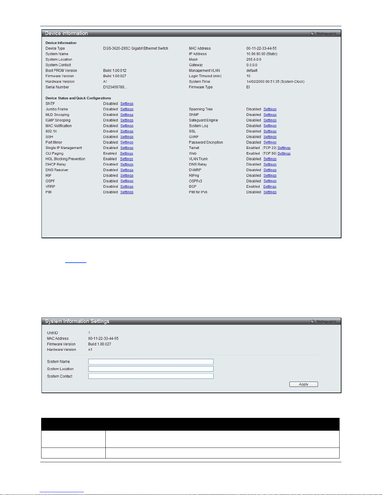
xStack® DGS-3620 Series Managed Switch Web UI Reference Guide
9
Figure 2-1 Device Information windo w
Click the
Settings
link to navigate to the appropriate feature page for configuration.
System Information Settings
The user can enter a System Name, System Location, and System Contact to aid in defining the Switch.
To view the following window, click System Configuration > System Information Settings, as show below:
Figure 2-2 System Information Settings window
The fields that can be configured are described below:
Parameter Description
System Name
Enter a system name for the Switch, if so desired. This name will identify it in the
Switch network.
System Location
Enter the location of the Switch, if so desired.
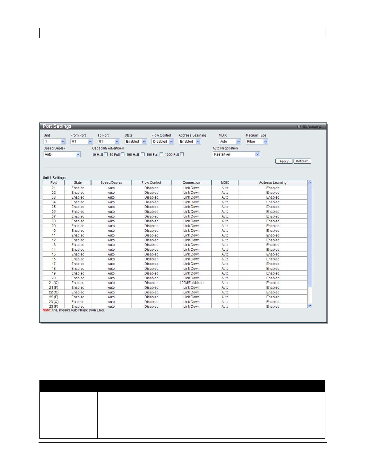
xStack® DGS-3620 Series Managed Switch Web UI Reference Guide
10
System Contact
Enter a contact name for the Switch, if so desired.
Click the Apply button to implement changes made.
Port Configuration
Port Settings
This page used to configure the details of the switch ports.
To view the following window, click System Configuration > Port Configuration > Port Settings, as show below:
Figure 2-3 Port Settings window
To configure switch ports:
1. Choose the port or sequential range of ports using the From Port and To Port drop-down menus.
2. Use the remaining drop-down menus to configure the parameters described below:
The fields that can be configured are described below:
Parameter Description
Unit
Select the unit you wish to configure.
From Port / To Port
Select the appropriate port range used for the configuration here.
State
Toggle the State field to either enable or disable a given port or group of ports.
Speed/Duplex Use the drop-down menu to select the speed in Auto, 10M Half, 10M Full, 100M Half,
100M Full, 1000M Full_Master and 1000M Full_Slave. Auto denotes auto-negotiation

xStack® DGS-3620 Series Managed Switch Web UI Reference Guide
11
among 10, 100 and 1000 Mbps devices, in full- or half-duplex (except 1000 Mbps which
is always full duplex). The Auto setting allows the port to automatically determine the
fastest settings the device the port is connected to can handle, and then to use those
settings. The other options are 10M Half, 10M Full, 100M Half, 100M Full, 1000M
Full_Master, 1000M Full_Slave, and 1000M Full. There is no automatic adjustment of
port settings with any option other than Auto.
The Switch allows the user to configure two types of gigabit connections; 1000M
Full_Master, and 1000M Full_Slave which refer to connections running a 1000BASE-T
cable for connection between the Switch port and other device capable of a gigabit
connection. The master setting (1000M Full_Master) will allow the port to advertise
capabilities related to duplex, speed and physical layer type. The master setting will also
determine the master and slave relationship between the two connected physical layers.
This relationship is necessary for establishing the timing control between the two
physical layers. The timing control is set on a master physical layer by a local source.
The slave setting (1000M Full_Slave) uses loop timing, where the timing comes from a
data stream received from the master. If one connection is set for 1000M Full_Master,
the other side of the connection must be set for 1000M Full_Slave. Any other
configuration will result in a link down status for both ports.
Capability
Advertised
When the Speed/Duplex is set to Auto, these capabilities are advertised during auto
negotiation.
Flow Control
Displays the flow control scheme used for the various port configurations. Ports
configured for full-duplex use 802.3x flow control, half-duplex ports use backpressure
flow control, and Auto ports use an automatic selection of the two. The default is
Disabled.
Connection
Here the current connection speed will be displayed.
MDIX Auto - Select auto for auto sensing of the optimal type of cabling.
Normal - Select normal for normal cabling. If set to normal state, the port is in MDI mode
and can be connected to a PC NIC using a straight-through cable or a port (in MDI
mode) on another switch through a cross-over cable.
Cross - Select cross for cross cabling. If set to cross state, the port is in MDIX mode, and
can be connected to a port (in MDI mode) on another switch through a straight cable.
Address Learning Enable or disable MAC address learning for the selected ports. When Enabled,
destination and source MAC addresses are automatically listed in the forwarding table.
When address learning is Disabled, MAC addresses must be manually entered into the
forwarding table. This is sometimes done for reasons of security or efficiency. See the
section on Forwarding/Filtering for information on entering MAC addresses into the
forwarding table. The default setting is Enabled.
Medium Type
If configuring the Combo ports, this defines the type of transport medium to be used.
Auto Negotiation
Use the drop-down menu to specify the auto-negotiation configuration.
Restart An – Select to restart the auto-negotiation process
Remote Fault Advertisedt - The remote fault advertisement option will be configured.
Click the Apply button to implement changes made.
Click the Refresh button to refresh the display section of this page.
Port Description Settings
The Switch supports a port description feature where the user may name various ports.
To view the following window, click System Configuration > Port Configuration > Port Description Settings, as
show below:
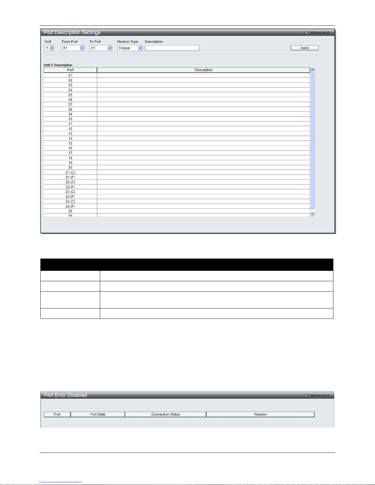
xStack® DGS-3620 Series Managed Switch Web UI Reference Guide
12
Figure 2-4 Port Description Settings window
The fields that can be configured are described below:
Parameter Description
Unit
Select the unit you wish to configure.
From Port / To Port
Select the appropriate port range used for the configuration here.
Medium Type
Specify the medium type for the selected ports. If configuring the Combo ports, the
Medium Type defines the type of transport medium to be used, whether Copper or Fiber.
Description
Users may then enter a description for the chosen port(s).
Click the Apply button to implement changes made.
Port Error Disabled
The following window displays the information about ports that have been disconnected by the Switch when a
packet storm occurs or a loop was detected.
To view the following window, click System Configuration > Port Configuration > Port Error Disabled, as show
below:
Figure 2-5 Port Error Disabled
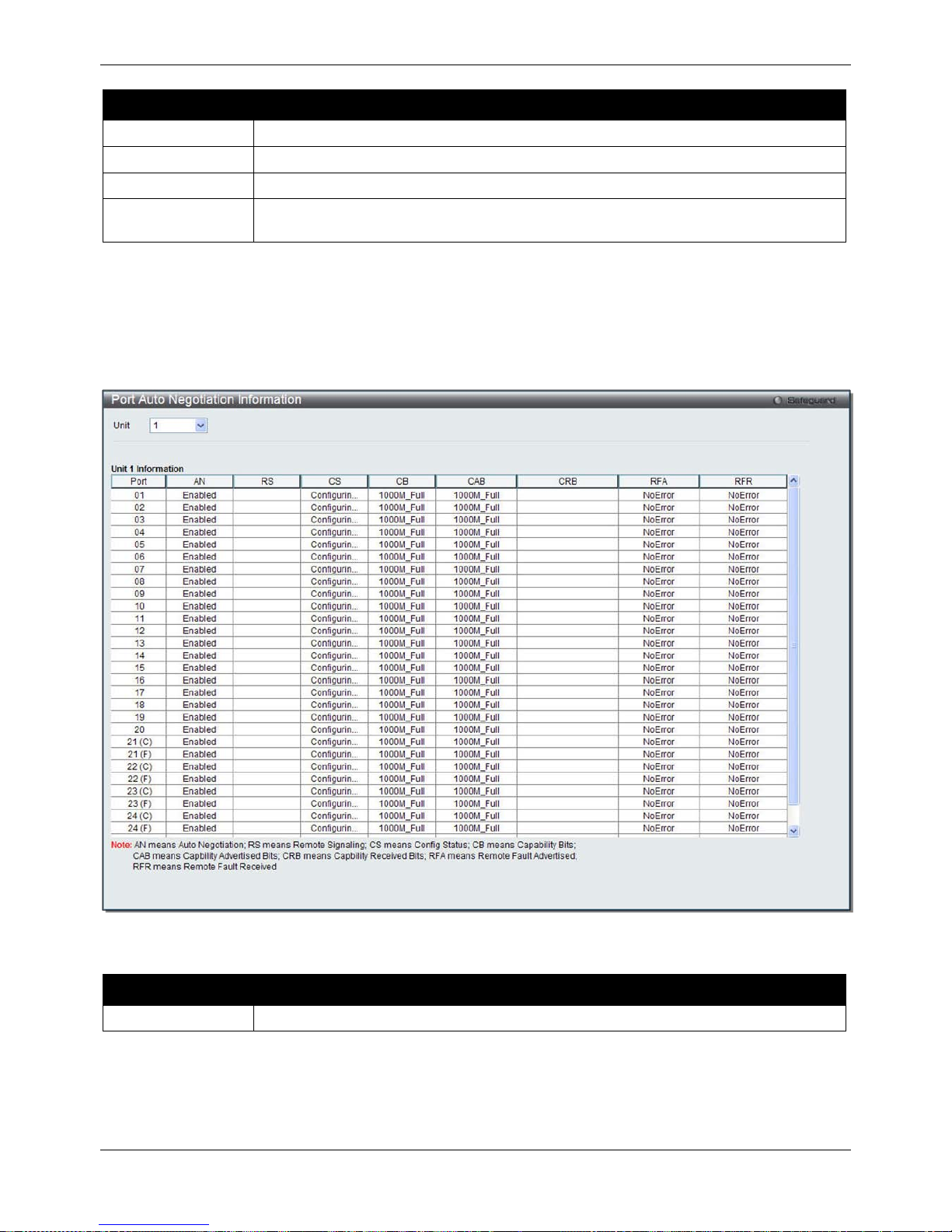
xStack® DGS-3620 Series Managed Switch Web UI Reference Guide
13
The fields that can be displayed are described below:
Parameter Description
Port
Display the port that has been error disabled.
Port State
Describe the current running state of the port, whether enabled or disabled.
Connection Status
Display the uplink status of the individual ports, whether enabled or disabled.
Reason
Describe the reason why the port has been error-disabled, such as it has become a
shutdown port for storm control.
Port Auto Negotiation Information
The following window displays the detailed auto negotiation information.
To view the following window, click System Configuration > Port Configuration > Port Auto Negotiation
Information, as show below:
Figure 2-6 Port Auto Negotiation Information window
The fields that can be configured are described below:
Parameter Description
Unit
Select the unit you wish to display.
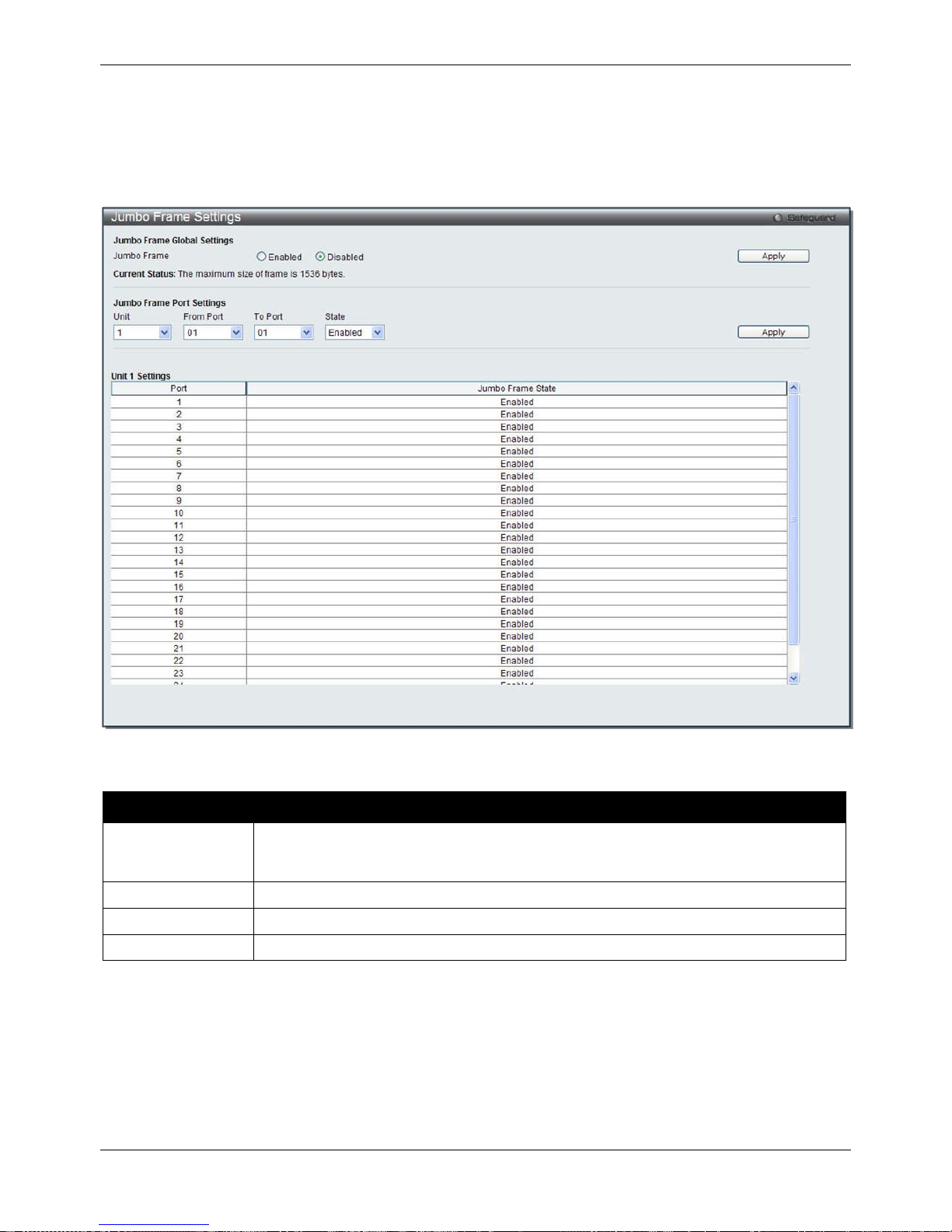
xStack® DGS-3620 Series Managed Switch Web UI Reference Guide
14
Jumbo Frame Settings
The Switch supports jumbo frames. Jumbo frames are Ethernet frames with more than 1,518 bytes of payload. The
Switch supports jumbo frames with a maximum frame size of up to 13312 bytes.
To view the following window, click System Configuration > Port Configuration > Jumbo Frame Settin g s, as
show below:
Figure 2-7 Jumbo Frame Settings window
The fields that can be configured are described below:
Parameter Description
Jumbo Frame
Use the radio buttons to enable or disable the Jumbo Frame function on the Switch. The
default is Disabled. When disabled, the maximum frame size is 1536 bytes. When
enabled, the maximum frame size is 13312 bytes.
Unit
Select the unit you wish to configure.
From Port / To Port
Select the appropriate port range used for the configuration here.
State
Use the drop-down menu to enable the Jumbo Frame for the port.
Click the Apply button to implement changes made.
PoE
The DGS-3620-28PC and DGS-3620-52P switches support Power over Ethernet (PoE) as defined by the IEEE
802.3af and 802.3at. All ports can support PoE up to 30W. Ports 1-24 can supply about 48 VDC power to Powered
Devices (PDs) over Category 5 or Category 3 UTP Ethernet cables. The Switch follows the standard PSE (Power
Sourcing Equipment) pinout Alternative A, whereby power is sent out over pins 1, 2, 3 and 6. The Switches work
with all D-Link 802.3af capable devices.
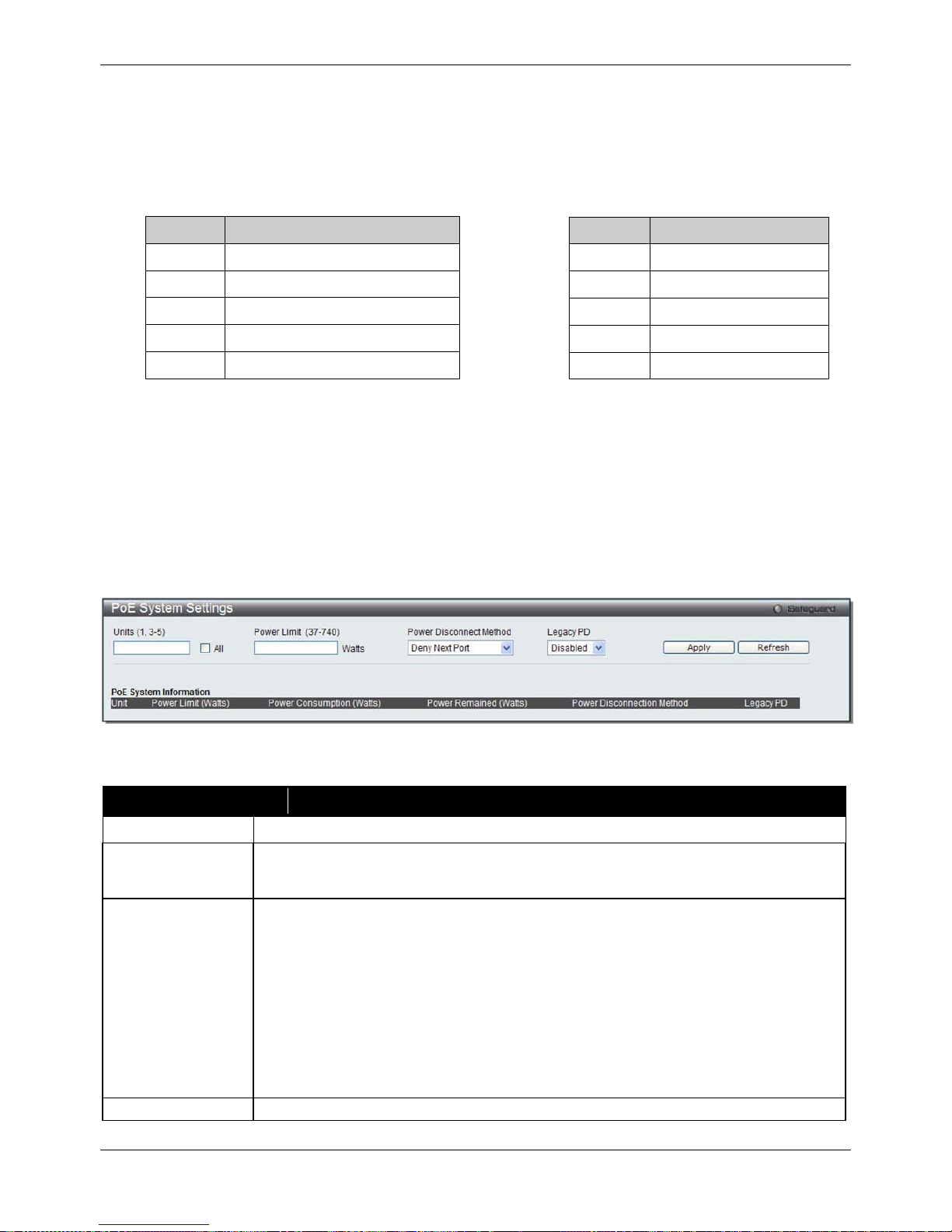
xStack® DGS-3620 Series Managed Switch Web UI Reference Guide
15
The Switch includes the following PoE features:
• Auto-discovery recognizes the connection of a PD (Powered Device) and automatically sends power to it.
• The Auto-disable feature occurs under two conditions: firstly, if the total power consumption exceeds the
system power limit; and secondly, if the per port power consumption exceeds the per port power limit.
• Active circuit protection automatically disables the port if there is a short. Other ports will remain active.
Based on 802.3af/at PDs receive power according to the following classification:
Class Maximum power available to PD
0 12.95W
1 3.84W
2 6.49W
3 12.95W
4 29.5W
To configure the PoE features on the Switch, click System Configuration > PoE. The PoE System Settings
window is used to assign a power limit and power disconnect method for the whole PoE system. To configure the
Power Limit for the PoE system, enter a value between 1W and 370W for the Switch in the Power Limit field.
When the total consumed power exceeds the power limit, the PoE controller (located in the PSE) disconnects the
power to prevent overloading the power supply.
PoE System Settings
To view the following window, click System Configuration > PoE > PoE System Settings, as show below:
Figure 2-8 PoE System Settings window
The following parameters can be configured:
Parameter Description
Unit
Select the unit you wish to configure. Tick the All check box to select all units.
Power Limit (37-
740)
Sets the limit of power to be used from the Switch’s power source to PoE ports. The user
may configure a Power Limit between 1 and 740W for the DGS-3620-28PC and DGS-
3620-52P. The default setting is 740W.
Power Disconnect
Method
The PoE controller uses either Deny Next Port or Deny Low Priority Port to offset the
power limit being exceeded and keeps the Switch’s power at a usable level. Use the drop
down menu to select a Power Disconnect Method. The default Power Disconnect
Method is Deny Next Port. Both Power Disconnection Methods are described below:
Deny Next Port – After the power limit has been exceeded, the next port attempting to
power up is denied, regardless of its priority. If Power Disconnection Method is set to
Deny Next Port, the system cannot utilize out of its maximum power capacity. The
maximum unused watt is 19W.
Deny Low Priority Port – After the power limit has been exceeded, the next port
attempting to power up causes the port with the lowest priority to shut down so as to
allow the high-priority and critical priority ports to power up.
Legacy PD
Use the drop-down menu to enable or disable detecting legacy PDs signal.
Click Apply to implement changes made.
PSE provides power according to the following classification:
Class Max power used by PSE
0 16.2W
1 4.2W
2 7.4W
3 16.2W
User define 31.2W
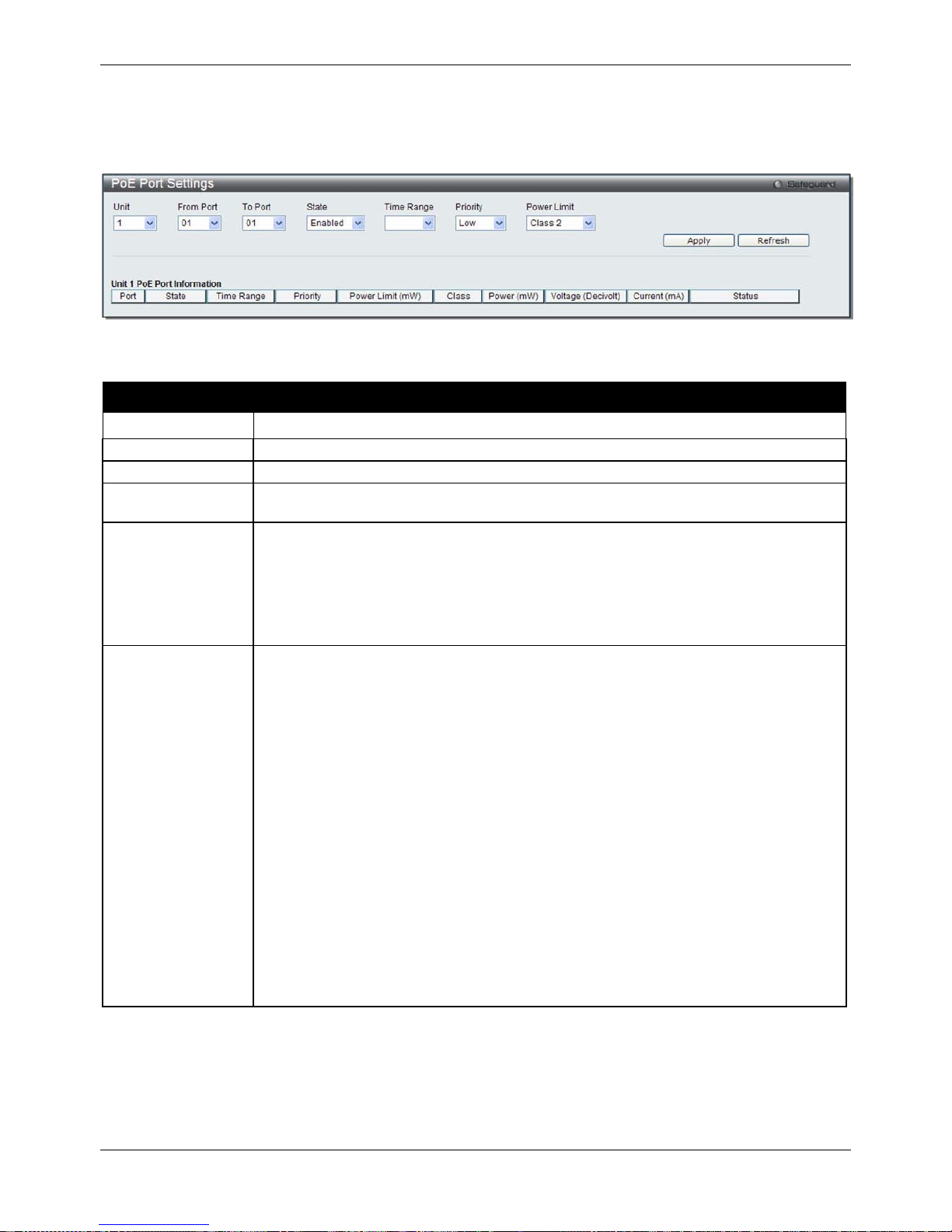
xStack® DGS-3620 Series Managed Switch Web UI Reference Guide
16
PoE Port Settings
To view the following window, click System Configuration > PoE > PoE Port Settings, as show below:
Figure 2-9 PoE Port Settings window
The following parameters can be configured:
Parameter Description
Unit
Select the unit you wish to configure.
From Port / To Port
Select a range of ports from the drop-down menus to be enabled or disabled for PoE.
State
Use the drop-down menu to enable or disable ports for PoE.
Time Range
Select a range of the time to the port set as POE. If Time Range is configured, the power
can only be supplied during the specified period of time.
Priority
Use the drop-down menu to select the priority of the PoE ports. Port priority determines
the priority which the system attempts to supply the power to the ports. There are three
levels of priority that can be selected, Critical, High, and Low. When multiple ports
happen to have the same level of priority, the port ID will be used to determine the
priority. The lower port ID has higher priority. The setting of priority will affect the order of
supplying power. Whether the disconnect method is set to deny low priority port, the
priority of each port will be used by the system to manage the supply of power to ports.
Power Limit
This function is used to configure the per-port power limit. If a port exceeds its power
limit, it will shut down.
Based on 802.3af/802.3at, there are different PD classes and power consumption
ranges;
Class 0 – 0.44~12.95W
Class 1 – 0.44~3.84W
Class 2 – 3.84~6.49W
Class 3 – 6.49~12.95W
Class 4 – 29.5W
The following is the power limit applied to the port for these five classes. For each class,
the power limit is a little more than the power consumption range for that class. This
takes into account any power loss on the cable. Thus, the following are the typical
values;
Class 0 – 16200mW
Class 1 – 4200mW
Class 2 – 7400mW
Class 3 – 16200mW
User Define – 35000mW
Click Apply to implement changes made. The port status of all PoE configured ports is displayed in the table in the
bottom half of the screen shown above.
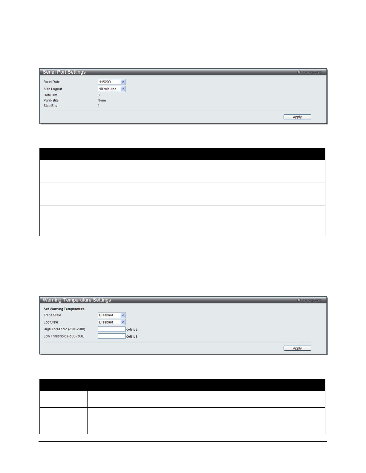
xStack® DGS-3620 Series Managed Switch Web UI Reference Guide
17
Serial Port Settings
This window allows the user to adjust the Baud Rate and the Auto Logout values.
To view the following window, click System Configuration > Serial Port Settings, as show below:
Figure 2-10 Serial Port Settings window
The fields that can be configured are described below:
Parameter Description
Baud Rate
Specify the baud rate for the serial port on the Switch. There are four possible baud rates to
choose from, 9600, 19200, 38400 and 115200. For a connection to the Switch using the
console port, the baud rate must be set to 115200, which is the default setting.
Auto Logout
Select the logout time used for the console interface. This automatically logs the user out
after an idle period of time, as defined. Choose from the following options: 2, 5, 10, 15
minutes or Never. The default setting is 10 minutes.
Data Bits
Display the data bits used for the serial port connection.
Parity Bits
Display the parity bits used for the serial port connection.
Stop Bits
Display the stop bits used for the serial port connection.
Click the Apply button to implement changes made.
Warning Temperature Settings
This window allows the user to configure the system warning temperature parameters.
To view the following window, click System Configuration > Warning Temperature Settings, as show below:
Figure 2-11 Warning Temperature Settings window
The fields that can be configured are described below:
Parameter Description
Traps State
Use the drop-down menu to enable or disable the traps state option of the warning
temperature setting.
Log State
Use the drop-down menu to enable or disable the log state option of the warning
temperature setting.
High Threshold
Enter the high threshold value of the warning temperature setting.
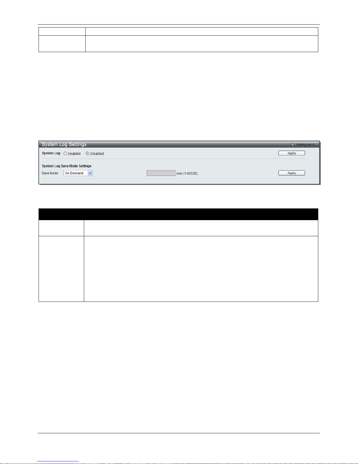
xStack® DGS-3620 Series Managed Switch Web UI Reference Guide
18
(-500-500)
Low Threshold
(-500-500)
Enter the low threshold value of the warning temperature setting.
Click the Apply button to implement changes made.
System Log configuration
System Log Settings
The Switch allows users to choose a method for which to save the switch log to the flash memory of the Switch.
To view the following window, click System Configuration > System Log Configuration > System Log Settings,
as show below:
Figure 2-12 System Log Settings window
The fields that can be configured are described below:
Parameter Description
System Log Use the radio buttons to enable or disable the system log settings. Click the Apply button to
accept the changes made.
Save Mode
Use the drop-down menu to choose the method for saving the switch log to the flash memory.
The user has three options:
On Demand – Users who choose this method will only save log files when they manually tell
the Switch to do so, either using the Save Log link in the Save folder.
Time Interval – Users who choose this method can configure a time interval by which the
Switch will save the log files, in the box adjacent to this configuration field. The user may set
a time between 1 and 65535 minutes.
Log Trigger – Users who choose this method will have log files saved to the Switch every
time a log event occurs on the Switch.
Click the Apply button to implement changes made.
System Log Server Settings
The Switch can send System log messages to up to four designated servers using the System Log Server.
To view the following window, click System Configuration > System Log Configuration > System Log Server
Settings, as show below:
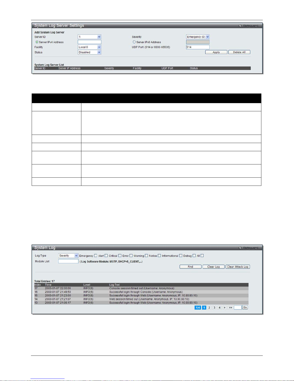
xStack® DGS-3620 Series Managed Switch Web UI Reference Guide
19
Figure 2-13 System Log Server Settings
The fields that can be configured are described below:
Parameter Description
Server ID
Syslog server settings index (1 to 4).
Severity
Use the drop-down menu to select the higher level of messages that will be sent. All
messages which level is higher than selecting level will be sent. The options are
Emergency(0), Alert(1), Critical(2), Error(3), Warning(4), Notice(5), Informational(6) and
Debug(7).
Server IPv4 Address
The IPv4 address of the Syslog server.
Server IPv6 Address
The IPv6 address of the Syslog server.
Facility Use the drop-down menu to select Local 0, Local 1, Local 2, Local 3, Local 4, Local 5,
Local 6, or Local 7.
UDP Port
(514 or 6000-65535)
Type the UDP port number used for sending Syslog messages. The default is 514.
Status
Choose Enabled or Disabled to activate or deactivate.
Click the Apply button to accept the changes made.
Click the Delet e All button to remove all servers configured.
System Log
Users can view and delete the local history log as compiled by the Switch's management agent.
To view the following window, click System Configuration > System Log Configuration > System Log, as show
below:
Figure 2-14 System Log window
The Switch can record event information in its own log. Click Go to go to the next page of the System Log window.
The fields that can be configured or displayed are described below:
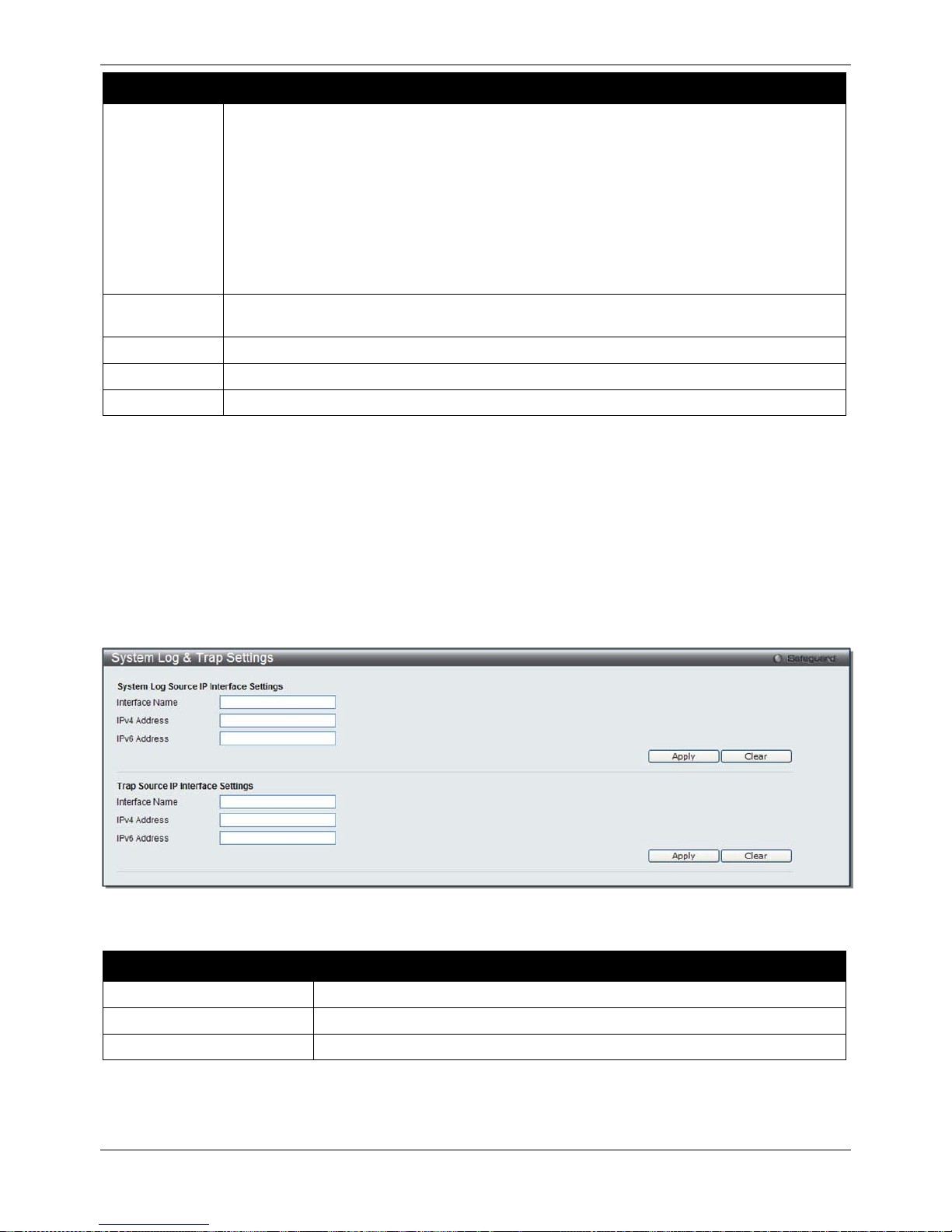
xStack® DGS-3620 Series Managed Switch Web UI Reference Guide
20
Parameter Description
Log Type
In the drop-down menu the user can select the log type that will be displayed.
Severity - When selecting Severity from the drop-down menu, a secondary tick must be
made. Secondary ticks are Emergency, Alert, Critical, Error, Warning, Notice,
Informational and Debug. To view all information in the log, simply tick the All check box.
Enter the module name to search for the specific module.
Module List - When selecting Module List, the module name must be manually entered.
Available modules are CFM_EXT, DHCPv6_CLIENT, DHCPv6_RELAY, DHCPv6_SERVER,
ERPS, ERROR_LOG MSTP, OSPFV2 and VRRP.
Attack Log - When selecting Attack Log all attacks will be listed. Select a unit from the drop-
down menu to display the result of the unit.
Index
A counter incremented whenever an entry to the Switch's history log is made. The table
displays the last entry (highest sequence number) first.
Time
Display the time in days, hours, minutes, and seconds since the Switch was last restarted.
Level
Display the level of the log entry.
Log Text
Display text describing the event that triggered the history log entry.
Click the Find button to display the log in the display section according to the selection made.
Click the Clear Log button to clear the entries from the log in the display section.
Click the Clear Attack Log button to clear the entries from the attack log in the display section.
Enter a page number and click the Go button to navigate to a specific page when multiple pages exist.
System Log & Trap Settings
The Switch allows users to configure the system log source IP interface addresses here.
To view the following window, click System Configuration > System Log Configuration > System Log & Trap
Settings, as show below:
Figure 2-15 System Log & Trap Settings window
The fields that can be configured are described below:
Parameter Description
Interface Name
Enter the IP interface name used.
IPv4 Address
Enter the IPv4 address used.
IPv6 Address
Enter the IPv6 address used.
Click the Apply button to accept the changes made.
Click the Clear button to clear all the information entered in the fields.
 Loading...