

Page 1
xStack DGS-3400 Series Layer 2 Gigabit Ethernet Managed Switch
2
5
User Manual
Product Model:
Layer 2 Gigabit EthernetManaged Switch
Release
.3
TM
DGS-3400 Series
i
Page 2

xStack DGS-3400 Series Layer 2 Gigabit Ethernet Managed Switch
_____________________________________________
Information in this document is subject to change without notice.
© 2008 D-Link Computer Corporation. All rights reserved.
Reproduction in any manner whatsoever without the written permission of D-Link Computer Corporation is strictly forbidden.
Trademarks used in this text: D-Link and the D-LINK logo are trademarks of D-Link Computer Corporation; Microsoft and Windows are registered trademarks of
Microsoft Corporation.
Other trademarks and trade names may be used in this document to refer to either the entities claiming the marks and names or their products. D-Link Computer
Corporation disclaims any proprietary interest in trademarks and trade names other than its own.
August 2008 P/N 651GS3400065G
ii
Page 3

Table of Contents
Intended Readers............................................................................................................................................................................ x
Typographical Conventions............................................................................................................................................................................x
Notes, Notices, and Cautions ........................................................................................................................................................ xi
Safety Instructions........................................................................................................................................................................ xii
Safety Cautions............................................................................................................................................................................................ xii
General Precautions for Rack-Mountable Products .................................................................................................................................... xiii
Lithium Battery Precaution.....................................................................................................................................................................xiv
Protecting Against Electrostatic Discharge..................................................................................................................................................xiv
Introduction......................................................................................................................................................1
Switch Description.....................................................................................................................................................................................1
Features...........................................................................................................................................................................................................2
Ports................................................................................................................................................................................................................3
Front-Panel Components ........................................................................................................................................................................... 4
LED Indicators................................................................................................................................................................................................5
Rear Panel Description..............................................................................................................................................................................7
Side Panel Description...............................................................................................................................................................................8
Installation........................................................................................................................................................9
Package Contents.......................................................................................................................................................................................9
Installation Guidelines...............................................................................................................................................................................9
Installing the Switch without the Rack....................................................................................................................................................10
Installing the Switch in a Rack................................................................................................................................................................10
Mounting the Switch in a Standard 19" Rack.......................................................................................................................................... 11
Power On ......................................................................................................................................................................................................11
Power Failure...........................................................................................................................................................................................11
Installing the SFP ports............................................................................................................................................................................12
The Optional Module....................................................................................................................................................................................13
Installing the Module...............................................................................................................................................................................14
External Redundant Power System...............................................................................................................................................................15
Connecting the Switch...................................................................................................................................17
Switch to End Node.................................................................................................................................................................................17
Switch to Switch......................................................................................................................................................................................17
Connecting To Network Backbone or Server ...............................................................................................................................................18
Introduction to Switch Management ...........................................................................................................19
Management Options............................................................................................................................... ................................................19
Connecting the Console Port (RS-232 DCE)...........................................................................................................................................20
Managing the Switch for the First Time..................................................................................................................................................21
Password Protection.................................................................................................................................................................................22
IP Address Assignment............................................................................................................................................................................24
Web-based Switch Configuration.................................................................................................................26
Introduction.................................................................................................................................................................................. 26
Logging in to the Web Manager ...................................................................................................................................................................26
Page 4

Web-based User Interface.............................................................................................................................................................................27
Areas of the User Interface......................................................................................................................................................................27
Web Pages.....................................................................................................................................................................................................28
Configuring the Switch..................................................................................................................................30
Device Information ...................................................................................................................................................................... 31
IPv6.............................................................................................................................................................................................. 33
Overview.......................................................................................................................................................................................................33
Packet Format...............................................................................................................................................................................................34
IPv6 Header.............................................................................................................................................................................................34
Extension Headers...................................................................................................................................................................................35
Packet Fragmentation ..............................................................................................................................................................................35
Address Format.............................................................................................................................................................................................35
Types .......................................................................................................................................................................................................36
ICMPv6.........................................................................................................................................................................................................37
Neighbor Discovery......................................................................................................................................................................................37
Neighbor Unreachability Detection .........................................................................................................................................................37
Duplicate Address Detection (DAD).......................................................................................................................................................38
Assigning IP Addresses...........................................................................................................................................................................38
IP Interface Setup ....................................................................................................................................................................................38
IP Address.................................................................................................................................................................................... 39
Setting the Switch's IP Address using the Console Interface...................................................................................................................40
Interface Settings.......................................................................................................................................................................... 41
IPv4 Interface Settings.............................................................................................................................................................................41
IPv6 Interface Settings.............................................................................................................................................................................42
Stacking........................................................................................................................................................................................ 46
Stack Switch Swapping ...........................................................................................................................................................................47
Stacking Mode Settings...........................................................................................................................................................................48
Box Information.......................................................................................................................................................................................48
Port Configuration........................................................................................................................................................................ 49
Port Error Disabled..................................................................................................................................................................................50
Port Description.......................................................................................................................................................................................51
Cable Diagnostics....................................................................................................................................................................................51
User Accounts.............................................................................................................................................................................. 53
Port Mirroring.............................................................................................................................................................................. 54
Mirroing within the Switch Stack............................................................................................................................................................55
System Log .................................................................................................................................................................................. 56
System Log Save Mode Settings .............................................................................................................................................................57
System Severity Settings.............................................................................................................................................................. 59
SNTP Settings.............................................................................................................................................................................. 60
Time Settings...........................................................................................................................................................................................60
Time Zone and DST......................................................................................................................................................................................61
MAC Notification Settings .......................................................................................................................................................... 63
TFTP Services.............................................................................................................................................................................. 64
Multiple Image Services .............................................................................................................................................................. 66
Page 5

Firmware Information..............................................................................................................................................................................66
Config Firmware Image...........................................................................................................................................................................67
Ping Test ...................................................................................................................................................................................... 68
IPv4 Ping Test .........................................................................................................................................................................................68
IPv6 Ping Test .........................................................................................................................................................................................69
Safeguard Engine......................................................................................................................................................................... 70
Static ARP Settings...................................................................................................................................................................... 72
IPv6 Neighbor.............................................................................................................................................................................. 73
IPv6 Neighbor Settings ............................................................................................................................... .............................................73
Routing Table............................................................................................................................................................................... 75
IPv4 Static/Default Route Settings................................................................................................................................................................ 75
IPv6 Static/Default Route Settings................................................................................................................................................................ 76
DHCP/BOOTP Relay................................................................................................................................................................... 78
DHCP / BOOTP Relay Global Settings........................................................................................................................................................78
The Implementation of DHCP Information Option 82............................................................................................................................80
DHCP/BOOTP Relay Interface Settings.......................................................................................................................................................81
DHCP Auto Configuration Settings............................................................................................................................................. 82
SNMP Manager............................................................................................................................................................................ 83
SNMP Trap Settings................................................................................................................................................................................84
SNMP User Table....................................................................................................................................................................................84
SNMP View Table...................................................................................................................................................................................86
SNMP Group Table............................................................................................................................... ..................................................87
SNMP Community Table ........................................................................................................................................................................89
SNMP Host Table ....................................................................................................................................................................................90
SNMP Engine ID.....................................................................................................................................................................................91
IP-MAC-Port Binding.................................................................................................................................................................. 92
ACL Mode....................................................................................................................................................................................................92
IP-MAC Binding Port...................................................................................................................................................................................94
IP-MAC Binding Table.................................................................................................................................................................................95
IP-MAC Binding Blocked.............................................................................................................................................................................96
PoE Configuration........................................................................................................................................................................ 97
PoE System Settings .....................................................................................................................................................................................97
PoE Port Settings ..........................................................................................................................................................................................99
Single IP Management (SIM) Overview.................................................................................................................................... 101
The Upgrade to v1.61 ............................................................................................................................................................................102
Single IP vs. Switch Stacking................................................................................................................................................................103
SIM Using the Web Interface................................................................................................................................................................103
Topology.....................................................................................................................................................................................................104
Tool Tips ...............................................................................................................................................................................................107
Menu Bar...............................................................................................................................................................................................111
Firmware Upgrade ......................................................................................................................................................................................112
Configuration Backup/Restore....................................................................................................................................................................112
Upload Log.................................................................................................................................................................................................113
Layer 2 Features ..........................................................................................................................................114
VLANs........................................................................................................................................................................................................114
Page 6

Understanding IEEE 802.1p Priority.....................................................................................................................................................114
VLAN Description......................................................................................................................................................................................114
Notes about VLANs on the DGS-3400 Series.......................................................................................................................................115
IEEE 802.1Q VLANs .................................................................................................................................................................................115
802.1Q VLAN Tags............................................................................................................................................................................... 116
Port VLAN ID .......................................................................................................................................................................................117
Tagging and Untagging .........................................................................................................................................................................117
Ingress Filtering.....................................................................................................................................................................................118
Default VLANs......................................................................................................................................................................................118
Port-based VLANs.................................................................................................................................................................................118
VLAN Segmentation ............................................................................................................................................................................. 119
VLAN and Trunk Groups......................................................................................................................................................................119
Protocol VLANs....................................................................................................................................................................................119
Static VLAN Entry .....................................................................................................................................................................................119
GVRP Settings............................................................................................................................................................................................123
Double VLANs...........................................................................................................................................................................................124
Regulations for Double VLANs ............................................................................................................................................................125
Double VLAN.............................................................................................................................................................................................126
PVID Auto Assign......................................................................................................................................................................................128
MAC-based VLAN Settings.......................................................................................................................................................................129
Trunking..................................................................................................................................................................................... 130
Understanding Port Trunk Groups.........................................................................................................................................................130
Link Aggregation........................................................................................................................................................................................131
LACP Port Settings..................................................................................................................................................................................... 134
IGMP Snooping ......................................................................................................................................................................... 137
IGMP Snooping Settings ............................................................................................................................................................................137
Router Port Settings....................................................................................................................................................................................138
ISM VLAN ................................................................................................................................................................................................. 140
Restrictions and Provisos.......................................................................................................................................................................140
Limited Multicast Address Range............................................................................................................................................................... 142
MLD Snooping .......................................................................................................................................................................... 144
MLD Control Messages.........................................................................................................................................................................144
MLD Snooping Settings.............................................................................................................................................................................. 144
MLD Router Port Settings ..........................................................................................................................................................................146
Loopback Detection Global Settings..........................................................................................................................................148
Spanning Tree............................................................................................................................................................................ 150
802.1s MSTP.........................................................................................................................................................................................150
802.1w Rapid Spanning Tree.................................................................................................................................................................150
Port Transition States............................................................................................................................................................................. 150
Edge Port...............................................................................................................................................................................................151
P2P Port.................................................................................................................................................................................................151
802.1D/802.1w/802.1s Compatibility ....................................................................................................................................................151
STP Bridge Global Settings ........................................................................................................................................................................152
MST Configuration Identification...............................................................................................................................................................155
MSTP Port Information ..............................................................................................................................................................................157
Page 7

STP Instance Settings..................................................................................................................................................................................159
STP Port Settings........................................................................................................................................................................................160
Forwarding & Filtering.............................................................................................................................................................. 162
Unicast Forwarding.....................................................................................................................................................................................162
Multicast Forwarding..................................................................................................................................................................................162
Multicast Filtering Mode.............................................................................................................................................................................163
QoS................................................................................................................................................................165
QoS.............................................................................................................................................................................................................165
The Advantages of QoS..............................................................................................................................................................................165
Understanding QoS................................................................................................................................................................................166
Bandwidth Control......................................................................................................................................................................................168
QoS Scheduling Mechanism.......................................................................................................................................................................169
QoS Output Scheduling ..............................................................................................................................................................................170
Configuring the Combination Queue.....................................................................................................................................................171
802.1P Default Priority...............................................................................................................................................................................172
802.1P User Priority....................................................................................................................................................................................173
ACL (Access Control List)..........................................................................................................................174
Time Range................................................................................................................................................................................ 174
Access Profile Table .................................................................................................................................................................. 176
CPU Interface Filtering.............................................................................................................................................................. 189
CPU Interface Filtering State Settings........................................................................................................................................................189
CPU Interface Filtering Table.....................................................................................................................................................................189
Security.........................................................................................................................................................202
Authorization Network State Settings........................................................................................................................................ 202
Traffic Control ........................................................................................................................................................................... 203
Port Security............................................................................................................................................................................... 205
Port Security Entries...................................................................................................................................................................................206
802.1X........................................................................................................................................................................................ 207
Guest VLANs..............................................................................................................................................................................................212
Limitations Using the Guest VLAN ......................................................................................................................................................212
Configure 802.1X Authenticator.................................................................................................................................................................213
Configure 802.1x Guest VLAN............................................................................................................................... ...................................215
Authentic RADIUS Server..........................................................................................................................................................................216
Trust Host................................................................................................................................................................................... 217
Access Authentication Control................................................................................................................................................... 218
Authentication Policy & Parameters...........................................................................................................................................................219
Application's Authentication Settings.........................................................................................................................................................219
Authentication Server Group ...................................................................................................................................................................... 220
Authentication Server Host......................................................................................................................................................................... 221
Login Method Lists .....................................................................................................................................................................................223
Enable Method Lists...................................................................................................................................................................................224
Configure Local Enable Password..............................................................................................................................................................227
Enable Admin .............................................................................................................................................................................................227
MAC Based Access Control ...................................................................................................................................................... 228
Page 8

MAC Based Access Control Global Settings.............................................................................................................................................. 228
MAC Based Access Control Local MAC Settings......................................................................................................................................229
Traffic Segmentation.................................................................................................................................................................. 231
Secure Socket Layer (SSL)........................................................................................................................................................ 232
Download Certificate..................................................................................................................................................................................232
SSL Configuration ...................................................................................................................................................................................... 233
Secure Shell (SSH)..................................................................................................................................................................... 235
SSH Server Configuration...........................................................................................................................................................................235
SSH Authentication Mode ..........................................................................................................................................................................236
SSH User Authentication Mode............................................................................................................................... ...................................238
JWAC (Japanese Web-based Access Control)........................................................................................................................... 240
JWAC Global Configuration.......................................................................................................................................................................240
JWAC Port Settings....................................................................................................................................................................................242
JWAC User Account...................................................................................................................................................................................245
JWAC Host Information.............................................................................................................................................................................246
Monitoring....................................................................................................................................................247
Device Status.............................................................................................................................................................................. 248
Stacking Information.................................................................................................................................................................. 248
Module Information................................................................................................................................................................... 249
CPU Utilization.......................................................................................................................................................................... 250
Port Utilization........................................................................................................................................................................... 251
Packets ....................................................................................................................................................................................... 252
Received (Rx)........................................................................................................................................................................................252
UMB Cast (RX).....................................................................................................................................................................................254
Transmitted (TX)...................................................................................................................................................................................256
Errors.......................................................................................................................................................................................... 258
Received (RX).......................................................................................................................................................................................258
Transmitted (TX)...................................................................................................................................................................................260
Packet Size................................................................................................................................................................................. 262
Browse Router Port.................................................................................................................................................................... 265
Browse MLD Router Port.......................................................................................................................................................... 266
VLAN Status.............................................................................................................................................................................. 267
VLAN Status Port...................................................................................................................................................................... 268
Port Access Control....................................................................................................................................................................269
RADIUS Authentication.............................................................................................................................................................................269
RADIUS Account Client.............................................................................................................................................................................270
MAC Address Table .................................................................................................................................................................. 272
IGMP Snooping Group.............................................................................................................................................................. 273
MLD Snooping Group............................................................................................................................................................... 274
Switch Logs................................................................................................................................................................................ 275
Browse ARP Table..................................................................................................................................................................... 276
Session Table ............................................................................................................................................................................. 277
IP Forwarding Table.................................................................................................................................................................. 278
Browse Routing Table................................................................................................................................................................279
Page 9

MAC Based Access Control Authentication Status................................................................................................................... 280
Save, Reset and Reboot................................................................................................................................281
Reset........................................................................................................................................................................................... 281
Reboot System........................................................................................................................................................................... 282
Save Services ............................................................................................................................................................................. 283
Save Changes..............................................................................................................................................................................................283
Configuration Information............................................................................................................................... ...........................................284
Current Configuration Settings...................................................................................................................................................................285
Logout........................................................................................................................................................................................ 285
Appendix A...................................................................................................................................................286
Technical Specifications.............................................................................................................................................................................286
Appendix B...................................................................................................................................................288
Cables and Connectors................................................................................................................................................................................288
Appendix C...................................................................................................................................................289
Cable Lengths ............................................................................................................................................................................................. 289
Appendix D...................................................................................................................................................290
Switch Log Entries......................................................................................................................................................................................290
Glossary ........................................................................................................................................................302
Warranties/Registration..............................................................................................................................304
Technical Support........................................................................................................................................313
International Offices....................................................................................................................................340
Page 10

xStack DGS-3400 Series Layer 2 Gigabit Ethernet Managed Switch
Intended Readers
The xStack DGS-3400 series Ma nual contains information for setup and management of the Switch. This manual is intended for
network managers familiar with network management concepts and terminology.
Typographical Conventions
Convention Description
[ ]
Bold font
Boldface Typewriter
Font
Initial capital letter
Italics
Menu Name > Menu
Option
In a command line, square brackets indicate an optional entry. For example: [copy
filename] means that optionally you can type copy followed by the name of the file. Do
not type the brackets.
Indicates a button, a toolbar icon, menu, or menu item. For example: Open the File
menu and choose Cancel. Used for emphasis. May also indicate system messages or
prompts appearing on screen. For example: You have mail. Bold font is also used to
represent filenames, program names and commands. For example: use the copy
command.
Indicates commands and responses to prompts that must be typed exactly as printed in
the manual.
Indicates a window name. Names of keys on the keyboard have initial capitals. For
example: Click Enter.
Indicates a window name or a field. Also can indicate a variables or parameter that is
replaced with an appropriate word or string. For example: type filename means that the
actual filename should be typed instead of the word shown in italic.
Menu Name > Menu Option Indicates the menu structure. Device > Port > Port
Properties means the Port Properties menu option under the Port menu option that is
located under the Device menu.
x
Page 11

xStack DGS-3400 Series Layer 2 Gigabit Ethernet Managed Switch
Notes, Notices, and Cautions
A NOTE indicates important information that helps make better use of the
device.
A NOTICE indicates either potential damage to hardware or loss of data
and tells how to avoid the problem.
A CAUTION indicates a potential for property damage, personal injury, or
death.
xi
Page 12

xStack DGS-3400 Series Layer 2 Gigabit Ethernet Managed Switch
Safety Instructions
Use the following safety guidelines to ensure your own personal safety and to help protect your system from potential damage.
Throughout this safety section, the caution icon (
) is used to indicate cautions and precautions that need to be reviewed and
followed.
Safety Cautions
To reduce the risk of bodily injury, electrical shock, fire, and damage to the equipment, observe the following precautions.
• Observe and follow service markings.
• Do not service any product except as explained in the system documentation.
• Opening or removing covers that are marked with the triangular symbol with a lightning bolt may expose the user to
electrical shock.
• Only a trained service technician should service components inside these compartments.
• If any of the following conditions occur, unplug the product from the electrical outlet and replace the part or contact your
trained service provider:
• Damage to the power cable, extension cable, or plug.
• An object has fallen into the product.
• The product has been exposed to water.
• The product has been dropped or damaged.
• The product does not operate correctly when the operating instructions are correctly followed.
• Keep your system away from radiators and heat sources. Also, do not block cooling vents.
• Do not spill food or liquids on system components, and never operate the product in a wet environment. If the system gets
wet, see the appropriate section in the troubleshooting guide or contact your trained service provider.
• Do not push any objects into the openings of the system. Doing so can cause fire or electric shock by shorting out interior
components.
• Use the product only with approved equipment.
• Allow the product to cool before removing covers or touching internal components.
• Operate the product only from the type of external power source indicated on the electrical ratings label. If unsure of the type
of power source required, consult your service provider or local pow er compan y.
• To help avoid damaging the system, be sure the voltage selection switch (if provided) on the power supply is set to match the
power available at the Switch’s location:
• 115 volts (V)/60 hertz (Hz) in most of North and South America and some Far Eastern countries such as South Korea
and Taiwan
• 100 V/50 Hz in eastern Japan and 100 V/60 Hz in western Japa n
• 230 V/50 Hz in most of Europe, the Middle East, and the Far East
• Also, be sure that attached devices are electrically rated to operate with the power available in your location.
• Use only approved power cable(s). If you have not been provided with a power cable for your system or for any AC-
powered option intended for your system, purchase a power cable th at is approved for us e in your country. The power cable
must be rated for the product and for the voltage and current marked on the product's electrical ratings label. The voltage and
current rating of the cable should be greater than the ratings marked on the product.
• To help prevent electric shock, plug the system and peripheral power cables into properly grounded electrical outlets. These
cables are equipped with three-prong plugs to help ensure proper grounding. Do not use adapter plugs or remove the
grounding prong from a cable. If using an extension cable is necessary, use a 3-wire cable with properly grounded plugs.
xii
Page 13
xStack DGS-3400 Series Layer 2 Gigabit Ethernet Managed Switch
• Observe extension cable and power strip ratings. Make su re that the total ampere rating of all products plugged into the
extension cable or power strip does not exceed 80 percent of the ampere ratings limit for the extension cable or power strip.
• To help protect the system from sudden, transient increases and decreases in electrical power, use a surge suppressor, line
conditioner, or uninterruptible power supply (UPS).
• Position system cables and power cables carefully; route cables so that they cannot be stepped on or tripped over. Be sure
that nothing rests on any cables.
• Do not modify power cables or plugs. Consult a licensed electrician or your power company for site modifications. Always
follow your local/national wiring rules.
• When connecting or disconnecting power to hot-pluggable power supplies, if offered with your system, observe the
following guidelines:
• Install the power supply before connecting the power cable to the power supply.
• Unplug the power cable before removing the power supply.
• If the system has multiple sources of power, disconnect power from the system by unplugging all power cables from
the power supplies.
• Move products with care; ensure that all casters and/or stabilizers are firmly connected to the system. Avoid sudden stops
and uneven surfaces.
General Precautions for Rack-Mountable Products
Observe the following precautions for rack stability an d safety. Also, refer to the rack installation documentation accompanyin g
the system and the rack for specific caution statements and procedures.
• Systems are considered to be components in a rack. Thus, "component" refers to any system as well as to various peripherals
or supporting hardware.
• Before working on the rack, make sure that the stabilizers are secured to the rack, extended to the floor, and that the full
weight of the rack rests on the floor. Install front and side stabilizers on a single rack or front stabilizers for joined multiple
racks before working on the rack.
• Always load the rack from the bottom up, and load the heaviest item in the rack first.
• Make sure that the rack is level and stable before extending a component from the rack.
• Use caution when pressing the component rail release latches and sliding a component into or out of a rack; the slide rails
can pinch your fingers.
CAUTION: Installing systems in a rack without the front and side stabilizers installed could
cause the rack to tip over, potentially resulting in bodily injury under certain circumstances.
Therefore, always install the stabilizers before installing components in the rack. After
installing system/components in a rack, never pull more than one component out of the
rack on its slide assemblies at one time. The weight of more than one extended
component could cause the rack to tip over and may result in serious injury.
• After a component is inserted into the rack, carefully extend the rail into a locking position, and then slide the component
into the rack.
• Do not overload the AC supply branch circuit that provides power to the rack. The total rack load should not exceed 80
percent of the branch circuit rating.
• Ensure that proper airflow is provided to components in the rack.
• Do not step on or stand on any component when servicing other components in a rack.
xiii
Page 14
xStack DGS-3400 Series Layer 2 Gigabit Ethernet Managed Switch
NOTE: A qualified electrician must perform all connections to DC power and to safety
grounds. All electrical wiring must comply with applicable local or national codes and
practices.
CAUTION: Never defeat the ground conductor or operate the equipment in the absence
of a suitably installed ground conductor. Contact the appropriate electrical inspection
authority or an electrician if uncertain that suitable grounding is available.
CAUTION: The system chassis must be positively grounded to the rack cabinet frame.
Do not attempt to connect power to the system until grounding cables are connected.
Completed power and safety ground wiring must be inspected by a qualified electrical
inspector. An energy hazard will exist if the safety ground cable is omitted or
disconnected.
Lithium Battery Precaution
CAUTION: Incorrectly replacing the lithium battery of the Switch may cause the battery to
explode. Replace this battery only with the same or equivalent type recommended by the
manufacturer. Discard used batteries according to the manufacturers instructions.
Protecting Against Electrostatic Discharge
Static electricity can harm delicate components inside the system. To prevent static damage, discharge static electricity from your
body before touching any of the electronic components, such as the microprocessor. This can be done by periodically touching an
unpainted metal surface on the chassis.
The following steps can also be taken prevent damage from electrostatic discharge (ESD):
1. When unpacking a static-sensitive component from its shipping carton, do not remove the component from the antistatic
packing material until ready to install the component in the system. Just before unwrapping the antistatic packaging, be
sure to discharge static electricity from your body.
2. When transporting a sensitive component, first place it in an antistatic container or packaging.
3. Handle all sensitive components in a static-safe area. If possible, use antistatic floor pads, workbench pads and an
antistatic grounding strap.
xiv
Page 15

xStack DGS-3400 Series Layer 2 Gigabit Ethernet Managed Switch
Section 1
Introduction
Ethernet Technology
Switch Description
Features
Ports
Front-Panel Components
Side Panel Description
Rear Panel Description
Gigabit Combo Ports
Ethernet Technology
Fast Ethernet Technology
The DGS-3400 Gigabit Ethernet switches are members of the D-Link xStack family. Ranging from 10/100Mbps edge switches to
core gigabit switches, the xStack switch family has been future-proof designed to deliver a system with fault tolerance, flexibility,
port density, robust security and maximum throughput with a user-friendly management interface for the networking professional.
This manual describes the installation, maintenance and configurations concerning members of the xStack DGS-3400 Switch
Series. These switches include: the DGS-3426, DGS-3426P, DGS-3427 and the DGS-3450. The xStack DGS-3400 Series
switches are similar in configurations and basic hardware and consequentially, most of the information in this manual will be
universal to the whole xStack DGS-3400 Series. Corresponding screen pictures of the web manager may be taken from any one of
these switches but the configuration will be identical, except for varying port counts.
Switch Description
D-Link's next-generation xStack DGS-3400 Series switches are high port-density stackable switches that combine th e ultimate
performance with fault tolerance, security, management functions with flexibility and ease-of-use. All these features, typically
found in the more expensive chassis-based solutions, are available from the xStack DGS-3400 switch series at the price of a
stackable switch!
All xStack DGS-3400 Series switches have some combination of 1000BASE-T ports, SFP ports and 10-Gigabit ports that may be
used in uplinking various network devices to the Switch, including PCs, hubs and other switches to provide a gigabit Ethernet
uplink in full-duplex mode. The SFP (Small Form Factor Portable) combo ports are used with fiber-optical transceiver cabling in
order to uplink various other networking devices for a gigabit link that may span great distances. These SFP ports support fullduplex transmissions, have auto-negotiation and can be used with DEM-310GT (1000BASE-LX), DEM-311GT (1000BASE-SX),
DEM-314GT (1000BASE-LH), DEM-312GT2 (100BASE-SX) and DEM-315GT (100 0BASE-ZX) transceivers. Users may also
use one of the WDM Single Mode Transceivers, such as the DE M-330T/R or the DEM-331T/R. The rear panel of the xStack
DGS-3400 Switches Series includes spaces for optional single-port module inserts for single port 10GE XFP or 10GBASE-CX4
modules used for backbone uplink or stacking connection to another xStack DGS-3400 Series Switch.
1
Page 16

xStack DGS-3400 Series Layer 2 Gigabit Ethernet Managed Switch
Features
The list of features below highlights the significant features of the xStack DGS-3400 Series.
• IEEE 802.3z compliant
• IEEE 802.3x Flow Control in full-duplex compliant
• IEEE 802.3u compliant
• IEEE 802.3ab compliant
• IEEE 802.3ae compliant (for optional XFP module)
• IEEE 802.1p Priority Queues
• IEEE 802.3ad Link Aggregation Control Protocol support.
• IEEE 802.1X Port-based and MAC-based Access Control
• IEEE 802.1Q VLAN
• IEEE 802.1D Spanning Tree, IEEE 802.1W Rapid Spanning Tree and IEEE 802.1s Multiple Spanning Tree support
• IEEE 802.3af Power-over-Ethernet support for the DGS-3426P
• Stacking support in either Duplex-Ring or Duplex-Chain topology
• Access Control List (ACL) support
• IP Multinetting support
• Protocol VLAN support
• Single IP Management support
• Access Authentication Control utilizing TACACS, XTACACS, TACACS+ and RADIUS protocols
• Dual Image Firmware
• Simple Network Time Protocol support
• MAC Notification support
• System and Port Utilization support
• System Log Support
• High performance switching engine performs forwarding and filtering at full wire speed up to 128Gbps.
• Full- and half-duplex for all gigabit ports. Full duplex allows the switch port to simultaneously transmit and receive data. It
only works with connections to full-duplex-capable end stations and switches. Connections to a hub must take place at halfduplex.
• Support broadcast storm filtering
• Non-blocking store and forward switching scheme capability to support rate adaptation and protocol conversion
• Supports by-port Egress/Ingress rate control
• Efficient self-learning and address recognition mechanism enables forwarding rate at wire speed
• Support port-based enable and disable
• Address table: Supports up to 8K MAC addresses per device
• Supports a packet buffer of up to 3 Mbits
• Port Trunking with flexible load dist ri b uti o n and fail-over function
• IGMP Snooping support
• MLD Snooping support (MLD v1 and v2)
• SNMP support
• Secure Sockets Layer (SSL) and Secure Shell (SSH) support
2
Page 17

xStack DGS-3400 Series Layer 2 Gigabit Ethernet Managed Switch
• System Severity control
• Port Mirroring support
• MIB support for:
• RFC1213 MIB II
• RFC1493 Bridge
• RFC1757 RMON
• RFC1643 Ether-like MIB
• RFC2233 Interface MIB
• IF MIB
• Private MIB
• RFC2674 for 802.1p
• IEEE 802.1X MIB
• RS-232 DCE console port for Switch m a nagement
• Provides parallel LED display for port status such as link/act, speed, etc.
• PoE Support for the DGS-3426P
• IPv6 Support
Ports
The xStack DGS-3400 Series switches port opti on s, as list e d by devi ce.
DGS-3426
• Twenty-four
10/100/1000BASE-T
Gigabit ports
• Four Combo SFP Ports
• Two slots open for
single port 10GE XFP
or 10GBASE-CX4
modules
• One RS-232 DB-9
console port
DGS-3426P
• Twenty-four PoE
Compliant
10/100/1000BASE-T
Gigabit ports
• Four Combo SFP Ports
• Two slots open for
single port 10GE XFP
or 10GBASE-CX4
modules
• One RS-232 DB-9
console port
• Twenty-four
• Four Combo SFP Ports
• Three slots open for
• One RS-232 DB-9
DGS-3427
10/100/1000BASE-T
Gigabit ports
single port 10GE XFP
or 10GBASE-CX4
modules
console port
DGS-3450
• Forty-eight
10/100/1000BASE-T
Gigabit ports
• Four Combo SFP Ports
• Two slots open for
single port 10GE XFP
or 10GBASE-CX4
modules
• One RS-232 DB-9
console port
NOTE: For customers interested in D-View, D-Link Corporation's proprietary SNMP
management software, go to the D-Link Website and download the software and manual.
3
Page 18
xStack DGS-3400 Series Layer 2 Gigabit Ethernet Managed Switch
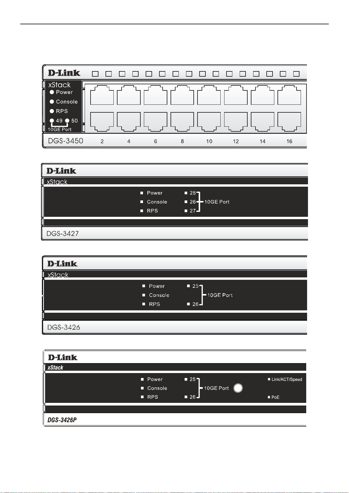
Front-Panel Components
The front panel of the Switch consists of LED indicators for Power, Master, Console, RPS, and for Link/Act for each port on the
Switch including 10GE Ports for optional modules and SFP port LEDs. The front panel includes a seven-segment LED indicating
the Stack ID number. A separate table below describes LED indicators in more detail. DGS-3426P also includes a Mode Select
button for changing the mode Link/Act/State to PoE.
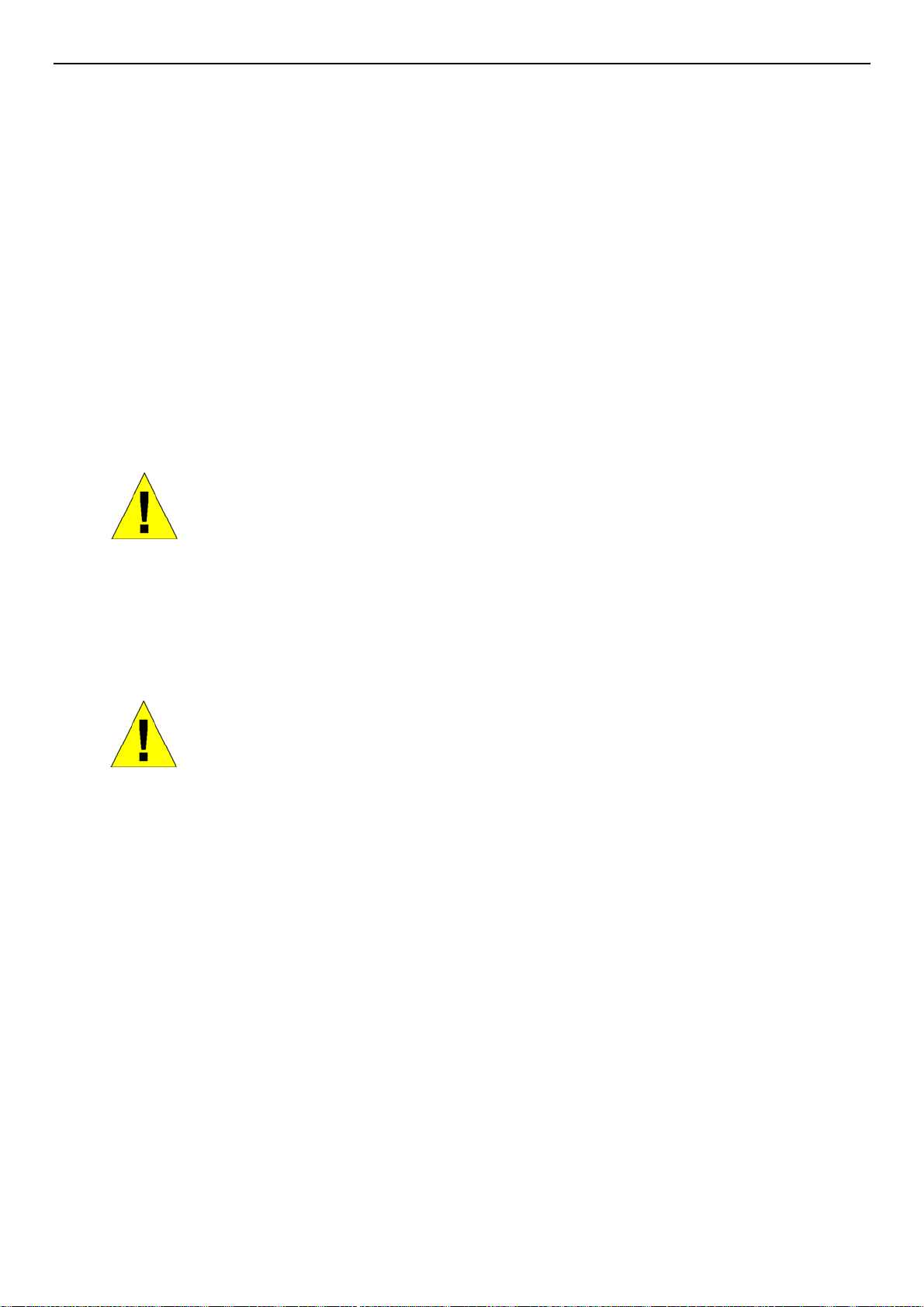
DGS-3426
Figure 2- 1. Front Panel View of the DGS-3426 as shipped
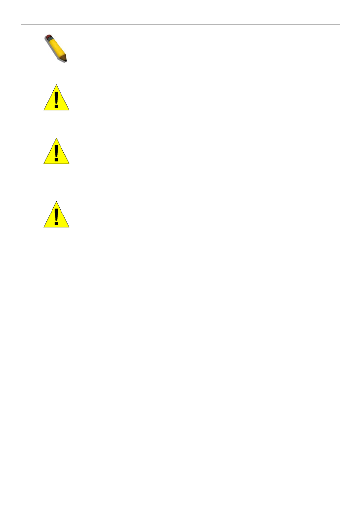
DGS-3426P
Figure 2- 2. Front Panel View of the DGS-3426P as shipped
DGS-3427
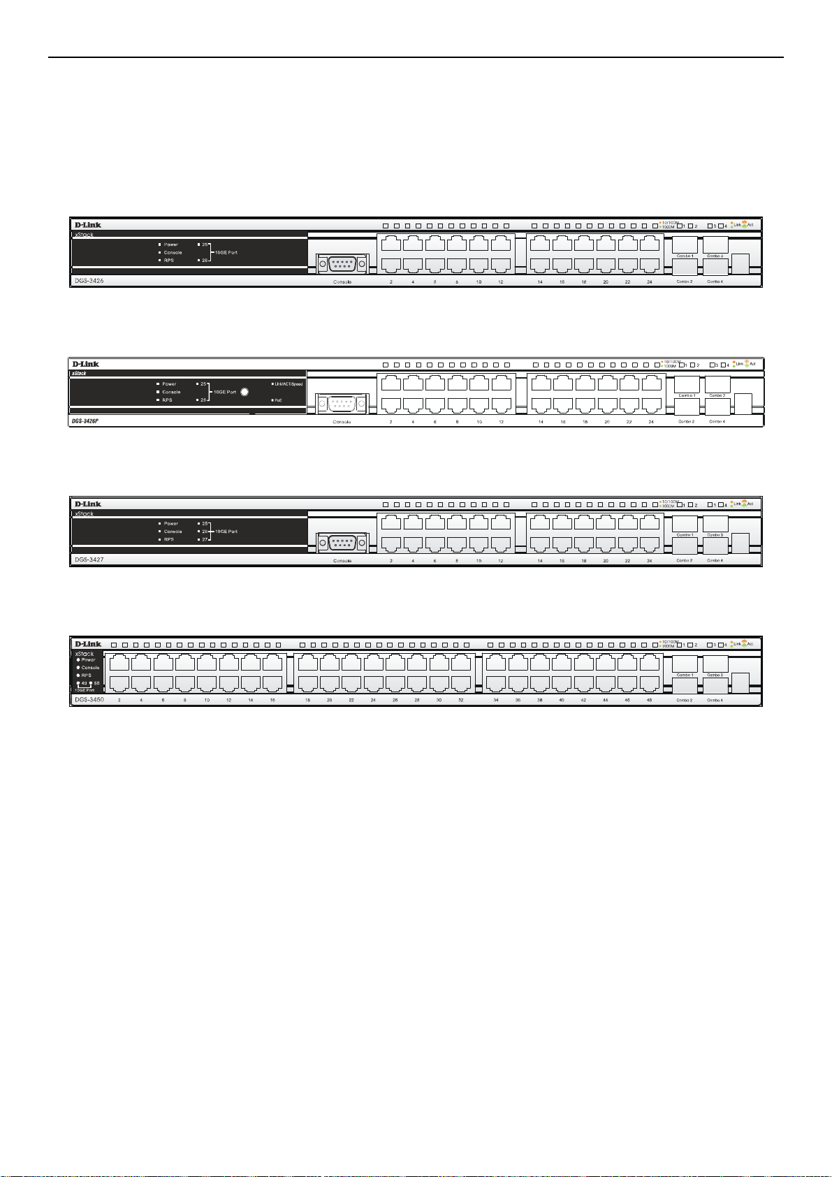
DGS-3450
Figure 2- 3. Front Panel View of the DGS-3427 as shipped
Figure 2- 4. Front Panel View of the DGS-3450 as shipped
4
Page 19
xStack DGS-3400 Series Layer 2 Gigabit Ethernet Managed Switch
LED Indicators
The Switch supports LED indicators for Power, Console, RPS and Port LEDs including 10GE port LEDs for optional module
inserts.
Figure 2- 5. LED Indicators on DGS-3450
Figure 2- 6. LED Indicators on DGS-3427
Figure 2- 7. LED Indicators on DGS-3426
Figure 2- 8. LED Indicators on DGS-3426P
5
Page 20

xStack DGS-3400 Series Layer 2 Gigabit Ethernet Managed Switch
LED Description
This LED will light green after powering the Switch on to indicate the ready state of the
Power
Console
device. The indicator is dark when the Switch is no longer receiving power (i.e powered
off).
This LED will blink green during the Power-On Self Test (POST). When the POST is
finished, the LED goes dark. The indicator will light steady green when an active console
link is in session via RS-232 console port.
RPS
Port LEDs
10GE Ports
Combo SFP Ports
Stack ID
Link/Act/Speed and
PoE (DGS-3426P only)
This LED will light when the internal power has failed and the RPS has taken over the
power supply to the Switch. Otherwise, it will remain dark.
One row of LEDs for each port is located above the ports on the front panel. The indicator
above the left side of a port corresponds to the port below the indicator in the upper row
of ports. The indicator above the right side of a port corresponds to the port below the
indicator in the lower row of ports. A steady green light denotes a valid 1000Mbps link on
the port while a blinking green light indicates activity on the port (at 1000Mbps). A steady
orange light denotes a valid 10 or 100Mbps link on the port while a blinking orange light
indicates activity on the port (at 100Mbps). These LEDs will remain dark if there is no
link/activity on the port.
A steady green light denotes a valid link on the port while a blinking green light indicates
activity on the port. These LEDs will remain dark if there is no link/activity on the port.
LED indicators for the Combo ports are located above the ports and numbered 1 – 4 for
Combo 1, Combo 2, etc. ports. A steady green light denotes a valid link on the port while
a blinking green light indicates activity on the port. These LEDs will remain dark if there is
no link/activity on the port.
These two seven segment LEDs display the current switch stack order of the Switch while
in use.
To change the LED mode from Link/Act/Speed to PoE and vice versa, press the LED
Mode Select Button. The Link/Act/Speed LED will light solid green when selected and will
shut off when PoE is selected. Likewise, when Link/Act/Speed is selected, the PoE LED
shuts off and the Link/Act/Speed LED lights solid green.
6
Page 21
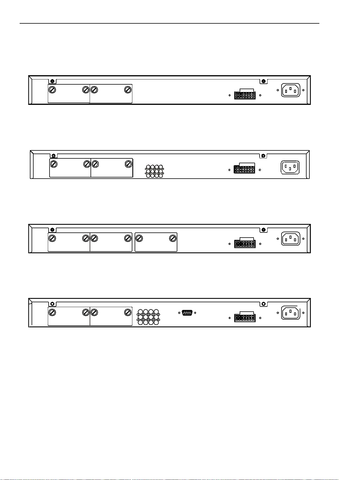
xStack DGS-3400 Series Layer 2 Gigabit Ethernet Managed Switch
Rear Panel Description
DGS-3426
The rear panel of the DGS-3426 contains an AC power connector, a r edundant power supply connector and two empty slots for
optional module inserts.
Figure 2- 9. Rear panel view of DGS-3426
DGS-3426P
The rear panel of the DGS-3426P contains an AC power connector, a redundant power supply connector, a heat vent for the rear
fan and two empty slots for optional module inserts.
Figure 2- 10. Rear panel view of the DGS-3426P
DGS-3427
The rear panel of the DGS-3427 contains an AC powe r connector, a redundant power supp ly connector and three empty slots fo r
optional module inserts.
Figure 2- 11. Rear panel view of DGS-3427
DGS-3450
The rear panel of the DGS-3450 contains an AC power connector, two empty slots for optional module inserts, a redundant power
supply connector, a RS-232 DCE console port for Switch management and a system fan vent.
Figure 2- 12. Rear panel view of DGS-3450
The AC power connector is a standard three-pronged connector th at supports the power cord. Plug-in the female conn ector of the
provided power cord into this socket, and the male sid e of the co rd into a power outlet. The Switch automatically adj usts its power
setting to any supply voltage in the range from 100 ~ 240 VAC at 50 ~ 60 Hz.
The rear panel also includes an outlet for an optional external power supply. When a power failure occurs, the optional external
RPS will automatically assume the power supply for the Switch immediately.
7
Page 22
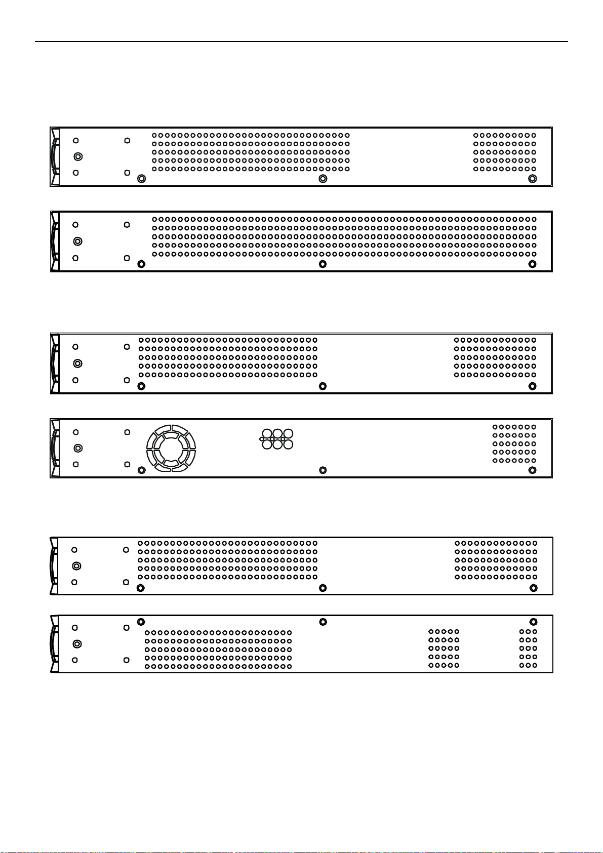
xStack DGS-3400 Series Layer 2 Gigabit Ethernet Managed Switch
Side Panel Description
The system fans and heat vents located on each side dissipate heat. Do not block these openings. Leave at least 6 inches of space
at the rear and sides of the Switch for proper ventilation. Be reminded that without proper heat dissipation and air circulation,
system components might overheat, which could lead to system failure and severely damage components.
Figure 2- 13. Side Panels (DGS-3450)
Figure 2- 14. Side Panels (DGS-3426 and DGS-3427)
Figure 2- 15. Side Panels of the DGS-3426P
8
Page 23

xStack DGS-3400 Series Layer 2 Gigabit Ethernet Managed Switch
Section 2
Installation
Package Contents
Installation Guidelines
Installing the Switch without the Rack
Rack Installation
Power On
The Optional Module
Redundant Power System
Package Contents
Open the shipping carton of the Switch and carefully unpack its contents. The carton should contain the following items:
1. One xStack Stackable Switch
2. One AC power cord
3. Mounting kit (two brackets and screws)
4. Four rubber feet with adhesive backing
5. RS-232 console cable
6. One CD Kit for User’s Guide/CLI/D-View module
7. One CD Kit for D-View 5.1 Standard version (for Europe only)
8. Registration card & China Warranty Card (for China only)
If any item is missing or damaged, please contact your local D-Link Reseller for replacement.
Installation Guidelines
Please follow these guidelines for setting up the Switch:
• Install the Switch on a sturdy, level surface that can support at least 6.6 lb. (3 kg) of weight. Do not place heavy objects on the
Switch.
• The power outlet should be within 1.82 m e t e rs (6 feet) of the Swit ch .
• Visually inspect the power cord and see that it is fully secured to the AC power port.
• Make sure that there is proper heat dissipation from and adequate ventilation around the Switch. Leave at least 10 cm (4
inches) of space at the front and rear of the Switch for ventilation.
• Install the Switch in a fairly cool and dry place for the acceptable temperature and humidity operating ranges.
• Install the Switch in a site free from strong electromagnetic field generators (such as motors), vibration, dust, and direct
exposure to sunlight.
• When installing the Switch on a level surface, attach the rubber feet to the bottom of the device. The rubber feet cushion the
Switch, protect the casing from scratches and prevent it from scratching other surfaces.
9
Page 24
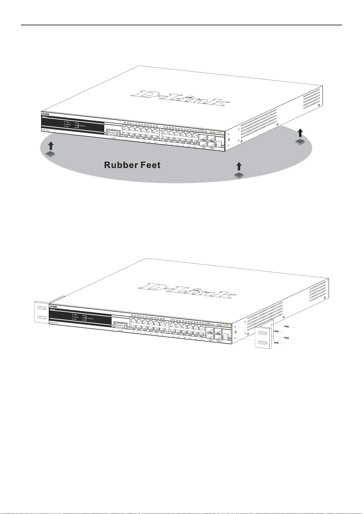
xStack DGS-3400 Series Layer 2 Gigabit Ethernet Managed Switch
Installing the Switch without the Rack
First, attach the rubber feet included with the Switch if installing on a desktop or shelf. Attach these cushioning feet on the bottom
at each corner of the device. Allow enough ventilation space between the Switch and any other objects in the vicinity.
Figure 2- 16. Prepare Switch for installation on a desktop or shelf
Installing the Switch in a Rack
The Switch can be mounted in a standard 19" rack. Use the following diagrams as a guide.
Figure 2- 17. Fasten mounting brackets to Switch
Fasten the mounting brackets to the Switch using the screws pr ovided. With the brackets attached securely, the Switch can be
mounted in a standard rack as shown below.
10
Page 25
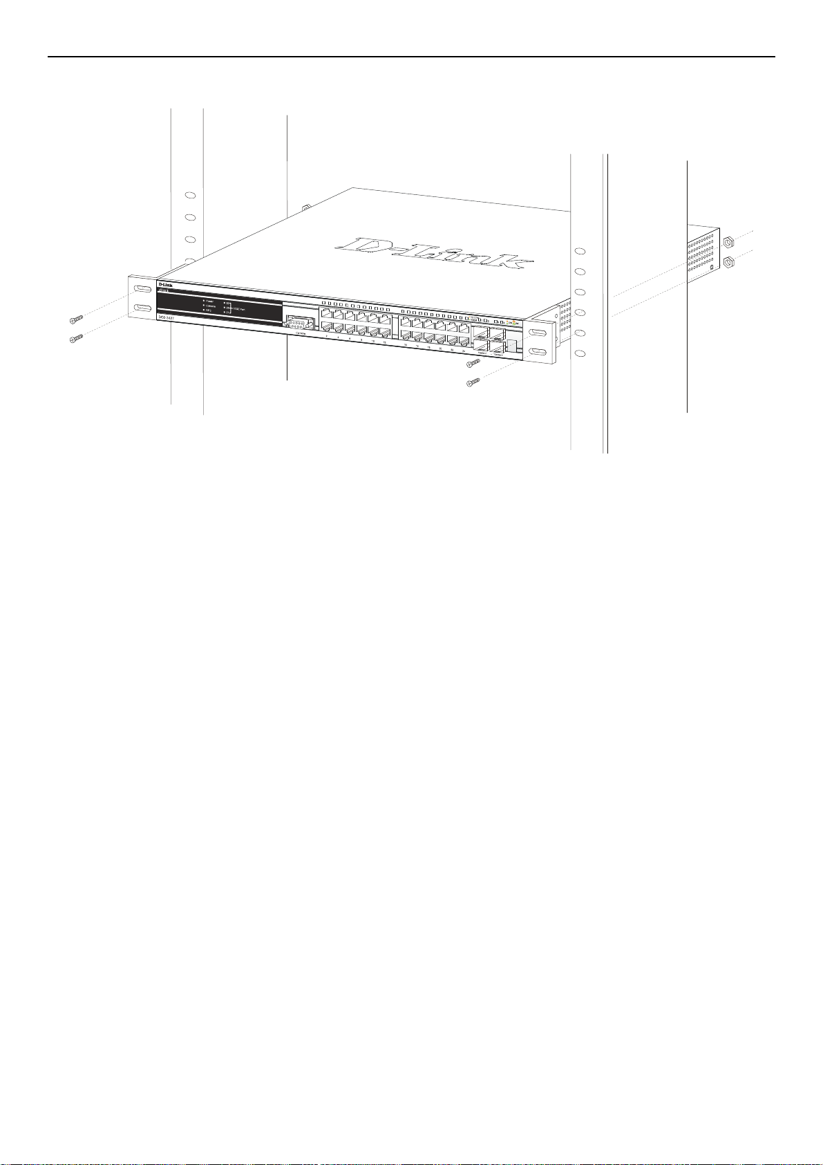
xStack DGS-3400 Series Layer 2 Gigabit Ethernet Managed Switch
Mounting the Switch in a Standard 19" Rack
Figure 2- 18. Installing Switch in a rack
Power On
1. Plug one end of the AC power cord into the power connector of the Switch and the other end into the local power source
outlet.
2. After powering on the Switch, the LED indicators will momentarily blink. This blinking of the LED indicators represents
a reset of the system.
Power Failure
As a precaution, in the event of a power failure, unplug the Switch. When power is resumed, plug the Switch back in.
11
Page 26
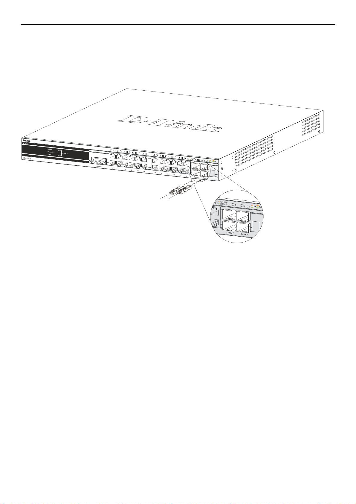
xStack DGS-3400 Series Layer 2 Gigabit Ethernet Managed Switch
Installing the SFP ports
The xStack DGS-3400 series switches are equipped with SFP (Small Form Factor Portable) ports, which are to be used with fiberoptical transceiver cabling in order to uplink various other networking devices for a gigabit link that may span great distances.
These SFP ports support full-duplex transmissions, have auto-negotiation and can be used with DEM-310GT (1000BASE-LX),
DEM-311GT (1000BASE-SX), DEM-314G T (1000BASE-LH) and DEM-315GT (1000BASE-ZX) transceivers. See the figure
below for installing the SFP ports in the Switch.
Figure 2- 19. Inserting the fiber-optic transceivers into the DGS-3426
12
Page 27
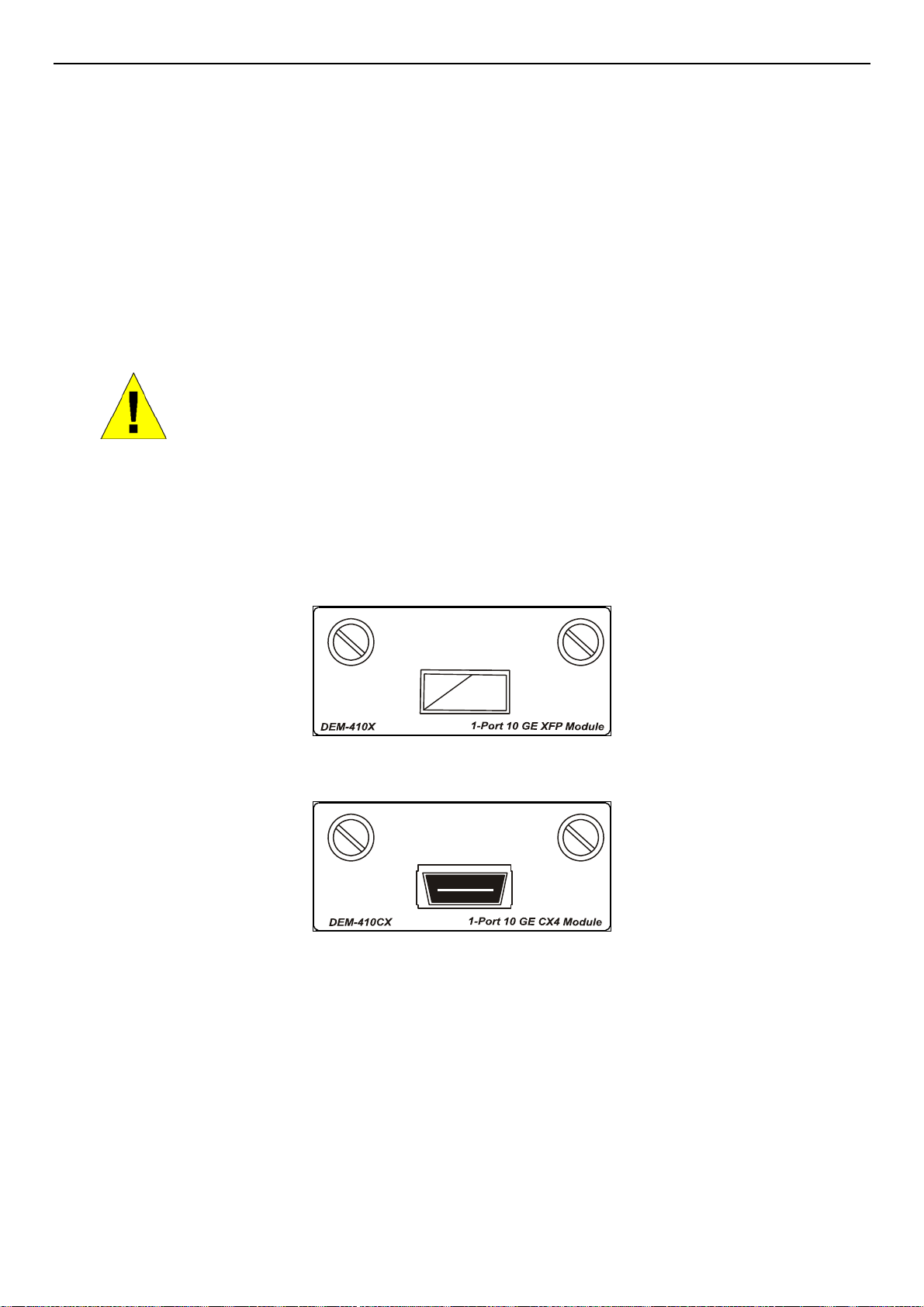
xStack DGS-3400 Series Layer 2 Gigabit Ethernet Managed Switch
The Optional Module
The rear panel of the DGS-3426, DGS-34 26P, DGS-3427 an d DGS-3 450 inclu de op en slots that may be equipp ed with the DE M410X 1-port 10GE XFP stacking uplink module, or a DEM-410CX 1-port 10GBASE-CX4 stacking uplink module, both sold
separately. These modules may be used to stack switches in a switch stack using a Duplex Ring or Duplex Chain topology.
Adding the DEM-410X optional module will allow the administrator to transmit data at a rate of ten gigabits a second. The
module port(s) are compliant with standard IEEE 802.3ae, support full-duplex transmissions only and must be used with XFP
MSA compliant transceivers.
The DEM-410CX uses copper wire medium, not optic fiber and therefore has a transmit length limit up to 1 meter. Compliant
with the IEEE802.3ak standard, this module uses a 4-laned copper connector for data transfer in full-duplex mode within a
stacking configuration.
To install these modules in the DGS-3400 Series Switch, follow the simple steps listed below.
CAUTION: Before adding the optional module, make sure to disconnect all power sources
connected to the Switch. Failure to do so may result in an electrical shock, which may cause
At the back of the Switch to the left is the slot for the optional module. This slot must be covered with the faceplate if the slot is
not being used. If a module will be installed in an available slot, the faceplate is easily removed by loosening the screws and
pulling off the plate.
damage, not only to the individual but to the Switch as well.
The front panels of the available modules are shown here:
Figure 2- 20. Front Panel of the DEM-410X
Figure 2- 21. Front Panel of the DEM-410CX
13
Page 28
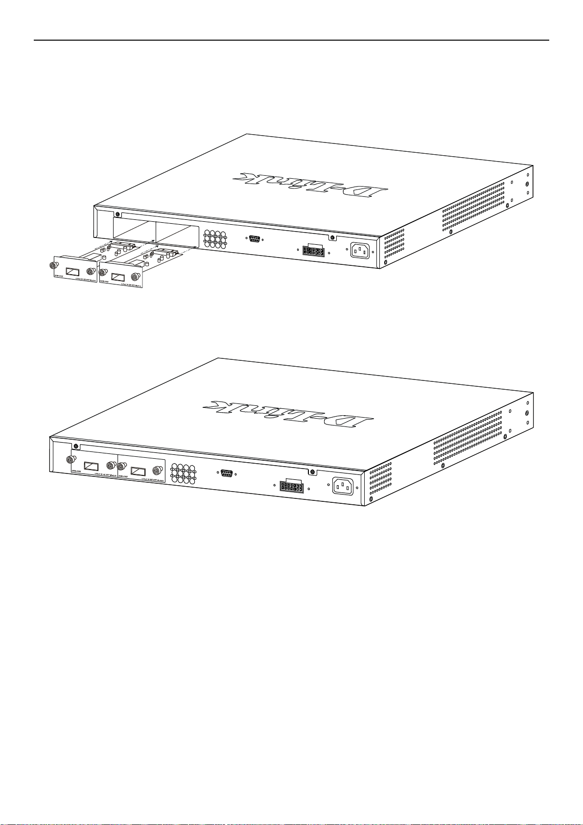
xStack DGS-3400 Series Layer 2 Gigabit Ethernet Managed Switch
Installing the Module
Unplug the Switch before removing the faceplate covering the empty slot. To install the module, slide it in to the available slot at
the rear of the Switch until it reaches the back, as shown in the following figure. Gently, but firmly push in on the module to
secure it to the Switch. The module should fit snugly into the corresponding receptors.
Figure 2- 22. Inserting the optional module into the Switch (DGS-3450)
Now tighten the two screws at adjacent ends of the module into the available screw holes on the Switch. The upgraded Switch is
now ready for use.
Figure 2- 23. DGS-3450 with optional DEM-410X module installed
14
Page 29
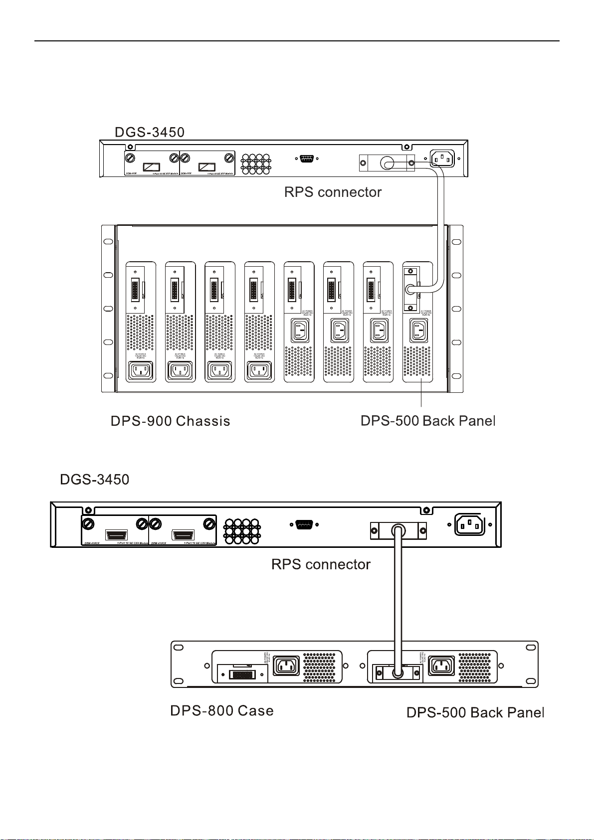
xStack DGS-3400 Series Layer 2 Gigabit Ethernet Managed Switch
External Redundant Power System
The Switch supports an external redundant power system. The diagrams below illustrate a proper RPS power conn ection to the
Switch. Please consult the documentation for information on power cabling and connectors and setup procedure.
Figure 2- 24. The DGS-3450 with the DPS-500 chassis RPS
Figure 2- 25. The DGS-3450 with the DPS-500 Redundant External Power Supply
15
Page 30

xStack DGS-3400 Series Layer 2 Gigabit Ethernet Managed Switch
Alternate to the other Switches in the xStack DGS-3400 Switch Series, the DGS-3426P utilizes the DPS-600 as its External
Redundant Power Supply. The DPS-600 is the ONLY RPS to be used with the DGS-3426P.
NOTE: See the DPS-500 or DPS-600 documentation for more information.
CAUTION: Do not use the Switch (except DGS-3426P) with any redundant power system
other than the DPS-500.
16
Page 31

xStack DGS-3400 Series Layer 2 Gigabit Ethernet Managed Switch
Section 3
Connecting the Switch
Switch to End Node
Switch to Switch
Connecting To Network Backbone or Server
NOTE: All high-performance N-Way Ethernet ports can support both MDI-II and MDI-X connections.
Switch to End Node
End nodes include PCs outfitted with a 10, 100 or 1000 Mbps RJ-45 Ethernet Network Interface Card (NIC) and routers.
An end node connects to the Switch via a twisted-pair UTP/STP cable. Connect the end node to any of the 1000BASE-T ports of
the Switch.
The Link/Act LEDs for each UTP port will light green or amber when the link is valid. A blinking LED indicates packet activity
on that port.
Switch to Switch
There is a great deal of flexibility on how connections are made using the appropriate cabling.
• Connect a 10BASE-T hub or switch to the Switch via a twisted-pair Category 3, 4 or 5 UTP/STP cable.
• Connect a 100BASE-TX hub or switch to the Switch via a twisted-pair Category 5 UTP/STP cable.
• Connect 1000BASE-T switch to the Switch via a twisted pair Category 5e UTP/STP cable.
• Connect 10G optional module ports at the rear of the device using CX4 or fiber-optic cables
• Connect switch supporting a fiber-optic uplink to the Switch’s SFP ports via fiber-optic cabling. See cabling guidelines in
Appendix B for more information.
Figure 3- 1. Connect the Switch to a port on a switch with straight or crossover cable
Figure 3- 2. Connect the Switch utilizing the 10G optional modules at the rear of the Switch.
17
Page 32

xStack DGS-3400 Series Layer 2 Gigabit Ethernet Managed Switch
Connecting To Network Backbone or Server
The combo SFP ports and the 1000BASE-T ports are ideal for uplinking to a network backbone, server or server farm. The copper
ports operate at a speed of 1000, 100 or 10Mbps in full or half duplex mode. The fiber-optic ports can operate at 1000Mbps in full
duplex mode only.
Connections to the Gigabit Ethernet ports are made using a fiber-optic cable or Category 5e copper cable, depending on the type
of port. A valid connection is indicated when the Link LED is lit.
Figure 3- 3. DGS-3400 uplink connection to a server, PC or switch stack.
18
Page 33

xStack DGS-3400 Series Layer 2 Gigabit Ethernet Managed Switch
Section 4
Introduction to Switch Management
Management Options
Connecting the Console Port (RS-232 DCE)
First Time Connecting to the Switch
Password Protection
SNMP Settings
IP Address Assignment
Connecting Devices to the Switch
Management Options
This system may be managed out-of-band through the console port on the front panel or in-band using Telnet. The user may also
choose the web-based management, accessible through a web browser.
1. Web-based Management Interface
After successfully installing the Switch, the user can configure the Switch, monitor the LED panel, and display statistics
graphically using a web browser, such as Netscape Navigator (version 6.2 and higher) or Microsoft® Internet Explorer
(version 5.0 and higher).
2. SNMP-Based Management
The Switch can be managed with an SNMP-compatible console program. The Switch supports SNMP version 1.0,
version 2.0 and version 3.0. The SNMP agent decodes the incoming SNMP messages and responds to requests with MIB
objects stored in the database. The SNMP agent updates the MIB objects to generate statistics and counters.
3. Command Line Console Interface through the Serial Port
The user can also connect a computer or terminal to the serial console port to access the Switch. The command-linedriven interface provides complete access to all Switch management features.
19
Page 34

xStack DGS-3400 Series Layer 2 Gigabit Ethernet Managed Switch
Connecting the Console Port (RS-232 DCE)
The Switch provides an RS-232 serial port that enables a connection to a computer or terminal for monitoring and configuring the
Switch. This port is a female DB-9 connector, implemented as a data terminal equipment (DTE) connection.
To use the console port, the following equipment is needed:
• A terminal or a computer with both a serial port and the ability to emulate a terminal.
• A null modem or crossover RS-232 cable with a female DB-9 connector for the console port on the Switch.
To connect a terminal to the console port:
Connect the female connector of the RS-232 cable directly to the console port on the Switch, and tighten the captive retaining
screws.
Connect the other end of the cable to a terminal or to the serial connector of a computer running terminal emulation software. Set
the terminal emulation software as follows:
• Select the appropriate serial port (COM port 1 or COM port 2).
• Set the data rate to 115200 baud.
• Set the data format to 8 data bits, 1 stop bit, and no parity.
• Set flow control to none.
• Under Properties, select VT100 for Emulation mode.
• Select Terminal keys for Function, Arrow and Ctrl keys. Make sure to use Terminal keys (not Windows keys) are selected.
NOTE: When using HyperTerminal with the Microsoft® Windows® 2000 operating system, ensure
that Windows 2000 Service Pack 2 or later is installed. Windows 2000 Service Pack 2 allows use
of arrow keys in HyperTerminal's VT100 emulation. See www.microsoft.com for information on
Windows 2000 service packs.
• After you have correctly set up the terminal, plug the power cable into the power receptacle on the back of the Switch. The
boot sequence appears in the terminal.
• After the boot sequence completes, the console login screen displays.
• If the user has not logged into the command line interface (CLI) program, press the Enter key at the User name and password
prompts. There is no default user name and password for the Switch. The administrator must first create user names and
passwords. If user accounts have been previously set up, log in and continue to configure the Switch.
• Enter the commands to complete desired tasks. Many commands require administrator-level access privileges. Read the next
section for more information on setting up user accounts. See the xStack DGS-3400 series CLI Manual on the documentation
CD for a list of all commands and additional information on using the CLI.
• To end a management session, use the logout command or close the emulator program.
If problems occur in making this connection on a PC, make sure the emulation is set to VT-100. The emulation settings can be
configured by clicking on the File menu in the HyperTerminal window by clicking on Properties in the drop-down menu, and
then clicking the Settings tab. This is where you will find the Emulation options. If you still do not see anything, try rebooting
the Switch by disconnecting its power supply.
20
Page 35

xStack DGS-3400 Series Layer 2 Gigabit Ethernet Managed Switch
Once connected to the console, the screen below will appear on the console screen. This is where the user will enter commands to
perform all the available management functions. The Switch will prompt the user to enter a user name and a password. Upon the
initial connection, there is no user name or password and therefore just press enter twice to access the command line interface.
DGS-3427 Gigabit Ethernet Switch
Command Line Interface
Firmware: Build 2.35-B09
Copyright(C) 2008 D-Link Corporation. All rights reserved.
UserName:
Figure 4- 1. Initial Screen after first connection
Managing the Switch for the First Time
The Switch supports user-based security that can allow prevention of unauthorized users from accessing the Switch or changing
its settings. This section tells how to log onto the Switch via out-if-band console connection.
NOTE: The passwords used to access the Switch are case-sensitive; for example, "S"
is not the same as "s."
NOTE: Press Ctrl+R to refresh the screen. This command can be used at any time to
force the console program in the Switch to refresh the console screen.
Press Enter in both the Username and Password fields. Then access will be given to enter commands after the command prompt
DGS-3426:4#, DGS-3426P:4#, DGS-3427:4# or DGS-3450:4# as shown below:
DGS-3427 Gigabit Ethernet Switch
Command Line Interface
Firmware: Build 2.35-B09
Copyright(C) 2008 D-Link Corporation. All rights reserved.
UserName:
PassWord:
DGS-3427:4#_
Figure 4- 2. Initial screen, first time connecting to the Switch
21
Page 36

xStack DGS-3400 Series Layer 2 Gigabit Ethernet Managed Switch
Press Enter in both the Username and Password fields. Then access will be given to enter commands after the command prompt
DGS-3426:4#, DGS-3426P:4#, DGS-3427:4# or DGS-3450:4# as shown below:
There is no initial username or password. Leave the Username and Password fields blank.
NOTE: The first user automatically gets Administrator level privileges. At least one Admin-level
user account must be created for the Switch.
Password Protection
The xStack DGS-3400 Series switches do not have a default user name and password. One of the first tasks when settings up the
Switch is to create user accounts. Logging in using a predefined administrator-level user name will give the user privileged access
to the Switch's management software.
After the initial login, define new passwords for both default user names to prevent unauthorized access to the Switch, and record
the passwords for future reference.
To create an administrator-level account for the Switch, do the following:
1. At the CLI login prompt, enter create account admin followed by the <user name> and press the Enter key.
2. The Switch will then prompt the user to provide a password. Type the <password> used for the administrator
account being created and press the Enter key.
3. Once entered, the Switch will again ask the user to enter the same password again to verify it. Type the same
password and press the Enter key.
4. A “Success” response by the Switch will verify the creation of the new administrator.
NOTE: Passwords are case sensitive. User names and passwords can be up
to 15 characters in length.
The sample below illustrates a successful creation of a new administrator-level account with the user name "newmanager".
DGS-3427:4#create account admin newmanager
Command: create account admin newmanager
Enter a case-sensitive new password:***
Enter the new password again for confirmation:***
Success.
DGS-3427:4#_
Figure 4- 3. Creating an Account on the Switch
NOTICE: CLI configuration commands only modify the running configuration file and are not
saved when the Switch is rebooted. To save all configuration changes in non-volatile memory,
use the save command to copy the running configuration file to the startup configuration.
22
Page 37

xStack DGS-3400 Series Layer 2 Gigabit Ethernet Managed Switch
SNMP Settings
Simple Network Management Protocol (SNMP) is an OSI Layer 7 (Application Layer) designed specifically for managing and
monitoring network devices. SNMP enables network management stations to read and modify the settings of gateways, routers,
switches and other network devices. Use SNMP to configure system features for proper operation, monitor performance and
detect potential problems in the Switch, switch group or network.
Managed devices that support SNMP include software (referred to as an agent), which runs locally on the device. A defined set of
variables (managed objects) is maintained by the SNMP agent and used to manage the device. These objects are defined in a
Management Information Base (MIB), which provides a standard presentation of the information controlled by the on-board
SNMP agent. SNMP defines both the format of the MIB specifications and the protocol used to access this information over the
network.
The xStack DGS-3400 series switches support SNMP versions 1, 2c, and 3. The administrator may specify which version of
SNMP to use to monitor and control the Switch. The three versions of SNMP vary in the level of security provided between the
management station and the network device.
In SNMP v.1 and v.2, user authentication is accomplished using 'community strings', which function like passwords. The remote
user SNMP application and the Switch SNMP must use the same community string. SNMP packets from any station that has not
been authenticated are ignored (dropped).
The default community strings for the Switch used for SNMP v.1 and v.2 management access are:
• public - Allows authorized management stations to retrieve MIB objects.
• private - Allows authorized management stations to retrieve and modify MIB objects.
SNMP v.3 uses a more sophisticated authentication process that is separated into two parts. The first part is to maintain a list of
users and their attributes that are allowed to act as SNMP managers. The second part describes what each user on that list can do
as an SNMP manager.
The Switch allows groups of users to be listed and configured with a shared set of privileges. The SNMP version may also be set
for a listed group of SNMP managers. Thus, a group of SNMP managers can be created to view read-only information or receive
traps using SNMP v.1 while assigning a high e r level of sec u ri t y to another group, granting read/write pri vi le ges usi n g SNM P v.3.
Using SNMP v.3 individual users or groups of SNMP managers can be allowed to perform or be restricted from performing
specific SNMP management functions. The functions allowed or restricted are defined using the Object Identifier (OID)
associated with a specific MIB. An additional layer of security is available for SNMP v.3 in that SNMP messages may be
encrypted. To read more about how to configure SNMP v.3 settings for the Switch read the section entitled Management.
Traps
Traps are messages that alert network personnel of events that occur on the Switch. The events can be as serious as a reboot
(someone accidentally turned OFF the Switch), or less serious like a port status change. The Switch generates traps and sends
them to the trap recipient (or network manager). Typical traps include trap messages for Auth entication Failure, Topolog y Chang e
and Broadcast\Multicast Storm.
MIBs
The Switch in the Management Information Base (MIB) stores management and counter information. The Switch uses the
standard MIB-II Management Information Base module. Consequently, values for MIB objects can be retrieved from any SNMPbased network management software. In addition to the standard MIB-II, the Switch also supports its own proprietary enterprise
MIB as an extended Management Information Base. The proprietary MIB may also be retrieved by specifying the MIB Object
Identifier. MIB values can be either read-only or read-write.
23
Page 38

xStack DGS-3400 Series Layer 2 Gigabit Ethernet Managed Switch
IP Address Assignment
An IP Address must be assigned to each switch, which is used for communication with an SNMP network manager or other
TCP/IP application (for example BOOTP, TFTP). The Switch's default IP address is 10.90.90.90. The user may change the default
Switch IP address to meet the specification of your networking address scheme.
The Switch is also assigned a unique MAC address by the factory. This MAC address cannot be changed, and can be found by
entering the command "show switch" into the command line interface, as shown below.
Device Type : DGS-3427 Gigabit Ethernet Switch
Unit ID : 1
MAC Address : 00-19-5B-EF-6F-21
IP Address : 10.73.21.35 (Manual)
VLAN Name : default
Subnet Mask : 255.0.0.0
Default Gateway : 0.0.0.0
Boot PROM Version : Build 1.00-B13
Firmware Version : Build 2.35-B09
Hardware Version : 2A1G
System Name :
System Location :
System Contact :
Spanning Tree : Disabled
GVRP : Disabled
IGMP Snooping : Disabled
MLD Snooping : Disabled
TELNET : Enabled (TCP 23)
WEB : Enabled (TCP 80)
RMON : Disabled
SSL status : Disabled
SSH status : Disabled
CTRL+C ESC q Quit SPACE n Next Page ENTER Next Entry a All
Figure 4- 4. “show switch” command
The Switch's MAC address also appears in Switch Information menu of the web-based management interface. The IP address for
the Switch must be set before using the Web-based manager. The Switch IP address can be automatically set using BOOTP or
DHCP protocols, in which case the actual address assigned to th e Switch must be known. The IP address may be set using the
Command Line Interface (CLI) over the console serial port as follows:
Starting at the command line prompt, enter the command:
config ipif System ipaddress xxx.xxx.xxx.xxx/yyy.yyy.yyy.yyy
Where the x's represen t the IP address to be assigned to th e IP interface named System and the y's represent the correspond ing
subnet mask. Alternatively, the user can enter config ipif System ipaddress xxx.xxx.xxx.xx x/z. Where the x's represent the IP
address to be assigned to the IP interface named System and the z represents the corresponding number of subnets in CIDR
notation. The IP interface named System on the Switch can be assigned an IP address and subnet mask, which can then be used to
connect a management station to the Switch's Telnet or Web-based management agent.
24
Page 39

xStack DGS-3400 Series Layer 2 Gigabit Ethernet Managed Switch
DGS -3426:4#config ipif System ipaddress 10.73.21.35/255.0.0.0
Comand: config ipif System ipaddress 10.73.21.35/8
Success.
DGS -3426:4#
Figure 4- 5. Assigning the Switch an IP Address
In the above example, the Switch was assigned an IP address of 10.53.13.26 with a subnet mask of 255.0.0.0 . Th e system message
Success indicates that the command was executed successfully. The Switch can now be configured and managed via Telnet and
the CLI or via the Web-based management.
NOTE: The DGS-3400 series of switches have the capability to be configured for an IP address of
0.0.0.0, or, in essence, have no IP address. This function maybe used to disable Layer 3 functions
of the Switch. When the IP address is set to 0.0.0.0 (invalid IP address), the Switch can only be
managed through the console port or SIM. Other management applications such as Telnet, Webbased and SNMP cannot be used to manage the Switch when its IP address is 0.0.0.0.
25
Page 40

xStack DGS-3400 Series Layer 2 Gigabit Ethernet Managed Switch
Web-based Switch Configuration
Introduction
Logging on to the Web Manager
Web-Based User Interface
Basic Setup
Reboot
Basic Switch Setup
Network Management
Switch Utilities
Network Monitoring
IGMP Snooping Status
Section 5
Introduction
All software functions of the xStack DGS-3400 switch series can be managed, configured and monitored via the embedded webbased (HTML) interface. Manage the Switch from remote stations anywhere on the network through a standard browser. The
browser acts as a universal access tool and can communicate directly with the Switch using the HTTP protocol.
The Web-based management module and the Console program (and Telnet) are different ways to access the same internal
switching software and configure it. Thus, all settings encountered in web-based management are the same as those found in the
console program.
Logging in to the Web Manager
To begin managing the Switch, simply run the browser installed on your computer and point it to the IP address you have defined
for the device. The URL in the address bar should read something like: http://123.123.123.123, where the numbers 123 represent
the IP address of the Switch.
NOTE: The factory default IP address is 10.90.90.90.
This opens the management module's user authentication window, as seen below.
26
Page 41

xStack DGS-3400 Series Layer 2 Gigabit Ethernet Managed Switch
Figure 5- 1. Enter Network Password window
Leave both the User Name field and the Password field blank and click OK. This will open the Web-based user interface. The
Switch management features available in the web-based manager are explained below.
Web-based User Interface
The user interface provides access to various Switch configuration and management screens, allows the user to view performance
statistics, and permits graphical monitoring of the system status.
Areas of the User Interface
The figure below shows the user interface. Three distinct areas divide the user interface, as described in the table.
27
Page 42

xStack DGS-3400 Series Layer 2 Gigabit Ethernet Managed Switch
Area 2
Area 1
Area Function
Area 1
Area 2
Select the menu or window to display. Open folders and click the hyperlinked menu buttons and
subfolders contained within them to display menus. Click the D-Link logo to go to the D-Link website.
Presents a graphical near real-time image of the front panel of the Switch. This area displays the
Switch's ports and expansion modules, showing port activity, duplex mode, or flow control,
depending on the specified mode.
Area 3
Figure 5- 2. Main Web-Manager Screen
Some management functions, including port configuration are accessible here.
Area 3
Presents switch information based on user selection and the entry of configuration data.
Web Pages
When connecting to the management mode of the Switch with a web browser, a login screen is displayed. Enter a user name and
password to access the Switch's management mode.
Below is a list of the main folders available in the web interface:
Administration – Contains the following menu pages and sub-directories: IP Address, Interface Settings, Stacking, Port
Configuration, User Accounts, Port Mirroring, System Log, System Severity Settings, SNTP Settings, MAC Notification Settings,
TFTP Services, Multiple Image Services, Ping Test, Safeguard Engine, Static ARP Settings, IPv6 Neighbor, Routing Table,
DHCP/BOOTP Relay, DHCP Auto Configuration, SNMP Manager, IP-MAC-Port Binding, PoE, and Single IP Management
Settings.
28
Page 43

xStack DGS-3400 Series Layer 2 Gigabit Ethernet Managed Switch
L2 Features – Contains the following menu pages and sub-directories: VLAN, Trunking, IGMP Snooping, MLD Snooping,
Loopback Detection Global Settings, Spanning Tree and Forwarding & Filtering.
QoS – Contains the following menu pages and sub-directories: Bandwidth Control, QoS Scheduling Mechanism, QoS Output
Scheduling, 802.1p Default Priority and 802.1p User Priority.
ACL – Contains the following menu pages and sub-directories: Time Range, Access Profile Table and CPU Interface Filtering.
Security – Contains the following menu pages and sub-directories: Authorization Network State Settings, Traffic Control, Port
Security, 802.1X, Trust Host, Access Authentication Control, MAC Based Access Control, Traffic Segmentation, SSL, SSH and
JWAC.
Monitoring – Contains the following menu pages and sub-directories: Device Status, Stacking Information, Module Information,
CPU Utilization, Port Utilization, Packets, Errors, Packet Size, Browse Router Port, Browse MLD Router Port, VLAN Status,
VLAN Status Port, Port Access Control, MAC Address Table, IGMP Snooping Group, MLD Snooping Group, Switch Logs,
Browse ARP Table, Session Table, IP Forwarding Table, Browse Routing Table and MAC Based Access Control Authentication
Status.
Save Services – Contains the following menu pages and sub-directories: Save Changes, Configure Information and Current
Configuration Settings.
Reset, Reboot System and Logout menu links are displayed in the main directory.
NOTE: Be sure to configure the user name and password in the User
Accounts menu before connecting the Switch to the greater network.
29
Page 44

xStack DGS-3400 Series Layer 2 Gigabit Ethernet Managed Switch
Configuring the Switch
DGS-3400 Web Management Tool
IP Address
Interface Settings
Stacking
Port Configuration
User Accounts
Port Mirroring
System Log
System Severity Settings
SNTP Settings
MAC Notification Settings
TFTP Services
Section 6
Multiple Image Services
Ping Test
Safeguard Engine
Static ARP Settings
IPv6 Neighbor
Routing Table
DHCP/BOOTP Relay
DHCP Auto Configuration
SNMP Manager
IP-MAC-Port Binding
PoE
Single IP Management Settings
30
Page 45

xStack DGS-3400 Series Layer 2 Gigabit Ethernet Managed Switch
Device Information
The Device Information window contains the main
settings for all major functions for the Switch. It appears
automatically when you log on to the Switch. To return
to the Device Information window after viewing other
windows, click the DGS-3400 Web Management Tool
folder. The Device Information window shows the
Switch’s MAC Address (assigned by the factory and
unchangeable), the Boot PROM, Firmware Version,
Hardware Version and Serial Number. This
information is helpful to keep track of PROM and
firmware updates and to obtain the Switch's MAC
address for entry into another network device's address
table, if necessary. The user may also enter a System
Name, System Location and System Contact to aid in
defining the Switch, to the user's preference. In addition,
this screen displays the status of functions on the Switch
to quickly assess their current global status. Some
Functions are hyper-linked for easy access from the
Device Information window.
Many miscellaneous functions are enabled and disabled
in the Device Information menu.
NOTE: DGS-3426/DGS3427/DGS-3450/DGS-3426P
will display the serial number in
the Device Information window
for Firmware 2.35.B09.
Figure 6- 1. Device Information window
Device Information menu configurable parameters include those described in the table below.
Parameter Description
System Name
Enter a system name for the Switch, if so desired. This name will identify it in the Switch
network.
System Location
System Contact
Serial Port Auto
Logout Time
Serial Port Baud
Rate
MAC Address
Aging Time
Enter the location of the Switch, if so desired.
Enter a contact name for the Switch, if so desired.
Select the logout time used for the console interface. This automatically logs the user out after
an idle period of time, as defined. Choose from the following options: 2 Minutes, 5 Minutes, 10
Minutes, 15 Minutes or Never. The default setting is 10 minutes.
This field specifies the baud rate for the serial port on the Switch. The default setting is 115200.
This field specifies the length of time a learned MAC Address will remain in the forwarding table
without being accessed (that is, how long a learned MAC Address is allowed to remain idle). To
change this, type in a different value representing the MAC address age-out time in seconds.
The MAC Address Aging Time can be set to any value between 10 and 1,000,000 seconds. The
31
Page 46

xStack DGS-3400 Series Layer 2 Gigabit Ethernet Managed Switch
default setting is 300 seconds.
IGMP Snooping
IGMP Multicast
Router Only
MLD Snooping
MLD Multicast
Router Only
GVRP Status
Telnet Status
Telnet TCP Port
Number (1-65535)
Web Status
To enable system-wide IGMP Snooping capability, select Enabled. IGMP snooping is Disabled
by default. Enabling IGMP snooping allows the user to specify use of a multicast router only
(see below). To configure IGMP Snooping for individual VLANs, use the IGMP Snooping
window under the IGMP Snooping folder.
This field specifies that the Switch should only forward all multicast traffic to a multicast-enabled
router, if enabled. Otherwise, the Switch will forward all multicast traffic to any IP router. The
default is Disabled.
To enable system-wide MLD Snooping capability, select Enabled. MLD snooping is Disabled by
default. Enabling MLD snooping allows you to specify use of a multicast router only (see below).
To configure MLD Snooping for individual VLANs, use the MLD Snooping window under the
MLD Snooping folder.
This field specifies that the Switch should only forward all multicast traffic to a multicast-enabled
router, if enabled. Otherwise, the Switch will forward all multicast traffic to any IP router. The
default is Disabled.
Use this pull-down menu to enable or disable GVRP on the Switch.
Telnet configuration is Enabled by default. If you do not want to allow configuration of the
system through Telnet choose Disabled.
The TCP port number used for Telnet management of the Switch. The "well-known" TCP port for
the Telnet protocol is 23.
Web-based management is Enabled by default. If you choose to disable this by selecting
Disabled, you will lose the ability to configure the system through the web interface as soon as
these settings are applied.
Web TCP Port
Number (1-65535)
RMON Status
Link Aggregation
Algorithm
Switch 802.1X
Auth Protocol
HOL Prevention
Jumbo Frame
The TCP port number used for Web-based management of the Switch. The "well-known" TCP
port for the Telnet protocol is 80.
Remote monitoring (RMON) of the Switch is Enabled or Disabled here.
The algorithm that the Switch uses to balance the load across the ports that make up the port
trunk group is defined by this definition. Choose MAC Source, MAC Destination, MAC Src &
Dest, IP Source, IP Destination or IP Src & Dest (See the Link Aggregation section of this
manual).
MAC Address may enable by port or the Switch’s 802.1X function; the default is Disabled. This
field must be enabled to view and configure certain windows for 802.1X. More information
regarding 802.1X, its functions and implementation can be found later in this section, under the
Port Access Entity folder.
Port-Based 802.1X specifies that ports configured for 802.1X are initialized based on the port
number only and are subject to any authorization parameters configured.
MAC-based Authorization specifies that ports configured for 802.1X are initialized based on the
port number and the MAC address of the computer being authorized and are then subject to any
authorization parameters configured.
The user may use the pull-down menu to choose between RADIUS EAP and Local for the
802.1X authentication protocol on the Switch. The default setting is RADIUS EAP.
If this option is enabled it prevents the forwarding of data to a port that is blocked. Traffic that
would normally be sent to the buffer memory of the Switch’s TX queue is dropped so that
memory usage is conserved and performance across all ports remains high.
This field will enable or disable the Jumbo Frame function on the Switch. The default is
Disabled. Max. Jumbo frame size = 9216 bytes if this is enabled.
Syslog State
ARP Aging time
Click Apply to implement changes made.
The user may globally enable or disable the Syslog function here by using the pull-down menu.
The default is Disabled.
The user may set the ARP Aging Time here by entering a time between 0 and 65535 minutes.
The default setting is 20 minutes.
32
Page 47

xStack DGS-3400 Series Layer 2 Gigabit Ethernet Managed Switch
IPv6
The xStack DGS-3400 has the capability to support the following:
• IPv6 unicast, multicast and anycast addresses
• Allow for IPv6 packet forwarding
• IPv6 fragmentation and re-assembly
• Processing of IPv6 packet and extension headers
• Static IPv6 route configuration
• IPv6 Neighbor Discovery
• Link-Layer Address resolution, Neighbor Unreachability Detection and Duplicate Address Detection over broadcast
mediums (ex: Ethernet)
• Send Router Advertisement
• ICMPv6 functionality
The following sections will briefly explain IPv6, its functionality and how IPv6 is implemented on this Switch.
Overview
IP version 6 is the logical successor to IP version 4. It was known that IPv4 could not support the amount of addresses that would
eventually be needed for not only each person, but each device that would require an IP address, and therefore a system with a
larger pool of IP addresses was r equired. IPv6 has addressed that issue, along with other issues that enhance routing over the
network, provide better security and improve Quality of Service for Internet users. Some of the improvements made were:
Expanding the Capabilites for IP Addressing – IPv6 has increased the size of the IP address from 32 bits to 128 bits. As a result,
the addressing hierarchy has been greatly expanded, more nodes now have the capability of having a uniqu e IP address and the
method of assigning an IP address to an interface has become cleaner and quicker. Unicast and multicast addresses still exist but
in a purer form and multicast addresses now have a scope field which increases the scalability of multicast routing. Also, an
anycast address has been added, which will send packets to the closest node which is a part of a group of nodes, thereby
eliminating a specified device for a particular group.
Simplifying the Packet Header – The IPv6 packet header has been simplified from IPv4 as some headers have been modified or
dropped altogether, which improves processing speed and cost. The IPv6 header now has a fixed length of 40 bytes consisting of
an 8-byte header and two 16-byte IP addresses (source and destination).
Extensions and Options Enhancement – Packet header option fields encoding has been enhanced to allow for proficient
forwarding of packets due to lesser restrictions on packet option length and encoding method. This enhancement will also allow
new option fields to be integrated into the IPv6 system without hassles and limitations. These optional headers are placed between
the header and the payload of a packet, if they are necessary at all.
Authentication and Privacy Extension Support – New authentication capabilities use extensions for data integrity and data
confidentiality for IPv6.
Flow Labeling – This new capability allows packets to be streamlined into certain traffic “flows” if labeled by the sender. In this
way, services such as “real time services or non-default quality of service can receive special attention for improved flow quality.
33
Page 48

xStack DGS-3400 Series Layer 2 Gigabit Ethernet Managed Switch
Packet Format
As in IPv4, the IPv6 packet consists of the packet header and the payload, but the difference occurs in the packet header which has
been amended and improved for better packet flow and processing. The following will outline and detail the IPv6 enhancements
and parts of the IPv6 packet, with special attention to the packet header.
IPv6 Header
The IPv6 packet header has been modified and simplified from IPv4. The header length, identification, flags, fragment offset and
header checksum have all been removed in the IPv6 header due to lack of necessity or improvement to a better function of the
header. The minimum header length is now 20 bytes but may be increased to as much as 60 bytes, using 4-byte increment
extensions. The following picture is an example of an IPv6 packet header.
Eight fields make up the basic IPv6 packet header:
Version – This 4-bit field defines the packet version, which is IPv6 and is defined as the number 6.
Traffic Class – This 1-byte field replaces the Type of Service field used in IPv4 and is used to process real-time data and other
data requiring special packet management. This field defines the Class of Service priority of an IPv6 packet.
Flow Label – This 20-bit field is used to facilitate the handling of real-time traffic. Hosts sending data can place a flow label into
this field to identify a sequence of packets that have an identical set of options. In this way, router can process these packets more
efficiently once the flow class has been identified and the rest of the packet header no longer needs to be fully processed, just the
flow label and the source address. All flow label packets must have identical source and destination addresses.
Payload Length – Known as the datagram length in IPv4, this 16-bit field specifies the length of the IPv6 data carried after the
header of the packet. Extension headers are considered part of the payload and are included in the length specified here.
Next Header – This 8-bit field is used to identify the header immediately following the IPv6 header. When this field is set after
the hop by-hop header, it defines the extension header that will appear after the d estination address. Each extension h eader must
be preceded by a Next Header field. Integers used to define extension headers in the next Header field use the same values as IPv4
(ex: 6=TCP, 17=UDP, etc.).
Hop Limit - Similar to the TTL field in IPv4, this 8-bit field defines the number of hops remaining after the packet has been
processed by a node, instead of the number of seconds left to live as on an IPv4 netwo rk. This field will decrement by one after
every node it passes and the packet will be discarded once this field reaches zero.
Source Address – This 16-byte field defines the IPv6 address of the source node sending the packet.
Destination Address – This 16-byte field defines the IPv6 address of the destination node receiving the packet. This may or may
not be the final destination node of this packet, depending on the routing header, if present.
34
Page 49

xStack DGS-3400 Series Layer 2 Gigabit Ethernet Managed Switch
Extension Headers
Extension headers are used to identify optional parameters regarding IPv6 packets such as routing, fragmentation of packets or
authentication parameters. The types of extension headers supported are Hop-by-Hop, Routing, Fragment, Destination Options,
Authentication and Encapsulating Security Payload. These extension headers are placed between the IPv6 packet header and the
payload and are linked together by the aforementioned Next Header, as shown below.
IPv6 header
Next Header = TCP
IPv6 header
Next Header = Routing
IPv6 header
Next Header =
Destination Options
Each header has a specific place in the header chain and must follow the following order:
• IPv6 Header
• Hop-By-Hop Header (Must follow the IPv6 header)
• Destination Options
• Routing Header
• Fragment Header
• Authentication Header
• Encapsulating Security Payload Header
TCP header + data
Routing Header
Next Header = TCP
Destination Options
Header
Next Header = Routing
TCP header + data
Routing Header
Next Header = TCP
TCP header + data
• Destination Options Header
• Upper Layer Header
There may be zero, one or more extension headers in the IPv6 header, they must be processed in order and they are to be in
increments of 8 octets in the IPv6 packet. Nodes that do not recognize the field of the extension header will discard the packet and
send a relevant ICMPv6 message back to the source.
Packet Fragmentation
At times, packets are sent out to a destination that exceed the size of the Path MTU, so the source node is required to split these
packets into fragments in individual packets which will be rebuilt when it reaches its final destination. Each of the packets that
will be fragmented is given an Identification value, by the source node. It is essential that each of these Identification values is
different than any other fragmented packet recently sent that include the same source and destination address. The original packet
is divided into two parts, a fragmentable part and an unfragmentable part. The unfragemntable part of the packet consists of the
IPv6 header and any extension headers present, up to the routing extension header. The fragmentable part has the payload plus any
extension headers that must be processed by the final destination node. This part will be divided into multiple packets that ar e of a
size that can be accepted by the Path MTU. The IPv6 header is then included with this fragmented part and sent to its destination.
Once all parts of the fragmented packet reach its destination, they are reassembled using the Fragment Identification value,
provided that the source and destination addresses are identical.
Address Format
To address the problem of finding a larger pool of IP addresses for IPv6, the size and format of the IPv4 format needed to be
changed. Quadrupling the size of the address, from 32 bits to 128 bits, and encoding addresses using the hexadecimal form were
used to solve the prob lem. In IPv4, the forma t of the address loo ked like xxx.xxx.xxx.xxx, where th e x’s represent integers from
0-9 (ex. 136.145.225.121). Now in IPv6, the format of the address resembles xxxx:xxxx:xxxx:xxxx:xxxx:xxxx:xxxx:xxxx where a
set of xxxx represents a 16-bit hexadecimal value (ex. 2D83:0C76:3140:0000:0000:020C:417A:3214). Although this address
35
Page 50

xStack DGS-3400 Series Layer 2 Gigabit Ethernet Managed Switch
looks long and cumbersome, there are some compression rules that will shorten the format of the IPv6 address to make it more
compatible to the user.
One such compression rule that is used is to remove leading zeros from any 16-bit hexadecimal value. This is only for zero s that
begin the value, not for zeros within the value or ones that are ending the value. Therefore, if we take the previous example IPv6
address and use the compression rules, our IPv6 address would look like this:
2D83:0C76:3140:0000:0000:020C:417A:3214 2D83:C76:3140:0:0:20C:417A:3214
The second compression method is to change a string of zero bits into two colons. At times, there may be strings of empty values
in the IPv6 address that are unused for this address, but they are necessary for the format of other IPv6 addresses with alternate
purposes. To compress these zero strings, the format “::” is used to represent multiple zero fields in the address. This double colon
can only be used once in the IPv6 address because when a computer finds a colon, it will expand this field with as many zeros as
is necessary to reach the 128-bit address size. If two strings of zeros are present, separated by another non-zero field, a zero must
be used to represent one of the two zero fields. So, if we reduce our example using this compression, it would look like this:
2D83:0C76:3140:0000:0000:020C:417A:3214 2D83:C76:3140:0:0:20C:417A:3214 2D83:C76:3140::20C:417A:3214
When IPv4 and IPv6 nodes are mixed in a network, the IPv6 notation overcomes the difficulty of using an IPv4 address by
converting it to the IPv6 format using zeros at the beginning of the IPv4 address. For example, an IP address of 192.168.1.1 is
represented in IPv6 format x:x:x:x:d.d.d.d where the x’s are a string of zeros and the d’s represent the normal IPv4 address. (ex.
0:0:0:0:192.168.1.1 or condensed ::192.168.1.1 or hex form ::C0A8:1:1).
Types
IPv6 addresses are classified into three main categories, unicast, multicast and anycast.
Unicast – This address represents a single interface on an IPv6 node. Any packet with a unicast address as its destination address
will only be sent to that specific node. Two types of unicast addresses are mainly used for IPv6.
• Link-Local – Defined by the IPv6 address prefix FE80::/10, link-local addresses allow for communication to occur
between devices on a local link. These addresses are used in neighbor discovery and stateless autoconfiguration.
• Global Aggregateable - Defined using a global routing prefix in the range of 2000::/3 to E000::/3, global addresses are
aggregated using these routing prefixes to produce unique IPv6 addresses, which will limit global routing table entries.
The MAC address of the device is used to produce this address in this form:
Global Routing Prefix + Site Level Aggregator + MAC address (first 3 bits) + FFFE + MAC Address (last 3 bits)
So if your MAC address looks like 00-0C-6E-6B-EB-0C, your IPv6 address may resemble
2000::C:6E:6B:FF:FE:EB:0C/64.
Multicast – Like IPv4, multicast addresses are used to send packets to multiple destinations on a network. These interfaces must
be a part of the multicast group. IPv6 multicast prefixes begin with the prefix FF00::/8. FF represents the binary 1111 1111 which
identifies a multicast address. The first zero, which is a 4-bit integer, represents th e lifetime of the packet. An entry of zero in this
field represents a permanent multicast address and an entry of one represents a temporary multicast address. The second zero,
which is also a 4-bit integer, defines the scope of the multicast address. This scope defines to what places the multicast address is
valid. For example, a value of 1 defines the node, 2 defines the link, 5 defines a site, 8 defines a organization and so on. Not all
integers are in use for the scope field. An example of this would be FF02 where the 2 represents a multicast packet going to all the
nodes on a local link.
Anycast – The anycast address will send messages to the nearest node of a particular group. This address is assigned to multiple
interfaces in the group but only the node with the closest proximity will receive the message. These anycast addresses are
allocated from the unicast address space and therefore have no real defined prefix to distinguish it from other IPv6 addresses. The
main purpose of the anycast address is to identify a set of routers owned by an organization providing Internet service. It could
also be used to identify a set of routers connected to a particular subnet or permitting entrance to a specific routing domain.
Two other special types of addresses exist in IPv6. The unspecified address has a value of 0:0:0:0:0:0:0:0 which is comparable to
the 0.0.0.0 address in IPv4. This address is used to indicate the lack of a valid IP address on a node and may be used by a device
when booting and requesting address configuration notification. In its IPv6 condensed form, it appears as “::” and should not be
statically or dynamically assigned to an interface, nor should it be the destination address of an IPv6 packet, or located within the
routing header.
The second type of special address is the loopback address which is represented by 0:0:0:0:0:0:0:1, or ::1 in its compressed form.
It is akin to the 127.0.0.1 address in IPv4 and is used in troubleshooting and testing IP stacks. This address, like the unspecified
address, and should not be statically or dynamically assigned to an interface.
36
Page 51

xStack DGS-3400 Series Layer 2 Gigabit Ethernet Managed Switch
ICMPv6
Network professionals are already very familiar with ICMP for IPv4, which is an essential tool in the IPv4 network, relaying
messages about network problems and the general condition of the network. ICMPv6 is the successor to the IPv4 version and
performs many of the same basic functions as its precursor, yet is not compatible with ICMPv4. ICMPv6 has made improvements
over its forerunner, with such enhancements as managing multicast group memberships and allowing for neighbor discovery by
resolving link-layer addresses attached to the same link and identifying changes in those addresses. ICMP can also discover
routers, determine which neighbors can be reached and map IP addresses to MAC addresses within the network. ICMPv6 is a vital
part of the IPv6 network and must be implemented on every IPv6 node for operations to function normally.
Two kinds of ICMP messages are apparent on the IPv6 network:
Error Messages – ICMP error messages are sent out on the network when packet sizes exceed the path MTU (Maximum Transfer
Unit), when the hop count of the IPv6 packet has been surpassed, when messages cannot reach their intended destination and
when there are parameter problems within the IPv6 packet.
Informational Messages – ICMP informational messages send out packets describing current network information valuable to
devices on the network. A common and useful ICMPv6 informational message is the ping program use to discover the availability
a device, by using a ping request and reply format. Other informational messages include Path MTU discovery, which is used to
determine the maximum size of data packets that can be allowed to be transferred, and Neighbor Discovery messages, which
discover routers that can forward packets on the network. Neighbor discovery will be discussed further in the next section.
Neighbor Discovery
Neighbor discovery is a new feature incorporated in IPv6. In IPv4, no means were available to tell if a neighbor could be reached.
Now, combining ICMP messages and ARP, neighbors can be detected and their layer 2 addresses (MAC Address) can be
identified. This feature can also discover neighboring routers th at can fo rward pack ets and keep track of the reach ability o f routers,
as well as if changes occur within link-layer addresses of nodes on the network or identical unicast addresses are present on the
local link.
The functionality of the Neighbor Discovery feature is based on ICMPv6 packets, Neighbor Solicitation and Router
Advertisement messages circulating on the network. When a node wishes to determine link layer addresses of other nodes on the
same link, it produces a Neighbor Solicitation message to be circulated on the local link. When received by a neighbor, this
neighbor will produce Router Advertisements immediately to be returned. These Router Advertisements will contain a multicast
address as the destination address and have an ICMP type of 134 (the specified number for Router Advertisements), as well as
having the link-layer address of the node sending the advertisement. Router Advertisement messages may be periodic, specified in
the advertisement by having the all-nodes multicast address FF02::1, or sent out as a result of receiving a Neighbor Solicitation
message, specified in the advertisement by having the address of the interface that first sent the solicitation message. Once
confirmation of the Neighbor has been reached, packets can now be exchanged on the link.
Neighbor Unreachability Detection
At times on the network, problems occur in reaching the Neighbor node or getting a response from the Neighbor. A neighbor is
considered reachable when it has received and processed packets sent to it, and in return sends a packet back notifying a
affirmative response. This response may come in the form of an indication from an upper-layer protocol, like TCP, noting that
progress is being made, or in response from a Neighbor Solicitation message in the form of a Router Advertisement message. If
responses are not received from the node, it is considered unreachable and a Destination Unreachable message is received in the
form of an ICMP packet. This Destination Unreachable ICMP packet will contain the reason for the fault, located in the code field
of the ICMP header. Five possible reasons for the failure can be stated:
1. There is no route or destination (Code 0).
2. Communication has been administratively prohibited, such as a firewall or filter (Code 1)
3. Beyond the scope of the source address, when the multicast scope of the source address is smaller than the scope of the
destination address (Code 2)
4. The address is unreachable (Code 3)
5. The port is unreachable (Code 4)
37
Page 52

xStack DGS-3400 Series Layer 2 Gigabit Ethernet Managed Switch
Duplicate Address Detection (DAD)
DAD messages are used to specify that there is more than one node on a local link possessing the same IP address. IPv6 addresses
are only leased for a defined period of time. When that time expires, the address will become invalid and another address must be
addressed to the node. To ensure that this new address is unique on the local link, a nod e runs a DAD process to determine the
uniqueness of the new address. This is done through the use of a Neighbor Solicitation message containing a Tentative add ress.
This message will detect if another node on the local link has this Tentative address. If the Tentative address is found on another
node, that node will send out a Neighbor Advertisement message, the process will be terminated, and manual configuration will be
necessary. If no answer is forthcoming regarding this Neighbor Solicitation message containing the tentative address, the address
is allotted to the node and connectivity is established.
Assigning IP Addresses
For IPv4 addresses, users may only assign one address per interface and only one address may be used on a particular VLAN. Yet,
IPv6 addresses are different. All IPv6 interfaces on the switch must have at least one IPv6 link-local unicast address, if the user is
employing the IPv6 addressing scheme. Multiple IPv6 addresses may be configured for IPv6 interfaces, regardless of type,
whether it is unicast, multicast or anycast. The scope of the address has some bearing on the assigning multiple addresses to a
single interface as well. If multiple physical interfaces are considered as one interface on the Internet layer, multiple unicast
addresses may be alloted to multiple physical interfaces, which would be beneficial for load sharing on these interfaces. This is
dependent on these unicast addresses having a scope smaller than the link-local address, if these unicast addresses are not the
source or destination address for IPv6 packets to or from address that are not IPv6 neighbors of the interface in question.
IP Interface Setup
Each VLAN must be configured prior to setting up the VLAN’s corresponding IP interface.
An example is presented below:
VLAN Name VID Switch Ports
System (default) 1 5, 6, 7, 8, 21, 22, 23, 24
Engineer 2 9, 10, 11, 12
Marketing 3 13, 14, 15, 16
Finance 4 17, 18, 19, 20
Sales 5 1, 2, 3, 4
Backbone 6 25, 26
Table 6- 1. VLAN Example - Assigned Ports
In this case, six IP interfaces are required, so a CIDR notation of 10.32.0.0/11 (or a 11-bit) addressing scheme will work. This
addressing scheme will give a subnet mask of 11111111.11100000.00000000.00000000 (binary) or 255.224.0.0 (decimal).
Using a 10.xxx.xxx.xxx IP address notation, the above example would give six network addresses and six subnets.
Any IP address from the allowed range of IP addresses for each subnet can be chosen as an IP address for an IP interface on the
switch.
For this example, we have chosen the next IP address above the network address for the IP interface’s IP Address:
VLAN Name VID Netw ork Number IP Address
System (default) 1 10.32.0.0 10.32.0.1
Engineer 2 10.64.0.0 10.64.0.1
Marketing 3 10.96.0.0 10.96.0.1
Finance 4 10.128.0.0 10.128.0.1
Sales 5 10.160.0.0 10.160.0.1
Backbone 6 10.192.0.0 10.192.0.1
Table 6- 2. VLAN Example - Assigned IP Interfaces
The six IP interfaces, each with an IP address (listed in the table above), and a subnet mask of 255.224.0.0 can be entered into the
Setup IP Interface window.
38
Page 53

xStack DGS-3400 Series Layer 2 Gigabit Ethernet Managed Switch
IP Address
The IP Address may initially be set using the console interface prior to connecting to it through the Ethernet. If the Switch IP
address has not yet been changed, read the introduction of the xStack DGS-3400 Series CLI Manual or return to Section 4 of this
manual for more information. To change IP settings using the web manager you must access the IP Address menu located in the
Administration folder.
To configure the Switch's IPv4 address:
To view this window click Administration > IP Address. The web manager will display the Switch's current IP settings in the IP
configuration menu, as seen below.
Figure 6- 2. IP Address Settings window
To manually assign the Switch's IP address, subnet mask, and default gateway address:
1. Select Manual from the Get IP From drop-down menu.
2. Enter the appropriate IP Address and Subnet Mask.
3. If accessing the Switch from a different subnet from the one it is installed on, enter the IP address of the Default
Gateway. If managing the Switch from the subnet on which it is installed, the user may leave the default address (0.0.0.0)
in this field.
4. If the Switch has no previously configured VLANs, the user can use the default VLAN Name. The default VLAN
contains all of the Switch ports as members. If the Switch has previously configured VLANs, the user will need to enter
the VLAN ID of the VLAN that contains the port connected to the management station that will access the Switch. The
Switch will allow management access from stations with the same VID listed here.
NOTE: The Switch's factory default IP address is 10.90.90.90 with a
subnet mask of 255.0.0.0 and a default gateway of 0.0.0.0.
To use the BOOTP or DHCP protocols to assign the Switch an IP address, subnet mask, and default gateway address:
Use the Get IP From: pull-down menu to choose from BOOTP or DHCP. This selects the method the Switch assigns an IP
address on the next reboot.
39
Page 54

xStack DGS-3400 Series Layer 2 Gigabit Ethernet Managed Switch
The following fields can be set or modified:
Parameter Description
BOOTP
DHCP
Manual
Subnet Mask
Default
Gateway
VLAN Name
The Switch will send out a BOOTP broadcast request when it is powered up. The BOOTP protocol
allows IP addresses, network masks, and default gateways to be assigned by a central BOOTP
server. If this option is set, the Switch will first look for a BOOTP server to provide it with this
information before using the default or previously entered settings.
The Switch will send out a DHCP broadcast request when it is powered up. The DHCP protocol
allows IP addresses, network masks, and default gateways to be assigned by a DHCP server. If
this option is set, the Switch will first look for a DHCP server to provide it with this information
before using the default or previously entered settings.
Allows the entry of an IP address, Subnet Mask, and a Default Gateway for the Switch. These
fields should be of the form xxx.xxx.xxx.xxx, where each xxx is a number (represented in decimal
form) between 0 and 255. This address should be a unique address on the network assigned for
use by the network administrator.
A Bitmask that determines the extent of the subnet that the Switch is on. Should be of the form
xxx.xxx.xxx.xxx, where each xxx is a number (represented in decimal) between 0 and 255. The
value should be 255.0.0.0 for a Class A network, 255.255.0.0 for a Class B network, and
255.255.255.0 for a Class C network, but custom subnet masks are allowed.
IP address that determines where packets with a destination address outside the current subnet
should be sent. This is usually the address of a router or a host acting as an IP gateway. If your
network is not part of an intranet, or you do not want the Switch to be accessible outside your local
network, you can leave this field unchanged.
This allows the entry of a VLAN Name from which a management station will be allowed to manage
the Switch using TCP/IP (in-band via web manager or Telnet). Management stations that are on
VLANs other than the one entered here will not be able to manage the Switch in-band unless their
IP addresses are entered in the Security IP Management menu. If VLANs have not yet been
configured for the Switch, the default VLAN contains all of the Switch's ports. There are no entries
in the Security IP Management table, by default, so any management station that can connect to
the Switch can access the Switch until a management VLAN is specified or Management Station IP
Addresses are assigned.
Click Apply to implement changes made.
This window also contains the current IPv6 setup on the Switch. Configuring IPv6 interfaces can be done in under the Interface
Settings heading, by clicking the link IPv6 Interface Settings, which will be discussed in the next section.
Setting the Switch's IP Address using the Console Interface
Each Switch must be assigned its own IP Address, which is used for communication with an SNMP network manager or other
TCP/IP application (for example BOOTP, TFTP). The Switch's default IP address is 10.90.90.90. The default Switch IP address
can be changed to meet the specification of your networking address scheme.
The IP address for the Switch must be set before the Web-based manager can manage the switch. The Switch IP address can be
automatically set using BOOTP or DHCP protocols, in which case the actual address assigned to the Switch must be known. The
IP address may be set using the Command Line Interface (CLI) over the console serial port as follows:
• Starting at the command line prompt, enter the commands config ipif System ipaddress xxx.xxx.xxx.xxx/
yyy.yyy.yyy.yyy. Where the x's represent the IP address to be assigned to the IP interface named System and the y's
represent the corresponding subnet mask.
• Alternatively, the user can enter config ipif System ipaddress xxx.xxx.xxx.xxx/z. Where the x's represent the IP
address to be assigned to the IP interface named System and the z represents the corresponding number of su bnets in
CIDR notation.
The IP interface named System on the Switch can be assigned an IP address and subnet mask, which can then be used to connect a
management station to the Switch's Telnet or Web-based management agent.
Successful entry of the command will produce a “Success” message, indicating that the command execution was correctly. The
user may now utilize this address to configure or manage the Switch through Telnet, the Command Line Interface (CLI) or the
Web-based management (GUI).
40
Page 55

xStack DGS-3400 Series Layer 2 Gigabit Ethernet Managed Switch
Interface Settings
The IP Address may initially be set using the console interface prior to connecting to it through the Ethernet. If the Switch IP
address has not yet been changed, read the introduction of the xStack DGS-3400 Series CLI Manual or return to Section 4 of this
manual for more information. To change IP settings using the web manager users must access the IP Address menu located in the
Administration folder. Open the Administration folder and click the Interface Settings menu link. The web manager contains
two folders for which to setup IP interfaces on the switch, one for IPv4 addresses, named IPv4 Interface Settings, and one for
IPv6 addresses, named IPv6 Interface Settings.
IPv4 Interface Settings
Click Administration > Interface Settings > IPv4 Interface Settings link, the following window will be displayed for the user
to view.
Figure 6- 3. IPv4 Interface Settings window
To manually assign the Switch's IPv4 address and its related configurations, click the Add button, revealing the following window
to configure.
Figure 6- 4. IPv4 Interface Settings - Add
To modify an existing Interface, click that interface’s hyperlinked Interface Name, which will produce this window:
Figure 6- 5. IPv4 Interface Settings - Modify
41
Page 56

xStack DGS-3400 Series Layer 2 Gigabit Ethernet Managed Switch
Enter a name for the new interface to be added in the Interface Name field (if editing an IP interface, the Interface Name will
already be in the top field as seen in the window above). Enter the interface’s IP address and subnet mask in the corresponding
fields. Pull the Interface Adm in St ate pull-do wn menu to Enabled and click Apply to enter to make the IP interface effective. To
view entries in the IP Interface Settings, click the Show All IP Interface Entries
from the Save Services folder to enter the changes into NV-RAM.
The following fields can be set or modified:
Parameter Description
hyperlink. Use the Save Changes dialog box
Interface Name
IP Address
Subnet Mask
VLAN Name
Interface Admin. State
Click Apply to implement changes made.
This field displays the name for the IP interface or it is used to add a new interface created
by the user. The default IP interface is named “System”.
This field allows the entry of an IPv4 address to be assigned to this IP interface.
This field allows the entry of a subnet mask to be applied to this IP interface.
This field states the VLAN Name directly associated with this interface.
Use the pull-down menu to enable or disable configuration on this interface.
NOTE: The Switch's factory default IP address is 10.90.90.90 with a
subnet mask of 255.0.0.0 and a default gateway of 0.0.0.0.
IPv6 Interface Settings
The following window is used to setup IPv6 interfaces and addresses for the switch. To access this window, click Administration
> Interface Settings > IPv6 Interface Settings the following window will be displayed.
Figure 6- 6. IPv6 Interface Settings window
To add a new IPv6 interface, click the Add button, which will display the following window.
Figure 6- 7. IPv6 Interface Settings – Add
To add an Interface, enter an Interface Name in the field provided, along with a corresponding VLAN Name, set the Interface
Admin. State to Enabled and click Apply. Newly created interfaces will appear in the IPv6 Interface Settings wind ow.
42
Page 57

xStack DGS-3400 Series Layer 2 Gigabit Ethernet Managed Switch
To change the settings for a configured Interface, click the corresponding Modify button, which will display the following
window for the user to configure.
Figure 6- 8. IPv6 Interface Settings – Edit
The following fields may be viewed or modified. Click Apply to set the changes made.
Parameter Description
Interface Name
Link-local Address
Global Unicast
Address
VLAN Name
Interface Admin State
Hop Limit
This field displays the name for the IP interface or it is used to add a new interface or
change an existing interface name. The default IP interface is named “System”.
The Interface field is used for addresses on the link-local network. It is recommended that
the user enter the specific interface for a link-local IPv6 address. For Global Ipv6
addresses, this field may be omitted.
This field displays the IPv6 address created automatically by the Switch, based on the
MAC Address of the Switch. This is a site local address used only for local routing.
This field is the unicast address that will be used by the Switch for packets coming from
outside the site-local address, or the public IPv6 address, when connected directly to the
Internet.
This field states the VLAN Name directly associated with this interface.
Use the pull-down menu to enable or disable configuration on this interface.
This field sets the number of nodes that this Router Advertisement packet will pass before
being dropped. This number is set to depreciate by one after every node it reaches and
will be dropped once the Hop Limit reaches 0. The user may set the Hop Limit between 1
43
Page 58

xStack DGS-3400 Series Layer 2 Gigabit Ethernet Managed Switch
and 255 with a default value of 64.
IPv6 Address
NS Retransmit Time
Prefix
Preferred Life Time
Valid Life Time
On Link Flag
Use this field to set a Global Unicast Address for the Switch. This address will be used to
access the network outside of the local link.
Use this field to set the interval, in seconds that this Switch will produce Neighbor
Solicitation packets to be sent out over the local network. This is used to discover IPv6
neighbors on the local link. The user may select a time between 0 and 65535
milliseconds. Very fast intervals, represented by a low number, are not recommended for
this field.
Prefix Options
Use this field to set a prefix for Global Unicast IPv6 addresses to be assigned to other
nodes on the link-local network. This prefix is carried in the Router Advertisement
message to be shared on the link-local network. The user must first have a Global
Unicast Address set for the Switch.
This field states the time that this prefix is advertised as being preferred on the link local
network, when using stateless address configuration. The user may configure a time
between 0 and 4294967295 milliseconds, with a default setting of 604800 milliseconds.
This field states the time that this prefix is advertised as valid on the link local network,
when using stateless address configuration. The user may configure a time between 0
and 4294967295 milliseconds.
Setting this field to Enabled will denote, within the IPv6 packet, that the IPv6 prefix
configured here is assigned to this link-local network. Once traffic has been successfully
sent to these nodes with this specific IPv6 prefix, the nodes will be considered reachable
on the link-local network.
Autonomous Flag
RA Router
Advertisement
RA Router Lifetime
RA Reachable Time
RA Retransmit Time
Setting this field to Enabled will denote that this prefix may be used to autoconfigure IPv6
addresses on the link-local network.
Router Advertisement Settings
Use this pull-down menu to enable or disable the switch as being capable of accepting
solicitation from a neighbor, and thus becoming an IPv6 neighbor. Once enabled, this
Switch is now capable of producing Router Advertisement messages to be returned to
querying neighbors.
This time represents the validity of this interface to be the default router for the link-local
network. A value of 0 represents that this Switch should not be recognized as the default
router for this link-local network. The user may set a time between 0 and 9000 seconds
with a default setting of 1800 seconds.
This field will set the time that remote IPv6 nodes are considered reachable. In essence,
this is the Neighbor Unreachability Detection field once confirmation of the access to this
node has been made. The user may set a time between 0 and 36000000 milliseconds
with a default setting of 1200000 milliseconds. A very low value is not recommended.
Used to set an interval time between 0 and 4294967295 milliseconds for the dispatch of
router advertisements by this interface over the link-local network, in response to a
Neighbor Solicitation message. If this Switch is set as the default router for this local link,
this value should not exceed the value stated in the Life Time field previously mentioned.
Setting this field to zero will specify that this switch will not specify the Retransmit Time
for the link-local network. (therefore it will be specified by another router on the link-local
network. The default value is 0 milliseconds.
RA Managed Flag
RA Other Configure
Flag
Use the pull-down menu to enable or disable the Managed flag. When enabled, this will
trigger the router to use a stateful autoconfiguration process to get both Global and linklocal IPv6 addresses for the Switch. The default setting is Disabled.
Use the pull-down menu to enable or disable the Managed flag. When enabled, this will
trigger the router to use a stateful autoconfiguration process to get configuration
information that is not address information, yet is important to the IPv6 settings of the
Switch. The default setting is Disabled.
44
Page 59

xStack DGS-3400 Series Layer 2 Gigabit Ethernet Managed Switch
RA Max Router
AdvInterval
RA Min Router
AdvInterval
Used to set the maximum interval time between the dispatch of router advertisements by
this interface over the link-local network. This entry must be no less than 4 seconds (4000
milliseconds) and no more than 1800 seconds. The user may configure a time between 4
and 1800 seconds with a default setting of 600 seconds.
Used to set the minimum interval time between the dispatch of router advertisements by
this interface over the link-local network. This entry must be no less then 3 seconds and
no more than .75 (3/4) of the MaxRtrAdvInterval. The user may configure a time between
3 and 1350 seconds with a default setting of 198 seconds.
45
Page 60

xStack DGS-3400 Series Layer 2 Gigabit Ethernet Managed Switch
Stacking
From firmware release v2.00 of this Switch, the xStack DGS-3400 series now supports switch stacking, where a set of twelve
switches can be combined to be managed by one IP address through Telnet, the GUI interface (web), the console port or through
SNMP. Each switch of this series has either two or three stacking slots located at the rear of the device, which can be used to add
10-gigabit DEM-410CX or DEM-410X stacking modules, sold separately. After adding these stacking ports, the user may connect
these ports together using copper or fiber stacking cables (also sold separately) in one of two possible topologies.
Duplex Ring – As shown in Figure 6-9, the Duplex Ring stacks switches in a ring or circle format where data can be transferred
in two directions. This topology is very resilient because if there is a break in the ring, data can still be transferred through the
stacking cables between switches in the stack.
Duplex Chain – As shown in Figure 6-10, The Duplex Chain topology stacks switches together in a chain-link format. Using this
method, data transfer is only possible in one direction and if there is a break in the chain, then data transfer will obviously be
affected.
Figure 6- 9. Switches stacked in a Duplex Ring Figure 6- 10. Switches stacked in a Duplex Chain
Within each of these topologies, each switch plays a role in the Switch stack. These roles can be set by the user per individual
Switch, or if desired, can be automatically determined by the switch stack. Three possible roles exist when stacking with the
xStack DGS-3400 series.
NOTE: Only ports 26 and 27 of the DGS-3427 support stacking. Port
25 cannot be used for stacking, and is to be used only as a 10Gigabit uplink port.
Primary Master – The Primary Master is the leader of the stack. It will maintain normal operations, monitor operations and the
running topology of the Stack. This switch will also assign Stack Unit IDs, synchronize configuratio ns and transmit commands to
remaining switches in the switch stack. The Primary Master can be manually set by assigning this Switch the highest priority (a
lower number denotes a higher priority) before physically assembling the stack, or it can b e determined auto matically by the stack
through an election process, which determines the lowest MAC address. It will then assign that switch as the Primary Master, if all
priorities are the same. The Primary master is physically displayed by the seven segment LED to the far right on the front panel of
the switch where this LED will flash between its given Box ID and ‘H’.
46
Page 61

xStack DGS-3400 Series Layer 2 Gigabit Ethernet Managed Switch
Backup Master – The Backup Master is the backup to the Primary Master, and will take over the functions of the Primary Master
if the Primary Master fails or is removed from the Stack. It also monitors the status of neighboring switches in the stack, will
perform commands assigned to it by the Primary Master and will monitor the running status of the Primary Master. The Backup
Master can be set by the user by assigning this Switch the second highest priority before physically assembling the stack, or it can
be determined automatically by the stack through an election process which determines the second lowest MAC address and then
will assign that switch as the Backup Master, if all priorities are the same.
Slave – Slave switches constitute the rest of the switch stack and although not Primary or Backup Masters, they can be placed into
these roles when these other two roles fail or are removed from the stack. Slave switches perform operations requested by the
master, monitor the status of neighbor switches in the stack and the stack topology and adhere to the Backup Master’s commands
once it becomes a Primary Master. Slave switches will do a self-check to determine if it is to become the Backup Master if the
Backup Master is promoted to the Primary Master, or if the Backup Master fails or is removed from the switch stack. If both
Primary and Backup masters fail, or are removed from the Switch stack, it will determine if it is to become the Primary Master.
These roles will be determined, first by priority and if the priority is the same, the lowest MAC address.
Once switches have been assembled in the topology desired by the user and powered on , the stack will undergo three processes
until it reaches a functioning state.
Initialization State – This is the first state of the stack, where the runtime codes are set and initialized and the system conducts a
peripheral diagnosis to determine each individual switch is functioning properly.
Master Election State – Once the codes are loaded and initialized, the stack will undergo the Master Election State where it will
discover the type of topology used, elect a Primary Master and then a Backup Master.
Synchronization State – Once the Primary Master and the Backup Master have been established, the Primary Master will assign
Stacking Unit IDs to switches in the stack, synchronize configurations for all switches and then transmit commands to th e rest of
the switches based on the users configurations of the Primary Master.
Once these steps have been completed, the switch stack will enter a normal operating mode.
Stack Switch Swapping
The stacking feature of the xStack DGS-3400 supports “hot swapping” of switches in and out of the running stack. U sers may
remove or add switches to the stack without powering down or largely affecting the transfer of data between switches in the stack,
with a few minor provisions.
When switches are “hot inserted” into the running stack, the new switch may take on the Backup Master or Slave role, depending
on configurations set on the newly added switch, such as configured priority or MAC address. The new device will not be the
Primary Master, if adding one switch at a time to the Stack. Yet, if adding two stacks together that have both previously
undergone the election process, and therefore both have a Primary Master and a Backup master, a new Primary Master will be
elected from one of the already existing Primary Masters, based on priority or MAC address. This Primary Master will take over
all of the Primary Master’s roles for all new switches that were hot inserted. This process is done using discovery packets that
circulate through the switch stack every 1.5 seconds until the discovery process has been completed.
The “hot remove” action means removing a device from the stack while the stack is still running. The hot removal is detected by
the stack when it fails to receive heartbeat packets during its specified interval from a device, or when one of the stacking ports
links is down. Once the device has been removed, the remaining switches will update their stacking topology database to reflect
the change. Any one of the three roles, Primary Master, Backup Master or Slave, may be removed from the stack, yet different
processes occur for each specific device removal.
If a Slave device has been removed, the Primary Master will inform other switches of the hot remove of this device through the
use of unit leave messages. Switches in the stack will clear the configurations of the unit removed, and dynamically learned
databases, such as ARP, will be cleared as well.
If the Backup Master has been hot removed, a new Backup Master will be chosen through the election process previously
described. Switches in the stack will clear the configurations of the unit removed, and dynamically learned databases, such as
ARP, will be cleared as well. Then the Backup Master will begin backing up the Primary Master when the database
synchronization has been completed by the stack.
If the Primary Master is removed, the Backup Master will assume the Primary Master’s role and a new Backup Master will be
chosen using the election process. Switches in the stack will clear the configurations of the unit removed, and dynamically learned
databases, such as ARP, will be cleared as well. The new Primary Master will inherit the MAC and IP address of the previous
Primary Master to avoid conflict within the stack and the network itself.
If both the Primary Master and th e Backup Master a re removed , the election process is immediately processed and a new Primary
Master and Backup Master are determined. Switches in the stack will clear the configurations of the units removed, and
dynamically learned databases, such as ARP, will be cleared as well. Static switch configurations still remain in the database of
the remaining switches in the stack and those functions will not be affected.
47
Page 62

xStack DGS-3400 Series Layer 2 Gigabit Ethernet Managed Switch
NOTE: If there is a Box ID conflict when the stack is in the discovery phase, the device
will enter a special standalone topology mode. Users can only get device information,
configure Box IDs, save and reboot. All stacking ports will be disabled and an error
message will be produced on the local console port of each device in the stack. Users
must reconfigure Box IDs and reboot the stack.
Stacking Mode Settings
To begin the stacking process, users must first enable this device for stacking by using the following window. To view this
window, click Administration > Stacking > Mode Settings.
Figure 6- 11. Stacking Mode Settings window
Use the pull-down menu, choose Enabled and click Apply to allow stacking of this Switch.
Box Information
This window is used to configure stacking parameters associated with all switches in the xStack DGS-3400 Series. The user may
configure parameters such as box ID, box priority an d pre-assigning model names to switches to be en tered into the switch stack.
To view this window click Administration > Stacking > Box Information.
Figure 6- 12. Box Information Configuration window
Parameter Description
Current Box ID
New Box ID
Priority
The Box ID of the switch in the stack to be configured.
The new box ID of the selected switch in the stack that was selected in the Current Box ID field.
The user may choose any number between 1 and 12 to identify the switch in the switch stack.
Auto will automatically assign a box number to the switch in the switch stack.
Displays the priority ID of the Switch. The lower the number, the higher the priority. The box
(switch) with the lowest priority number in the stack is the Primary Master switch. The Primary
Master switch will be used to configure applications of the switch stack.
Information configured in this screen is found in the Monitoring folder under Stacking Information.
NOTE: Configured box priority settings will not be implemented until users
physically save it using the Web GUI or the CLI.
48
Page 63

xStack DGS-3400 Series Layer 2 Gigabit Ethernet Managed Switch
Port Configuration
Click Administration > Port Configuration >
Port Configuration to display the following
window:
To configure switch ports:
1. Choose the port or sequential range of
ports using the From…To… port
pull-down menus.
2. Use the remaining pull-down menus to
configure the parameters described
below:
Figure 6- 13. Port Configuration window
The following parameters can be configured:
Parameter Description
State
Speed/Duplex
Toggle the State field to either enable or disable a given port or group of ports.
Toggle the Speed/Duplex field to either select the speed and duplex/half-duplex state of the
port. Auto denotes auto-negotiation between 10 and 100 Mbps devices, in full- or half-duplex.
The Auto setting allows the port to automatically determine the fastest settings the device the
port is connected to can handle, and then to use those settings. The other options are Auto,
10M/Half, 10M/Full, 100M/Half and 100M/Full, 1000M/Full_M and 1000M/Full_S. There is no
automatic adjustment of port settings with any option other than Auto.
The Switch allows the user to configure two types of gigabit connections; 1000M/Full_M and
1000M/Full_S. Gigabit connections only support full duplex connections and take on certain
characteristics that are different from the other choices listed.
The 1000M/Full_M (master) and 1000M/Full_S (slave) parameters refer to connections running
a 1000BASE-T cable for connection between the Switch port and other device capable of a
gigabit connection. The master setting (1000M/Full_M) will allow the port to advertise
capabilities related to duplex, speed and physical layer type. The master setting will also
determine the master and slave relationship between the two connected physical layers. This
relationship is necessary for establishing the timing control between the two physical layers.
The timing control is set on a master physical layer by a local source. The slave setting
(1000M/Full_S) uses loop timing, where the timing comes form a data stream received from the
master. If one connection is set for 1000M/Full_M, the other side of the connection must be set
for 1000M/Full_S. Any other configuration will result in a link down status for both ports.
49
Page 64

xStack DGS-3400 Series Layer 2 Gigabit Ethernet Managed Switch
Flow Control
Learning
Medium Type
Click Apply to implement the new settings on the Switch.
Displays the flow control scheme used for the various port configurations. Ports configured for
full-duplex use 802.3x flow control, half-duplex ports use backpressure flow control, and Auto
ports use an automatic selection of the two. The default is Disabled.
Enable or disable MAC address learning for the selected ports. When Enabled, destination and
source MAC addresses are automatically listed in the forwarding table. When learning is Disabled, MAC addresses must be manually entered into the forwarding table. This is sometimes
done for reasons of security or efficiency. See the section on Forwarding/Filtering for
information on entering MAC addresses into the forwarding table. The default setting is
Enabled.
If configuring the Combo ports, this defines the type of transport medium to be used, whether
copper or fiber.
Port Error Disabled
The following window will display the information about ports that have had their connection status disabled, for reaso ns such as
STP loopback detection or link down status. To view this window, click Administration > Port Configuration > Port Error
Disabled.
Figure 6- 14. Port Error Disabled window
The following parameters are displayed:
Parameter Description
Port
Port State
Connection Status
Reason
Displays the port that has been error disabled.
Describes the current running state of the port, whether Enabled or Disabled.
This field will read the uplink status of the individual ports, whether Enabled or Disabled.
Describes the reason why the port has been error-disabled, such as a STP loopback
occurrence.
50
Page 65

xStack DGS-3400 Series Layer 2 Gigabit Ethernet Managed Switch
Port Description
The Switch supports a port description feature where the
user may name various ports on the Switch. To assign
names to various ports, click Administration > Port
Configuration > Port Description to view the
following window:
First use the Unit pull-down menu to choose the switch
in the stack to be configured, and then th e From and To
pull-down menu to choose a port or range of ports to
describe. Users may then enter a description for the
chosen port(s). Click Apply to set the descriptions in the
Port Description Table.
If configuring the Combo ports, the Medium Type
defines the type of transport medium to be used, whether
copper or fiber.
Figure 6- 15. Port Description window
Cable Diagnostics
This window is used to control the cable diagnostics and determine where and what kind of errors have occurred on the cable.
This function is primarily used for administrators to view tests on copper cables. To view this window, click Administration >
Port Configuration > Cable Diagnostics.
51
Page 66

xStack DGS-3400 Series Layer 2 Gigabit Ethernet Managed Switch
Figure 6- 16. Cable Diagnostics window
52
Page 67

xStack DGS-3400 Series Layer 2 Gigabit Ethernet Managed Switch
User Accounts
Use the User Account Management window to control user privileges. To view existing User Accounts, click Administration >
User Accounts, this will open the User Account Management window, as shown below.
Figure 6- 17. User Accounts Management window
To add a new user, click on the Add button. To modify or delete an existing user, click on the Modify button for that user.
Figure 6- 18. User Accounts - Add
Add a new user by typing in a User Name, and New Password and retype the same password in the Confirm New Password.
Choose the level of privilege (Admin or User) from the Access Right drop-down menu.
Figure 6- 19. User Accounts Modify Table window - Modify
Modify or delete an existing user account in the User Account Modify Table. To delete the user account, click on the Delete
button. To change the password, type in the New Password and retype it in the Confirm New Password entry field and click
Apply. The level of privilege (Admin or User) can be viewed in the Access Right field. Click Show All User Account Entries
return to the User Accounts window.
to
53
Page 68

xStack DGS-3400 Series Layer 2 Gigabit Ethernet Managed Switch
Port Mirroring
The Switch allows you to copy frames transmitted and received on a port and redirect the copies to another port. You can attach a
monitoring device to the mirrored port, such as a sniffer or an RMON probe, to view details about the packets passing through the
first port. This is useful for network monitoring and troubleshooting purposes. To view the Port Mirroring window, click
Administration > Port Mirroring.
Figure 6- 20. Port Mirroring window
To configure a mirror port:
1. Select the Target Port on the Unit to which frames will be copied, which receives the copies from the source port.
2. Select the Source Direction, Ingress, Egress, or Both and change the Status dro p-down menu to Enabled.
3. Click Apply to let the changes take effect.
NOTE: You cannot mirror a fast port onto a slower port. For example, if you try to mirror the
traffic from a 100 Mbps port onto a 10 Mbps port, this can cause throughput problems. The port
you are copying frames from should always support an equal or lower speed than the port to
which you are sending the copies. Also, the target port for the mirroring cannot be a member of
a trunk group. Please note a target port and a source port cannot be the same port.
NOTE: Target mirror ports cannot be members of a trunking group. Attempting to do so will
produce an error message and the configuration will not be set.
54
Page 69

xStack DGS-3400 Series Layer 2 Gigabit Ethernet Managed Switch
Mirroing within the Switch Stack
Users may configure mirroring between switches in the switch stack but certain conditions and restrictions ap ply.
1. When mirroing is configured in the stack, the primary master and the backup master will save and synchro nize these
mirroring configurations in their respecitve databases. Therefore, if the primary master is removed, the backup master
will still hold the mirroing configurations set.
2. If the device hot-removed from the stack holds the target port for the mirroing function, the primary master will disable
the mirroing function for the whole stack.
3. Stacking ports cannot be source ports or target mirror ports.
55
Page 70

xStack DGS-3400 Series Layer 2 Gigabit Ethernet Managed Switch
System Log
The Switch can send Syslog messages to up to four designated servers using the System Log Server. In the Administration
folder, click System Log Settings > System Log Host, to view the window shown below.
Figure 6- 21. System Log Host list
The parameters configured for adding and editing System Log Server settings are the same. See the table below for a description.
Figure 6- 22. System Log Server menu– Add
Figure 6- 23. System Log Server menu – Edit
56
Page 71

xStack DGS-3400 Series Layer 2 Gigabit Ethernet Managed Switch
Configure the parameters listed below:
Parameter Description
Index
Server IP
Severity
Facility
UDP Port (514 or
6000-65535)
Syslog server settings index (1-4).
The IPv4 address of the Syslog server.
This drop-down menu allows you to select the level of messages that will be sent. The
options are Warning, Informational, and All.
Some of the operating system daemons and processes have been assigned Facility values.
Processes and daemons that have not been explicitly assigned a Facility may use any of the
"local use" facilities or they may use the "user-level" Facility. Those Facilities that have been
designated are shown in the following: Bold font means the facility values that the Switch
currently now.
Numerical Facility
Code
0
1
2
3
4
5
7
8
9
10
11
12
13
14
15
16
17
18
19
20
21
22
23
Type the UDP port number used for sending Syslog messages. The default is 514.
kernel messages
user-level messages
mail system
system daemons
security/authorization messages
messages generated internally by syslog line printer subsystem
network news subsystem
UUCP subsystem
clock daemon
security/authorization messages
FTP daemon
NTP subsystem
log audit
log alert
clock daemon
local use 0 (local0)
local use 1 (local1)
local use 2 (local2)
local use 3 (local3)
local use 4 (local4)
local use 5 (local5)
local use 6 (local6)
local use 7 (local7)
Status
To set the System Log Server configuration, click Apply. To delete an entry from th e System Log Server window, click the
corresponding
Show All System Log Servers
under the Delete heading of the entry to delete. To return to the Current System Log Servers window, click the
Choose Enabled or Disabled to activate or deactivate.
link.
System Log Save Mode Settings
The System Log Save Mode S ettings window may be used to choose a method for which to save the switch log to the flash
memory of the Switch. To view this window, click Administration > System Log > System Log Save Mode Settings.
Figure 6- 24. System Log Save Mode Settings
Use the pull-down menu to choose the method for saving the switch log to the Flash memory. The user has three options:
57
Page 72

xStack DGS-3400 Series Layer 2 Gigabit Ethernet Managed Switch
Time Interval – Users who choose this method can configure a time interval by which the switch will save the log files, in the
box adjacent to this configuration field. The user may set a time between 1 and 65535 minutes. The default setting is one minute.
On Demand – Users who choose this method will only save log files when they manually tell the Switch to do so , using the Save
Services folder under the Save Changes link.
On Trigger – Users who choose this method will have log files saved to the Switch every time a log event occurs on the Switch.
The default setting is On Demand. Click Apply to save changes made. Click Save Log Now to immediately save log files
currently on the switch.
58
Page 73

xStack DGS-3400 Series Layer 2 Gigabit Ethernet Managed Switch
System Severity Settings
The Switch can be configured to allow alerts be logged or sent as a trap to an SNMP agent or both. The level at which the alert
triggers either a log entry or a trap message can be set as well. Use the System Severity Settings menu to set the criteria for alerts.
The current settings are displayed below the System Severity Table. Click, Administration > System Severity Settings, to view
the window shown below.
Figure 6- 25. System Severity Settings
Use the drop-down menus to configure the parameters described below.
Parameter Description
System Severity
Severity Level
Click Apply to implement the new System Severity Settings.
Choose how the alerts are used from the drop-down menu. Select log to send the alert of the
Severity Type configured to the Switch’s log for analysis. Choose trap to send it to an SNMP
agent for analysis, or select all to send the chosen alert type to an SNMP agent and the
Switch’s log for analysis.
Choose what level of alert will trigger sending the log entry or trap message as defined by the
Severity Name. Select critical to send only critical events to the Switch’s log or SNMP agent.
Choose warning to send critical and warning events to the Switch’s log or SNMP agent.
Select information send informational, warning and critical events to the Switch’s log or
SNMP agent.
59
Page 74

xStack DGS-3400 Series Layer 2 Gigabit Ethernet Managed Switch
SNTP Settings
Time Settings
To configure the time settings for the Switch, click Administration > SNTP Settings > Time Settings, the following window
will be displayed.
Figure 6- 26. Current Time: Status window
The following parameters can be set or are displayed:
Parameter Description
System Boot Time
Current Time
Time Source
SNTP State
SNTP Primary Server
SNTP Secondary Server
SNTP Poll Interval in
Seconds (30-99999)
Year
Month
Day
Displays the time when the Switch was initially started for this session.
Displays the Current Time.
Displays the time source for the system.
Current Time: SNTP Settings
Use this pull-down menu to Enabled or Disabled SNTP.
The IP address of the primary server from which the SNTP information will be taken.
The IP address of the secondary server from which the SNTP information will be taken.
The interval, in seconds, between requests for updated SNTP information.
Current Time: Set Current Time
Enter the current year, to update the system clock.
Enter the current month, to update the system clock.
Enter the current day, to update the system clock.
Current Time: Status
60
Page 75

xStack DGS-3400 Series Layer 2 Gigabit Ethernet Managed Switch
Time in HH MM SS
Click Apply to implement your changes.
Enter the current time in hours, minutes, and seconds.
Time Zone and DST
The following are windows used to configure time zones and
Daylight Savings time settings for SNTP. Click Administration
> SNTP Settings > Time Zone and DST, to display the
following window.
The following parameters can be set:
Parameter Description
Time Zone and DST Settings
Daylight
Saving Time
State
Daylight
Saving Time
Offset in
Minutes
Time Zone
Offset from
GMT in +/HH:MM
Use this pull-down menu to enable or
disable the DST Settings.
Use this pull-down menu to specify the
amount of time that will constitute your
local DST offset - 30, 60, 90, or 120
minutes.
Use these pull-down menus to specify
your local time zone's offset from
Greenwich Mean Time (GMT.)
Figure 6- 27. Time Zone and DST Settings window
DST Repeating Settings - Using repeating mode will enable DST seasonal time adjustment. Repeating mode
requires that the DST beginning and ending date be specified using a formula. For example, specify to begin DST on
Saturday during the second week of April and end DST on Sunday during the last week of October.
From: Which Day
From: Day of Week
From: Month
From: Time in HH:MM
To: Which Day
To: Day of Week
To: Month
To: Time in HH:MM
DST Annual Settings - Using annual mode will enable DST seasonal time adjustment. Annual mode requires that
the DST beginning and ending date be specified concisely. For example, specify to begin DST on April 3 and end
DST on October 14.
Enter the week of the month that DST will start.
Enter the day of the week that DST will start on.
Enter the month DST will start on.
Enter the time of day that DST will start on.
Enter the week of the month the DST will end.
Enter the day of the week that DST will end.
Enter the month that DST will end.
Enter the time DST will end.
From: Month
From: Day
From: Time in HH:MM
To: Month
Enter the month DST will start on, each year.
Enter the day of the month DST will start on, each year.
Enter the time of day DST will start on, each year.
Enter the month DST will end on, each year.
61
Page 76

xStack DGS-3400 Series Layer 2 Gigabit Ethernet Managed Switch
To: Day
To: Time in HH:MM
Click Apply to implement changes made to the Time Zone and DST window.
Enter the day of the monthDST will end on, each year.
Enter the time of day that DST will end on, each year.
62
Page 77

xStack DGS-3400 Series Layer 2 Gigabit Ethernet Managed Switch
MAC Notification Settings
MAC Notification is used to monitor MAC
addresses learned and entered into the forwarding
database. To globally set MAC notification on the
Switch, open the following window by clicking
Administration > MAC Notification Settings.
Global Settings
The following parameters may be viewed and
modified:
Parameter Description
State
Interval (sec)
History size
Enable or disable MAC
notification globally on the
Switch
The time in seconds
between notifications.
The maximum number of
entries listed in the history
log used for notification. Up
to 500 entries can be
specified.
Port Settings
To change MAC notification settings for a port or
group of ports on the Switch, configure the
following parameters.
Parameter Description
Unit
From…To
Choose the switch in the
switch stack for which to
configure these settings.
Select a port or group of ports
to enable for MAC notification
using the pull-down menus.
State
Click Apply to implement changes made.
Enable MAC Notification for
the ports selected using the
pull-down menu.
Figure 6- 28. MAC Notification Settings
63
Page 78

xStack DGS-3400 Series Layer 2 Gigabit Ethernet Managed Switch
TFTP Services
Trivial File Transfer Protocol (TFTP) services allow the Switch's firmware to be upgraded by transferring a new firmware file
from a TFTP server to the Switch. A configuration file can also be downloaded into the Switch from a TFTP server. Switch
configuration settings can be saved and a history and attack log can be uploaded from the Switch to the TFTP server. The Switch
supports dual image storage for configuration and firmware. The firmware and configuration images are indexed by ID number 1
or 2. To change the boot firmware image, use the Config Firmware Image menu Multiple Image Services sub-directory. The
default Switch settings will use Image ID 1 as the boot configuration or firmware. To update the Switch's firmware or
configuration file, click Administration > TFTP Services.
Figure 6- 29. TFTP Services menu
Configure the following parameters and then click Start to initiate the file transfer.
Parameter Description
Active
Unit Number
Image ID
Configuration ID
Server IPv4 Address
Select a service for the TFTP server to perform from the drop down window:
Download Firmware - Enter the IP address of the TFTP server and specify the location of the
new firmware on the TFTP server. Click Start to record the IP address of the TFTP server and
to initiate the file transfer.
Download Configuration - Enter the IP address of the TFTP server, and the path and filename
for the Configuration file on the TFTP server. Click Start to record the IP address of the TFTP
server and to initiate the file transfer.
Upload Configuration - Enter the IP address of the TFTP server and the path and filename for
the switch settings on the TFTP server. Click Start to record the IP address of the TFTP
server and to initiate the file transfer.
Upload Log - Enter the IP address of the TFTP server and the path and filename for the
history log on the TFTP server. Click Start to record the IP address of the TFTP server and to
initiate the file transfer.
Upload Attack Log - Enter the IP address of the TFTP server and the path and filename for
the attack log on the TFTP server. Click Start to record the IP address of the TFTP server and
to initiate the file transfer.
Select the switch in the switch stack from which, or to which to upload or download files.
Clicking the ALL check box will denote all switches in the switch stack.
For firmware downloads, select the Image ID of the firmware. The Switch can hold two
firmware images in its memory. Image ID 1 will always be the boot up firmware for the Switch
unless specified by the user. Choosing Active will download the firmware to the Boot Up
Image ID, depending on the user’s configuration. Information on configuring Image IDs can be
found in this section, under the heading Multiple Image Services.
For configuration downloads, select the Image ID of the configuration. The Switch can hold
two configuration images in its memory. Image ID 1 will always be the boot up configuration
for the Switch unless specified by the user. Choosing Active will download the configuration to
the Boot Up Image ID, depending on the user’s configuration. Information on configuring
Image IDs can be found in this section, under the heading Multiple Image Services.
Enter the IPv4 address of the server from which to download firmware.
64
Page 79

xStack DGS-3400 Series Layer 2 Gigabit Ethernet Managed Switch
Server IPv6 Address
File Name
Enter the IPv6 address of the server from which to download firmware.
The Interface field is used for addresses on the link-local network. It is recommended that the
user enter the specific interface for a link-local IPv6 address. For Global IPv6 addresses, this
field may be omitted.
Enter the path and filename of the firmware or configuration file to upload or download.
65
Page 80

xStack DGS-3400 Series Layer 2 Gigabit Ethernet Managed Switch
Multiple Image Services
The Multiple Image Services folder allows users of the Switch to configure and view information regarding firmware located on
the Switch. The Switch allows two firmware images to be stored in its memory and either can be configured to be the boot up
firmware for the Switch. For information regarding firmware images located on the Switch, open the Firmware Information link.
The default setting for the Switch’s firmware will have the boot up firmware stored in Image 1, but the user may set either
firmware stored to be the boot up firmware by using the Config Firmware Image menu.
Firmware Information
The following screen allows the user to view
information about current firmware images
stored on the Switch. To access the following
screen, click Administration > Multiple
Image Services > Firmware Information.
Figure 6- 30. Firmware Information window
This window holds the following information:
Parameter Description
ID
Version
Size
Update Time
From
States the image ID number of the firmware in the Switch’s memory. The Switch can store 2
firmware images for use. Image ID 1 will be the default boot up firmware for the Switch unless
otherwise configured by the user.
States the firmware version.
States the size of the corresponding firmware, in bytes.
States the specific time the firmware version was downloaded to the Switch.
States the IP address of the origin of the firmware. There are five ways firmware may be
downloaded to the Switch. Boot Up files are denoted by an asterisk (*) next to the file.
R – If the IP address has this letter attached to it, it denotes a firmware upgrade through the
Console Serial Port (RS-232).
T - If the IP address has this letter attached to it, it denotes a firmware upgrade through Telnet.
S - If the IP address has this letter attached to it, it denotes a firmware upgrade through the
Simple Network Management Protocol (SNMP).
W - If the IP address has this letter attached to it, it denotes a firmware upgrade through the web-
based management interface.
SIM – If the IP address has this letter attached to it, it denotes a firmware upgrade through the
Single IP Management feature.
User
States the user who downloaded the firmware. This field may read “Anonymous” or “Unknown”
for users that are not identified.
66
Page 81

xStack DGS-3400 Series Layer 2 Gigabit Ethernet Managed Switch
Config Firmware Image
The following window is used to configure firmware set in the Switch. The Switch allows two firmware images to be stored in its
memory and either can be configured to be the boot up firmware for the Switch. The user may select a boot up firmware image for
the Switch in the switch stack by using the Image pull-down window to select it, change the Action to Boot and click Apply. To
delete a firmware image, select it using the Image pull-down menu, change the Action field to Delete and click Apply.
Figure 6- 31. Config Firmware Image window
67
Page 82

xStack DGS-3400 Series Layer 2 Gigabit Ethernet Managed Switch
Ping Test
Ping is a small program that sends ICMP Echo packets to the IP address you specify. The destination node then responds to or
"echoes" the packets sent from the Switch. This is very useful to verify connectivity between the Switch and other nodes on the
network.
IPv4 Ping Test
The following window is used to Ping an IPv4 address. To locate this window, click Administrat ion > Ping Test > IPv4 Ping
Test.
Figure 6- 32. IPv4 Ping Test window
This window allows the following parameters to be configured.
Parameter Description
Target IP
Address
Repeat Pinging
for
Timeout(1-99)
Click Start to initiate the Ping program.
Enter the Target IP Address to be pinged.
The user may use the Infinite times radio button, in the Repeat Pinging for field, which will tell the
ping program to keep sending ICMP Echo packets to the specified IP address until the program
is stopped. The user may opt to choose a specific number of times to ping the Target IP Address
by clicking its radio button and entering a number between 1 and 255.
Select a timeout period between 1 and 99 seconds for this Ping message to reach its destination.
68
Page 83

xStack DGS-3400 Series Layer 2 Gigabit Ethernet Managed Switch
IPv6 Ping Test
The following window is used to Ping an IPv6 address. To locate this window, open the Administration > Ping Test > IPv6
Ping Test.
Figure 6- 33. IPv6 Ping Test window
This window allows the following parameters to be configured to ping an IPv6 address.
Parameter Description
IPv6 Address
Interface
Repeat Times
Size
Timeout
Click Start to initialize the Ping program.
Enter an IPv6 address to be pinged.
The Interface field is used for addresses on the link-local network. It is recommended that the
user enter the specific interface for a link-local IPv6 address. For Global IPv6 addresses, this
field may be omitted.
Enter the number of times desired to attempt to ping the IPv6 address configured in this window.
Users may enter a number of times between 0 and 255.
Use this field to set the datagram size of the packet, or in essence, the number of bytes in each
ping packet. Users may set a size between 1 and 6000 bytes with a default setting of 100 bytes.
Select a timeout period between 1 and 10 seconds for this Ping message to reach its destination.
If the packet fails to find the IPv6 address in this specified time, the Ping packet will be dropped.
69
Page 84

xStack DGS-3400 Series Layer 2 Gigabit Ethernet Managed Switch
Safeguard Engine
Periodically, malicious hosts on the network will attack the Switch by utilizing packet flooding (ARP Storm) or other methods.
These attacks may increase the switch load beyond its capability. To alleviate this problem, the Safeguard En gine function was
added to the Switch’s software.
The Safeguard Engine can help the overall operability of the Switch by minimizing the workload of the Switch while the attack is
ongoing, thus making it capable to forward essential packets over its network in a limited bandwidth. The Safeguard Engine has
two operating modes, which can be configured by the user, Strict and Fuzzy. In Strict mode, when the Switch either (a) receives
too many packets to process or (b) exerts too much memory, it will enter the Exhausted mode. When in this mode, the Switch
will drop all ARP and IP broadcast packets and packets from untrusted IP addresses for a calcu lated time interval. Every five
seconds, the Safeguard Engine will check to see if there are too many packets flooding the Switch. If the threshold has been
crossed, the Switch will initially stop all ingress ARP and IP broadcast packets and packets from un trusted IP addresses for five
seconds. After another five-second checking interval arrives, the Switch will again check the ingress flow of packets. If the
flooding has stopped, the Switch will again begin accepting all packets. Yet, if the checking shows that there continues to be too
many packets flooding the Switch, it will stop accepting all ARP and IP broadcast packets and packets from untrusted IP
addresses for double the time of the previous stop period. This doubling of time for stopping these packets will continue until the
maximum time has been reached, which is 320 seconds and every stop from this poin t until a return to normal ingress flow would
be 320 seconds. For a better understanding, examine the following example of the Safeguard Engine.
Figure 6- 34. Safeguard Engine example
For every consecutive checking interval that reveals a packet flood ing issue, the Switch will double the ti me it will discard ingress
ARP and IP broadcast packets and packets from untrusted IP addresses. In the example above, the Switch doubled the time for
dropping ARP and IP broadcast packets when consecutive flooding issues were detected at 5- second intervals. (First stop = 5
seconds, second stop = 10 seconds, third stop = 20 seconds) Once th e flooding is no longer detected, the wait per iod for droppi ng
ARP and IP broadcast packets will return to 5 seconds and the process will resume.
In Fuzzy mode, once the Safeguard Engine has entered the Exhausted mode, the Safeguard Engine will decrease the packet flow
by half. After returning to Normal mode, the packet flow will be increased by 25%. The switch will then return to its interval
checking and dynamically adjust the packet flow to avoid overload of the Switch.
NOTICE: When Safeguard Engine is enabled, the Switch will allot bandwidth to various
traffic flows (ARP, IP) using the FFP (Fast Filter Processor) metering table to control the
CPU utilization and limit traffic. This may limit the speed of routing traffic over the network.
70
Page 85

xStack DGS-3400 Series Layer 2 Gigabit Ethernet Managed Switch
Safeguard Engine Settings
To enable Safeguard Engine or configure advanced Safeguard Engine settings for the Switch, click Administration > Safeguard
Engine > Safeguard Engine Settings, which will open the following window.
Figure 6- 35. Safeguard Engine State menu
To enable the Safeguard Engine option, select Enabled with the drop-down State menu and click the Apply button.
To configure the advanced settings for the Safeguard Engine, click the CPU Utilization Settings button to view the following
menu.
Figure 6- 36. Safeguard Engine CPU Utilization Settings menu
To configure, set the following parameters and click Apply.
Parameter Description
State
Rising
Threshold
(20-%-100%)
Falling
Threshold
(20%-100%)
Trap / Log
Mode
Use the pull-down menu to globally enable or disable Safeguard Engine settings for the Switch.
Used to configure the acceptable level of CPU utilization before the Safeguard Engine mechanism
is enabled. Once the CPU utilization reaches this percentage level, the Switch will move into
Safeguard Engine state, based on the parameters provided in this window.
Used to configure the acceptable level of CPU utilization as a percentage, where the Switch leaves
the Safeguard Engine state and returns to normal mode.
Use the pull-down menu to enable or disable the sending of messages to the device’s SNMP agent
and switch log once the Safeguard Engine has been activated by a high CPU utilization rate.
Used to select the type of Safeguard Engine to be activated by the Switch when the CPU utilization
reaches a high rate. The user may select:
Fuzzy – If selected, this function will instruct the Switch to minimize the IP and ARP traffic flow
to the CPU by dynamically allotting an even bandwidth to all traffic flows.
Strict – If selected, this function will stop accepting all ARP packets not intended for the Switch,
and will stop receiving all unnecessary broadcast IP packets, until the storm has subsided.
The default setting is Fuzzy mode.
71
Page 86

xStack DGS-3400 Series Layer 2 Gigabit Ethernet Managed Switch
Static ARP Settings
The Address Resolution Protocol (ARP) is a TCP/IP protocol that converts IP addresses into physical addresses. This table allows
network managers to view, define, modify and delete ARP information for specific devices.
Static entries can be defined in the ARP Table. When static entries are defined, a permanent entry is entered and is used to
translate IP address to MAC addresses.
To open the Static ARP Table click, Administration > Static ARP Settings.
Figure 6- 37. Static ARP Settings window
To add a new entry, click the Add button, revealing the following screen to configure:
Figure 6- 38. Static ARP Settings – Add window
To modify a current entry, click the corresponding Modify button of the entry to be modified, revealing the following screen to
configure:
Figure 6- 39. Static ARP Settings – Edit window
The following fields can be set or viewed:
Parameter Description
IP Address
MAC Address
After entering the IP Address and MAC Addre ss of th e Sta tic ARP entry, click Apply to implement the new entry. To completely
clear the Static ARP Settings, click the Clear All button.
The IP address of the ARP entry. This field cannot be edited in the Static ARP Settings – Edit
window.
The MAC address of the ARP entry.
72
Page 87

xStack DGS-3400 Series Layer 2 Gigabit Ethernet Managed Switch
IPv6 Neighbor
IPv6 neighbors are devices on the link-local network that have been detected as being IPv6 devices. These devices can forward
packets and keep track of the reachability of routers, as well as if changes occur within link-layer addresses of nodes on the
network or if identical unicast addresses are present on the local link. The following two windows are used to view IPv6 neighbors,
and add or delete them from the Neighbor cache.
IPv6 Neighbor Settings
The following window is used to view and configure current IPv6 neighbors of the Switch. To view this window, click
Administration > IPv6 Neighbor > IPv6 Neighbor Settings.
Figure 6- 40. IPv6 Neighbor Settings window
The following fields can be viewed:
Parameter Description
Neighbor
Link Layer Address
Interface
State
To remove an entry, click the Delete button for the entry being removed. To completely clear the IPv6 Neighbor Settings, click
the Clear All button. To add a new entry, click the Add button, revealing the following screen to configure:
Displays the IPv6 address of the neighbor device.
Displays the MAC Address of the corresponding IPv6 device.
Displays the Interface name associated with this IPv6 address.
Displays the running state of the corresponding IPv6 neighbor. The user may see six possible
entries in this field, which are Incomplete, Stale, Probe, Reachable, Delay or Static.
73
Page 88

xStack DGS-3400 Series Layer 2 Gigabit Ethernet Managed Switch
Figure 6- 41. IPv6 Neighbor Settings – Add window
The following fields can be set or viewed:
Parameter Description
Interface Name
Neighbor IPv6 Address
Link Layer MAC Address
After entering the IPv6 Address and MAC Address of the Static IPv6 ARP entry, click Apply to implement the new entry. To
return to the IPv6 Neighbor window, click the Show All IPv6 Neighbor Entries
Enter the name of the Interface associated with this entry, if any. The Interface field is
used for addresses on the link-local network. It is recommended that the user enter the
specific interface for a link-local IPv6 address. For Global IPv6 addresses, this field may
be omitted.
The IPv6 address of the neighbor entry. Specify the address using the hexadecimal
IPv6 Address (IPv6 Address is hexadecimal number, for example 1234::5D7F/32).
The MAC address of the IPv6 neighbor entry.
link.
74
Page 89

xStack DGS-3400 Series Layer 2 Gigabit Ethernet Managed Switch
Routing Table
The Switch supports only static routing for IPv4 and IPv6 formatted addressing. Users can create up to 128 static route entries for
IPv4 and IPv6 combined. Manually configured static routes can route IP packets, and the local route also can route IP packets. For
each device that is a part of the DGS-3400 network, users may only configure one IP address as a static route.
For IPv4 static routes, once a static route has been set, the Switch will send an ARP request packet to the next hop router that has
been set by the user. Once an ARP response has been retrieved by the switch from that next hop, the route becomes enabled. If a
response is not received from the next hop device after three ARP requests have been set, the configured static route will remain in
a link-down status.
The Switch also supports a floating static route, which means that the user may create an alternative static route to a different next
hop device located in the other network. This secondary next hop device route is considered as a backup static route for when the
primary static route is down. If the primary route is lost, the backup route will uplink and its status will become Active.
IPv4 Static/Default Route Settings
Entries into the Switch’s forwarding table can be made using both MAC addresses and IP addresses. Static IP forwarding is
accomplished by the entry of an IP address into the Switch’s Static IP Routing Table. To view the following window, click
Administration > Routing Table > IPv4 Static/Default Route Settings.
Figure 6- 42. Static/Default Route Settings window
This window shows the following values:
Parameter Description
IP Address
Subnet Mask
Gateway
Metric
Protocol
Backup State
Delete
To enter an IP Interface into the Switch’s IPv4 Static/Default Route Settings window, click the Add button, revealing the
following window to configure.
The IPv4 address of the Static/Default Route.
The corresponding Subnet Mask of the IP address entered into the table.
The corresponding Gateway of the IP address entered into the table.
Represents the metric value of the IP interface entered into the table. This field may
read a number between 1-65535.
Represents the protocol used for the Routing Table entry of the IP interface.
Represents the Backup state for which this IP interface is configured. This field may
read Primary or Backup.
Click the
button to delete this entry from the IPv4 Static/Default Route Settings table.
75
Page 90

xStack DGS-3400 Series Layer 2 Gigabit Ethernet Managed Switch
Figure 6- 43. Static/Default Route Settings – Add window
The following fields can be set:
Parameter Description
IP Address
Subnet Mask
Gateway
Metric (1-65535)
Backup State
Click Apply to implement changes made.
Allows the entry of an IP address that will be a static entry into the Switch’s Routing Table.
Allows the entry of a subnet mask corresponding to the IP address above.
Allows the entry of an IP address of a gateway for the IP address above.
Allows the entry of a routing protocol metric representing the number of routers between
the Switch and the IP address above.
The user may choose between Primary and Backup. If the Primary Static/Default Route
fails, the Backup Route will support the entry. Please take note that the Primary and
Backup entries cannot have the same Gateway.
IPv6 Static/Default Route Settings
A static entry of an IPv6 address can be entered into the Switch’s routing table for IPv6 formatted addresses. To view the
following window, click Administration > Routing Table > IPv6 Static/Default Route Settings.
Figure 6- 44. IPv6 Static Route Settings window
This window shows the following values:
Parameter Description
IPv6 Address/PrefixLen
Interface
Next Hop Address
Metric (1-65535)
Protocol
The IPv6 address and corresponding Prefix Length of the IPv6 static route entry.
The IP Interface where the static IPv6 route is created.
The corresponding IPv6 address for the next hop Gateway address in IPv6 format.
The metric of the IPv6 interface entered into the table representing the number of
routers between the Switch and the IPv6 address above. Metric values allowed are
between 1-65535.
Represents the status for the IPv6 routing table entry.
76
Page 91

xStack DGS-3400 Series Layer 2 Gigabit Ethernet Managed Switch
Delete
To enter an IPv6 Interface into the IPv6 Static Route list, click the Add button, revealing the following window to configure.
Click the
button to delete this entry from the list.
Figure 6- 45. Static/Default Route Settings – Add menu
Click to select the default option if this will be the default IPv6 route. Choosing this option will allow the user to configure the
default gateway for the next hop router only.
The following fields can be set:
Parameter Description
Interface
The IP Interface where the static IPv6 route is to be created.
IPv6 Address/Prefix
Length
Next Hop Address
Metric (1-65535)
Click Apply to implement changes made.
Specify the address and mask information using the format as IPv6 address / prefix length
(IPv6 address is hexadecimal number, prefix length is decimal number, for example
1234::5D7F/32).
Clicking the default check box will set the IPv6 address as unspecified and the Switch will
automatically find the default route. This defines the entry as a 1 hop IPv6 default route.
Enter the IPv6 address for the next hop Gateway address in IPv6 format.
The metric representing the number of routers between the Switch and the IPv6 address
above.
77
Page 92

xStack DGS-3400 Series Layer 2 Gigabit Ethernet Managed Switch
DHCP/BOOTP Relay
The relay hops count limit allows the maximum number of hops (routers) that the DHCP/BOOTP messages can be relayed
through to be set. If a packet’s hop count is more than the hop count limi t, the packet is dropped. The range is b etween 1 and 16
hops, with a default value of 4. The relay time threshold sets the minimum time (in seconds) that the Switch will wait before
forwarding a BOOTREQUES T packet. If the value in the seconds field of the p acket is less than the relay time threshold, the
packet will be dropped. The range is between 0 and 65,536 seconds, with a default value of 0 seconds.
DHCP / BOOTP Relay Global Settings
To enable and configu re DHCP/BOOTP Relay Global Settings on the Switch, click Administration > DHCP/BOOTP Relay >
DHCP/BOOTP Relay Global Settings:
Figure 6- 46. DHCP/ BOOTP Relay Global Settings window
The following fields can be set:
Parameter Description
Relay State
Relay Hops Count
Limit (1-16)
Relay Time Threshold
(0-65535)
DHCP Relay Agent
Information Option 82
State
This field can be toggled between Enabled and Disabled using the pull-down menu. It is
used to enable or disable the DHCP/BOOTP Relay service on the Switch. The default is
Disabled
This field allows an entry between 1 and 16 to define the maximum number of router hops
DHCP/BOOTP messages can be forwarded across. The default hop count is 4.
Allows an entry between 0 and 65535 seconds, and defines the maximum time limit for
routing a DHCP/BOOTP packet. If a value of 0 is entered, the Switch will not process the
value in the seconds field of the BOOTP or DHCP packet. If a non-zero value is entered,
the Switch will use that value, along with the hop count to determine whether to forward a
given BOOTP or DHCP packet.
This field can be toggled between Enabled and Disabled using the pull-down menu. It is
used to enable or disable the DHCP Agent Information Option 82 on the Switch. The
default is Disabled.
Enabled –When this field is toggled to Enabled the relay agent will insert and remove
DHCP relay information (option 82 field) in messages between DHCP servers and clients.
When the relay agent receives the DHCP request, it adds the option 82 information, and
the IP address of the relay agent (if the relay agent is configured), to the packet. Once the
option 82 information has been added to the packet it is sent on to the DHCP server. When
the DHCP server receives the packet, if the server is capable of option 82, it can implement
policies like restricting the number of IP addresses that can be assigned to a single remote
ID or circuit ID. Then the DHCP server echoes the option 82 field in the DHCP reply. The
DHCP server unicasts the reply to the back to the relay agent if the request was relayed to
the server by the relay agent. The switch verifies that it originally inserted the option 82
data. Finally, the relay agent removes the option 82 field and forwards the packet to the
78
Page 93

xStack DGS-3400 Series Layer 2 Gigabit Ethernet Managed Switch
switch port that connects to the DHCP client that sent the DHCP request.
Disabled- If the field is toggled to Disabled the relay agent will not insert and remove DHCP
relay information (option 82 field) in messages between DHCP servers and clients, and the
check and policy settings will have no effect.
DHCP Relay Agent
Information Option 82
Check
DHCP Relay Agent
Information Option 82
Policy
Click Apply to implement any changes that have been made.
This field can be toggled between Enabled and Disabled using the pull-down menu. It is
used to enable or disable the Switches ability to check the validity of the packet’s option 82
field.
Enabled– When the field is toggled to Enable, the relay agent will check the validity of the
packet’s option 82 field. If the switch receives a packet that contains the option-82 field from
a DHCP client, the switch drops the packet because it is invalid. In packets received from
DHCP servers, the relay agent will drop invalid messages.
Disabled- When the field is toggled to Disabled, the relay agent will not check the validity of
the packet’s option 82 field.
This field can be toggled between Replace, Drop, and Keep by using the pull-down menu.
It is used to set the Switches policy for handling packets when the DHCP Relay Agent
Information Option 82 Check is set to Disabled. The default is Replace.
Replace - The option 82 field will be replaced if the option 82 field already exists in the
packet received from the DHCP client.
Drop - The packet will be dropped if the option 82 field already exists in the packet received
from the DHCP client.
Keep - The option 82 field will be retained if the option 82 field already exists in the packet
received from the DHCP client.
NOTE: If the Switch receives a packet that contains the option-82 field from a DHCP
client and the information-checking feature is enabled, the Switch drops the packet
because it is invalid. However, in some instances, users may configure a client with the
option-82 field. In this situation, disable the information-check feature so that the Switch
does not remove the option-82 field from the packet. Users may configure the action that
the Switch takes when it receives a packet with existing option-82 information by
configuring the DHCP Agent Information Option 82 Policy.
79
Page 94

xStack DGS-3400 Series Layer 2 Gigabit Ethernet Managed Switch
The Implementation of DHCP Information Option 82
The config dhcp_relay option_82 command configures the DHCP relay agent information option 82 setting of the switch. The
formats for the circuit ID sub-option and the remote ID sub-option are as follows:
NOTE: For the circuit ID sub-option of a standalone switch, the module field is always zero.
Circuit ID sub-option format:
1. 2. 3. 4. 5. 6. 7.
1 6 0 4 VLAN Module Port
1 byte 1 byte 1 byte 1 byte 2 bytes 1 byte 1 byte
a. Sub-option type
b. Length
c. Circu it ID type
d. Length
e. VLAN: the incoming VLAN ID of DHCP client packet.
f. Module: For a standalone switch, the Module is always 0; For a stackable switch, the Module is the Unit ID.
g. Port: The incoming port number of DHCP client packet, port number starts from 1.
Remote ID sub-option format:
1. 2. 3. 4. 5.
2 8 0 6 MAC address
1 byte 1 byte 1 byte 1 byte 6 bytes
1. Sub-option type
2. Length
3. Remote ID type
4. Length
5. MAC address: The Switch’s system MAC address.
Figure 6- 47. Circuit ID and Remote ID Sub-option Format
80
Page 95

xStack DGS-3400 Series Layer 2 Gigabit Ethernet Managed Switch
DHCP/BOOTP Relay Interface Settings
The DHCP/ BOOTP Relay Interface Settings allow the user to set up a server, by IP address, for relaying DHCP/ BOOTP
information. The user may enter a previously configured IP interface on the Switch that will ind icate which interface is able to
support the dhcp relay function. Properly configured settings will be d isplayed in the BOOTP Relay Table at the bottom of the
following window, once the user clicks the Add button under the Apply heading. The user may add up to four server IPs per IP
interface on the Switch. Entries may be deleted by clicking the corresponding
Relay Interface Settings on the Switch, Administration > DHCP/BOOTP Relay > DHCP/BOOTP Relay Interface Settings:
Figure 6- 48. DHCP/BOOTP Relay Interface Settings and Table window
The following parameters may be configured or viewed.
button. To enable and configu re DHCP/BOOTP
Parameter Description
Interface
Server IP
Click Add to include this Server IP.
The IP interface on the Switch that will be connected directly to the client.
Enter the IP address of the DHCP/BOOTP server. Up to four server IPs can be configured per IP
Interface
81
Page 96

xStack DGS-3400 Series Layer 2 Gigabit Ethernet Managed Switch
DHCP Auto Configuration Settings
This window is used to enable the DHCP Autoconfiguration feature on the Switch. When enab led, the Switch is instructed to
receive a configuration file from a TFTP server, which will set the Switch to become a DHCP client automatically on boot up. To
employ this method, the DHCP server must be set up to deliver the TFTP server IP address and configuration file name
information in the DHCP reply packet. The TFTP server must be up and running and hold the necessary configuration file stored
in its base directory when the request is received from the Switch. For more information abou t loading a configu ration file for use
by a client, see the DHCP server and/or TFTP server software instructions. The user may also consult the Upload screen
description located in the Maintenance section of this manual.
If the Switch is unable to complete the DHCP auto configuration, the previously sav ed configuration file present in the Switch’s
memory will be used. To view this window, click Administration > DHCP Auto Configuration Settings:
Figure 6- 49. DHCP Auto Configuration Settings window
To enable the DHCP Auto Configuration State, use the pull-down menu to choose Enabled and click the Apply button.
82
Page 97

xStack DGS-3400 Series Layer 2 Gigabit Ethernet Managed Switch
SNMP Manager
Simple Network Management Protocol (SNMP) is an OSI Layer 7 (Application Layer) designed specifically for managing and
monitoring network devices. SNMP enables network management stations to read and modify the settings of gateways, routers,
switches, and other network devices. Use SNMP to configure system features for proper operation, monitor performance and
detect potential problems in the Switch, switch group or network.
Managed devices that support SNMP include software (referred to as an agent), which runs locally on the device. A defined set of
variables (managed objects) is maintained by the SNMP agent and used to manage the device. These objects are defined in a
Management Information Base (MIB), which provides a standard presentation of the information controlled by the on-board
SNMP agent. SNMP defines both the format of the MIB specifications and the protocol used to access this information over the
network.
The xStack DGS-3400 Series supports the SNMP versions 1, 2c, and 3. The three versions of SNMP vary in the level of security
provided between the management station and the network device.
In SNMP v.1 and v.2, user authentication is accomplished using 'community strings', which function like passwords. The remote
user SNMP application and the Switch SNMP must use the same community string. SNMP packets from any station that has not
been authenticated are ignored (dropped).
The default community strings for the Switch used for SNMP v.1 and v.2 management access are:
• public - Allows authorized management stations to retrieve MIB objects.
• private - Allows authorized management stations to retrieve and modify MIB objects.
SNMPv3 uses a more sophisticated authentication process that is separated into two parts. The first part is to maintain a list of
users and their attributes that are allowed to act as SNMP managers. The second part describes what each user on that list can do
as an SNMP manager.
The Switch allows groups of users to be listed and configured with a shared set of privileges. The SNMP version may also be set
for a listed group of SNMP managers. Thus, you may create a group of SNMP managers that are allowed to view read-only
information or receive traps using SNMPv1 while assigning a higher level of security to another group, granting read/write privileges using SNMPv3.
Using SNMPv3 individual users or groups of SNMP managers can be allowed to perform or be restricted from performing
specific SNMP management functions. The functions allowed or restricted are defined using the Object Identifier (OID)
associated with a specific MIB. An additional layer of security is available for SNMPv3 in that SNMP messages may be
encrypted. To read more about how to configure SNMPv3 settings for the Switch read the next section.
Traps
Traps are messages that alert network personnel of events that occur on the Switch. The events can be as serious as a reboot
(someone accidentally turned OFF the Switch), or less serious like a port status change. The Switch generates traps and sends
them to the trap recipient (or network manager). Typical traps include trap messages for Auth entication Failure, Topolog y Chang e
and Broadcast\Multicast Storm.
MIBs
The Switch in the Management Information Base (MIB) stores management and counter information. The Switch uses the
standard MIB-II Management Information Base module. Consequently, values for MIB objects can be retrieved from any SNMPbased network management software. In addition to the standard MIB-II, the Switch also supports its own proprietary enterprise
MIB as an extended Management Information Base. Specifying the MIB Object Identifier may also retrieve the proprietary MIB.
MIB values can be either read-only or read-write.
The xStack DGS-3400 Series incorporates a flexible SNMP management for the switching environment. SNMP management can
be customized to suit the needs of the networks and the preferences of the network administrator. Use the SNMP V3 menus to
select the SNMP version used for specific tasks.
The xStack DGS-3400 Series supports the Simple Network Management Protocol (SNMP) versions 1, 2c, and 3. The
administrator can specify the SNMP version used to monitor and control the Switch. The three versions of SNMP vary in the
level of security provided between the management station and the network device.
SNMP settings are configured using the menus located on the SNMP V3 folder of the web manager. Workstations on the network
that are allowed SNMP privileged access to the Switch can be restricted with the Management Station IP Address menu.
83
Page 98

xStack DGS-3400 Series Layer 2 Gigabit Ethernet Managed Switch
SNMP Trap Settings
The following window is used to enable and disable trap settings for the SNMP function on the Switch. To view this window for
configuration, click Administration > SNMP Manager > SNMP Trap Settings:
Figure 6- 50. SNMP Trap Settings window
To enable or disable the Traps State and/or the Authenticate Traps State, use the corresponding pull-down menu to change and
click Apply.
SNMP User Table
The SNMP User Table displays all of the SNMP users currently configured on the Switch.
To view this window click, Administration > SNMP Manager > SNMP User Table.
Figure 6- 51. SNMP User Table window
To delete an existing SNMP User Table entry, click the below the Delete heading corresponding to the entry to delete.
To display the detailed entry for a given user, click on the View button. This will open the SNMP User Table Display window,
as shown below.
Figure 6- 52. SNMP User Table Display
The following parameters are displayed:
Parameter Description
User Name
Group Name
An alphanumeric string of up to 32 characters. This is used to identify the SNMP users.
This name is used to specify the SNMP group created can request SNMP messages.
84
Page 99

xStack DGS-3400 Series Layer 2 Gigabit Ethernet Managed Switch
SNMP Version
Auth-Protocol
Priv-Protocol
To return to the SNMP User Table, click the Show All SNMP User Table Entries link. To add a new entry to the SNMP User
Table Configuration window, click on the Add button on the SNMP User Table window. This will open the SNMP User Table
Configuration window, as shown below.
V1 - Indicates that SNMP version 1 is in use.
V2 - Indicates that SNMP version 2 is in use.
V3 - Indicates that SNMP version 3 is in use.
None - Indicates that no authentication protocol is in use.
MD5 - Indicates that the HMAC-MD5-96 authentication level will be used.
SHA - Indicates that the HMAC-SHA authentication protocol will be used.
None -Indicates that no privacy (encryption) protocol is in use.
DES - Indicates that DES 56-bit encryption is in use based on the CBC-DES (DES-56) standard.
Figure 6- 53. SNMP User Table Configuration window
Parameter Description
User Name
Group Name
SNMP Version
Auth-Protocol MD5 - Specifies that the HMAC-MD5-96 authentication level will be used. This field is only
Priv-Protocol
Enter an alphanumeric string of up to 32 characters. This is used to identify the SNMP user.
This name is used to specify the SNMP group created can request SNMP messages.
V1 - Specifies that SNMP version 1 will be used.
V2 - Specifies that SNMP version 2 will be used.
V3 - Specifies that SNMP version 3 will be used.
operable when V3 is selected in the SNMP Version field and the Encryption field has been
checked. This field will require the user to enter a password.
SHA - Specifies that the HMAC-SHA authentication protocol will be used. This field is only
operable when V3 is selected in the SNMP Version field and the Encryption field has been
checked. This field will require the user to enter a password.
None - Indicates that no privacy (encryption) protocol is in use.
DES - Specifies that DES 56-bit encryption is in use, based on the CBC-DES (DES-56)
standard. This field is only operable when V3 is selected in the SNMP Version field and the
Encrypted field has been checked. This field will require the user to enter a password between 8
and 16 alphanumeric characters.
Encrypted Checking the corresponding box will enable encryption for SNMP V3 and is only operable in
SNMP V3 mode.
To implement changes made, click Apply. To return to the SNMP User Table, click the Show All SNMP User Table Entries link.
85
Page 100

xStack DGS-3400 Series Layer 2 Gigabit Ethernet Managed Switch
SNMP View Table
The SNMP View Table is used to assign views to community strings that define which MIB objects can be accessed by a remote
SNMP manager. To view the SNMP View Table window, click, Administration > SNMP Manager > SNMP View Table.
Figure 6- 54. SNMP View Table window
To delete an existing SNMP View Table entry, click the in the Delete column corresponding to the entry to delete. To create a
new entry, click the Add button and a separate window will appear.
Figure 6- 55. SNMP View Table Configuration window
The SNMP Group created with this table maps SNMP users (identified in the SNMP User Table) to the views created in the
previous window.
The following parameters can set:
Parameter Description
View Name
Subtree OID
View Type
Type an alphanumeric string of up to 32 characters. This is used to identify the new SNMP
view being created.
Type the Object Identifier (OID) Subtree for the view. The OID identifies an object tree (MIB
tree) that will be included or excluded from access by an SNMP manager.
Select Included to include this object in the list of objects that an SNMP manager can
access. Select Excluded to exclude this object from the list of objects that an SNMP
manager can access.
86
 Loading...