

D-Link DFE-650TXD User Manual

DFE-650TXD
10/100 Ethernet PC Card
User's Manual

Table of Contents for the DFE-650TX/TXD
10/100 Ethernet PC Card
Introduction i
Contents of Package iii
About Fast Ethernet 1
About Autonegotiation 2
Troubleshooting 4
Networking Basics 15
Technical Support 42
D-Link Locations Worldwide 43
Specifications 44
Warranty 47
Registration 52

i
INTRODUCTION
The D-Link DFE-650TXD 10/100Mbps PC Card adapter is an
ideal way to connect your laptop computer to your LAN (Local Area
Network.) After completing the steps in the Quick Install Guide, you
will have the ability to share information and resources - such as
files and printers - and take full advantage of a connected environ
-
ment for work and play!
The DFE-650TXD comes with drivers for the most popular oper
ating systems and can be integrated into a large network. You can
connect your laptop to a network when running Windows 98,
Windows ME, NT 4.0 or 2000.
The D-Link DFE-650TXD 10/100 Ethernet PC Card for notebook
PCs is a credit-card sized Ethernet / Fast-Ethernet adapter for con
-
necting a notebook PC to an IEEE 802.3 or 802.3u Ethernet net
-
work. The notebook PC must be equipped with PCMCIA (16 bit)
extension bus and Type II PC Card slot(s) compliant.
NOTE: The terms "PC Card" is used throughout this manual to refer to those
objects as defined in the PCMCIA / PC Card standards published by Personal
Computer Memory Card Industry Association (PCMCIA). The term "slot" as used
in this manual is synonymous with "socket" where the standards use the latter
term in reference to the physical receptacles of a host notebook computer, for
insertion/connection of PC Cards. More information on the standards is available
from PCMCIA's www server at http://www.pc-card.com .
The DFE-650TXD automatically detects the parameters of its
Ethernet environment, and automatically negotiates and determines its
own speed and duplex settings as required for maximum performance
within the environment. (The autonegotiation function is effective only
when the DFE-650TXD is connected to the network by a device
(switch or hub) which also has autonegotiation functionality.)

INTRODUCTION
continued
Inside its compact case, the D-Link DFE-650TXD holds an
Ethernet controller, network processing interface, a 68-pin PC Card
Standard front-end plug, which connects to the notebook PC, and a
direct port for connecting RJ-45. The DFE-650TXD requires no
pre-installation setup -- simply insert its front end into the notebook
PC's PC-Card slot.
The DFE-650TXD is supplied with an RJ-45 receptacle, which
receives the network cable. The direct port features full LED dis
-
play for linkage and activity states, speed and duplex, transmitting
and receiving data, and carrier detection.
ii
CONTENTS OF PACKAGE
iii
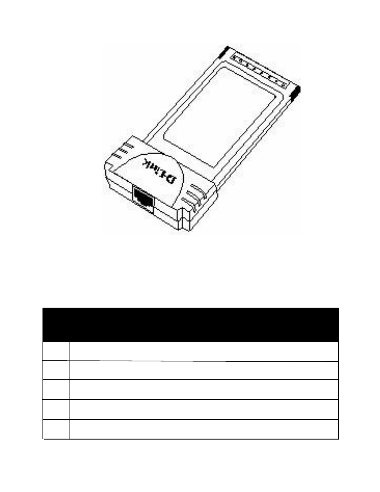
DFE-650TXD 10/100 Ethernet PC Card
Package Contents
A DFE-650TXD 10/100 Ethernet PC Card
B Driver CD
C User's Manual in CD
D Quick Install Guide
E
One plastic storage bag for the DFE-650TXD card
DFE-650TXD 10/100
Ethernet PC Card

About Fast Ethernet
Fast Ethernet is a network technology specified by IEEE Standard
802.3u. It extends the traditional 10Mbps (10 megabit/sec)
Ethernet technology to achieve 100Mbps (100 megabit/sec) trans
-
mission and reception. Because Fast Ethernet retains the tradition
-
al Ethernet CSMA/CD (Carrier Sense, Multiple Access, Collision
Detect) protocol, it remains wholly compatible with 10Mbps
Ethernet while providing a tenfold increase in network capacity.
The Fast Ethernet standard specifies three subt
ypes, correspon
-
ding to three media types:
?
100Base-TX (using two twisted pairs in EIA 568 Category 5
UTP or STP cable)
? 100Base-T4 (using four twisted pairs in a Category 3,
Category 4, or Category 5 UTP cable)
? 100Base-FX (using two fiber-optic strands.)
The DFE-650TXD provides full-duplex and half-duplex
100Base-TX operation (in Category 5 twisted-pair cable environ
-
ments). It does not provide 100Base-T4 or 100Base-FX operation.
To provide for traditional 10Mbps Ethernet operation in twisted-pair
cable environments, the DFE-650TXD also offers 10Mbps
Ethernet operation, in full-duplex and half-duplex modes. The
DFE-650TXD's autonegotiation capability provides for automatic
selection of the best operation mode.
1

About Autonegotiation
The basic idea of auto-negotiation is similar to the familiar process
of making a dialup connection between two modems. When you
attempt a connection you have probably heard some gravelly-
sounding exchanges between your local modem and a modem at
the other end of a telephone line. These annoying sounds let you
know that your modem and the remote modem are preparing for
your intended communication with the remote computer.
During those few seconds before you see the "connect" message
the modems are negotiating the best data communication scheme
which is supported by both modems, and which is suitable for the
quality of the telephone-line connection between them. The
parameters to be settled between the two modems include best
baud rate, compression method, and error correction method.
When the two modems have tested the phone-line quality and
have switched to the combination of parameters which will provide
the best data communication, then you are given the "connect"
message which signals the end of the inter-modem negotiation and
the beginning of your intended communication with the remote
computer.
Autonegotiation between devices within an Ethernet LAN is similar
in concept, but much briefer. The two devices involved in the
autonegotiation will be your DFE-650TXD and the switch or hub
through which it is connected into the LAN. (Switches ordinarily
provide for autonegotiation; traditional hubs do not.)
The parameters to be negotiated between the DFE-650TXD
and its supporting switch or hub include speed (100Mbps = Fast
Ethernet, or 10Mbps = traditional Ethernet) and duplex mode (half-
duplex or full-duplex.)
2

About Autonegotiation continued
Startup communication between the two devices occurs
when both devices are operating, the cable connection
between them is good, and the connected notebook PC's
network software is loaded. As soon as those conditions are
satisfied, the preparatory process of auto-negotiation
between the DFE-650TXD and its supporting device
begins and proceeds automatically.
If the supporting switch or hub has autonegotiation functional
-
ity, then it and the DFE-650TXD exchange a series of
messages in which each device signals its capabilities and
listens for corresponding information about the other. The
auto-negotiation process requires only a few milliseconds,
and the two devices select the best communication parame
-
ters supported by both devices.
If the supporting device does not have autonegotiation func
-
tionality, then its monotone (single capability) message will be
recognized by the DFE-650TXD's autonegotiation facility,
and the DFE-650TXD will simply switch to the one of its
own capabilities which matches that of the supporting device.
Once the auto-negotiation is completed, then the line is
ready, and it will provide an optimal data channel between the
DFE-650TXD and the supporting device. The line will
remain ready without further auto-negotiation action until the
linkage is broken. Auto-negotiation then reoccurs at any time
that the linkage is restored, again making the line ready for
optimal data communications.
3

TROUBLESHOOTING
A network can be simple to install and maintain. However,
occasionally something might go wrong. The best approach to
troubleshooting network problems is to start at the very simplest
level and work your way up.
On the following pages we have covered many of the common
troubleshooting situations. Please read through these
pages or skip to the specific one that interests you.
4

TROUBLESHOOTING continued
UNDERSTANDING THE INDICATORS
Your DFE-650TXD PC Card has indicator lights that can give you
information about your network traffic and help you determine
problems when troubleshooting.
The DFE-650TXD PC Card has six LED indicators:
1. 100/10 Indicator:
An orange light indicates that it is ON.
2. Full Indicator: A green light indicates that it is ON.
3. Link Indicator: A green light indicates that it is ON.
4. RX Indicator:
A green and flashing light indicates that
data is being received
5. TX Indicator:
A green and flashing light indicates that data
is being transmitted.
6. COL Indicator: An orange light indicates interference.
5
Full
Link
100/10
TX
COL
RX

Troubleshooting the Hardware Installation
If you experience any problems with the hardware installation, first
ascertain that all network cable connections are firm, that the prop
-
er grade of cable is used for the network connection, and that the
cable makeup is correct (straight -- without un-needed crossovers
in the connector wiring.) Check that the supporting hub is power-
on and operating normally, and that the hub is properly qualified
(under 10Base-T and/or 100Base-TX standards.)
Verify Each Computers Identification
If more than one computer on your network has the same
"Computer name," communications may be negatively affected.
Also, each computer must have the same "Workgroup" name to
communicate properly.
Verify Network Adapter Installation
If your Network Adapter were not installed, including the Network
System Software or Device drivers, your network will not function
properly. Use these steps to verify that your Network Adapter are
properly installed.
1. Double-Click the "System" icon in the Control Panel.
2. Click the "Device Manager" tab on top of the "System
Properties" dialog box.
3.
Double-Click "Network Adapters" if you do not see any
items branching out. You should see "D-Link DFE-650TX
/TXD PCMCIA PC Card branching out after double-Clicking
Network Adapters."
If you do not see any items branching out after double-clicking
"Network Adapters," your Network Adapter has not been properly
installed. Start at the beginning of the guide and follow these steps
for this computer.
TROUBLESHOOTING continued
6

TROUBLESHOOTINGcontinued
If you see symbols such as yellow exclamation point or red "X" over
the icon adjacent to "D-Link DFE-650TX/TXD PC Card," your card
is not installed properly or may have a problem. Double-click the
"D-Link DFE-650TX/TXD PC Card" read the explanation of the
problem. This information will be helpful if you require technical
support from D-Link.
Verify Cable Connections
Check to see that the computer(s) you are troubleshooting are
properly connected. Each computer must be connected from its
DFE-650TXD with a Category 5 cable. Examine the network
cables and ensure that they have not been damaged by having
been walked-on, rolled over by chairs, or closed in doors.
Additionally, make note of and alleviate any possible electromag
-
netic interference that may be affecting your network.
Your network cables can be plugged into any port on your hub
except the "Uplink" port. The "Uplink" port is only used when con
-
necting your hub to another hub or switch.
7

Diagnostics and Checking Communications
Included on the CD-ROM is a "DFE-650TXD PCMCIA Adapter
Driver Program." It is a diagnostic program that will help you deter
-
mine if any faults exist in your DFE-650TXD Network Adapters or
connection.
1.
Restart your computer in MS-DOS mode. (Click "Start,"
then ""Shut Down" and finally select ""Restart the
computer in MS-DOS mode.")
2. Insert the CD-ROM labeled "DFE-650TXD PCMCIA
Ethernet Adapter Driver Program" into your CD-ROM D:\
3. Type D:\DIAG.EXE at the MS-DOS prompt and press
"Enter" to start the D-Link PCMCIA Fast Ethernet Adapter
Diagnostic Program.
4.
Read the follow the instructions on the screen (Press F1
key anytime for additional help.)
5.
"Adapter Basic Diagnostic" will determine if any problems
exist with DFE-650TXD.
6.
"Network Diagnostic" will determine if problems exist with
your network or connections. To use "Network Diagnostic,"
please run program on both computers in MS-DOS Mode.
If you encounter any problems, please contact
D-Link technical support.
TROUBLESHOOTING continued
8
TROUBLESHOOTING continued
9
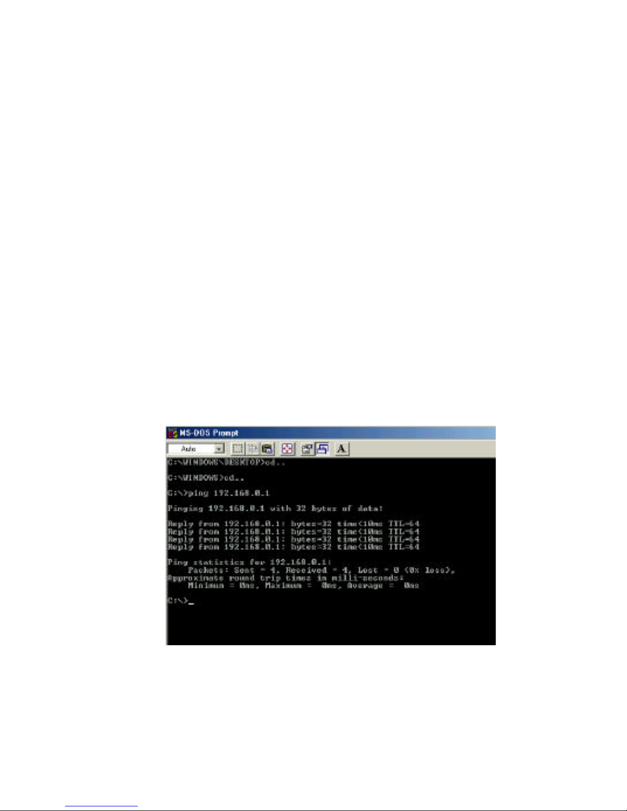
Pinging your DFE-650TXD Card
Follow these steps to Ping a device:
Ping is the acronym for Packet Internet Groper (PING), a utility to
determine if a specific IP address is accessible. It works by send
-
ing a packet to the specified address and waiting for a reply. Ping
is primarily used to troubleshoot Internet connections. By sending
out a ping, you are verifying that a specific computer is available.
Since all computers on the network must have a unique IP
address, getting a reply means that a computer is on the network
and can communicate. If you cannot ping another computer, then
there is probably a problem with the hardware. Check the cabling
and adapter installation. If you are unable to network, even when
you receive a reply to your ping, it is probably a software configu
-
ration issue. Verify that all the settings are correct.
1. Start MS-DOS Prompt.
2. Type in the following: ping:xxx.xxx.xx.xx, where
xxx.xxx.xx.xx is the IP address to be pinged (i.e.
192.168.0.1.) and hit the enter key. In this case,
computer A is pinging its own IP address.
A successful ping shows four replies.

TROUBLESHOOTING
HOW TO FREE AN IRQ
What to do if you don't have an available IRQ
If there is not an available (open) IRQs on your system, you can do
the following:
The first thing you can do is let your Motherboard and Windows do
the work for you. For this option you will need to check that you
have a Plug and Play compatible Motherboard and set it to reset
the configuration.
Note:
All of the setting names below may not be the exact wording
on your system. This is due to the great number of Motherboard
and hardware manufacturers. The settings may be listed on your
system using different words that mean the same thing. Refer to
your motherboards's manual or contact the manufacturer if you are
unsure.
Perform the following steps to check for a Plug and Play
Motherboard and to reset the configuration.
1. Reboot your computer.
2. When your computer is going through its POST
(Power On Self Test) enter into your BIOS(Basic
Input/Output System).
3. Some BIOS's have a setting that will let you
enable the Motherboard for Plug and Play. You
should look for a setting that says "Plug and
Play OS." "Enable" this function.
4. The second setting to look for is under the
heading "PNP/PCI Configuration." Under
this heading check to make sure that "Resources
Controlled By" is set to "Auto."
10

5. The next setting below should be "Reset
Configuration" or "Reset ESSCD." Set this to a
"Enabled."
Note: This is a one-time setting. Meaning after
you reboot your computer the setting will return to
"Disabled." This setting allows Windows to recon-
figure all of the configuration information for your
Plug and Play hardware. It is reset to "Disabled" so
that Windows will not perform the reconfiguration
each time you start your computer.
6. "Save" the new settings and Exit your BIOS. This
will allow your computer to boot up and load Windows.
7. After Windows loads, check in the Device Manager to
see if there is an available IRQ.
TROUBLESHOOTING
HOW TO FREE AN IRQ
What to do if you don't have an available IRQ
continued
11

TROUBLESHOOTING
HOW TO FREE AN IRQ
If you do not have a Plug and Play Motherboard or you still do
not have a free IRQ
If you do not have a Plug and Play Motherboard or you still do not
have a free IRQ you might need to disable some unused
Hardware. For instance if you have a PS/2 or USB Mouse then
you might be able to disable your COM Ports.
Perform the following steps to disable your COM Ports.
1. Reboot your computer.
2. When your computer is going through its POST
(Power On Self Test) enter into your BIOS (Basic
Input/Output System).
3. Under the heading "Integrated Peripherals," look for
"Serial Port 1 or 2" or "COM Port 1 or 2."
4. Change the setting to "Disable."
5. Go to the heading "PNP/PCI Configuration."
6. Make sure the setting for "Resources Controlled
By" is set to "Auto."
7. Change the setting for "Reset Configuration" to
"Enabled."
8. Hit the "ESC" key and go to the heading "Save and
Exit."
9. Let Windows load and follow the steps to Checking
for an Available IRQ.
12

TROUBLESHOOTING
HOW TO FREE AN IRQ
If you do not have a Plug and Play Motherboard or you still do
not have a free IRQ
continued
Other hardware that can be disabled
are referred to as "Built On." If your Motherboard has a "Built On"
if it is disabled.
Perform the following steps to disable a "Built On "
Modem.
1. Reboot your computer.
2. When your computer is going through its POST
(Power On Self Test) enter into your BIOS (Basic
Input/Output System).
3. Under the heading "Integrated Peripherals,"
look for
a setting "Modem COM Port. "
4. Change the setting to "Disable."
Note: Only disable your "Built On "
Modem if you
know that you have upgraded your Modem, you
have had a Broadband connection (Cable/DSL)
installed, or if you do not use it to connect to the
Internet. Disabling the "Built On "
Modem will make
it so it no longer functions, until reset to "
enabled.
"
5. Go to the heading "PNP/PCI Configuration."
6. Make sure the setting for "
Resources Controlled
By" is set to "Auto."
13
 Loading...