

Page 1
DES-3250G
Layer 2 Switch
Command Line Interface
Reference Manual
First Edition (February 2003)
DES3250TG.A1
Printed In Taiwan
RECYCLABLE
Page 2

Wichtige Sicherheitshinweise
1. Bitte lesen Sie sich diese Hinweise sorgfältig durch.
2. Heben Sie diese Anleitung für den spätern Gebrauch auf.
3. Vor jedem Reinigen ist das Gerät vom Stromnetz zu trennen. Vervenden Sie keine
Flüssig- oder Aerosolreiniger. Am besten dient ein angefeuchtetes Tuch zur
Reinigung.
4. Um eine Beschädigung des Gerätes zu vermeiden sollten Sie nur Zubehörteile
verwenden, die vom Hersteller zugelassen sind.
5. Das Gerät is vor Feuchtigkeit zu schützen.
6. Bei der Aufstellung des Gerätes ist auf sichern Stand zu achten. Ein Kippen oder
Fallen könnte Verletzungen hervorrufen. Verwenden Sie nur sichere Standorte und
beachten Sie die Aufstellhinweise des Herstellers.
7. Die Belüftungsöffnungen dienen zur Luftzirkulation die das Gerät vor Überhitzung
schützt. Sorgen Sie dafür, daß diese Öffnungen nicht abgedeckt werden.
8. Beachten Sie beim Anschluß an das Stromnetz die Anschlußwerte.
9. Die Netzanschlußsteckdose muß aus Gründen der elektrischen Sicherheit einen
Schutzleiterkontakt haben.
10. Verlegen Sie die Netzanschlußleitung so, daß niemand darüber fallen kann. Es sollete
auch nichts auf der Leitung abgestellt werden.
11. Alle Hinweise und Warnungen die sich am Geräten befinden sind zu beachten.
12. Wird das Gerät über einen längeren Zeitraum nicht benutzt, sollten Sie es vom
Stromnetz trennen. Somit wird im Falle einer Überspannung eine Beschädigung
vermieden.
13. Durch die Lüftungsöffnungen dürfen niemals Gegenstände oder Flüssigkeiten in das
Gerät gelangen. Dies könnte einen Brand bzw. Elektrischen Schlag auslösen.
14. Öffnen Sie niemals das Gerät. Das Gerät darf aus Gründen der elektrischen
Sicherheit nur von authorisiertem Servicepersonal geöffnet werden.
15. Wenn folgende Situationen auftreten ist das Gerät vom Stromnetz zu trennen und von
einer qualifizierten Servicestelle zu überprüfen:
a – Netzkabel oder Netzstecker sint beschädigt.
b – Flüssigkeit ist in das Gerät eingedrungen.
c – Das Gerät war Feuchtigkeit ausgesetzt.
d – Wenn das Gerät nicht der Bedienungsanleitung ensprechend funktioniert oder Sie
mit Hilfe dieser Anleitung keine Verbesserung erzielen.
e – Das Gerät ist gefallen und/oder das Gehäuse ist beschädigt.
f – Wenn das Gerät deutliche Anzeichen eines Defektes aufweist.
16. Bei Reparaturen dürfen nur Orginalersatzteile bzw. den Orginalteilen entsprechende
Teile verwendet werden. Der Einsatz von ungeeigneten Ersatzteilen kann eine weitere
Beschädigung hervorrufen.
17. Wenden Sie sich mit allen Fragen die Service und Repartur betreffen an Ihren
Servicepartner. Somit stellen Sie die Betriebssicherheit des Gerätes sicher.
Page 3

18. Zum Netzanschluß dieses Gerätes ist eine geprüfte Leitung zu verwenden, Für einen
Nennstrom bis 6A und einem Gerätegewicht grőßer 3kg ist eine Leitung nicht leichter
als H05VV-F, 3G, 0.75mm2 einzusetzen.
Page 4

WARRANTIES EXCLUSIVE
IF THE D-LINK PRODUCT DOES NOT OPERATE AS WARRANTED ABOVE, THE
CUSTOMER'S SOLE REMEDY SHALL BE, AT D-LINK'S OPTION, REPAIR OR
REPLACEMENT. THE FOREGOING WARRANTIES AND REMEDIES ARE EXCLUSIVE AND
ARE IN LIEU OF ALL OTHER WARRANTIES, EXPRESSED OR IMPLIED, EITHER IN FACT
OR BY OPERATION OF LAW, STATUTORY OR OTHERWISE, INCLUDING WARRANTIES
OF MERCHANTABILITY AND FITNESS FOR A PARTICULAR PURPOSE. D-LINK NEITHER
ASSUMES NOR AUTHORIZES ANY OTHER PERSON TO ASSUME FOR IT ANY OTHER
LIABILITY IN CONNECTION WITH THE SALE, INSTALLATION MAINTENANCE OR USE OF
D-LINK'S PRODUCTS
D-LINK SHALL NOT BE LIABLE UNDER THIS WARRANTY IF ITS TESTING AND
EXAMINATION DISCLOSE THAT THE ALLEGED DEFECT IN THE PRODUCT DOES NOT
EXIST OR WAS CAUSED BY THE CUSTOMER'S OR ANY THIRD PERSON'S MISUSE,
NEGLECT, IMPROPER INSTALLATION OR TESTING, UNAUTHORIZED ATTEMPTS TO
REPAIR, OR ANY OTHER CAUSE BEYOND THE RANGE OF THE INTENDED USE, OR BY
ACCIDENT, FIRE, LIGHTNING OR OTHER HAZARD.
LIMITATION OF LIABILITY
IN NO EVENT WILL D-LINK BE LIABLE FOR ANY DAMAGES, INCLUDING LOSS OF
DATA, LOSS OF PROFITS, COST OF COVER OR OTHER INCIDENTAL, CONSEQUENTIAL
OR INDIRECT DAMAGES ARISING OUT THE INSTALLATION, MAINTENANCE, USE,
PERFORMANCE, FAILURE OR INTERRUPTION OF A D- LINK PRODUCT, HOWEVER
CAUSED AND ON ANY THEORY OF LIABILITY. THIS LIMITATION WILL APPLY EVEN IF
D-LINK HAS BEEN ADVISED OF THE POSSIBILITY OF SUCH DAMAGE.
IF YOU PURCHASED A D-LINK PRODUCT IN THE UNITED STATES, SOME STATES DO
NOT ALLOW THE LIMITATION OR EXCLUSION OF LIABILITY FOR INCIDENTAL OR
CONSEQUENTIAL DAMAGES, SO THE ABOVE LIMITATION MAY NOT APPLY TO YOU.
Limited Warranty
Hardware:
D-Link warrants each of its hardware products to be free from defects in workmanship
and materials under normal use and service for a period commencing on the date of
purchase from D-Link or its Authorized Reseller and extending for the length of time
stipulated by the Authorized Reseller or D-Link Branch Office nearest to the place of
purchase.
This Warranty applies on the condition that the product Registration Card is filled out and
returned to a D-Link office within ninety (90) days of purchase. A list of D-Link offices is
provided at the back of this manual, together with a copy of the Registration Card.
If the product proves defective within the applicable warranty period, D-Link will provide
repair or replacement of the product. D-Link shall have the sole discretion whether to
repair or replace, and replacement product may be new or reconditioned. Replacement
product shall be of equivalent or better specifications, relative to the defective product, but
need not be identical. Any product or part repaired by D-Link pursuant to this warranty
shall have a warranty period of not less than 90 days, from date of such repair,
Page 5

irrespective of any earlier expiration of original warranty period. When D-Link provides
replacement, then the defective product becomes the property of D-Link.
Warranty service may be obtained by contacting a D-Link office within the applicable
warranty period, and requesting a Return Material Authorization (RMA) number. If a
Registration Card for the product in question has not been returned to D-Link, then a
proof of purchase (such as a copy of the dated purchase invoice) must be provided. If
Purchaser's circumstances require special handling of warranty correction, then at the
time of requesting RMA number, Purchaser may also propose special procedure as may be
suitable to the case.
After an RMA number is issued, the defective product must be packaged securely in the
original or other suitable shipping package to ensure that it will not be damaged in
transit, and the RMA number must be prominently marked on the outside of the package.
The package must be mailed or otherwise shipped to D-Link with all costs of
mailing/shipping/insurance prepaid. D-Link shall never be responsible for any software,
firmware, information, or memory data of Purchaser contained in, stored on, or integrated
with any product returned to D-Link pursuant to this warranty.
Any package returned to D-Link without an RMA number will be rejected and shipped
back to Purchaser at Purchaser's expense, and D-Link reserves the right in such a case to
levy a reasonable handling charge in addition mailing or shipping costs.
Software:
Warranty service for software products may be obtained by contacting a D-Link office
within the applicable warranty period. A list of D-Link offices is provided at the back of
this manual, together with a copy of the Registration Card. If a Registration Card for the
product in question has not been returned to a D-Link office, then a proof of purchase
(such as a copy of the dated purchase invoice) must be provided when requesting
warranty service. The term "purchase" in this software warranty refers to the purchase
transaction and resulting license to use such software.
D-Link warrants that its software products will perform in substantial conformance with
the applicable product documentation provided by D-Link with such software product, for
a period of ninety (90) days from the date of purchase from D-Link or its Authorized
Reseller. D-Link warrants the magnetic media, on which D-Link provides its software
product, against failure during the same warranty period. This warranty applies to
purchased software, and to replacement software provided by D-Link pursuant to this
warranty, but shall not apply to any update or replacement which may be provided for
download via the Internet, or to any update which may otherwise be provided free of
charge.
D-Link's sole obligation under this software warranty shall be to replace any defective
software product with product which substantially conforms to D-Link's applicable
product documentation. Purchaser assumes responsibility for the selection of appropriate
application and system/platform software and associated reference materials. D-Link
makes no warranty that its software products will work in combination with any
hardware, or any application or system/platform software product provided by any third
party, excepting only such products as are expressly represented, in D-Link's applicable
product documentation as being compatible. D-Link's obligation under this warranty
shall be a reasonable effort to provide compatibility, but D-Link shall have no obligation to
provide compatibility when there is fault in the third-party hardware or software. D-Link
makes no warranty that operation of its software products will be uninterrupted or
Page 6

absolutely error-free, and no warranty that all defects in the software product, within or
without the scope of D-Link's applicable product documentation, will be corrected.
Page 7

D-Link Offices for Registration and Warranty Service
The product's Registration Card, provided at the back of this manual, must be sent to a
D-Link office. To obtain an RMA number for warranty service as to a hardware product,
or to obtain warranty service as to a software product, contact the D-Link office nearest
you. An address/telephone/fax/e-mail/Web site list of D-Link offices is provided in the
back of this manual.
Trademarks
Copyright 2003 D-Link Corporation.
Contents subject to change without prior notice.
D-Link is a registered trademark of D-Link Corporation/D-Link
Systems, Inc. All other trademarks belong to their respective
proprietors.
Copyright Statement
No part of this publication may be reproduced in any form or by any
means or used to make any derivative such as translation,
transformation, or adaptation without permission from D-Link
Corporation/D-Link Systems Inc., as stipulated by the United States
Copyright Act of 1976.
Page 8
FCC Warning
This equipment has been tested and found to comply with the limits
for a Class A digital device, pursuant to Part 15 of the FCC Rules.
These limits are designed to provide reasonable protection against
harmful interference when the equipment is operated in a commercial
environment. This equipment generates, uses, and can radiate radio
frequency energy and, if not installed and used in accordance with
this user’s guide, may cause harmful interference to radio
communications. Operation of this equipment in a residential area is
likely to cause harmful interference in which case the user will be
required to correct the interference at his own expense.
CE Mark Warning
This is a Class A product. In a domestic environment, this product
may cause radio interference in which case the user may be required
to take adequate measures.
VCCI Warning
BSMI Warning
Page 9

Table of Contents
Introduction ........................................................................ 11
Using the Console CLI ......................................................... 16
Command Syntax................................................................ 24
Basic Switch Commands..................................................... 29
Switch Port Commands ....................................................... 49
Network Management Commands ....................................... 53
Download/Upload Commands ............................................ 76
Network Monitoring Commands .......................................... 80
Spanning Tree Commands .................................................. 88
Layer 2 Forwarding Database Commands ........................... 96
Broadcast Storm Control Commands ................................ 111
QOS Commands ............................................................... 115
Port Mirroring Commands................................................. 134
VLAN Commands .............................................................. 141
Link Aggregation Commands............................................. 155
IP Interface Commands ..................................................... 163
IGMP Snooping Commands............................................... 167
ix
Page 10

Routing Table Commands ................................................. 181
Command History List ...................................................... 185
Technical Specifications .................................................... 191
Switch System Messages ................................................... 194
x
Page 11

DES-3250TG Layer 2 Fast Ethernet Switch User’s Guide
1
INTRODUCTION
The switch can be managed through the switch’s serial port,
Telnet, or the Web-based management agent. The Command
Line Interface (CLI) can be used to configure and manage the
switch via the serial port or Telnet interfaces.
This manual provides a reference for all of the commands
contained in the CLI. Configuration and management of the
switch via the Web-based management agent is discussed in the
User’s Guide.
Accessing the Switch via the Serial Port
The switch’s serial port’s default settings are as follows:
• 9600 baud
• no parity
• 8 data bits
• 1 stop bit
A computer running a terminal emulation program capable of
emulating a VT-100/ANSI terminal and a serial port configured
as above is then connected to the switch’s serial port via an RS232 DB-9 cable.
11
Page 12

DES-3250TG Layer 2 Fast Ethernet Switch User’s Guide
With the serial port properly connected to a management
computer, the following screen should be visible. If this screen
does not appear, try pressing Ctrl+R to refresh the console
screen.
Figure 1-1. Initial Console screen.
There is no initial username or password. Just press the Enter
key twice to display the CLI input cursor − local>. This is the
command line where all commands are input.
Setting the Switch’s IP Address
Each Switch must be assigned its own IP Address, which is
used for communication with an SNMP network manager or
other TCP/IP application (for example BOOTP, TFTP). The
switch’s default IP address is 10.90.90.90. You can change the
default Switch IP address to meet the specification of your
networking address scheme.
12
Page 13
DES-3250TG Layer 2 Fast Ethernet Switch User’s Guide
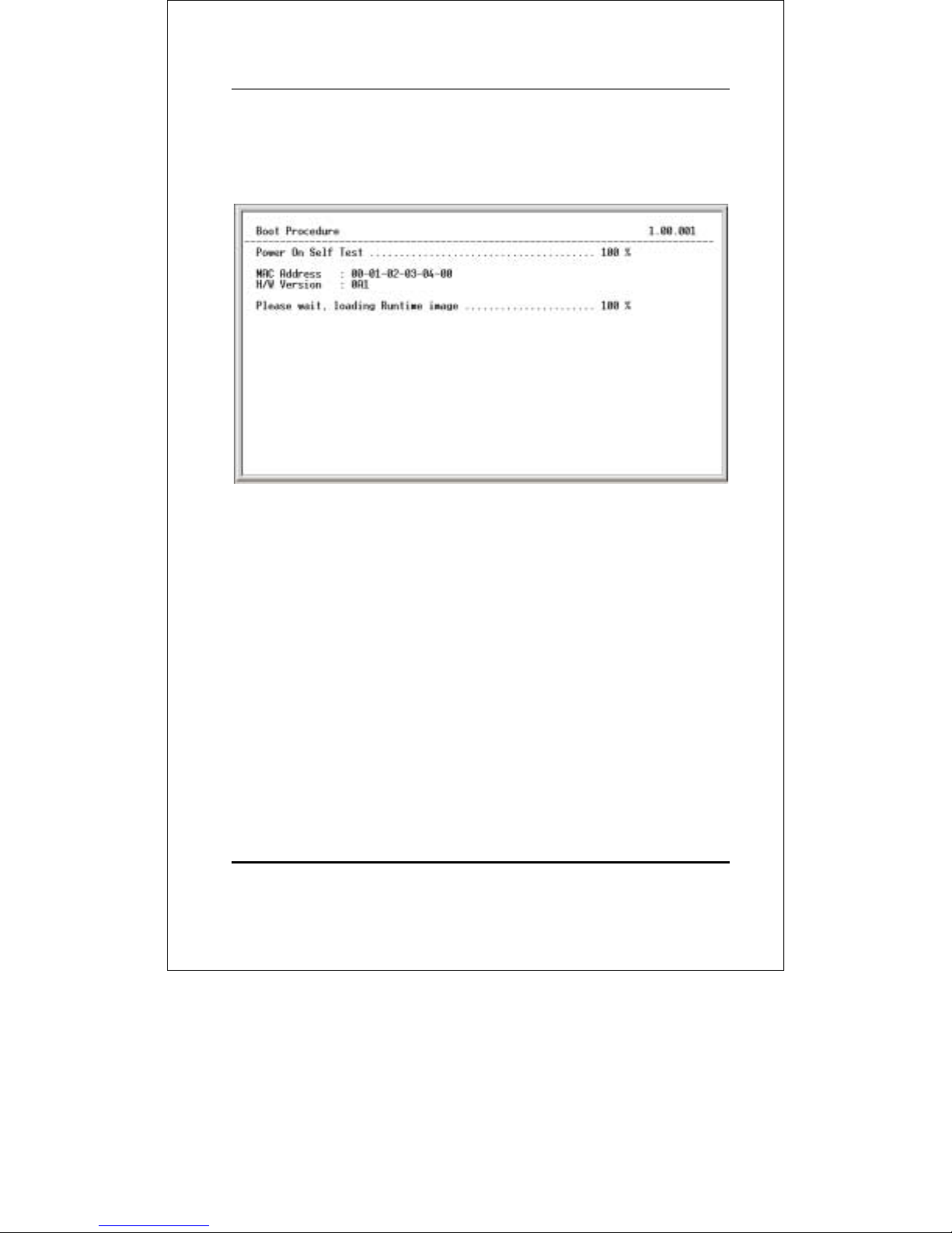
The switch is also assigned a unique MAC address by the
factory. This MAC address cannot be changed, and can be found
from the initial boot console screen – shown below.
Figure 1-2. Boot Screen
The switch’s MAC address can also be found from the Web
management program on the Switch Information (Basic
Settings) window on the Configuration menu.
The IP address for the switch must be set before it can be
managed with the Web-based manager. The switch IP address
can be automatically set using BOOTP or DHCP protocols, in
which case the actual address assigned to the switch must be
known.
The IP address may be set using the Command Line Interface
(CLI) over the console serial port as follows:
1. Starting at the command line prompt, enter the
commands config ipif System ipaddress
xxx.xxx.xxx.xxx/yyy.yyy.yyy.yyy. Where the x’s
13
Page 14
DES-3250TG Layer 2 Fast Ethernet Switch User’s Guide
represent the IP address to be assigned to the IP
interface named System and the y’s represent the
corresponding subnet mask.
2. Alternatively, you can enter config ipif System
ipaddress xxx.xxx.xxx.xxx/z. Where the x’s
represent the IP address to be assigned to the IP
interface named System and the z represents the
corresponding number of subnets in CIDR notation.
The IP interface named System on the switch can be assigned
an IP address and subnet mask which can then be used to
connect a management station to the switch’s Telnet or Webbased management agent.
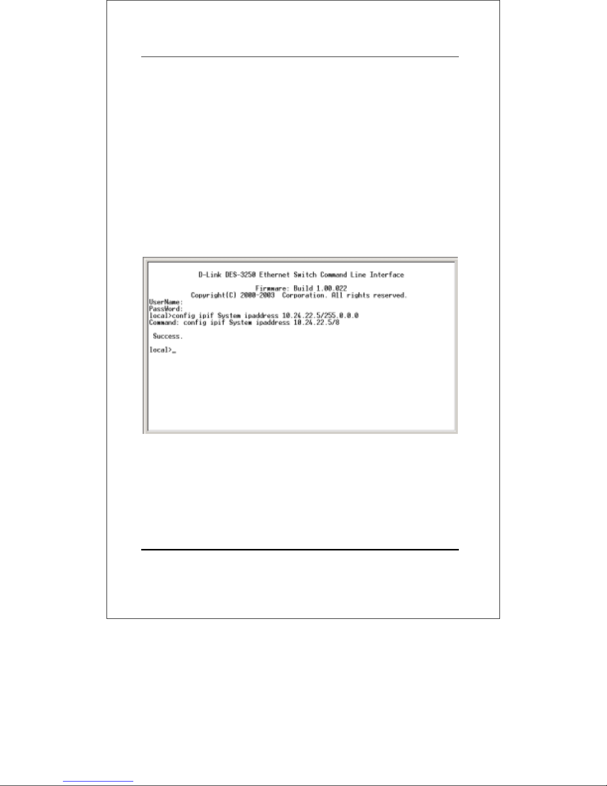
Figure 1-3. Assigning the Switch an IP Address
In the above example, the switch was assigned an IP address of
10.24.22.5 with a subnet mask of 255.0.0.0. The system
message Success indicates that the command was executed
successfully. The switch can now be configured and managed
14
Page 15

DES-3250TG Layer 2 Fast Ethernet Switch User’s Guide
via Telnet and the CLI or via the Web-based management agent
using the above IP address to connect to the switch.
15
Page 16
DES-3250TG Layer 2 Fast Ethernet Switch User’s Guide
2
USING THE CONSOLE
CLI
The DES-3250TG supports a console management interface that
allows the user to connect to the switch’s management agent via
a serial port and a terminal or a computer running a terminal
emulation program. The console can also be used over the
network using the TCP/IP Telnet protocol. The console program
can be used to configure the switch to use an SNMP-based
network management software over the network.
This chapter describes how to use the console interface to
access the switch, change its settings, and monitor its
operation.
Switch configuration settings are saved to nonvolatile RAM using save command. The current
configuration will then be retained in the switch’s
NV-RAM, and reloaded when the switch is
rebooted. If the switch is rebooted without using
the save command, the last configuration saved
to NV-RAM will be loaded.
Connecting to the Switch
The console interface is used by connecting the Switch to a
VT100-compatible terminal or a computer running an ordinary
16
Page 17

DES-3250TG Layer 2 Fast Ethernet Switch User’s Guide
terminal emulator program (e.g., the HyperTerminal program
included with the Windows operating system) using an RS-232C
serial cable. Your terminal parameters will need to be set to:
• VT-100/ANSI compatible
• 9,600 baud
• 8 data bits
• No parity
• One stop bit
• No flow control
You can also access the same functions over a Telnet interface.
Once you have set an IP address for your Switch, you can use a
Telnet program (in VT-100 compatible terminal mode) to access
and control the Switch. All of the screens are identical, whether
accessed from the console port or from a Telnet interface.
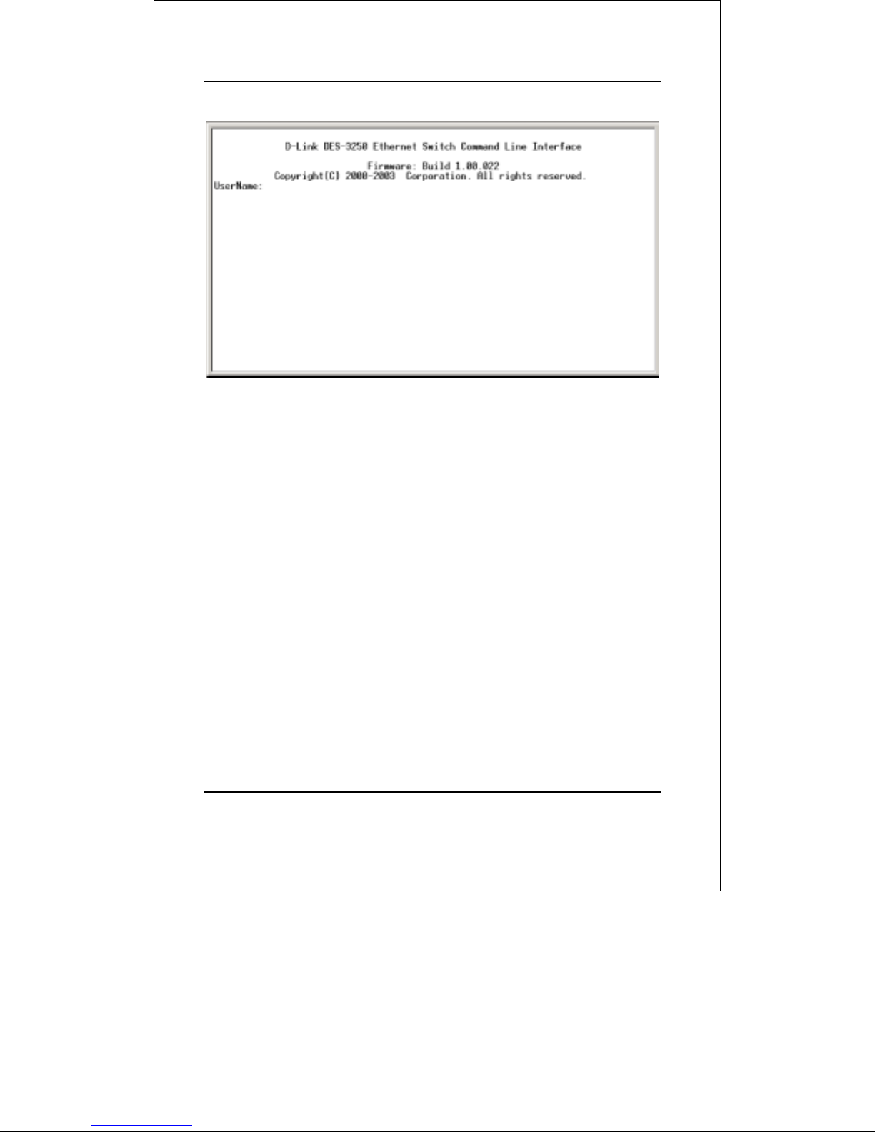
After the switch reboots and you have logged in, the console
looks like this:
17
Page 18
DES-3250TG Layer 2 Fast Ethernet Switch User’s Guide
Figure 2-1. Initial Console Screen
Commands are entered at the command prompt, local>.
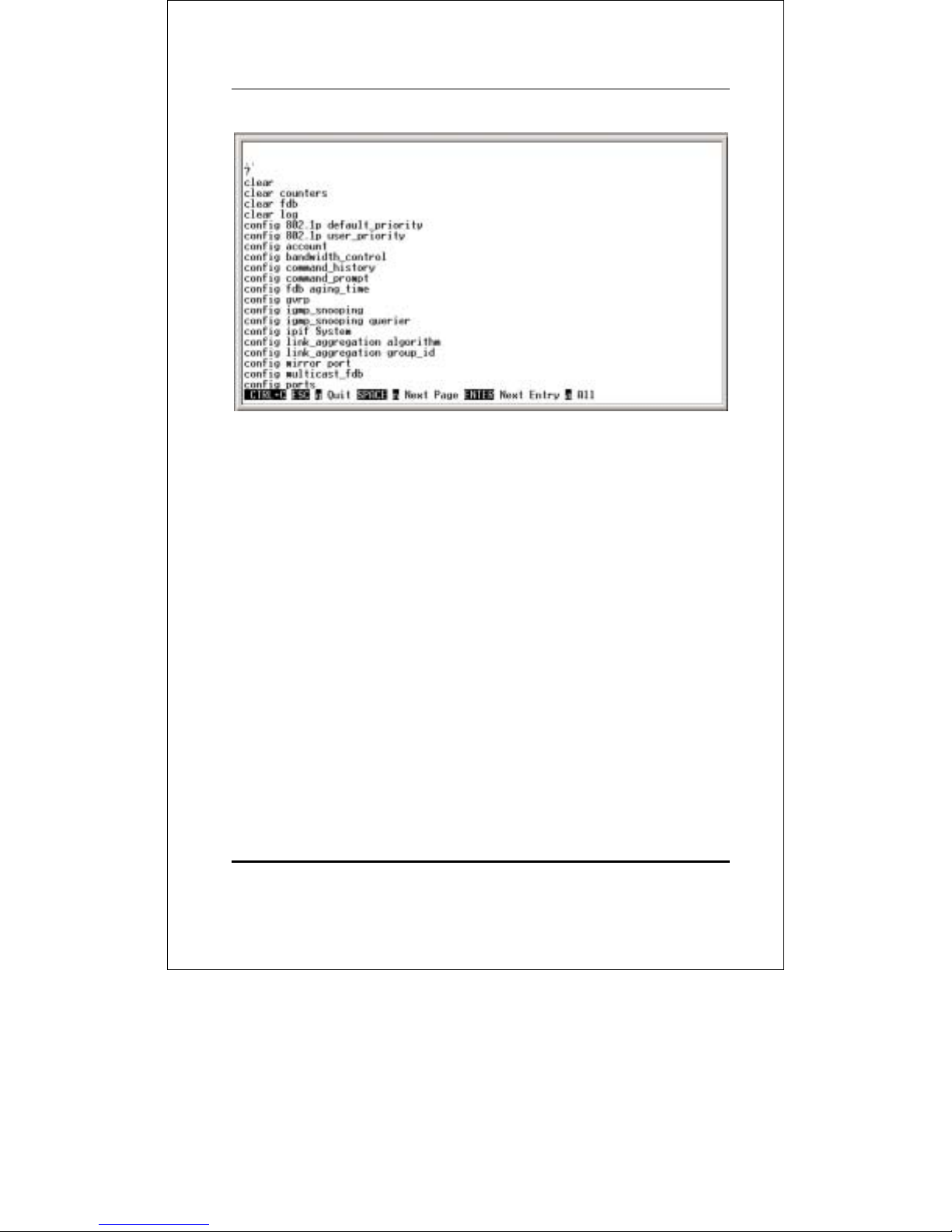
There are a number of helpful features included in the CLI.
Entering the ? command will display a list of all of the top-level
commands.
18
Page 19
DES-3250TG Layer 2 Fast Ethernet Switch User’s Guide
Figure 2-2. The ? Command
The dir command has the same function as the ? command.
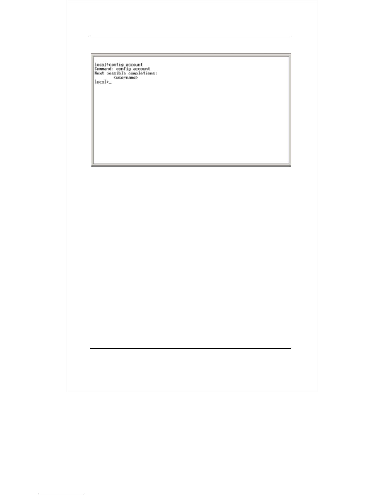
When you enter a command without its required parameters,
the CLI will prompt you with a Next possible completions:
message.
Alternatively, if you hit the Tab key immediately after you have
entered a command, the CLI will display all the next available
parameters sequentially.
19
Page 20
DES-3250TG Layer 2 Fast Ethernet Switch User’s Guide
Figure 2-3. Example Command Parameter Help
In this case, the command config account was entered with the
parameter <username>. The CLI will then prompt you to enter
the <username> with the message, Next possible
completions:. Every command in the CLI has this feature, and
complex commands have several layers of parameter prompting.
To re-enter the previous command at the command prompt,
press the up arrow cursor key. The previous command will
appear at the command prompt.
20
Page 21
DES-3250TG Layer 2 Fast Ethernet Switch User’s Guide
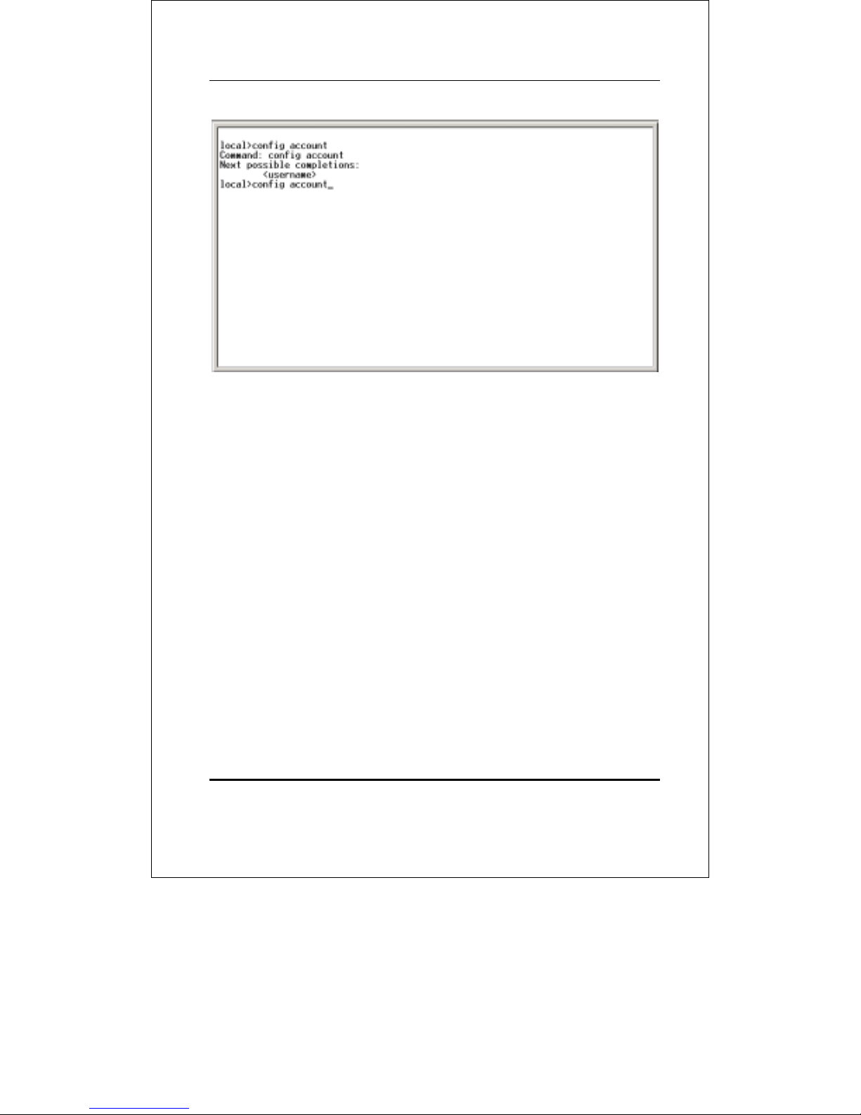
Figure 2-4. Using the Up Arrow to Re-enter a Command
In the above example, the command config account was
entered without the required parameter <username>, the CLI
returned the Next possible completions: <username> prompt.
The up arrow cursor control key was pressed to re-enter the
previous command (config account) at the command prompt.
Now the appropriate User name can be entered and the config
account command re-executed.
All commands in the CLI function in this way. In addition, the
syntax of the help prompts are the same as presented in this
manual − angle brackets < > indicate a numerical value or
character string, braces { } indicate optional parameters or a
choice of parameters, and brackets [ ] indicate required
parameters.
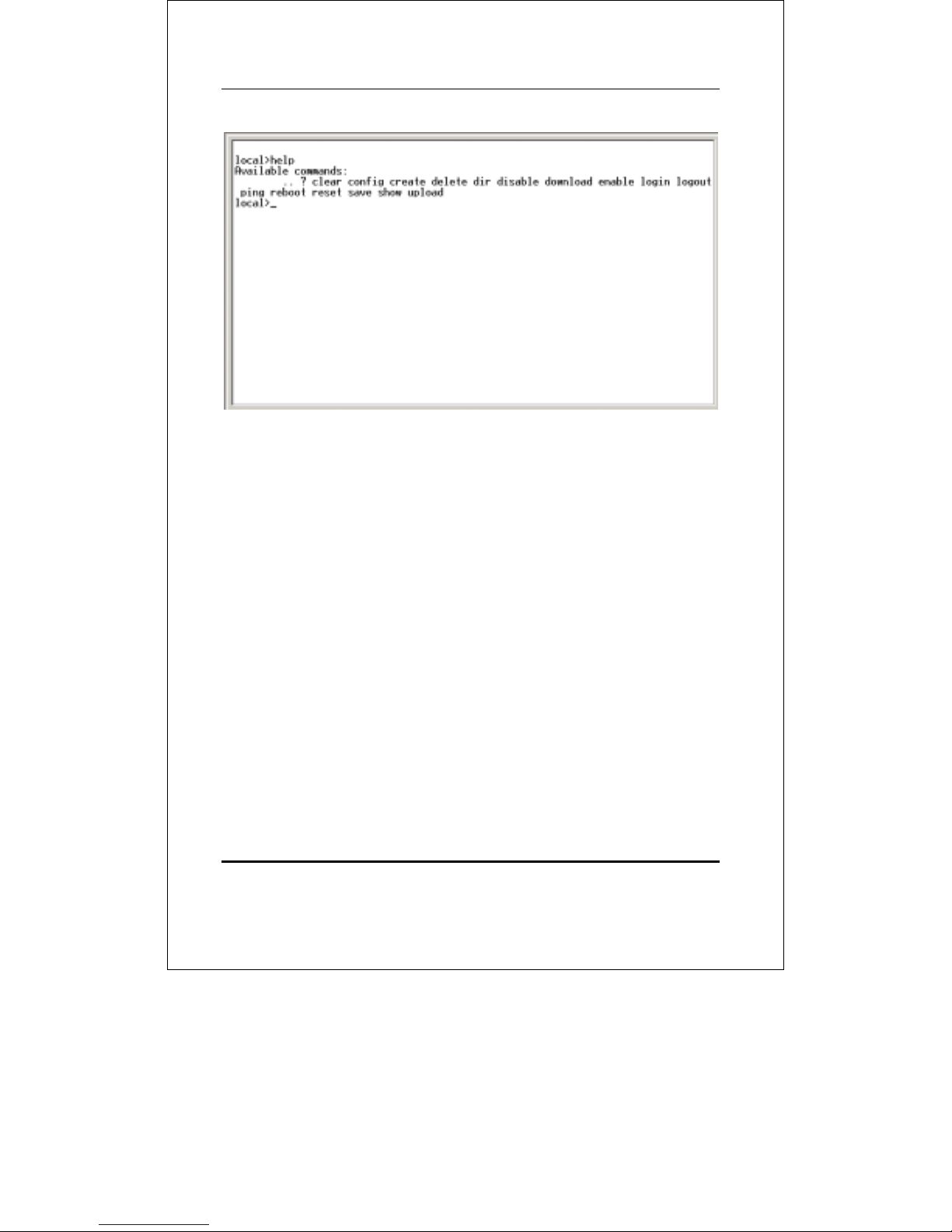
If a command is entered that is unrecognized by the CLI, the
top-level commands will be displayed under the Available
commands: prompt.
21
Page 22
DES-3250TG Layer 2 Fast Ethernet Switch User’s Guide
Figure 2-5. The Available Commands Prompt
The top-level commands consist of commands like show or
config. Most of these commands require one or more
parameters to narrow the top-level command. This is equivalent
to show what? or config what? Where the what? is the next
parameter.
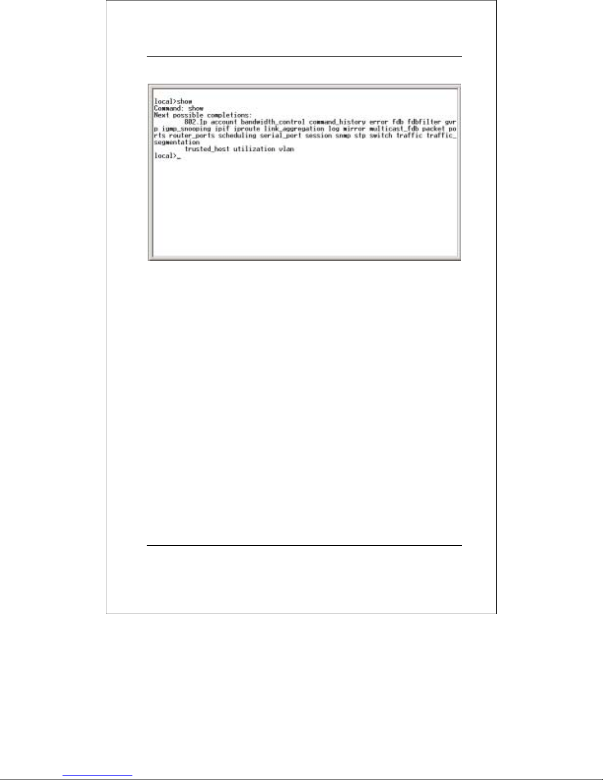
For example, if you enter the show command with no additional
parameters, the CLI will then display all of the possible next
parameters.
22
Page 23
DES-3250TG Layer 2 Fast Ethernet Switch User’s Guide
Figure 2-6. Next possible completions: Show Command
In the above example, all of the possible next parameters for the
show command are displayed. At the next command prompt,
the up arrow was used to re-enter the show command, followed
by the account parameter. The CLI then displays the user
accounts configured on the switch.
23
Page 24
DES-3250TG Layer 2 Fast Ethernet Switch User’s Guide
3
COMMAND SYNTAX
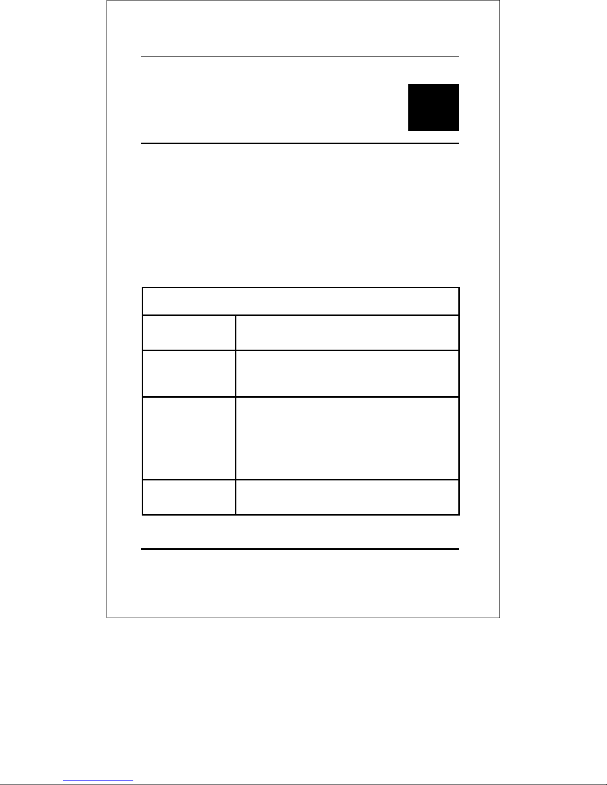
The following symbols are used to describe how command
entries are made and values and arguments are specified in this
manual. The online help contained in the CLI and available
through the console interface uses the same syntax.
<angle brackets>
Purpose Encloses a variable or value that must be
specified.
Syntax
Description In the above syntax example, you must
Example
Command
create ipif <ipif_name> vlan
<vlan_name> ipaddress
<network_address>
supply an IP interface name in the
<ipif_name> space, a VLAN name in the
<vlan_name> space, and the network
address in the <network_address> space.
Do not type the angle brackets.
create ipif Engineering vlan Design
ipaddress 10.24.22.5/255.0.0.0
24
Page 25
DES-3250TG Layer 2 Fast Ethernet Switch User’s Guide
[square brackets]
Purpose Encloses a required value or set of required
arguments. One or more values or
arguments can be specified.
Syntax
Description In the above syntax example, you must
Example
Command
create account [admin/user]
specify either an admin or a user level
account to be created. Do not type the
square brackets.
create account admin
/slash
Purpose Separates two or more mutually exclusive
items in a list − one of which must be
entered.
Syntax
Description In the above syntax example, you must
show snmp [community/trap receiver]
specify either community, trap receiver, or
detail. Do not type the backslash.
Example
Command
show snmp community
25
Page 26
DES-3250TG Layer 2 Fast Ethernet Switch User’s Guide
{braces}
Purpose Encloses an optional value or set of
optional arguments.
Syntax
Description In the above syntax example, you must
Example
command
config igmp [<ipif_name>/all] {version
<value>/query_interval
<sec>/max_response_time <sec>/
robustness_variable
<value>/last_member_query_interval
<value>/state [enabled/disabled]}
choose to enter an IP interface name in the
<ipif_name> space or all, but version
<value>, query_interval <sec>,
max_response_time <sec>,
robustness_variable <value>,
last_member_query_interval <value>, and
state [enabled/disabled] are all optional
arguments. You can specify any or all of
the arguments contained by braces. Do not
type the braces.
config igmp all version 2
Line Editing Key Usage
Delete
Deletes character under the cursor and
then shifts the remaining characters in the
line to the left.
26
Page 27
DES-3250TG Layer 2 Fast Ethernet Switch User’s Guide
Line Editing Key Usage
Backspace
Insert
Left Arrow
Right Arrow
Tab
Deletes the character to the left of the
cursor and shifts the remaining characters
in the line to the left.
Can be toggled on or off. When toggled on,
inserts text at the current cursor position
and shifts the remainder of the line to the
left.
Moves the cursor to the left.
Moves the cursor to the right.
Shifts the cursor to the next field to the
left.
Multiple Page Display Control Keys
Space
CTRL+c
ESC
Displays the next page.
Stops the display of remaining pages when
multiple pages are to be displayed.
Stops the display of remaining pages when
multiple pages are to be displayed.
n
p
q
r
Displays the next page.
Displays the previous page.
Stops the display of remaining pages when
multiple pages are to be displayed.
Refreshes the pages currently displaying.
27
Page 28

DES-3250TG Layer 2 Fast Ethernet Switch User’s Guide
Line Editing Key Usage
a
Enter
Displays the remaining pages without
pausing between pages.
Displays the next line or table entry.
28
Page 29
DES-3250TG Layer 2 Fast Ethernet Switch User’s Guide
4
BASIC SWITCH
COMMANDS
The basic switch commands in the Command Line Interface
(CLI) are listed (along with the appropriate parameters) in the
following table.
Command Parameters
create account [admin/user]
<username>
config account <username>
show account
delete account
show session
show switch
show serial_port
config serial_port baud_rate [9600/19200/38400/115200]
auto_logout [never/2_minutes/5_minutes
/10_minutes/15_minutes]
enable clipaging
disable clipaging
enable telnet <tcp_port_number>
disable telnet
enable web <tcp_port_number>
29
Page 30
DES-3250TG Layer 2 Fast Ethernet Switch User’s Guide
Command Parameters
disable web
save
reboot
reset {config/system}
login
logout
Each command is listed, in detail, in the following sections.
create account
Purpose Used to create user accounts
Syntax
Description The create account command is used to
Parameters Admin <username>
Restrictions Only Administrator-level users can issue
create [admin/user] <username>
create user accounts that consist of a
username of 1 to 15 characters and a
password of 0 to 15 characters. Up to 8
user accounts can be created.
User <username>
this command.
Usernames can be between 1 and 15
characters.
Passwords can be between 0 and 15
30
Page 31

DES-3250TG Layer 2 Fast Ethernet Switch User’s Guide
create account
characters.
Example Usage:
To create an administrator-level user account with the
username “dlink”.
local>create account admin dlink
Command: create account admin dlink
Enter a case-sensitive new password:****
Enter the new password again for confirmation:****
Success.
local>
config account
Purpose Used to configure user accounts
Syntax
Description The config account command configures a
Parameters <username>
Restrictions Only Administrator-level users can issue
config account <username>
user account that has been created using
the create account command.
this command.
31
Page 32
config account
Example Usage:
To configure the user password of “dlink” account:
local>config account dlink
Command: config account dlink
Enter a old password:****
Enter a case-sensitive new password:****
Enter the new password again for confirmation:****
Success.
local>
DES-3250TG Layer 2 Fast Ethernet Switch User’s Guide
Usernames can be between 1 and 15
characters.
Passwords can be between 0 15
characters.
show account
Purpose Used to display user accounts
Syntax
Description Displays all user accounts created on the
Parameters none.
show account
switch. Up to 8 user accounts can exist on
the switch at one time.
32
Page 33
DES-3250TG Layer 2 Fast Ethernet Switch User’s Guide
show account
Restrictions none.
Example Usage:
To display the accounts which have been created:
local>show account
Command: show account
Current Accounts:
Username Access Level
--------------- ----------- dlink Admin
local>
delete account
Purpose Used to delete an existing user account
Syntax
Description The delete account command deletes a
Parameters <username>
Restrictions Only Administrator-level users can issue
Example Usage:
To delete the user account “System”:
delete account <username>
user account that has been created using
the create account command.
this command.
33
Page 34
DES-3250TG Layer 2 Fast Ethernet Switch User’s Guide
local>delete account System
Command: delete account System
Success.
local>
show session
Purpose Used to display a list of currently logged-in
users.
Syntax
show session
Description This command displays a list of all the
users that are logged-in at the time the
command is issued.
Parameters none
Restrictions none.
Example Usage:
To display the way that the users logged in:
local>show session
ID Live Time From Level Name
--- ------------ ------------ ------- --------------- 8 0:17:16.2 Serial Port 4 Anonymous
34
Page 35

DES-3250TG Layer 2 Fast Ethernet Switch User’s Guide
show switch
Purpose Used to display information about the
switch.
Syntax
show switch
Description This command displays information about
the switch.
Parameters none.
Restrictions none.
Example Usage:
To display the switch information:
local>show switch
Command: show switch
Device Type : DES-3250 Fast-Ethernet Switch
Ext. Ports : 1000TX + 1000TX
MAC Address : 00-01-02-03-04-00
IP Address : 10.90.90.90 (Manual)
VLAN Name : default
Subnet Mask : 255.0.0.0
Default Gateway : 0.0.0.0
Boot PROM Version : Build 1.00.001
Firmware Version : Build 1.00.024
Hardware Version : 0A1
System Name :
System Location :
System Contact :
Spanning Tree : Disabled
GVRP : Disabled
35
Page 36
DES-3250TG Layer 2 Fast Ethernet Switch User’s Guide
IGMP Snooping : Disabled
TELNET : Enabled (TCP 23)
WEB : Enabled (TCP 80)
RMON : Disabled
local>
show serial_port
Purpose Used to display the current serial port
settings.
Syntax
show serial_port
Description This command displays the current serial
port settings.
Parameters none.
Restrictions none
Example Usage:
To display the serial port setting:
local>show serial_port
Command: show serial_port
Baud Rate : 9600
Data Bits : 8
Parity Bits : None
Stop Bits : 1
Auto-Logout : 10 mins
local>
36
Page 37

DES-3250TG Layer 2 Fast Ethernet Switch User’s Guide
37
Page 38

DES-3250TG Layer 2 Fast Ethernet Switch User’s Guide
config serial_port
Purpose Used to configure the serial port.
Syntax
Description
Parameter
s
config serial_port
{baud_rate[9600/19200/38400/115200]/auto
_logout
[never/2_minutes/5_minutes/10_minutes/
15_minutes]}
This command is used to configure the serial
port’s baud rate and auto logout settings.
[9600/19200/38400/115200] − The serial bit
rate that will be used to communicate with the
management host.
never − No time limit on the length of time the
console can be open with no user input.
2_minutes − The console will log out the current
user if there is no user input for 2 minutes.
5_minutes − The console will log out the current
user if there is no user input for 5 minutes.
10_minutes − The console will log out the
current user if there is no user input for 10
minutes.
Restrictions
15_minutes − The console will log out the
current user if there is no user input for 15
minutes.
Only administrator-level users can issue this
command.
38
Page 39
DES-3250TG Layer 2 Fast Ethernet Switch User’s Guide
Example Usage:
To configure baud rate:
local>config serial_port baud_rate 9600
Command: config serial_port baud_rate 9600
Success.
local>
enable clipaging
Purpose Used to pause the scrolling of the console
screen when the show command displays
more than one page.
Syntax
enable clipaging
Description This command is used when issuing the
show command will cause the console
screen to rapidly scroll through several
pages. This command will cause the
console to pause at the end of each page.
The default setting is enabled.
Parameters none.
Restrictions Only administrator-level users can issue
this command.
Example Usage:
39
Page 40
DES-3250TG Layer 2 Fast Ethernet Switch User’s Guide
To enable pausing of the screen display when show
command output reaches the end of the page:
local>enable clipaging
Command: enable clipaging
Success.
local>
disable clipaging
Purpose Used to disable the pausing of the console
screen scrolling at the end of each page
when the show command would display
more than one screen of information.
Syntax
disable clipaging
Description This command is used to disable the
pausing of the console screen at the end of
each page when the show command would
display more than one screen of
information.
Parameters none.
Restrictions Only administrator-level users can issue
this command.
Example Usage:
To disable pausing of the screen display when show
command output reaches the end of the page:
40
Page 41
DES-3250TG Layer 2 Fast Ethernet Switch User’s Guide
local>disable clipaging
Command: disable clipaging
Success.
local>
enable telnet
Purpose Used to enable communication with and
management of the switch using the Telnet
protocol.
Syntax
enable telnet <tcp_port_number>
Description This command is used to enable the Telnet
protocol on the switch. The user can
specify the TCP or UDP port number the
switch will use to listen for Telnet requests.
Parameters
<tcp_port_number> − The TCP port
number. TCP ports are numbered between
1 and 65535. The “well-known” TCP port
for the Telnet protocol is 23.
Restrictions Only administrator-level users can issue
this command.
Example Usage:
To enable Telnet and configure port number:
local>enable telnet 23
Command: enable telnet 23
41
Page 42
DES-3250TG Layer 2 Fast Ethernet Switch User’s Guide
Success.
local>
disable telnet
Purpose Used to disable the Telnet protocol on the
switch.
Syntax
Description This command is used to disable the Telnet
Parameters none.
Restrictions Only administrator-level users can issue
Example Usage:
To disable the Telnet protocol on the switch:
local>disable telnet
Command: disable telnet
Success.
local>
disable telnet
protocol on the switch.
this command.
enable web
42
Page 43
DES-3250TG Layer 2 Fast Ethernet Switch User’s Guide
enable web
Purpose Used to enable the HTTP-based
management software on the switch.
Syntax
Description This command is used to enable the Web-
Parameters
Restrictions Only administrator-level users can issue
Example Usage:
To enable HTTP and configure port number:
local>enable web 80
Command: enable web 80
Success.
local>
enable web <tcp_port_number>
based management software on the switch.
The user can specify the TCP port number
the switch will use to listen for Telnet
requests.
<tcp_port_number> − The TCP port
number. TCP ports are numbered between
1 and 65535. The “well-known” port for the
Web-based management software is 80.
this command.
disable web
43
Page 44
DES-3250TG Layer 2 Fast Ethernet Switch User’s Guide
disable web
Purpose Used to disable the HTTP-based
management software on the switch.
Syntax
Description This command disables the Web-based
Parameters none.
Restrictions Only administrator-level users can issue
Example Usage:
To disable HTTP:
local>disable web
Command: disable web
Success.
local>
disable web
management software on the switch.
this command.
save
Purpose Used to save changes in the switch’s
configuration to non-volatile RAM.
Syntax
Description This command is used to enter the current
Save
switch configuration into non-volatile RAM.
44
Page 45
DES-3250TG Layer 2 Fast Ethernet Switch User’s Guide
save
The saved switch configuration will be
loaded into the switch’s memory each time
the switch is restarted.
Parameters none.
Restrictions Only administrator-level users can issue
this command.
Example Usage:
To save the switch’s current configuration to non-volatile
RAM:
local>save
Command: save
Saving all settings to NV-RAM... 100%
done.
local>
reboot
Purpose Used to restart the switch.
Syntax
Description This command is used to restart the
Parameters none.
Restrictions none.
reboot
switch.
45
Page 46
DES-3250TG Layer 2 Fast Ethernet Switch User’s Guide
Example Usage:
To restart the switch:
local>reboot
Command: reboot
Are you sure want to proceed with the
system reboot? (y/n)
Please wait, the switch is rebooting...
reset
Purpose Used to reset the switch to the factory
default settings.
Syntax
reset {config/system}
Description This command is used to restore the
switch’s configuration to the default
settings assigned from the factory.
Parameters
config − If config is specified, all of the
factory default settings are restored on the
switch except for the IP address, user
accounts, and the switch history log.
system − If system is specified all of the
factory default settings are restored on the
switch.
If no parameter specified, the switch’s
current IP address, user accounts, and
switch history log are retained. All other
parameters are restored to their factory
default settings.
46
Page 47
DES-3250TG Layer 2 Fast Ethernet Switch User’s Guide
reset
Restrictions Only administrator-level users can issue
this command.
Example Usage:
To restore all of the switch’s parameters to their default
values:
local>reset config
Command: reset config
Success.
local>
login
Purpose Used to log in a user to the switch’s
console.
Syntax
Description This command is used to initiate the login
Parameters none.
Restrictions none.
Example Usage:
login
procedure. The user will be prompted for
his Username and Password.
47
Page 48
DES-3250TG Layer 2 Fast Ethernet Switch User’s Guide
To initiate the login procedure:
local>login
Command: login
UserName:
logout
Purpose Used to log out a user from the switch’s
console.
Syntax
logout
Description This command terminates the current
user’s session on the switch’s console.
Parameters none.
Restrictions none.
Example Usage:
To terminate the current user’s console session:
local>logout
48
Page 49
DES-3250TG Layer 2 Fast Ethernet Switch User’s Guide
5
SWITCH PORT
COMMANDS
The switch port commands in the Command Line Interface (CLI)
are listed (along with the appropriate parameters) in the
following table.
Command Parameters
config ports <portlist/all>
speed
[auto/10_half/10_full/100_half/100_full/
1000_half/1000_full]
learning [enabled/disabled]
state [enabled/disabled]
show ports <portlist/all>
Each command is listed, in detail, in the following sections.
config ports
Purpose Used to configure the switch’s Ethernet port
settings.
49
Page 50

config ports
DES-3250TG Layer 2 Fast Ethernet Switch User’s Guide
Syntax
config ports [<portlist/all>] {speed
[auto/10_half/10_full/100_half/100_full/
1000_half/1000_full]
learning [enabled/disabled]
state [enabled/disabled]}
Description This command allows for the configuration of
the switch’s Ethernet ports. Only the ports
listed in the <portlist> will be affected.
Parameters
all − Displays all ports on the switch to be
configured.
portlist − Specifies a range of ports to be
configured. The port list is specified by listing
the beginning port number and the highest port
number of the range. The beginning and end of
the port list range are separated by a dash. For
example, 3 would specify port 3. 4 specifies port
4. 3-4 specifies all of the ports between port 3
and port 4 − in numerical order.
auto − Enables auto-negotiation for the specified
range of ports.
[10/100/1000] − Configures the speed in Mbps
for the specified range of ports.
[half/full] − Configures the specified range of
ports as either full- or half-duplex.
learning [enabled/disabled] − Enables or
disables the MAC address learning on the
50
Page 51
DES-3250TG Layer 2 Fast Ethernet Switch User’s Guide
config ports
specified range of ports.
state [enabled/disabled] − Enables or disables
the specified range of ports.
Restrictions Only administrator-level users can issue this
command.
Example Usage:
To configure the speed of port 3 to be 10 Mbps, full
duplex, learning and state enabled:
local>config ports 1-3 speed 10_full learning enabled
state enabled
Command: config ports 1-3 speed 10_full learning
enabled state enabled
Success.
show ports
Purpose Used to display the current configuration of
a range of ports.
Syntax
Description This command is used to display the
Parameters
show ports {<portlist/all>}
current configuration of a range of ports.
all − Displays all ports on the switch.
<portlist> − Specifies a range of ports to
be configured. The port list is specified by
listing the beginning port number and the
51
Page 52
DES-3250TG Layer 2 Fast Ethernet Switch User’s Guide
show ports
highest port number of the range. The
beginning and end of the port list range are
separated by a dash. For example, 3 would
specify port 3. 4 specifies port 4. 3-4
specifies all of the ports between port 3 and
port 4 − in numerical order.
Restrictions none.
Example Usage:
To display the configuration of the ports 1-7:
local>show ports 1-7
Command: show ports 1-7
Port Port Settings Connection Address
State Speed/Duplex Speed/Duplex Learning
---- -------- --------------------- --------------------- ---------- 1 Enabled Auto Link Down Enabled
2 Enabled Auto Link Down Enabled
3 Enabled Auto Link Down Enabled
4 Enabled Auto Link Down Enabled
5 Enabled Auto Link Down Enabled
6 Enabled Auto Link Down Enabled
7 Enabled Auto Link Down Enabled
52
Page 53
DES-3250TG Layer 2 Fast Ethernet Switch User’s Guide
6
NETWORK MANAGEMENT
COMMANDS
The network management commands in the Command Line
Interface (CLI) are listed (along with the appropriate parameters)
in the following table.
Command Parameters
create snmp
community
delete snmp
community
create snmp
trap_receiver
delete snmp
trap_receiver
enable rmon
disable rmon
config snmp
community
config snmp
system_contact
config snmp
system_location
<community_string>
[readonly/readwrite]
<community_string>
<ipaddr>
<community_string>
<ipaddr>
<community_string>
[readonly/readwrite]
<sw_contact>
<sw_location>
53
Page 54
DES-3250TG Layer 2 Fast Ethernet Switch User’s Guide
Command Parameters
config snmp
system_name
config snmp
trap_receiver
enable snmp traps
disable snmp
traps
enable snmp
authenticate traps
disable snmp
authenticate traps
create
trusted_host
show
trusted_host
delete
trusted_host
show snmp [community/trap_receiver]
ping <ipaddr>
Each command is listed, in detail, in the following sections.
<sw_name>
<ipaddr>
<community_string>
<ipaddr>
<ipaddr>
<ipaddr>
times <value>
timeout <sec>
create snmp community
Purpose Used to create an SNMP community string.
Syntax
create snmp community
<community_string>
[readonly/readwrite]
54
Page 55
DES-3250TG Layer 2 Fast Ethernet Switch User’s Guide
create snmp community
Description This command is used to create an SNMP
community string and to specify the string
as enabling read only or read-write
privileges for the SNMP management host.
Parameters
<community_string> − An alphanumeric
string of up to 32 characters used to
authentication of users wanting access to
the switch’s SNMP agent.
readonly − Allows the user using the above
community string to have read only access
to the switch’s SNMP agent. The default
read only community string is public.
readwrite − Allows the user using the above
community string to have read and write
acces to the switch’s SNMP agent. The
default read write community string is
private.
Restrictions Only administrator-level users can issue
this command. A maximum of 4
community strings can be specified.
Example Usage:
To create a read-only level SNMP community “System”:
local>create snmp community System readwrite
Command: create snmp community System readwrite
Success.
55
Page 56
DES-3250TG Layer 2 Fast Ethernet Switch User’s Guide
local>
delete snmp community
Purpose Used to delete an SNMP community string
previously entered on the switch.
Syntax
delete snmp community
<community_string>
Description This command is used to delete an SNMP
community string entered on the switch
using the create SNMP community
command above.
Parameters
<community_string> − An alphanumeric
string of up to 32 characters used to
authentication of users wanting access to
the switch’s SNMP agent.
Restrictions Only administrator-level users can issue
this command.
Example Usage:
To delete a read-only level SNMP community “System”:
local>delete snmp community System
Command: delete snmp community System
Success.
local>
56
Page 57

DES-3250TG Layer 2 Fast Ethernet Switch User’s Guide
create snmp trap_receiver
Purpose Used to specify a management station, by
IP address and community string, that will
receive traps generated by the switch’s
SNMP agent.
Syntax
create snmp trap_receiver <ipaddr>
<community_string>
Description This command is used to specify the IP
address of a management station that will
receive traps generated by the switch’s
SNMP agent and the community string that
will be used to authenticate the
management station’s privileges.
Parameters
<ipaddr> − The IP address of a
management station that will receive SNMP
traps generated by the switch’s SNMP
agent.
<community_string> − An alpha-numeric
string of up to 32 characters that will be
used to authenticate management stations
that want to receive SNMP traps from the
switch’s SNMP agent.
Restrictions Only administrator-level users can issue
this command. A maximum of 3 trap
receivers can be specified.
Example Usage:
57
Page 58
DES-3250TG Layer 2 Fast Ethernet Switch User’s Guide
To create a trap receiver 10.1.1.1 in read-only level
SNMP community:
local>create snmp trap_receiver 10.1.1.1 System
Command: create snmp trap_receiver 10.1.1.1 System
Success.
local>
delete snmp trap_receiver
Purpose Used to delete a trap receiver entry on the
switch made using create SNMP
trap_reciever above.
Syntax
delete snmp trap_reciever <ipaddr>
Description The command allows the user to delete an
SNMP trap receiver specified previously
using the create trap_receiver command
above.
Parameters
<ipaddr> − The IP address of the
management station that is currently
specified to receive traps from the switch’s
SNMP agent. This management station will
be deleted from the list of up to three that
can be entered using the create SNMP
trap_receiver commmand above.
Restrictions Only administrator-level users can issue
this command.
Example Usage:
58
Page 59

DES-3250TG Layer 2 Fast Ethernet Switch User’s Guide
To delete a trap receiver 10.1.1.1:
local>delete snmp trap_receiver 10.1.1.1
Command: delete snmp trap_receiver 10.1.1.1
Success.
local>
config snmp community
Purpose Used to create an SNMP community string.
Syntax
config snmp community
<community_string>
[readonly/readwrite]
Description This command is used to create an SNMP
community string on the switch that will be
used to authenticate management stations
that want to access the switch using SNMP
management software.
Parameters
<community_string> − An alpha-numeric
string of up to 32 characters that will be
used to authenticate management stations
that want to access the switch’s SNMP
agent.
readonly − Allows the user using the above
community string to have read only access
to the switch’s SNMP agent. The default
read only community string is public.
readwrite − Allows the user using the above
community string to have read and write
access to the switch’s SNMP agent. The
59
Page 60

DES-3250TG Layer 2 Fast Ethernet Switch User’s Guide
config snmp community
default read write community string is
private.
Restrictions Only administrator-level users can issue
this command.
Example Usage:
To configure an SNMP community “System”:
local>config snmp community System readwrite
Command: config snmp community System readwrite
Success.
Local>
config snmp trap_receiver
Purpose Used to configure an SNMP trap receiver.
Syntax
Description This command is used to configure an
Parameters
config snmp trap_receiver <ipaddr>
<community_string>
SNMP trap receiver on the switch that will
be used to authenticate management
stations that want to access the switch
using SNMP management software.
<ipaddr> − The IP address of the
management station that is currently
specified to receive traps from the switch’s
SNMP agent. This management station will
60
Page 61
DES-3250TG Layer 2 Fast Ethernet Switch User’s Guide
config snmp trap_receiver
be deleted from the list of up to three that
can be entered using the create SNMP
trap_receiver commmand above.
<community_string> − An alpha-numeric
string of up to 32 characters that will be
used to authenticate management stations
that want to access the switch’s SNMP
agent.
Restrictions Only administrator-level users can issue
this command.
Example Usage:
To configure an SNMP trap receiver “mink” with an IP
address of 10.1.1.2:
Local>config snmp trap_receiver 10.1.1.2 mink
Command: config snmp trap_receiver 10.1.1.2 mink
Success.
local>
config snmp system_name
Purpose Used to configure a name for the switch.
Syntax
config snmp system_name <sw_name>
61
Page 62
DES-3250TG Layer 2 Fast Ethernet Switch User’s Guide
config snmp system_name
Description This command is used to give the switch an
alpha-numeric name of up to 128
characters.
Parameters
Restrictions Only administrator-level users can issue
Example Usage:
To configure the switch name for “DES-3250”:
local>config snmp system_name DES3250
Command: config snmp system_name DES3250
Success.
local>
<sw_name> − An alpha-numeric name for
the switch of up to 128 characters.
this command.
config snmp system_location
Purpose Used to enter a description of the location
of the switch.
Syntax
Description This command is used to enter a
config snmp system_location
<sw_location>
description of the location of the switch. A
maximum of 128 characters can be used.
62
Page 63
DES-3250TG Layer 2 Fast Ethernet Switch User’s Guide
config snmp system_location
Parameters
Restrictions Only administrator-level users can issue
Example Usage:
To configure the switch location for “Taiwan”:
.
local>config snmp system_location Taiwan
Command: config snmp system_location Taiwan
Success.
local>
<sw_location> − A description of the
location of the switch. A maximum of 128
characters can be used.
this command.
config snmp system_contact
Purpose Used to enter the name of a contact person
who is responsible for the switch.
Syntax
Description This command is used to enter the name
config snmp system_contact
<sw_contact>
and/or other information to identify a
contact person who is responsible for the
switch. A maximum of 128 characters can
be used.
63
Page 64
DES-3250TG Layer 2 Fast Ethernet Switch User’s Guide
config snmp system_contact
Parameters
Restrictions Only administrator-level users can issue
Example Usage:
To configure the switch contact to “ctsnow”:
.
local>config snmp system_contact ctsnow
Command: config snmp system_contact ctsnow
Success.
local>
<sw_contact> − A maximum of 128
characters used to identify a contact
person who is responsible for the switch.
this command.
enable rmon
Purpose Used to enable RMON on the switch.
Syntax
Description This command is used, in conjunction with
enable rmon
the disable RMON command below, to
enable and disable remote monitoring
(RMON) on the switch.
64
Page 65
DES-3250TG Layer 2 Fast Ethernet Switch User’s Guide
enable rmon
Parameters none.
Restrictions Only administrator-level users can issue
this command.
Example Usage:
To enable RMON:
local>enable rmon
Command: enable rmon
Success.
local>
disable rmon
Purpose Used to disable RMON on the switch.
Syntax
Description This command is used, in conjunction with
Parameters none.
Restrictions Only administrator-level users can issue
Example Usage:
disable rmon
the enable rmon command above, to enable
and disable remote monitoring (RMON) on
the switch.
this command.
65
Page 66
DES-3250TG Layer 2 Fast Ethernet Switch User’s Guide
To disable RMON:
local>disable rmon
Command: disable rmon
Success.
local>
show snmp
Purpose Used to display the SNMP configuration
entered on the switch.
Syntax
show snmp
[community_string/trap_receiver]
Description This command will display the current
SNMP configuration on the switch.
Parameters
community_string − Displays all of the
community strings configured on the
switch. A community string is an alphanumeric string of up to 32 characters used
to authenticate management stations
wanting access to the switch’s SNMP agent.
trap_receiver − Displays all of the
trap_receiver IP addresses configured on
the switch. A trap receiver is a host on the
same subnet as the switch that can receive
SNMP trap messages.
Restrictions none.
66
Page 67

DES-3250TG Layer 2 Fast Ethernet Switch User’s Guide
Example Usage:
To display SNMP configurations:
local>show snmp
Command: show snmp
System Name : DES3250
System Location : Taiwan
System Contact : dlink
SNMP Trap : Enabled
Authenticate Traps : Enabled
Community String Rights
-------------------------------------------- --------------System Read/Write
public Read-Only
Develop Read-Only
private Read/Write
Total Entries: 4
IP Address Community String
--------------- ------------------------------------------------------------
10.1.1.1 Develop
Total Entries: 1
local>
create trusted_host
Purpose Used to create trusted hosts.
67
Page 68
DES-3250TG Layer 2 Fast Ethernet Switch User’s Guide
create trusted_host
Syntax
Description This command is used to create trusted
Parameters
Restrictions Only administrator-level users can issue
Example Usage:
To create a trusted host:
local>create trusted_host
Command: create trusted_host 10.1.1.1
Success.
local>
create trusted_host <ipaddr>
hosts. A trusted host is a recipient of
SNMP, Web, and Telnet messages
generated by the switch’s SNMP agent.
<ipaddr> − The IP address of the trusted
host.
this command.
show trusted_host
Purpose Used to display a list of trusted hosts
entered on the switch using the create
trusted_host command above.
68
Page 69
DES-3250TG Layer 2 Fast Ethernet Switch User’s Guide
show trusted_host
Syntax
Description This command is used to display a list of
Parameters none.
Restrictions none.
Example Usage:
To display the list of trusted hosts:
local>show trusted_host
Command: show trusted_host
Management Stations
IP Address:
-------------------------
10.1.1.1
Total Entries: 1
local>
show trusted_host
trusted hosts entered on the switch using
the create trusted_host command above.
delete trusted_host
Purpose Used to delete a trusted host entry made
using the create trusted_host command
above.
Syntax
Description This command is used to delete a trusted
delete trusted _host <ipaddr>
host entry made using the create
69
Page 70
DES-3250TG Layer 2 Fast Ethernet Switch User’s Guide
delete trusted_host
trusted_host command above.
Parameters
Restrictions Only administrator-level users can issue
Example Usage:
To delete a trusted host with an IP address
10.48.74.121:
local>delete trusted_host 10.48.74.121
Command: delete trusted_host 10.48.74.121
Success.
local>
<ipaddr> − The IP address of the trusted
host.
this command.
enable snmp traps
Purpose Used to enable SNMP trap support.
Syntax
Description This command is used to enable SNMP trap
Parameters none.
Restrictions Only administrator-level users can issue
enable snmp traps
support on the switch.
70
Page 71
DES-3250TG Layer 2 Fast Ethernet Switch User’s Guide
enable snmp traps
this command.
Example Usage:
To turn on SNMP trap support:
local>enable snmp traps
Command: enable snmp traps
Success.
local>
disable snmp traps
Purpose Used to disable SNMP trap support on the
switch.
Syntax
Description This command is used to disable SNMP
Parameters none.
Restrictions Only administrator-level users can issue
Example Usage:
enable snmp traps
trap support on the switch.
this command.
71
Page 72
DES-3250TG Layer 2 Fast Ethernet Switch User’s Guide
To prevent SNMP traps from being sent from the switch:
local>disable snmp traps
Command: disable snmp traps
Success.
local>
enable snmp authenticate traps
Purpose Used to enable SNMP authentication trap
support.
Syntax
enable snmp authenticate traps
Description This command is used to enable SNMP
authentication trap support on the switch.
Parameters none.
Restrictions Only administrator-level users can issue
this command.
Example Usage:
To turn on SNMP authentication trap support:
local>enable snmp authenticate traps
Command: enable snmp authenticate traps
Success.
local>
72
Page 73
DES-3250TG Layer 2 Fast Ethernet Switch User’s Guide
disable snmp authenticate traps
Purpose Used to disable SNMP authentication trap
support.
Syntax
Description This command is used to disable SNMP
Parameters none.
Restrictions Only administrator-level users can issue
Example Usage:
To turn off SNMP authentication trap support:
local>disable snmp authenticate traps
Command: disable snmp authenticate traps
Success.
local>
disable snmp authenticate traps
authentication support on the switch.
this command.
ping
Purpose Used to test the connectivity between
network devices.
Syntax
ping <ipaddr> {times <value>} {timeout
73
Page 74
DES-3250TG Layer 2 Fast Ethernet Switch User’s Guide
w
ping
<sec>}
Description This command sends Internet Control
Message Protocol (ICMP) echo messages to
a remote IP address. The remote IP address
ill then “echo” or return the message.
This is used to confirm connectivity
between the switch and the remote device.
Parameters
<ipaddr> − The IP address of the remote
device.
times <value> − The number of individual
ICMP echo messages to be sent. A value of
0 will send an infinite ICMP echo messages.
The maximum value is 255. The default is
0.
timeout <sec> − Defines the time-out period
while waiting for a response from the
remote device. A value of 1 to 99 seconds
can be specified. The default is 1 second.
Restrictions Only administrator-level users can issue
this command.
Example Usage:
To send ICMP echo message to “10.48.74.121” for 4
times:
local>#ping 10.48.74.121 times 4
Command: ping 10.48.74.121
Reply from 10.48.74.121, time<10ms
Reply from 10.48.74.121, time<10ms
74
Page 75

DES-3250TG Layer 2 Fast Ethernet Switch User’s Guide
Reply from 10.48.74.121, time<10ms
Reply from 10.48.74.121, time<10ms
Ping Statistics for 10.48.74.121
Packets: Sent =4, Received =4, Lost =0
local>
75
Page 76
DES-3250TG Layer 2 Fast Ethernet Switch User’s Guide
7
DOWNLOAD/UPLOAD
COMMANDS
The download/upload commands in the Command Line
Interface (CLI) are listed (along with the appropriate parameters)
in the following table.
Command Parameters
download firmware <ipaddr>
<path_filename 64>
configuration <ipaddr>
<path_filename 64>
{increment}
upload configuration
log
<ipaddr>
<path_filename 64>
Each command is listed, in detail, in the following sections.
76
Page 77

DES-3250TG Layer 2 Fast Ethernet Switch User’s Guide
download
Purpose Used to download and install new firmware
or a switch configuration file from a TFTP
server.
Syntax
download [ firmware <ipaddr>
<path_filename 64> /configuration
<ipaddr> <path_filename 64>
{increment}]
Description This command is used to download a new
firmware or a switch configuration file from
a TFTP server.
Parameters
firmware − Download and install new
firmware on the switch from a TFTP server.
configuration − Download a switch
configuration file from a TFTP server.
<ipaddr> − The IP address of the TFTP
server.
<path_filename 64> − The DOS path and
filename of the firmware or switch
configuration file on the TFTP server. For
example, C:\3250.had.
increment − Allows the download of a
partial switch configuration file. This allows
a file to be downloaded that will change
only the switch parameters explicitly stated
in the configuration file. All other switch
parameters will remain unchanged.
Restrictions The TFTP server must be on the same IP
subnet as the switch. Only administrator-
77
Page 78
download
Example Usage:
local>download configuration 10.48.74.121
c:\cfg\setting.txt
Command: download configuration 10.48.74.121
c:\cfg\setting.txt
Connecting to server................... Done.
Download configuration............. Done.
local>
upload
DES-3250TG Layer 2 Fast Ethernet Switch User’s Guide
level users can issue this command.
Purpose Used to upload the current switch settings
or the switch history log to a TFTP server.
Syntax
Description This command is used to upload either the
Parameters
upload [configuration/log] <ipaddr>
<path_filename 64>
switch’s current settings or the switch’s
history log to a TFTP server.
configuration − Specifies that the switch’s
current settings will be uploaded to the
TFTP server.
log − Specifies that the switch history log
will be uploaded to the TFTP server.
78
Page 79
DES-3250TG Layer 2 Fast Ethernet Switch User’s Guide
upload
<ipaddr> − The IP address of the TFTP
server. The TFTP server must be on the
same IP subnet as the switch.
<path_filename 64> − Specifies the location
of the switch configuration file on the TFTP
server. This file will be replaced by the
uploaded file from the switch.
Restrictions The TFTP server must be on the same IP
subnet as the switch. Only administratorlevel users can issue this command.
Example Usage:
local>upload configuration 10.48.74.121 c:\cfg\log.txt
Command: upload configuration 10.48.74.121
c:\cfg\log.txt
Connecting to server................... Done.
Upload configuration...................Done.
local>
79
Page 80
DES-3250TG Layer 2 Fast Ethernet Switch User’s Guide
8
NETWORK MONITORING
COMMANDS
The network monitoring commands in the Command Line
Interface (CLI) are listed (along with the appropriate parameters)
in the following table.
Command Parameters
show packet ports <portlist>
show error ports <portlist>
show utilitzation
clear counters ports <portlist>
clear log
show log index <value>
Each command is listed, in detail, in the following sections.
show packet ports
Purpose Used to display statistics about the packets
80
Page 81

DES-3250TG Layer 2 Fast Ethernet Switch User’s Guide
show packet ports
sent and received by the switch.
Syntax
show packet ports <portlist>
Description This command is used to display statistics
about packets sent and received by ports
specified in the port list.
Parameters
<portlist> − Specifies a range of ports to be
configured. The port list is specified by
listing the beginning port number and the
highest port number of the range. The
beginning and end of the port list range are
separated by a dash. For example, 3 would
specify port 3. 4 specifies port 4. 3-4
specifies all of the ports between port 3 and
port 4 − in numerical order.
Restrictions none.
Example Usage:
To display the packets analysis for port 7:
local>show packet ports 7
Port number : 7
Frame Size Frame Counts Frames/sec Frame Type Total
Total/sec
------------ ------------ ---------- ---------- ------- -------- 64 3275 10 RX Bytes 408973 1657
65-127 755 10 RX Frames 4395 19
128-255 316 1
256-511 145 0 TX Bytes 7918 178
81
Page 82
DES-3250TG Layer 2 Fast Ethernet Switch User’s Guide
512-1023 15 0 TX Frames 111 2
1024-1518 0 0
Unicast RX 152 1
Multicast RX 557 2
Broadcast RX 3686 16
CTRL+C ESC q QUIT SPACE n Next Page p Previous Page r Refresh
show error ports
Purpose Used to display the error statistics for a
range of ports.
Syntax
show error ports <portlist>
Description This command will display all of the packet
error statistics collected and logged by the
switch for a given port list.
Parameters
<portlist> − Specifies a range of ports to
be configured. The port list is specified by
listing the beginning port number and the
highest port number of the range. The
beginning and end of the port list range are
separated by a dash. For example, 3 would
specify port 3. 4 specifies port 4. 3-4
specifies all of the ports between port 3 and
port 4 − in numerical order.
Restrictions none.
Example Usage:
To display the errors of port 3:
82
Page 83
DES-3250TG Layer 2 Fast Ethernet Switch User’s Guide
Command: show error ports 3
Port number : 3
RX Frames TX Frames
--------------- ---------------CRC Error 0 Excessive Deferral 0
Undersize 0 CRC Error 0
Oversize 0 Late Collision 0
Fragment 0 Excessive Collision 0
Jabber 0 Single Collision 0
Drop Pkts 0 Collision 0
CTRL+C ESC q QUIT SPACE n Next Page p Previous Page r Refresh
show utilization
Purpose Used to display real-time port utilization
statistics.
Syntax
show utilization
Description This command will display the real-time
port utilization statistics for the switch.
Parameters none.
Restrictions none.
Example Usage:
To display the port utilization statistics:
local>show utilization
83
Page 84
DES-3250TG Layer 2 Fast Ethernet Switch User’s Guide
Port TX/sec RX/sec Util Port TX/sec RX/sec Util
---- ---------- ---------- ---- ---- ---------- ---------- --- 1 0 0 0 13 0 0 0
2 0 0 0 14 0 0 0
3 0 0 0 15 0 0 0
4 0 0 0 16 0 0 0
5 0 0 0 17 19 49 1
6 0 0 0 18 0 0 0
7 0 0 0 19 0 0 0
8 0 0 0 20 0 0 0
9 0 0 0 21 0 0 0
10 0 0 0 22 0 0 0
11 0 0 0 23 0 0 0
12 0 0 0 24 0 30 1
CTRL+C ESC q QUIT SPACE n Next Page p Previous Page r Refresh
clear counters
Purpose Used to clear the switch’s statistics
counters.
Syntax
Description This command will clear the counters used
Parameters
clear counters {ports <portlist>}
by the switch to compile statistics.
<portlist> − Specifies a range of ports to
be configured. The port list is specified by
listing the beginning port number and the
highest port number of the range. The
beginning and end of the port list range are
84
Page 85
DES-3250TG Layer 2 Fast Ethernet Switch User’s Guide
clear counters
separated by a dash. For example, 3 would
specify port 3. 4 specifies port 4. 3-4
specifies all of the ports between port 3 and
port 4 − in numerical order..
Restrictions Only administrator-level users can issue
this command.
Example Usage:
To clear the counters:
local>clear counters ports 7-9
Command: clear counters ports 7-9
Success.
local>
clear log
Purpose Used to clear the switch’s history log.
Syntax
Description This command will clear the switch’s
Parameters none.
Restrictions Only administrator-level users can issue
clear log
history log.
this command.
85
Page 86
DES-3250TG Layer 2 Fast Ethernet Switch User’s Guide
A
g
Example Usage:
To clear the log information:
local>clear log
Command: clear log
Success.
local>
show log
Purpose Used to display the switch history log.
Syntax
show log {index <value>}
Description This command will display the contents of
the switch’s history log.
Parameters
index <value> − The show log command
will display the history log until the log
number reaches this value.
Restrictions none.
Example Usage:
To display the switch history log:
local>show log
Index Time Log Text
----- ---------- --------------------------------------------------------------4 000d00h50m Successful login through Console (Username:
nonymous)
3 000d00h50m Lo
out through Console (Username:
86
Page 87

DES-3250TG Layer 2 Fast Ethernet Switch User’s Guide
Anonymous)
2 000d00h49m Successful login through Console (Username:
Anonymous)
1 000d00h49m Logout through Console (Username:
Anonymous)
local>
87
Page 88
DES-3250TG Layer 2 Fast Ethernet Switch User’s Guide
9
SPANNING TREE
COMMANDS
The spanning tree commands in the Command Line Interface
(CLI) are listed (along with the appropriate parameters) in the
following table.
Command Parameters
config stp ports <portlist>
cost <value 1-65535>
priority <value 0-255>
state [enabled/disabled]
maxage <value 6-40>
hellotime <value 1-10>
forwarddelay <value 4-30>
priority <value 0-65535>
fbpdu [enabled/disabled]
enable stp
disable stp
show stp
show stp ports <portlist>
Each command is listed, in detail, in the following sections.
88
Page 89

DES-3250TG Layer 2 Fast Ethernet Switch User’s Guide
config stp
Purpose Used to set up STP on the switch.
Syntax
config stp {ports <portlist> {cost <value
1-65535>/priority <value 0-255>/state
[enabled/disabled]} {maxage <value 6-
40>/hellotime <value 1-
10>/forwarddelay <value 4-30>/priority
<value 0-65535>/fbpdu
[enabled/disabled]}
Description This command is used to set up the
Spanning Tree Protocol (STP) for the entire
switch.
Parameters
ports <portlist> − Specifies a range of ports
to be configured. Ports are specified by
entering the lowest port number in a group,
and then the highest port number in a
group, separated by a dash. So, a port
group including the switch ports 1, 2, and
3 would be entered as 1-3. Ports that are
not contained within a group are specified
by entering their port number, separated
by a comma. So, the port group 1-3 and
port 49 would be entered as 1-3, 49.
Additional ports can be individually entered
by their port number, separated by
commas. If you enter the ports sub-
command, you can enter the port STP cost,
priority, and state sub-commands listed
below.
cost <value 1-65535> − This defines a
metric that indicates the relative cost of
forwarding packets to the specified port
89
Page 90

config stp
DES-3250TG Layer 2 Fast Ethernet Switch User’s Guide
list. The default cost for a 1000 Mbps
port is 4, a 100 Mbps port is 19, and for
a 10 Mbps port the default cost is 100.
priority <value 0-255> − A numeric
value between 0 and 255 that is used in
determining the root and designated
port in an STP port list. The default is
128, with 0 indicating the highest
priority.
state [enabled/disabled] − Allows STP to
be enabled or disabled for the ports
specified in the port list. The default is
disabled.
maxage <value 6-40> − The maximum
amount of time (in seconds) that the switch
will wait to receive a BPDU packet before
reconfiguring STP. The default is 20
seconds.
hellotime <value 1-10> − The time interval
between transmission of configuration
messages by the root device. The default is
2 seconds.
forwarddelay <value 4-30> − The maximum
amount of time (in seconds) that the root
device will wait before changing states. The
default is 15 seconds.
priority <value 0-65535> − A numerical
value between 0 and 65535 that is used in
determining the root device, root port, and
designated port. The device with the
90
Page 91
DES-3250TG Layer 2 Fast Ethernet Switch User’s Guide
config stp
highest priority becomes the root device.
The lower the numerical value, the higher
the priority. The default is 32,768.
fbpdu [enabled/disabled] − Allows the
forwarding of STP BPDU packets from
other network devices when STP is disabled
on the switch. The default is enabled.
Restrictions Only administrator-level users can issue
this command.
Example Usage:
To set maxage to 18 and hellotime to 4:
local>config stp maxage 18 hellotime 4
Command: config stp maxage 18 hellotime 4
Success.
local>
enable stp
Purpose Used to globally enable STP on the switch.
Syntax enable stp
Description This command allows the Spanning Tree
Protocol to be globally enabled on the
switch.
91
Page 92
DES-3250TG Layer 2 Fast Ethernet Switch User’s Guide
enable stp
Parameters none.
Restrictions Only administrator-level users can issue
this command.
Example Usage:
To enable STP on the switch:
local>enable stp
Command: enable stp
Success.
local>
disable stp
Purpose Used to globally disable STP on the switch.
Syntax disable stp
Description This command allows the Spanning Tree
Protocol to be globally disabled on the
switch.
Parameters none.
Restrictions Only administrator-level users can issue
this command.
Example Usage:
92
Page 93
DES-3250TG Layer 2 Fast Ethernet Switch User’s Guide
To disable STP on the switch:
local>disable stp
Command: disable stp
Success.
local>
show stp
Purpose Used to display the switch’s current STP
configuration.
Syntax
show stp
Description This command displays the switch’s
current STP configuration.
Parameters none
Restrictions none.
Example Usage:
Status 1: STP enabled:
local>show stp
Command: show stp
STP Status : Enabled
Max Age : 18
Hello Time : 4
Forward Delay : 15
Priority : 32768
Forwarding BPDU : Enabled
93
Page 94
DES-3250TG Layer 2 Fast Ethernet Switch User’s Guide
Designated Root Bridge : 00-00-00-12-00-00
Root Priority : 32768
Cost to Root : 19
Root Port : 33
Last Topology Change : 13sec
Topology Changes Count: 0
Status 2: STP Disabled
local>show stp
Command: show stp
STP Status : Disabled
Max Age : 18
Hello Time : 4
Forward Delay : 15
Priority : 32768
Forwarding BPDU : Enabled
local>
show stp ports
Purpose Used to display the switch’s current per-
port group STP configuration.
Syntax
Description This command displays the switch’s
Parameters
show stp ports <portlist>
current per-port group STP configuration.
<portlist> − Specifies a range of ports to be
configured. The port list is specified by
listing the beginning port number and the
highest port number of the range. The
94
Page 95
DES-3250TG Layer 2 Fast Ethernet Switch User’s Guide
show stp ports
beginning and end of the port list range are
separated by a dash. For example, 3 would
specify port 3. 4 specifies port 4. 3-4
specifies all of the ports between port 3 and
port 4 − in numerical order.
Restrictions None
Example Usage:
To display STP state of port 1-9:
local>show stp ports 1-9
Port Connection State Cost Priority Status
---- ---------------- ----------- ----- ---------- ---------------
1 Link Down Enabled 19 128 Forwarding
2 Link Down Enabled 19 128 Forwarding
3 Link Down Enabled 19 128 Forwarding
4 Link Down Enabled 19 128 Forwarding
5 Link Down Enabled 19 128 Forwarding
6 Link Down Enabled 19 128 Forwarding
7 Link Down Enabled 19 128 Forwarding
8 Link Down Enabled 19 128 Forwarding
9 Link Down Enabled 19 128 Forwarding
95
Page 96
DES-3250TG Layer 2 Fast Ethernet Switch User’s Guide
10
LAYER 2 FORWARDING
DATABASE COMMANDS
The layer 2 forwarding database commands in the Command
Line Interface (CLI) are listed (along with the appropriate
parameters) in the following table.
Command Parameters
create fdb <vlan_name 32>
<macaddr>
port <port>
create
multicast_fdb
config
multicast_fdb
delete fdb <vlan_name 32>
clear fdb vlan <vlan_name 32>
show
multicast_fdb
config fdb <sec>
<vlan_name 32>
<macaddr>
<vlan_name 32>
<macaddr> [add/delete]
<portlist>
<macaddr> [add/delete]
<portlist>
port <port>/all
vlan <vlan_name 32>
mac_address <macaddr>
96
Page 97
DES-3250TG Layer 2 Fast Ethernet Switch User’s Guide
Command Parameters
aging_time
show fdb port <port>
vlan <vlan_name 32>
mac_address <macaddr>
static
aging_time
create fdbfilter <macaddr> [src/dst/either]
delete fdbfilter <macaddr>
show fdbfilter {<macaddr>}
Each command is listed, in detail, in the following sections.
create fdb
Purpose Used to create a static entry to the unicast
MAC address forwarding table (database)
Syntax
Description This command will make an entry into the
Parameters
create fdb <vlan_name32> <macaddr>
[port <port>]
switch’s unicast MAC address forwarding
database.
<vlan_name 32> − The name of the VLAN
on which the MAC address resides.
<macaddr> − The MAC address that will be
added to the forwarding table.
<port> − The port number corresponding to
the MAC destination address. The switch
97
Page 98
DES-3250TG Layer 2 Fast Ethernet Switch User’s Guide
create fdb
will always forward traffic to the specified
device through this port.
Restrictions Only administrator-level users can issue
this command.
Example Usage:
To create an unicast MAC forwarding:
local>create fdb default 00-00-00-00-01-02 port 5
Command: create fdb default 00-00-00-00-01-02 port 5
Success.
create multicast_fdb
Purpose Used to create a static entry to the
multicast MAC address forwarding table
(database)
Syntax
Description This command will make an entry into the
Parameters
create multicast_fdb <vlan_name 32>
<macaddr>
switch’s multicast MAC address forwarding
database.
<vlan_name 32> − The name of the VLAN
on which the MAC address resides.
<macaddr> − The MAC address that will be
added to the forwarding table.
98
Page 99
DES-3250TG Layer 2 Fast Ethernet Switch User’s Guide
create multicast_fdb
Restrictions Only administrator-level users can issue
this command.
Example Usage:
To create multicast MAC forwarding:
local>create multicast_fdb default 01-00-5E-00-00-00
Command: create multicast_fdb default 01-00-5E-00-0000
Success.
local>
config multicast_fdb
Purpose Used to configure the switch’s multicast
MAC address forwarding database.
Syntax
Description This command configures the multicast
Parameters
config multicast_fdb <vlan_name 32>
<macaddr> [add/delete]
[egress/forbidden] <portlist>
MAC address forwarding table.
<vlan_name 32> − The name of the VLAN
on which the MAC address resides.
<macaddr> − The MAC address that will be
99
Page 100
DES-3250TG Layer 2 Fast Ethernet Switch User’s Guide
g
config multicast_fdb
added to the forwarding table.
[add/delete] − Add will add the MAC
address to the forwarding table, delete will
remove the MAC address from the
forwarding table.
[egress/forbidden] − Egress specifies the
port as being a source of multicast packets
originating from the MAC address specified
above, forbidden specifies the port as not
being a member of the VLAN and that the
port is forbidden from becoming a member
of the VLAN dynamically.
<portlist> − Specifies a range of ports to be
configured. The port list is specified by
listing the beginning port number and the
highest port number of the range. The
beginning and end of the port list range are
separated by a dash. For example, 3 would
specify port 3. 4 specifies port 4. 3-4
specifies all of the ports between port 3 and
port 4 − in numerical order.
Restrictions Only administrator-level users can issue
this command.
Example Usage:
To add multicast MAC forwarding:
local>config multicast_fdb default 01-00-5E-00-00-00 add 1-5
Command: confi
multicast_fdb default 01-00-5E-00-00-00 add 1-
100
 Loading...