

Page 1
Quick Installation Guide
Group Temperature Screening Camera Kit
DCS-9500T
Additional documentation is also available on the D-Link website
Page 2

Contents
English 1
Page 3
Before You Begin
This installation guide provides instructions for installing the DCS-9500T on your network. Additional
documentation is also available on the D-Link support website.
Package Contents
This DCS-9500T package includes the following items:
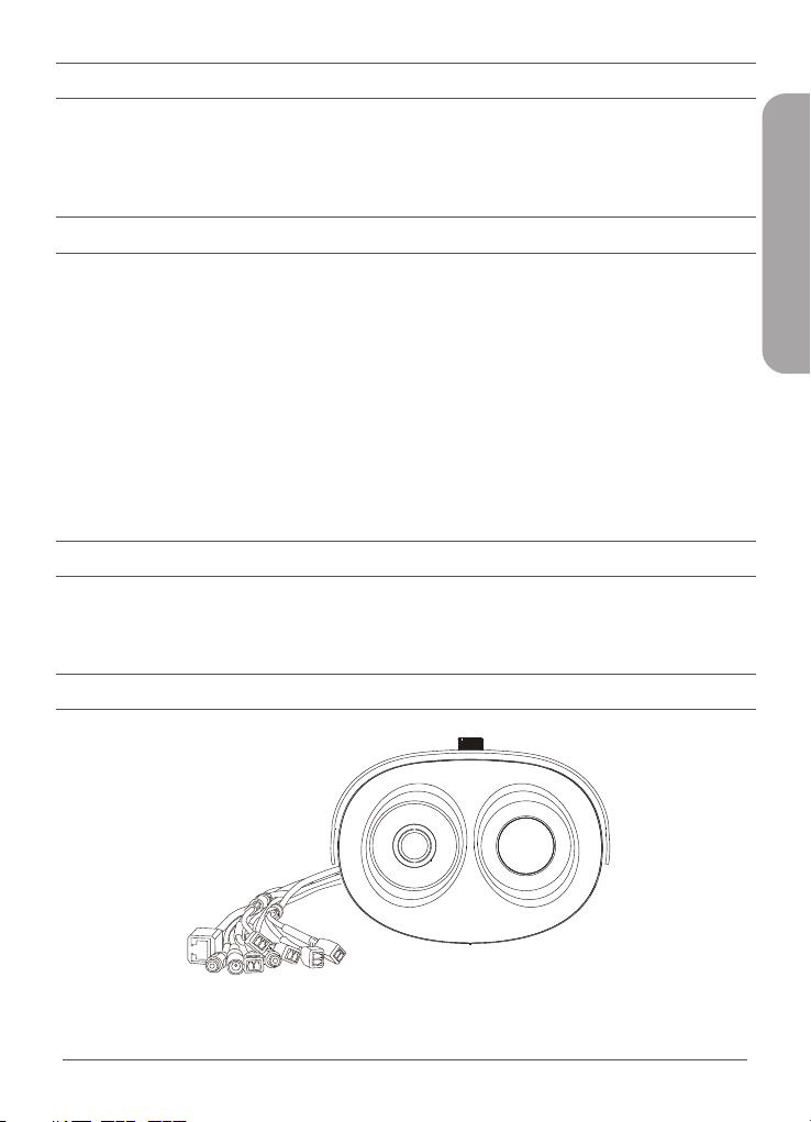
• DCS-9500T Thermal Camera and wall mount
• Blackbody Calibrator and wall mount
• Power Adapter
• Quick Start Guide
Additional optional accessories are also available, please contact your local D-Link reseller for more
information.
If any of the above items are damaged or missing, please contact your local D-Link reseller.
System Requirements
• Windows® operating system
• Internet Explorer 11 or later (for configuration)
Hardware Overview
ENGLISH
DCS-9500T Quick Installation Guide
1
Page 4
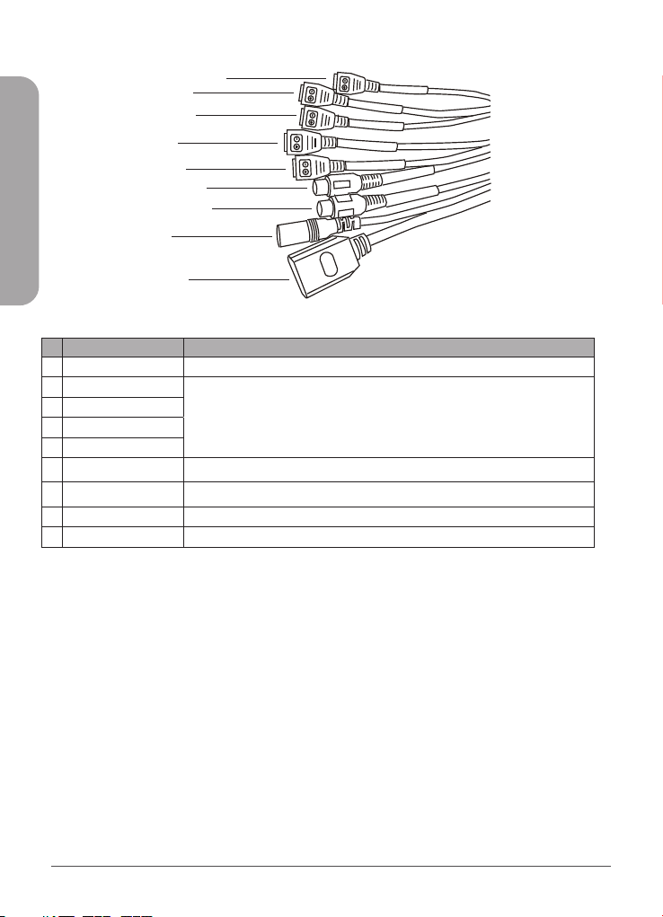
Interface Connectors
1
2
3
4
5
6
7
ENGLISH
8
9
# Cable Core Description
1
2
3
4
5
6
7
8
9
RS485 Connects to external pan and tilt
ALARM IN2 Connects to an alarm device
ALARM OUT2
ALARM IN1
ALARM OUT1
Audio Input
Audio Output
DC12 V Power interface, connects to the 12 V DC power adapter
Network Interface Connects to a standard RJ45 Ethernet cable
Connects to a microphone
Connects to a speaker
2
DCS-9500T Quick Installation Guide
Page 5
Installation
The recommended installation environment is in an airless windless aisle. Please ensure the monitoring
field is far away from any objects that could produce airflow, high temperature or reflection; e.g. a car.
Please do not install opposite of a door, air conditioner or any place where the sun is directly shining.
To ensure temperature measurement accuracy, please install the camera indoors or in a controlled
environment. The measurement might deviate from the actual temperature if the camera is installed
in an open-air environment.
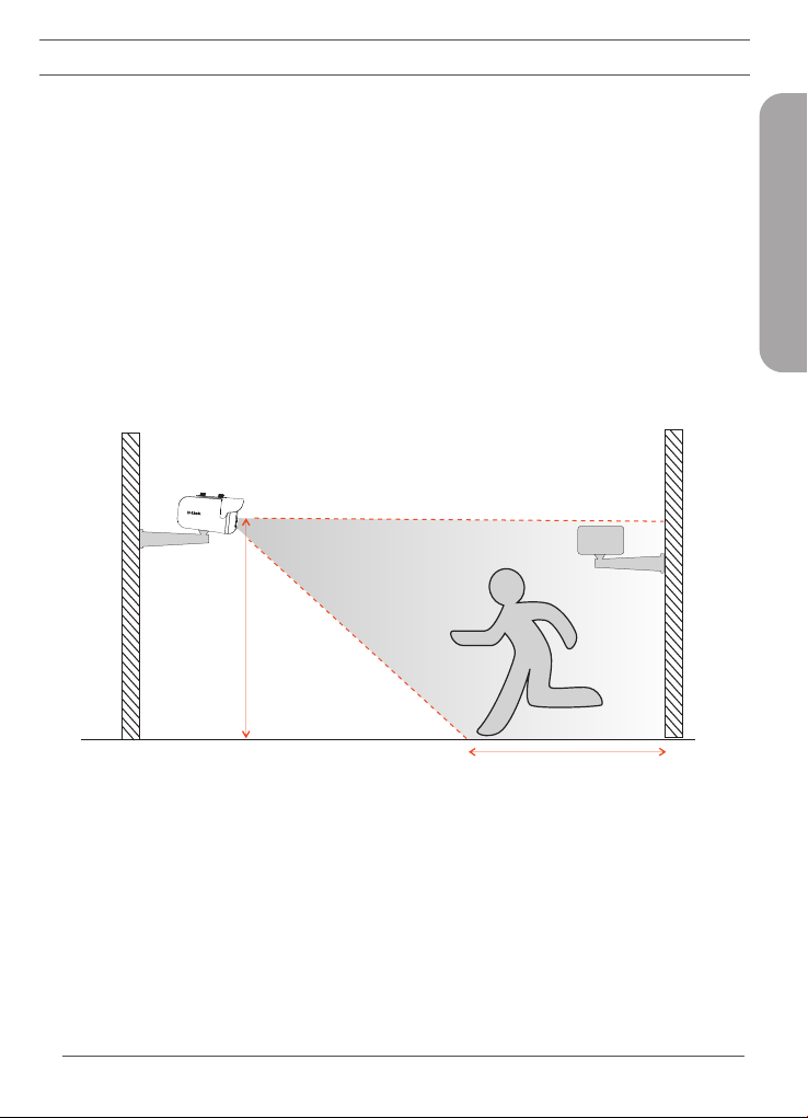
In any installation configuration, the optimal height of the camera is 2-2.3 m from the ground. For optimal
results, the blackbody should be the same height as the camera and 3-5 meters away.
Wall Mount Conguration
2 - 2.3 m
ENGLISH
3 m
1. For wall mounting scenarios, the DCS-9500T should be installed anywhere from 2-2.3 m from
the ground.
2. When installing the blackbody, it is important that it should be installed at the same height as
the camera, 3-5 m in front of the camera (optimally 4 m), and inside the eld of view (FOV)
of the camera. The optimal distance to measure temperature is at the same distance as the
blackbody is installed.
DCS-9500T Quick Installation Guide
5 m
3
Page 6
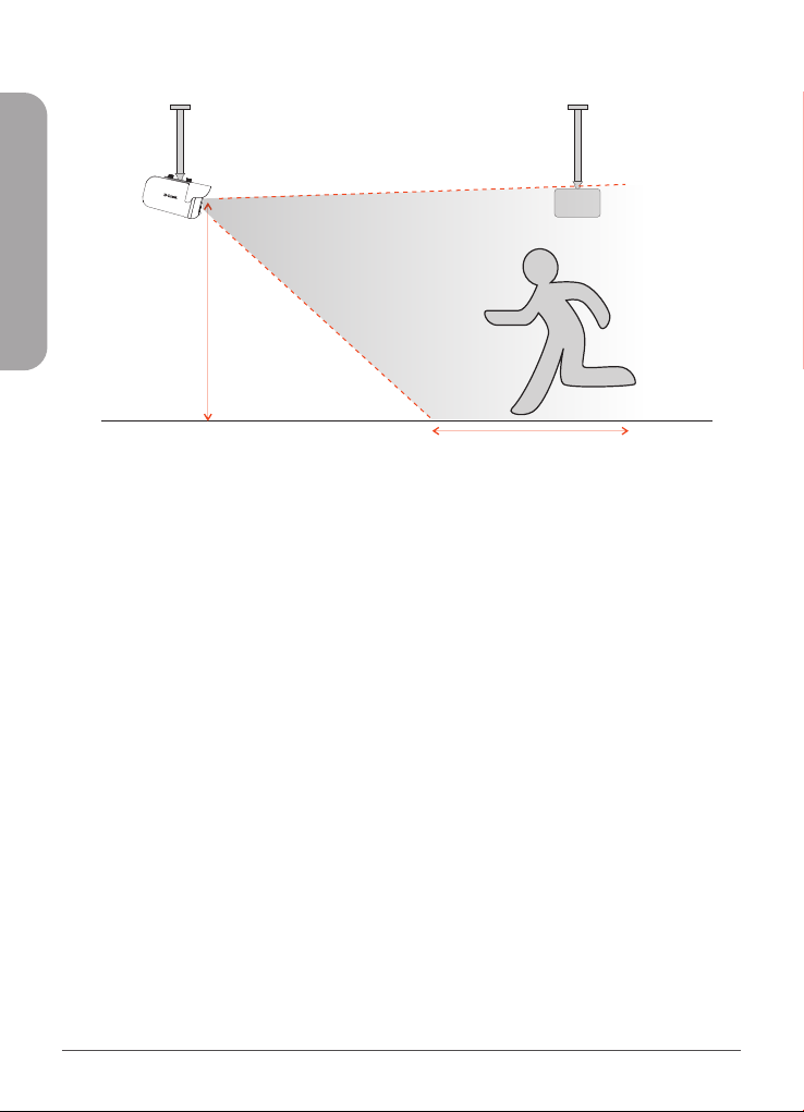
Ceiling Mount Conguration (Optional)
ENGLISH
2 - 2.3 m
3 m 5 m
1. For ceiling mounting scenarios, the DCS-9500T should be installed anywhere from 2-2.3 m from
the ground.
2. When installing the blackbody, it is important that it should be installed at the same height as the
camera, 3-5 m from the camera (optimally 4 m), and inside the eld of view (FOV) of the camera.
The optimal distance to measure temperature is at the same distance as the blackbody is installed.
4
DCS-9500T Quick Installation Guide
Page 7
Web Management Interface (WMI)
You must use Internet Explorer 11 or later to access the web management system; otherwise some
functions may be unavailable.
Logging Into the System
1. Open Internet Explorer.
2. Enter the IP address of the camera (default IP address: 192.168.0.121) in the address box, and
press Enter.
3. After the login page is displayed, input the user name and password. The default name and
password are both admin.
4. You will be prompted to modify the password after you log into the system for the first time.
5. You may change the system display language on the login page to a language of your choice.
6. Click Login. The homepage will be displayed.
Logging Out of the System
1. To logout of system, click the logout icon in the upper right corner of the homepage.
2. The login page will be displayed after you logout of the system.
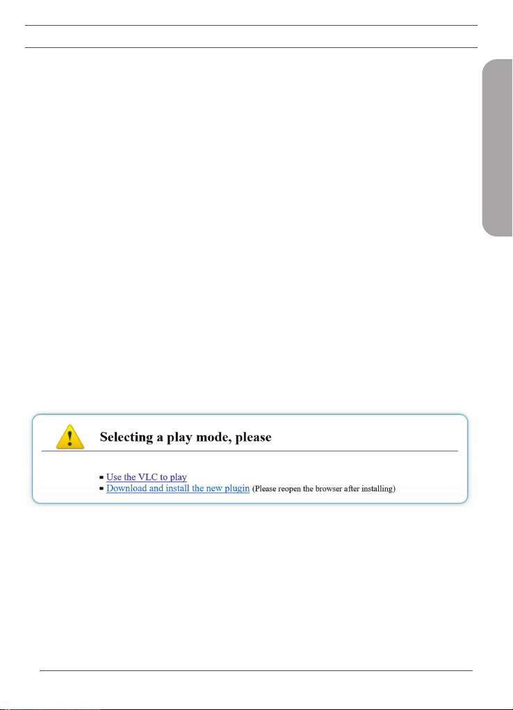
Plugin Installation
ENGLISH
1. If this is your first time using the Web Management Interface, you must first download the latest
plugin. If the latest plugin is not correctly installed, you will not be able to configure parameters,
even if you can view video playback.
2. Please temporarily disable your anti-virus software and close your Internet browser before installing
the plugin.
DCS-9500T Quick Installation Guide
5
Page 8

Temperature Management
ENGLISH
1. Navigate to Conguration > Temperature Measurement.
2. There are 3 main configuration sections that need to be modified; Parameter Configure, Thermal
Mapping, and Thermal Calibration.
Thermal Calibration
Note: It necessary to configure these settings when using the blackbody.
1. Set Enable and Display Area Info to On to enable Thermal Calibration.
2. The Target Temperature should be set to the LED value displayed on the back of the blackbody as
seen above. 40 °C is recommended.
3. Emission Rate is the thermal radiation emissivity of the blackbody. The default value is 0.98.
4. Distance is the distance from the blackbody to the thermal camera.
5. Using the mouse, drag a square over where the blackbody is located on the screen, as seen in the
above image. Note: Be sure that the green square exactly outlines the blackbody for the most
accurate results.
6. Click Apply to save settings.
6
DCS-9500T Quick Installation Guide
Page 9

Thermal Mapping
1. Thermal Mapping overlays the visible and thermal videos to calibrate and synchronize the data
coming from the two separate lenses, corresponding to how accurate the temperature detection
results will be.
2. The goal of Thermal Mapping is to have the green square on the visible camera view match up with
the green square on the thermal camera view that was set in thermal calibration.
3. Use zoom and focus controls found in the red box above to best match the zoom of the thermal
camera view on the right side.
4. Select a Mapping Point. There are three possible points. The more points you calibrate the more
accurate your mapping will be. Match the same color points on the thermal camera view to the
visible camera view.
5. The green box will calibrate itself on the visible camera view based on the Mapping Points on both
thermal and visible camera views.
Note: The closer the green square is to exactly outlining the blackbody, the more accurate your results
will be.
ENGLISH
DCS-9500T Quick Installation Guide
7
Page 10

Face Detection
ENGLISH
1. Under Temperature Measurement, navigate to Parameter Congure.
2. Enable Face Detection and Show Detection Area.
3. Area ID is the number of detection areas. Generally, we only need to set one detection area but
we can optionally set up to 8. For each area, click points on the image to draw a frame over the
target observation area.
4. Face Pixel Min, Face Pixel Max and Image Matting Quality refer to the quality of the face image that
is saved after it is detected. All three can be adjusted according to your system’s requirements.
5. Leave other options at their default values.
6. Refer to the User Manual for more detailed information on each configuration setting.
7. Click Apply to save settings.
Temperature Parameters
1. Set Enable to On to enable temperature detection.
2. Swap between Celcius and Fahrenheit under Temperate Unit. Celsius is set as default.
3. Set the Ambient Temperature to the temperature of the camera’s environment; e.g. indoor
temperature of 25 °C.
8
DCS-9500T Quick Installation Guide
Page 11

4. Mount Distance is the distance between the camera and the target area. Set the distance based
on your own camera setup.
5. Leave other options at their default values.
6. Refer to the User Manual for more detailed information on each configuration setting.
7. Click Apply to save settings.
Alarm Conguration
1. Navigate to Parameter Congure > Face Alarm Linkage. Here you can configure input and output
channels as well as settings for the Face Detection alarm. Be sure to choose an output channel.
2. To set the Alarm Temperature, input a minimum body temperature value into the field. The alarm
will be triggered if the detected temperature exceeds this value.
ENGLISH
3. Navigate to Alarm > I/O Alarm Linkage. Here you can configure your output channel and settings
for the Input/Output alarm. Be sure to choose an output channel.
4. Set Trigger Mode to Connect.
DCS-9500T Quick Installation Guide
9
Page 12
ENGLISH
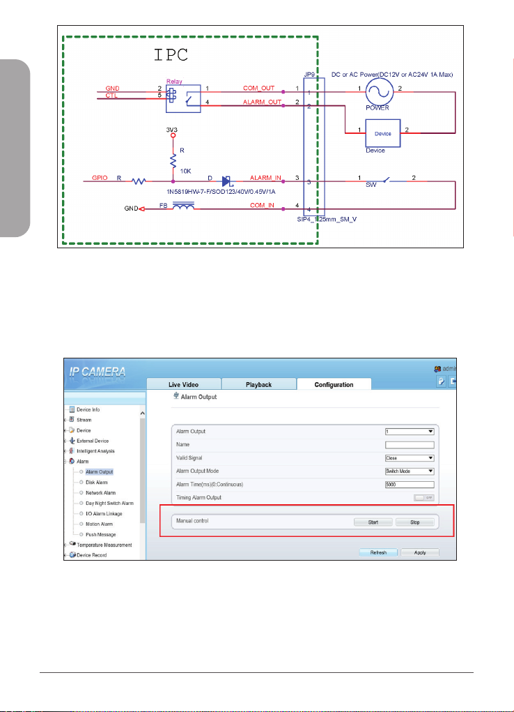
5. Connect your external alarm device to one of the Alarm Out connections on the camera. This
should correspond to the channel selected in Step 1.
6. The diagram above shows how your alarm device should be connected to the output of the
camera. The output does not supply power to the device. Your alarm device’s external power
can be connected in series with the circuit or connected separately to the device. Please see the
above DI/DO diagram above for more information on how to connect your external alarm device.
7. Navigate to Alarm > Alarm Output.
8. Enter a channel name, set Valid Signal to Open, choose an Alarm Output Mode, set the length of
the Alarm Time and optionally enable Timing Alarm Output.
9. Test whether or not you correctly configured the alarms by using the Manual control function.
10
DCS-9500T Quick Installation Guide
Page 13
Content Management System (CMS)
System Installation
1. Double-click on the installation file. The above installation window will pop up.
2. Click Term of service and read the documentation, then check Agree.
3. Click Setup to start the installation and follow the onscreen installation instructions.
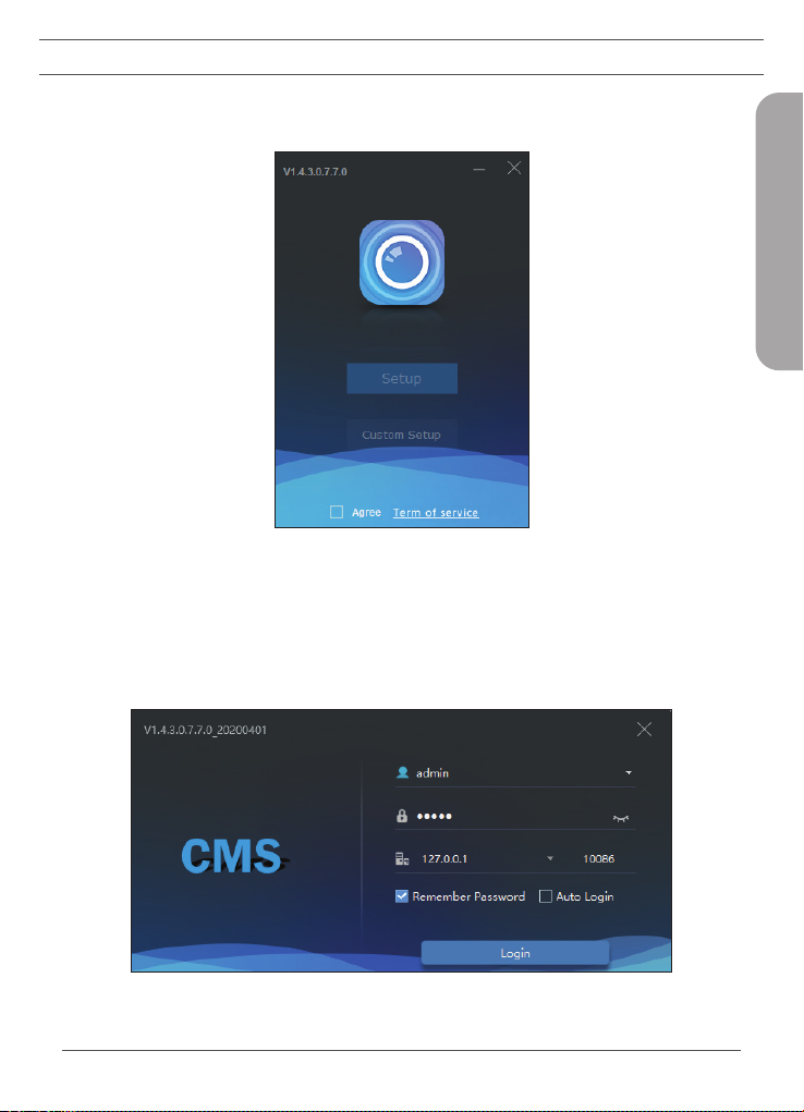
Client Login
ENGLISH
DCS-9500T Quick Installation Guide
11
Page 14
1. The default account and password are both set to admin.
2. The default IP address is 127.0.0. Alternatively, enter the IP address of your central management
server. If the central management server is deployed on another server, please input the server‘s
IP address.
3. You can choose to remember the password or log in automatically according to the user’s
preference.
4. Click Login.
Interface Brief
ENGLISH
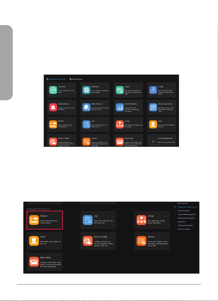
1. CMS is a complete management platform with many different features and functions, all accessible
from the Main Menu seen above.
2. You can use Card Management to add temperature-related functions to the Common Functions
page for convenient access.
Add Device
12
DCS-9500T Quick Installation Guide
Page 15

1. Under All Features, click Devices.
2. Click Add Device at the top of the screen as seen above.
3. Enter your camera’ss details into the add device form. Device Type should be set to Body-Temp
Detector.
4. Click Add to complete the form.
Temperature Screening
1. Navigate to All Features > Temperature Monitor > Temperature Screening.
2. Default Group displays your selectable channels; one for both visible and thermal lenses.
3. Drag each channel into the two panels in the middle of screen so that you can view both the
thermal and visible video streams at the same time.
4. In the Face Recognition side panel, click
in the top right corner.
ENGLISH
DCS-9500T Quick Installation Guide
13
Page 16

ENGLISH
5. Under Full Screen Mode, select Full Screen Face Card, then click OK.
6. Click to enter Full-Screen Mode.
Temperature Conguration
1. Navigate to All Features > Temperature Monitor > Temperature Cong.
2. Set the preset values to acceptable body temperatures and alarm trigger temperatures. All these
settings are based on your system’s regulations.
3. Low Temperature Threshold represents the lowest temperature in the readible range. Detected
body temperatures below this temperature are considered invalid and will not be recorded or
displayed. The default value is 35 °C.
4. High Temperature Threshold represents the highest temperature in the readible range. Detected
body temperatures below this temperature are considered invalid and will not be recorded or
displayed. The default value is 45 °C.
5. Alarm interval is the time between two consecutive alarms. The default value is 60 seconds.
6. Normal Body Temperature is the interval of acceptable body temperatures. Detected body
temperatures in this interval will not trigger an alarm. If the temperature drops below or exceeds
this interval, an alarm will be issued. The default range is between 36.5 °C to 37.8 °C.
7. After all values have been set, click Apply to save your settings.
14
DCS-9500T Quick Installation Guide
Page 17

Over Temperature Alarm Pop-Up Conguration
1. In order to configure alarm settings, navigate to System by clicking in the top right of the user
interface.
2. Under Alarm Message, configure what type of notification to receive when an alarm is triggered.
3. If your camera has sound playback, under Alarm Sound you can configure what type of sound
will play when an alarm is triggered. Choose between Ignore to play no sound, Speech to play a
corresponding voice prompt and Buzzer for a beeping alarm signal.
4. Click Save in the lower right corner to save your configuration.
ENGLISH
TECHNICAL SUPPORT
DCS-9500T Quick Installation Guide
dlink.com/support
15
Page 18

Ver. 1.00(WW)_130x183
2020/03/06
5300-00007657-01W
 Loading...