


410SX
Gas
Operator’s
Manual
CMW
®
Issue 2.2
Original Translation
053-2678

410sx Operator’s Manual Overview - 1
Overview
Chapter Contents
Serial Number Location . . . . . . . . . . . . . . . . . . . . . . 2
Intended Use . . . . . . . . . . . . . . . . . . . . . . . . . . . . . . . 3
Unit Components . . . . . . . . . . . . . . . . . . . . . . . . . . . 4
• Tractor. . . . . . . . . . . . . . . . . . . . . . . . . . . . . . . . . . . . . . . . . . . . . . . . . . . 4
• Plow . . . . . . . . . . . . . . . . . . . . . . . . . . . . . . . . . . . . . . . . . . . . . . . . . . . . 4
• Trencher . . . . . . . . . . . . . . . . . . . . . . . . . . . . . . . . . . . . . . . . . . . . . . . . . 5
• Drill . . . . . . . . . . . . . . . . . . . . . . . . . . . . . . . . . . . . . . . . . . . . . . . . . . . . . 5
• Reel Carrier. . . . . . . . . . . . . . . . . . . . . . . . . . . . . . . . . . . . . . . . . . . . . . . 6
Operator Orientation. . . . . . . . . . . . . . . . . . . . . . . . . 7
About This Manual . . . . . . . . . . . . . . . . . . . . . . . . . . 7
• Bulleted Lists. . . . . . . . . . . . . . . . . . . . . . . . . . . . . . . . . . . . . . . . . . . . . . 7
• Numbered Lists. . . . . . . . . . . . . . . . . . . . . . . . . . . . . . . . . . . . . . . . . . . . 7
CMW
Overview - 2 410sx Operator’s Manual
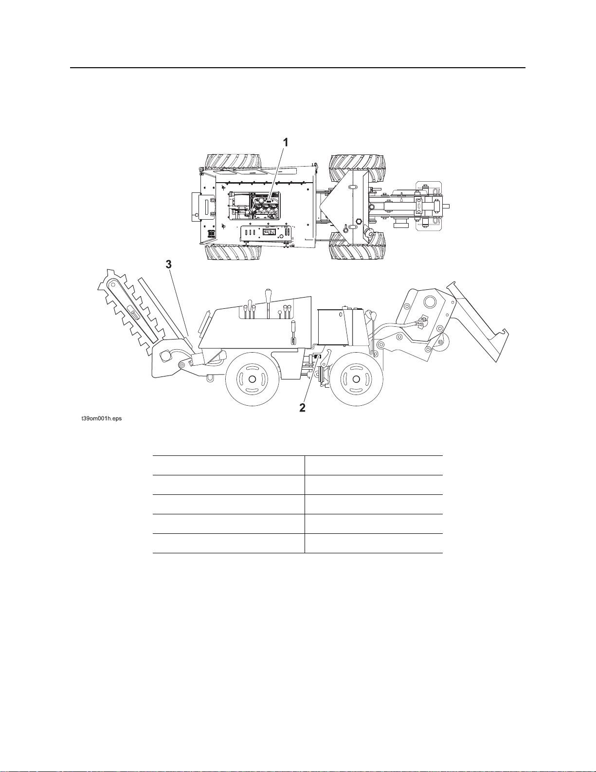
Serial Number Location
Serial Number Location
Record serial numbers and date of purchase in the spaces provided.
CMW
Date of manufacture
Date of purchase
H400 trencher serial number (3)
410sx tractor serial number (2)
Engine serial number (1)

410sx Operator’s Manual Overview - 3
Intended Use
Intended Use
The 410sx is an articulating, hydrostatic, four-wheel drive, pedestrian vibratory plow designed to bury
cable or pipe in a variety of soils. An optional trenching attachment, drilling attachment, and reel carrier are
available. The 410sx is powered by a liquid-cooled 49.6 hp (37.0 kW) four-cylinder Kubota gasoline
engine.
The unit is designed for operation in temperatures typically experienced in excavation and construction
work environments. Provisions may be required to operate in extreme temperatures. Contact your Ditch
Witch dealer. Use in any other way is considered contrary to the intended use.
The H400 trencher should be used with genuine Ditch Witch chain, teeth, and sprockets. The 410sx
should be operated, serviced, and repaired only by persons familiar with its particular characteristics and
acquainted with the relevant safety procedures.
CMW
Overview - 4 410sx Operator’s Manual
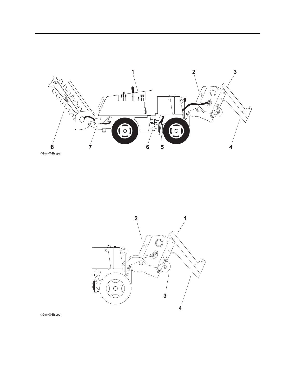
Unit Components
Unit Components
Tractor
1. Operator console
2. Vibrator
3. Feed tube
4. Plow blade
Plow
5. Frame lock
6. Articulation joint
7. Drilling attachment
8. Trencher attachment
1. Feed tube
2. Vibrator
CMW
3. Sod cutter (optional)
4. Plow blade
410sx Operator’s Manual Overview - 5
Unit Components
H400 Trencher
123
4
t39om043w.eps
1. Digging chain
2. Restraint bar
Drill
t39om044w.eps
3. Digging boom
4. Auger
12 3
1. Coupler
2. Zerk
3. U-joint
CMW
Overview - 6 410sx Operator’s Manual
Unit Components
Reel Carrier
1. Front reel carrier
CMW
410sx Operator’s Manual Overview - 7
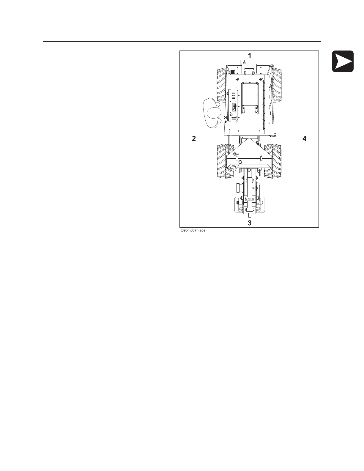
Operator Orientation
Operator Orientation
1. Front of unit
2. Left of unit
Right and left sides of machine are determined by
facing front of unit while standing at the controls.
3. Rear of unit
4. Right of unit
About This Manual
This manual contains information for the proper
use of this machine. See Operation Overview
for basic operating procedures. Cross references
such as “See page 50” will direct you to detailed
procedures.
Bulleted Lists
Bulleted lists provide helpful or important information or contain procedures that do not have to be
performed in a specific order.
Numbered Lists
Numbered lists contain illustration callouts or list steps that must be performed in order.
CMW

Overview - 8 410sx Operator’s Manual
About This Manual
CMW

410sx Operator’s Manual Foreword - 9
Foreword
This manual is an important part of your equipment. It provides safety information and operation
instructions to help you use and maintain your Ditch Witch equipment.
Read this manual before using your equipment. Keep it with the equipment at all times for future reference.
If you sell your equipment, be sure to give this manual to the new owner.
If you need a replacement copy, contact your Ditch Witch dealer. If you need assistance in locating a
dealer, visit our website at www.ditchwitch.com or write to the following address:
The Charles Machine Works, Inc.
Attn: Marketing Department
PO Box 66
Perry, OK 73077-0066
USA
The descriptions and specifications in this manual are subject to change without notice. The Charles
Machine Works, Inc. reserves the right to improve equipment. Some product improvements may have
taken place after this manual was published. For the latest information on Ditch Witch equipment, see your
Ditch Witch dealer.
Thank you for buying and using Ditch Witch equipment.
CMW

Foreword - 10 410sx Operator’s Manual
Machine Works, Inc.
U.S. patent pending.
410sx Gas
Operator’s Manual
Issue number 2.2/OM-01/14
Part number 053-2678
Copyright 2013
by The Charles Machine Works, Inc.
, Ditch Witch, CMW, and Roto Witch are registered trademarks of The Charles
CMW

410sx Operator’s Manual Contents - 11
Contents
Overview
machine serial number, information about the type of work this machine is designed
to perform, basic machine components, and how to use this manual
Foreword
part number, revision level, and publication date of this manual, and factory contact
information
Safety
machine safety alerts and emergency procedures
Controls
machine controls, gauges, and indicators and how to use them
Operation Overview
an overview for completing a job with this machine: planning, setting up, installing
product, and restoring the jobsite; with cross references to detailed procedures
Prepare
procedures for inspecting and classifying the jobsite, planning the installation path,
and preparing the jobsite for work
Drive
procedures for startup, cold start, driving, and shutdown
1
9
11
25
33
37
43
Transport
procedures for lifting, hauling, and towing
Plow
procedures for plowing
Trench
procedures for trenching
Drill
procedures for drilling
Systems and Equipment
ROPS, plow blades, chain, teeth, sprockets, and optional equipment
47
55
61
65
73
CMW

Contents - 12 410sx Operator’s Manual
Complete the Job
procedures for backfilling and restoring the jobsite and rinsing and storing
equipment
Service
service intervals and instructions for this machine including lubrication, replacement
of wear items, and basic maintenance
Specifications
machine specifications including weights, measurements, power ratings, and fluid
capacities
Support
the warranty policy for this machine, and procedures for obtaining warranty
consideration and training
Service Record
a record of major service performed on the machine
79
81
119
125
129
CMW

JT100 Operator’s Manual Safety - 11
Safety
Chapter Contents
Guidelines . . . . . . . . . . . . . . . . . . . . . . . . . . . . . . . . 12
Emergency Procedures . . . . . . . . . . . . . . . . . . . . . 13
• Electric Strike Description. . . . . . . . . . . . . . . . . . . . . . . . . . . . . . . . . . . 13
• If an Electric Line is Damaged . . . . . . . . . . . . . . . . . . . . . . . . . . . . . . . 14
• If a Gas Line is Damaged . . . . . . . . . . . . . . . . . . . . . . . . . . . . . . . . . . . 15
• If a Fiber Optic Cable is Damaged . . . . . . . . . . . . . . . . . . . . . . . . . . . . 16
• If Machine Catches on Fire. . . . . . . . . . . . . . . . . . . . . . . . . . . . . . . . . . 16
Safety Alert Classifications . . . . . . . . . . . . . . . . . . 21
Machine Safety Alerts . . . . . . . . . . . . . . . . . . . . . . 22
CMW®

Safety - 12 JT100 Operator’s Manual
Guidelines
Guidelines
Follow these guidelines before operating any jobsite equipment:
• Complete proper training and read operator’s manual before using equipment.
• Contact your local One-Call (811 in USA) or the One-Call referral number (888-258-0808 in USA and
Canada) to have underground utilities located before digging. Also contact any utilities that do not
participate in the One-Call service. Mark proposed path with white paint prior to contacting One-Call or
utilities.
• Classify jobsite based on its hazards and use correct tools and machinery, safety equipment, and work
methods for jobsite.
• Mark jobsite clearly and keep spectators away.
• Wear personal protective equipment.
• Review jobsite hazards, safety and emergency procedures, and individual responsibilities with all
personnel before work begins. Safety videos are available from your Ditch Witch
• Replace missing or damaged safety shields and safety signs.
• Use equipment carefully. Stop operation and investigate anything that does not look or feel right.
®
dealer.
• Do not operate unit where flammable gas may be present.
• Contact your Ditch Witch dealer if you have any question about operation, maintenance, or equipment
use.
• Complete the equipment checklist located at www.ditchwitch.com/resources/safety.
CMW®
JT100 Operator’s Manual Safety - 13
Emergency Procedures
Emergency Procedures
Jobsite hazards could cause death or serious injury. Use
correct equipment and work methods. Use and maintain proper safety
equipment.
Before operating any equipment, review emergency procedures and check that all safety precautions have
been taken.
EMERGENCY SHUTDOWN - Turn ignition switch to stop position or push remote engine stop button (if
equipped).
Electric Strike Description
Electric shock. Contacting electric lines will cause death or serious injury.
Know location of lines and stay away.
When working near electric cables, remember the following:
• Electricity follows all paths to ground, not just path of least resistance.
• Pipes, hoses, and cables will conduct electricity back to all equipment.
• Low voltage current can injure or kill. Many work-related electrocutions result from contact with less
than 440 volts.
Most electric strikes are not noticeable, but indications of a strike include:
• power outage
• smoke
• explosion
• popping noises
• arcing electricity
If any of these occur, or if strike alarm sounds or flashes, assume an electric strike has occurred.
CMW®

Safety - 14 JT100 Operator’s Manual
Emergency Procedures
If an Electric Line is Damaged
If you suspect an electric line has been damaged and you are on drilling unit or bonded equipment, DO
NOT MOVE. Remain on drilling machine and take the following actions. The order and degree of action will
depend on the situation.
• Warn people nearby that an electric strike has occurred.
• Have someone contact electric company.
• Reverse drilling direction and try to break contact. Do not touch drill pipe with hands or hand-held
tools.
• Press electric strike system self test button.
• If alarm sounds again, stay where you are and wait for electric company to shut off power.
• If alarm does not sound and there is no other indication of a strike, wait at least one full minute
before moving away from equipment. Utility might use automatic reclosers which will restart
current flow. If alarm sounds again while waiting, stay where you are until electric company shuts
off power.
• If alarm does not sound but all lights in strike indicator are on, assume strike is continuing and stay
where you are until electric company shuts off power.
• Do not resume drilling or allow anyone into area until given permission by electric company.
If you suspect an electric line has been damaged and you are off drilling unit or bonded equipment, DO
NOT TOUCH ANY EQUIPMENT connected to drilling unit. Take the following actions. The order and
degree of action will depend on the situation.
• Stay where you are unless you are wearing electric insulating boots. If you leave, do not return to area
or allow anyone into area until given permission by electric company.
CMW®
JT100 Operator’s Manual Safety - 15
Emergency Procedures
If a Gas Line is Damaged
Fire or explosion possible. Fumes could ignite and cause
burns. No smoking, no flame, no spark.
Explosion possible. Serious injury or equipment damage could occur.
Follow directions carefully.
If you suspect a gas line has been damaged, take the following actions. The order and degree of action will
depend on the situation.
• Immediately shut off engine(s), if this can be done safely and quickly.
• Remove any ignition source(s), if this can be done safely and quickly.
• Warn others that a gas line has been cut and that they should leave the area.
• Leave jobsite as quickly as possible.
• Immediately call your local emergency phone number and utility company.
• If jobsite is along street, stop traffic from driving near jobsite.
• Do not return to jobsite until given permission by emergency personnel and utility company.
CMW®

Safety - 16 JT100 Operator’s Manual
Emergency Procedures
If a Fiber Optic Cable is Damaged
Do not look into cut ends of fiber optic or unidentified cable. Vision damage can occur.
If Machine Catches on Fire
Perform emergency shutdown procedure and then take the following actions. The order and degree of
action will depend on the situation.
• Immediately move battery disconnect switch (if equipped and accessible) to disconnect position.
• If fire is small and fire extinguisher is available, attempt to extinguish fire.
• If fire cannot be extinguished, leave area as quickly as possible and contact emergency personnel.
CMW®

410sx Operator’s Manual Safety - 19
Safety Alert Classifications
Safety Alert Classifications
These classifications and the icons defined on the following pages work together to alert you to situations
which could be harmful to you, jobsite bystanders or your equipment. When you see these words and
icons in the book or on the machine, carefully read and follow all instructions. YOUR SAFETY IS AT
STAKE.
Watch for the three safety alert levels: DANGER, WARNING and CAUTION. Learn what each level
means.
indicates a hazardous situation that, if not avoided, will result in death or serious injury.
This signal word is to be limited to the most extreme situations.
indicates a hazardous situation that, if not avoided, could result in death or serious injury.
indicates a hazardous situation that, if not avoided, could result in minor or moderate
injury.
Watch for two other words: NOTICE and IMPORTANT.
NOTICE indicates information considered important, but not hazard-related (e.g., messages relating to
property damage).
IMPORTANT can help you do a better job or make your job easier in some way.
CMW®
Safety - 20 410sx Operator’s Manual
Machine Safety Alerts
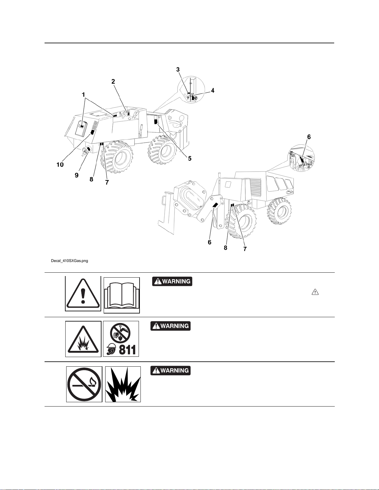
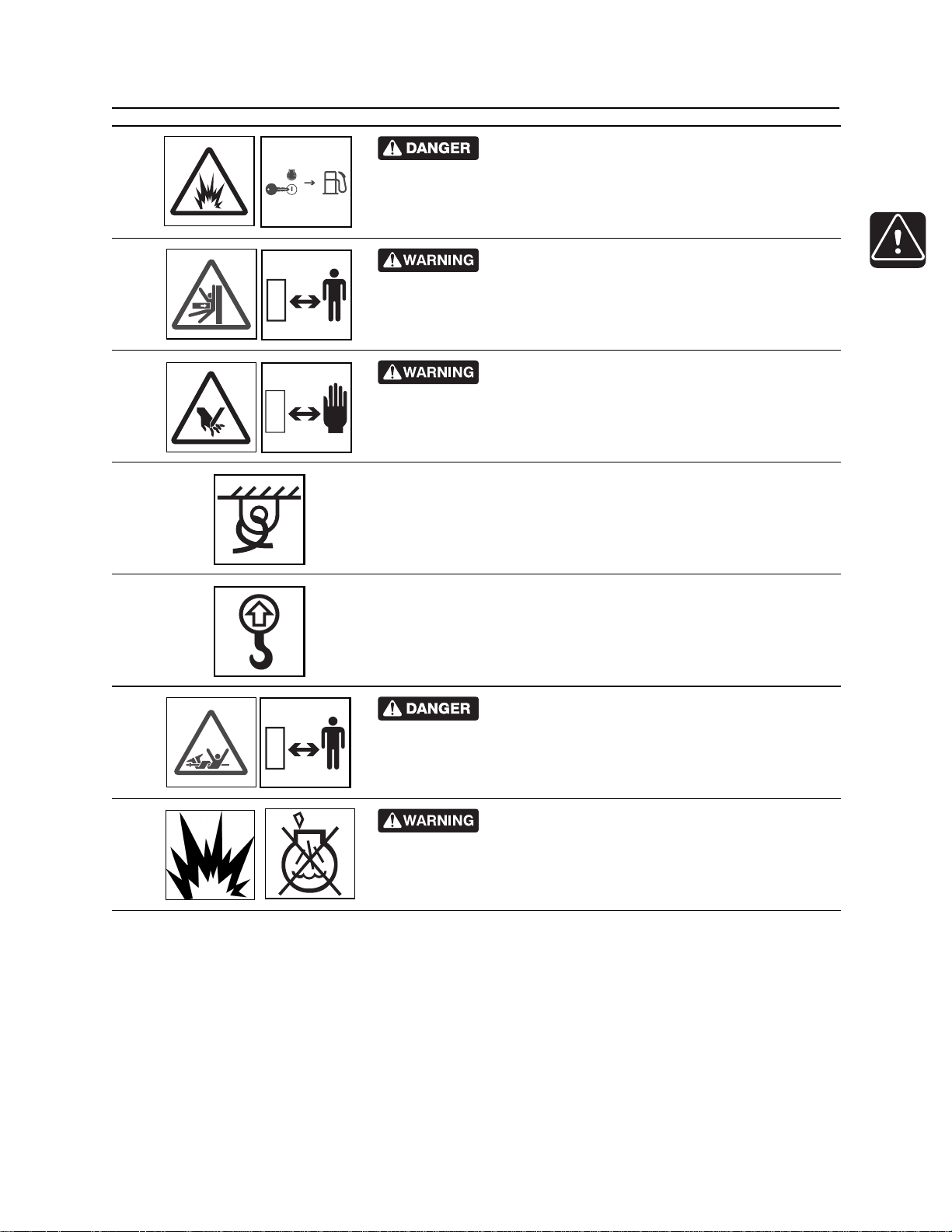
Machine Safety Alerts
Read operator’s manual. Know how to use all
1
2
3
controls before operating machine. When you see this sign on
the machine or in the manual, read it and use caution. Your safety
is at stake.
Jobsite hazards could cause death or serious
injury. Use correct equipment and work methods. Use and maintain
proper safety equipment.
Fire or explosion possible. Fumes could ignite and
cause burns. No smoking, no flame, no spark.
CMW®
410sx Operator’s Manual Safety - 21
Machine Safety Alerts
Fire or explosion possible. Shut engine off before
4
5
6
7
fueling.
Crushing weight could cause death or serious
injury. Use proper procedures and equipment or stay away.
Moving parts could cut off hand or foot. Stay away.
Tiedown location. See Transport chapter for more information.
8
9
10
Lift point. See Transport chapter for more information.
Turning shaft will kill you or crush arm or leg. Stay
away.
Explosion possible. Using starting fluids will cause
ignition in the intake manifold.
CMW®
Safety - 22 410sx Operator’s Manual
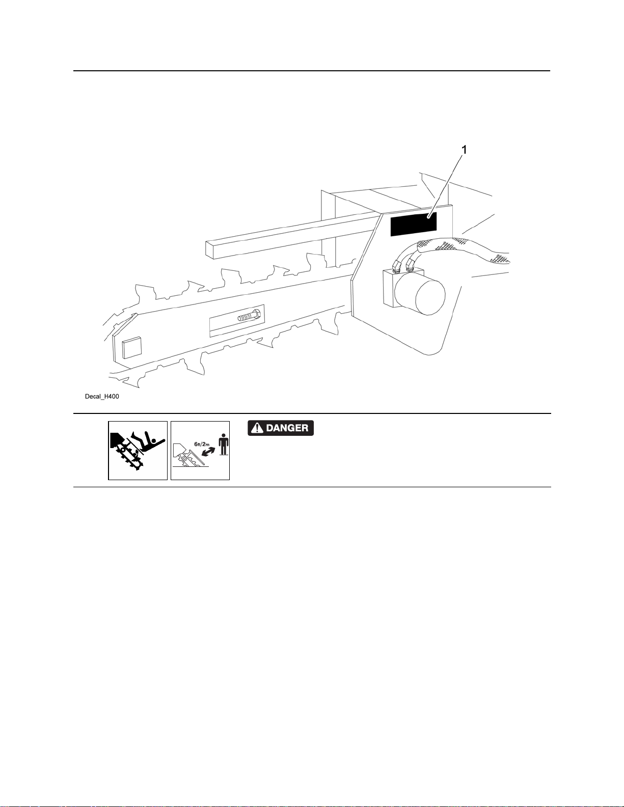
Trencher
Trencher
H400
Moving digging teeth will cause death or serious
1
injury. Trench cave-in can cause you to fall. Stay away.
CMW®
410sx Operator’s Manual Safety - 23
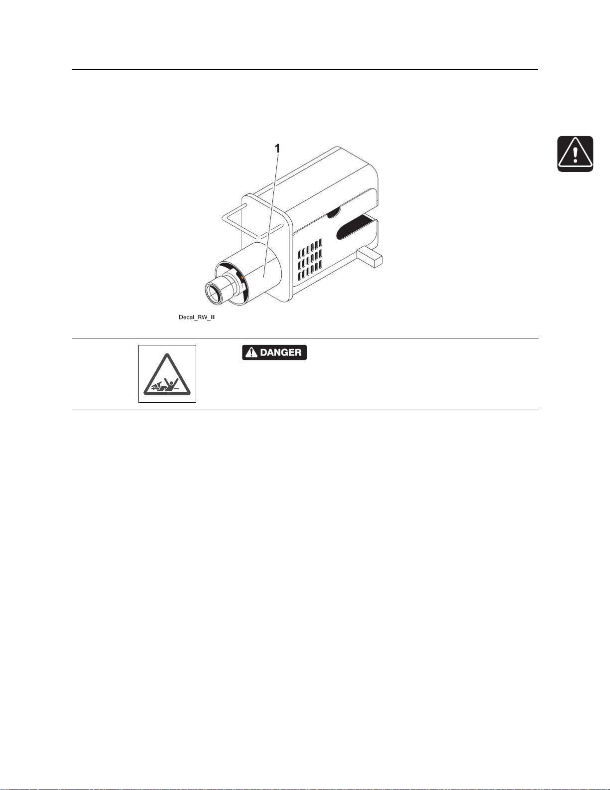
Drilling Attachment
Drilling Attachment
RWIII/RWIV
Turning shaft will kill you or crush arm or leg. Stay
1
away.
CMW®

Safety - 24 410sx Operator’s Manual
Drilling Attachment
CMW®

410sx Operator’s Manual Controls - 25
Controls
Chapter Contents
Tractor . . . . . . . . . . . . . . . . . . . . . . . . . . . . . . . . . . . 26
Attachment . . . . . . . . . . . . . . . . . . . . . . . . . . . . . . . 30
CMW
Controls - 26 410sx Operator’s Manual
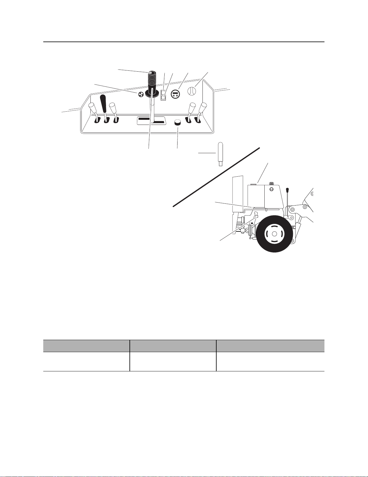
Tractor
Tractor
2345 6
1
t39om001w.eps
1. Alarm speaker
2. Operator presence switch
3. Hydraulic fluid temperature indicator
4. Check engine / Malfunction indicator light (MIL)
5. Engine information display
6. Ignition switch
789
10
11
12
7. Parking brake
8. Throttle control
9. Ground drive speed/direction control
10. Fuel gauge
11. Fuel shutoff valves
12. Frame lock
Item Description Notes
1. Alarm speaker Sounds to alert operator of a
critical malfunction.
CMW
410sx Operator’s Manual Controls - 27
Tractor
Item Description Notes
2. Operator presence
switch
3. Hydraulic fluid
temperature indicator
4. Check engine /
Malfunction indicator
light
Detects when operator is
present.
Press and hold switch before
moving ground drive control
or digging controls out of
neutral.
Lights if hydraulic fluid
overheats.
Lights when an engine
problem has been detected.
If switch is released during operation,
alram will sound and engine will die.
If light remains on:
• Check that engine fan is turning
when engine is running.
• Turn off engine and let it cool.
• Check hydraulic fluid level.
• Check front of hydraulic cooler for
debris.
Lights momentarily when ignition
switch is turned to the ON or START
position.
!
c00ic039w.eps
5. Engine information
display
Displays status of certain
engine functions: RPM,
engine hours, battery voltage,
oil pressure, coolant
temperature, and engine
diagnostic codes.
See “Engine Diagnostic Codes” on
page 78.
“Engine hours” refers to amount of
time key is on position without engine
running. “Machine Hours” refers to
amount of time engine has been
running above 100 rpm.
CMW
Controls - 28 410sx Operator’s Manual
Tractor
Item Description Notes
6. Ignition switch To start engine, insert key and
turn clockwise.
To stop engine, turn counter
clockwise.
7. Parking brake (orange) To engage the parking brake,
push.
To disengage the parking
brake, pull.
8. Throttle To increase engine speed,
turn clockwise.
To decrease engine speed,
turn counterclockwise.
IMPORTANT: If engine does not start
on first attempt, check that all
interlock requirements have been
met, return switch to STOP, and try
again.
c00ic038w.eps
9. Speed/Direction Control To move forward, push
toward F.
To move backward, pull
toward R.
To turn, move control to left or
right.
c00ic002a.eps
To go faster in any direction,
move farther from neutral.
To stop, return to neutral.
CMW
410sx Operator’s Manual Controls - 29
Tractor
Item Description Notes
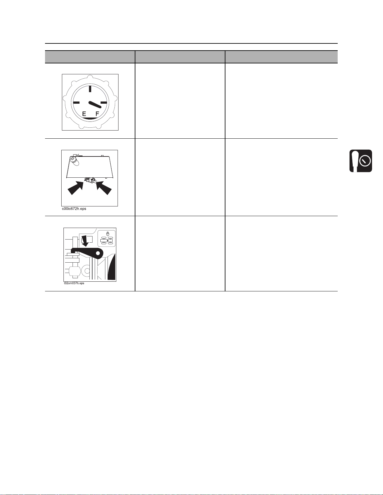
10. Fuel gauge Displays fuel level in tank. Use only approved gasoline fuel.
Fuel tank holds 8.5 gal (32.2 L).
GAS
c00ic040w.eps
11. Fuel shutoff valves Opens and closes fuel line
between tank and engine.
12. Frame lock (yellow) Prevents articulation joint
from moving during transport
or maintenance.
To lock, move lock into gate.
Located under tank on right side.
Valve on the right shuts off fuel return.
Valve on the left shuts off fuel supply.
Use speed/direction control to pivot
unit at articulation joint until lock is
fully engaged.
CMW

Controls - 30 410sx Operator’s Manual
Attachment Controls
Attachment Controls
1. Digging chain control (optional)
2. Drill control (optional)
3. Plow vibrator control
Item Description Notes
1. Digging chain control To start digging chain, push.
To reverse digging chain, pull.
To stop digging chain, return
to neutral position.
c00ic003a.eps
4. Plow lift/lower control
5. Trencher lift/lower control (optional)
6. Plow swing lock
Optional, for use with H400 trenching
attachment.
CMW

410sx Operator’s Manual Controls - 31
Attachment Controls
Item Description Notes
2. Drill direction control To rotate drill string clockwise,
push.
To rotate drill string counter
clockwise, pull.
c00ic007a.eps
3. Plow vibrator control To start, push.
To stop, move to neutral
position.
4. Trencher lift control To lower, push.
To raise, pull.
Optional, for use with Roto Witch
drilling attachment.
Optional, for use with H400 trenching
attachment.
5. Plow lift control To lower, push.
To raise, pull.
CMW

Controls - 32 410sx Operator’s Manual
Attachment Controls
Item Description Notes
6. Plow swing lock (blue) To engage plow swing lock,
move control toward tractor.
To disengage, move control
toward plow.
CMW

410sx Operator’s Manual Operation Overview - 33
Operation Overview
Chapter Contents
Planning. . . . . . . . . . . . . . . . . . . . . . . . . . . . . . . . . . 34
Plowing . . . . . . . . . . . . . . . . . . . . . . . . . . . . . . . . . . 34
Trenching. . . . . . . . . . . . . . . . . . . . . . . . . . . . . . . . . 34
Drilling . . . . . . . . . . . . . . . . . . . . . . . . . . . . . . . . . . . 35
Leaving Jobsite. . . . . . . . . . . . . . . . . . . . . . . . . . . . 35
CMW

Operation Overview - 34 410sx Operator’s Manual
Planning
Planning
1. Gather information about jobsite. See page 38.
2. Inspect jobsite. See page 39.
3. Classify jobsite. See page 40.
4. Select plow blade for your installation. See page 75
5. Select chain and teeth to match your soil type, if necessary. See page 76.
6. Check supplies and prepare equipment. See page 42.
7. Haul equipment to jobsite. See page 50.
Plowing
1. Start unit. See page 44.
2. Position tractor and controls. See page 57.
3. Attach product. See page 57.
4. Begin plowing. See page 58.
5. Complete the installation. See page 79.
6. Shut down tractor. See page 45.
Trenching
1. Start unit. See page 44.
2. Position tractor and controls. See page 62.
3. Begin trenching. See page 63.
4. Complete the installation. See page 79.
5. Shut down tractor. See page 45.
CMW

410sx Operator’s Manual Operation Overview - 35
Drilling
Drilling
1. Start unit. See page 44.
2. Dig approach trench and target trench. See page 67.
3. Assemble drill string and position tractor. See page 67.
4. Begin drilling. See page 69.
5. Use drill string guide as needed. See page 70.
6. Add rod. See page 71.
7. Backream. See page 71.
8. Shut down tractor. See page 45.
9. Disassemble joints. See page 72.
Leaving Jobsite
1. Restore jobsite. See page 80.
2. Rinse equipment. See page 80.
3. Stow tools. See page 80.
4. Haul equipment away from jobsite. See page 50.
CMW

Operation Overview - 36 410sx Operator’s Manual
Leaving Jobsite
CMW

410sx Operator’s Manual Prepare - 37
Prepare
Chapter Contents
Gather Information . . . . . . . . . . . . . . . . . . . . . . . . . 38
• Review Job Plan . . . . . . . . . . . . . . . . . . . . . . . . . . . . . . . . . . . . . . . . . . 38
• Notify One-Call Services. . . . . . . . . . . . . . . . . . . . . . . . . . . . . . . . . . . . 38
• Arrange for Traffic Control. . . . . . . . . . . . . . . . . . . . . . . . . . . . . . . . . . . 38
• Plan for Emergency Services . . . . . . . . . . . . . . . . . . . . . . . . . . . . . . . . 38
Inspect Site . . . . . . . . . . . . . . . . . . . . . . . . . . . . . . . 39
• Identify Hazards . . . . . . . . . . . . . . . . . . . . . . . . . . . . . . . . . . . . . . . . . . 39
Classify Jobsite. . . . . . . . . . . . . . . . . . . . . . . . . . . . 40
• Inspect Jobsite . . . . . . . . . . . . . . . . . . . . . . . . . . . . . . . . . . . . . . . . . . . 40
• Select a Classification. . . . . . . . . . . . . . . . . . . . . . . . . . . . . . . . . . . . . . 40
• Apply Precautions. . . . . . . . . . . . . . . . . . . . . . . . . . . . . . . . . . . . . . . . . 41
Check Supplies and Prepare Equipment . . . . . . . 42
• Supplies . . . . . . . . . . . . . . . . . . . . . . . . . . . . . . . . . . . . . . . . . . . . . . . . 42
• Fluid Levels. . . . . . . . . . . . . . . . . . . . . . . . . . . . . . . . . . . . . . . . . . . . . . 42
• Condition and Function. . . . . . . . . . . . . . . . . . . . . . . . . . . . . . . . . . . . . 42
• Accessories. . . . . . . . . . . . . . . . . . . . . . . . . . . . . . . . . . . . . . . . . . . . . . 42
CMW

Prepare - 38 410sx Operator’s Manual
Gather Information
Gather Information
A successful job begins before you dig. The first step in planning is reviewing information already available
about the job and jobsite.
Review Job Plan
Review blueprints or other plans. Check for information about existing or planned structures, elevations, or
proposed work that may be taking place at the same time.
Notify One-Call Services
Contact your local One-Call (811 in USA) or the One-Call referral number (888-258-0808 in USA and
Canada) to have underground utilities located before digging. Also contact any utilities that do not
participate in the One-Call service.
Arrange for Traffic Control
If working near a road or other traffic area, contact local authorities about safety procedures and
regulations.
Plan for Emergency Services
Have the telephone numbers for local emergency and medical facilities on hand. Check that you will have
access to a telephone.
CMW

410sx Operator’s Manual Prepare - 39
Inspect Site
Inspect Site
Inspect jobsite before transporting equipment. Check for the following:
• changes in elevation such as hills or other open trenches
• obstacles such as buildings, railroad crossings, or streams
• signs of utilities (See “Inspect Jobsite” on page 40.)
• traffic
• access
• soil type and condition
Identify Hazards
Identify safety hazards and classify jobsite. See “Classify Jobsite” on page 40.
Jobsite hazards could cause death or serious injury. Use
correct equipment and work methods. Use and maintain proper safety
equipment.
To help avoid injury:
• Wear personal protective equipment including hard hat, safety eye wear, and hearing protection.
• Do not wear jewelry or loose clothing.
• Notify One-Call and companies which do not subscribe to One-Call.
• Comply with all utility notification regulations before digging or drilling.
• Verify location of previously marked underground hazards.
• Mark jobsite clearly and keep spectators away.
Remember, jobsite is classified by hazards in place -- not by line being installed.
CMW

Prepare - 40 410sx Operator’s Manual
Classify Jobsite
Classify Jobsite
Inspect Jobsite
• Follow U.S. Department of Labor regulations on excavating and trenching (Part 1926, Subpart P) and
other similar regulations.
• Contact your local One-Call (811 in USA) or the One-Call referral number (888-258-0808 in USA and
Canada) to have underground utilities located before digging. Also contact any utilities that do not
participate in the One-Call service.
• Inspect jobsite and perimeter for evidence of underground hazards, such as:
– “buried utility” notices
– utility facilities without overhead lines
– gas or water meters
– junction boxes
– drop boxes
– light poles
– manhole covers
– sunken ground
• Have an experienced locating equipment operator sweep area within 20’ (6 m) to each side of trench
path. Verify previously marked line and cable locations.
• Mark location of all buried utilities and obstructions.
• Classify jobsite.
Select a Classification
Jobsites are classified according to underground hazards present.
If working... then classify jobsite as...
within 10’ (3 m) of a buried electric line electric
within 10’ (3 m) of a natural gas line natural gas
in sand, granite, or concrete which is capable of producing
crystalline silica (quartz) dust
within 10’ (3 m) of any other hazard other
NOTICE: If you have any doubt about jobsite classification, or if jobsite might contain unmarked
hazards, take steps outlined previously to identify hazards and classify jobsite before working.
crystalline silica (quartz) dust
CMW

410sx Operator’s Manual Prepare - 41
Classify Jobsite
Apply Precautions
Once classified, precautions appropriate for jobsite must be taken.
Electric Jobsite Precautions
Use one or both of these methods.
• Expose line by careful hand digging or soft excavation.
• Have service shut down while work is in progress. Have electric company test lines before returning
them to service.
Natural Gas Jobsite Precautions
In addition to positioning equipment upwind from gas lines, use one or both of these methods.
• Expose lines by careful hand digging or soft excavation.
• Have gas shut off while work is in progress. Have gas company test lines before returning them to
service.
Crystalline Silica (Quartz) Dust Precautions
Jobsite hazards could cause death or serious injury. Use correct
equipment and work methods. Use and maintain proper safety equipment.
Cutting, drilling or working materials such as concrete, sand, or rock containing quartz
may result in exposure to silica dust. Silica dust may cause lung disease and is known to
the State of California to cause cancer.
To help avoid injury:
• Use water spray or other means to control dust.
• If workers are exposed to dust, they must wear appropriate breathing protection.
Other Jobsite Precautions
You may need to use different methods to safely avoid other underground hazards. Talk with those
knowledgeable about hazards present at each site to determine which precautions should be taken or if
job should be attempted.
CMW

Prepare - 42 410sx Operator’s Manual
Check Supplies and Prepare Equipment
Check Supplies and Prepare Equipment
Supplies
• fuel
• keys
• personal protective equipment, such as hard hat and safety glasses
Fluid Levels
• fuel
• hydraulic fluid
• battery charge
• engine oil
Condition and Function
• digging chain and teeth
• fan belts
• light bulbs
• filters (air, oil, hydraulic)
• tires
• pumps and motors
• hoses and valves
• signs, guards, and shields
Accessories
Fire Extinguisher
If required, mount a fire extinguisher near the power unit but away from possible points of ignition. The fire
extinguisher should always be classified for both oil and electric fires. It should meet legal and regulatory
requirements.
CMW

410sx Operator’s Manual Drive - 43
Drive
Chapter Contents
Start Unit . . . . . . . . . . . . . . . . . . . . . . . . . . . . . . . . . 44
Drive. . . . . . . . . . . . . . . . . . . . . . . . . . . . . . . . . . . . . 45
Shut Down . . . . . . . . . . . . . . . . . . . . . . . . . . . . . . . . 45
CMW
Drive - 44 410sx Operator’s Manual
Start Unit
Start Unit
Before operating tractor, read engine manufacturer’s starting and operating instructions. Follow
instructions for new engine break-in.
Runaway possible. Machine could run over you or others. Learn how to
use all controls. Start and operate only from operator’s position.
Read operator’s manual. Know how to use all controls
before operating machine. When you see this sign on the machine or
in the manual, read it and use caution. Your safety is at stake.
To help avoid injury:
• Read operator’s manual before operating equipment. Follow instructions carefully. Contact your
Ditch Witch dealer for operation information or demonstration.
• Wear hard hat, safety glasses, and other protective equipment required by job. Do not wear jewelry
or loose clothing that can catch on controls.
1. Move all controls and switches to the neutral or disengaged position.
2. Verify that parking brake is engaged.
3. Insert key into ignition switch and turn to the ON position.
4. Verify that check engine light (engine malfunction indicator) is on.
5. Set throttle at low idle.
6. Turn ignition switch to START position. Release key when engine starts.
7. Verify that check engine light (engine malfunction indicator light) is off. If not, stop engine by turning
ignition switch to OFF position. Check for cause of engine malfunction.
8. Run engine at half-throttle or less for five minutes before operating tractor. During warm-up, check that
all controls work properly.
CMW

410sx Operator’s Manual Drive - 45
Shut Down
Drive
Tipover possible. Machine can tip over and crush you.
To help avoid injury:
• Always operate so that operator is on uphill side of machine.
• Keep digging boom low when operating or transporting on a slope.
• Never jerk control levers. Use a steady even motion.
• Drive slowly and cautiously at all times.
EMERGENCY SHUTDOWN: Turn ignition switch to STOP.
1. Raise attachments for ground clearance. Ensure that plow swing lock is engaged.
2. Check that tires are positioned straight or in direction of intended movement.
3. Release parking brake.
4. Press and hold operator presence switch.
5. Move ground drive control in desired direction of travel.
6. Adjust throttle for desired speed of travel.
Shut Down
1. When job is complete, move ground drive control to neutral.
NOTICE: Machine should not be parked on a slope unless chocked, blocked, or parking brake
engaged.
2. Return all controls to neutral or disengaged position.
3. Engage parking brake.
4. Lower all attachments to ground.
5. Move throttle to low idle for 2-3 minutes to cool.
6. Turn ignition switch to OFF position. If leaving machine unattended, remove key.
7. For maintenance or long-term storage, turn battery disconnect switch, if equipped, to the disconnect
position.
CMW

Drive - 46 410sx Operator’s Manual
Shut Down
CMW

410sx Operator’s Manual Transport - 47
Transport
Chapter Contents
Lift . . . . . . . . . . . . . . . . . . . . . . . . . . . . . . . . . . . . . . 48
• Points . . . . . . . . . . . . . . . . . . . . . . . . . . . . . . . . . . . . . . . . . . . . . . . . . . 48
• Procedure . . . . . . . . . . . . . . . . . . . . . . . . . . . . . . . . . . . . . . . . . . . . . . . 48
Haul . . . . . . . . . . . . . . . . . . . . . . . . . . . . . . . . . . . . . 50
Tie Down . . . . . . . . . . . . . . . . . . . . . . . . . . . . . . . . . 51
• Points . . . . . . . . . . . . . . . . . . . . . . . . . . . . . . . . . . . . . . . . . . . . . . . . . . 51
• Procedure . . . . . . . . . . . . . . . . . . . . . . . . . . . . . . . . . . . . . . . . . . . . . . . 51
Tow . . . . . . . . . . . . . . . . . . . . . . . . . . . . . . . . . . . . . 53
CMW

Transport - 48 410sx Operator’s Manual
Lift
Lift
Crushing weight. If load falls or moves it could kill or crush you. Use
proper procedures and equipment or stay away.
Points
Lifting points are identified by lifting decals. Lifting at other points is unsafe
and can damage machinery.
Procedure
Tractor
Use a crane capable of supporting the
equipment's size and weight. See “410sx” on
page 119.
• Engage frame lock. See page 26.
• Use indicated lift points.
• Do not attempt to lift tractor with
attachments installed.
CMW

410sx Operator’s Manual Transport - 49
Lift
H400 Trencher
Use crane capable of supporting the
equipment's size and weight. See page 119 or
measure and weigh equipment before lifting.
NOTICE: Do not lift tractor with attachments
installed.
t39om047w.eps
Reel Carrier
Use crane capable of supporting the
equipment's size and weight. See page 119 or
measure and weigh equipment before lifting.
NOTICE: Do not lift tractor with attachments
installed.
t39om048w.eps
CMW

Transport - 50 410sx Operator’s Manual
Haul
Haul
Load
Crushing weight. If load falls or moves it could kill or crush you. Use
proper procedures and equipment or stay away.
To help avoid injury:
• Load unit with engine in low idle and boom as low as possible.
• Load trailer on level ground.
• Load trailer correctly to avoid trailer swaying.
• Attach trailer to vehicle before loading or unloading.
• If loading onto a tilt-bed trailer, ensure that tilt latch is secured in the correct position.
• Ten to fifteen percent of total vehicle weight (equipment plus trailer) must be on tongue to help
prevent trailer sway.
1. Start engine. See page 44 for proper start-up procedures.
2. Raise trencher boom, but keep it low.
3. Fully raise or remove plow blade and ensure that plow swing lock is engaged.
4. Release parking brake.
5. Slowly drive tractor onto trailer.
6. Position tractor on trailer deck for proper weight distribution.
7. Engage parking brake.
8. Lower attachments to trailer bed and turn tractor off. See page 45 for proper shutdown procedures.
9. Engage frame lock.
10. Attach chains to tractor and attachments where tie-down decals are located. See page 51.
CMW

410sx Operator’s Manual Transport - 51
Tie Down
Tie Down
Points
Tie-down points are identified by tie-down decals. Securing to trailer at
other points is unsafe and can damage machinery.
Procedure
Attach chains at front and rear tie-down points.
Make sure chains are tight before transporting
unit.
CMW

Transport - 52 410sx Operator’s Manual
Tie Down
Unload
Crushing weight. If load falls or moves it could kill or crush you. Use
proper procedures and equipment or stay away.
To help avoid injury:
• Unload unit with engine in low idle and boom as low as possible.
• Unload trailer on level ground.
• Attach trailer to vehicle before loading or unloading.
• If trailer tilts, ensure that tilt latch is secured in the correct position.
1. Lower trailer or ramps.
2. Remove chains from tiedowns.
3. Start tractor. See page 44 for proper start-up procedures.
4. Raise trencher boom, but keep it low.
5. Fully raise or remove plow blade and ensure that plow swing lock is engaged.
6. Disengage frame lock.
7. Disengage parking brake.
8. Slowly back unit down trailer or ramps.
CMW

410sx Operator’s Manual Transport - 53
Tow
Tow
Under normal conditions, tractor should not be towed. If tractor becomes disabled and towing is
necessary:
• Open hydrostat bypass valve.
• Do not tow for more than 200 yd (180 m).
• Tow at less than 1-2 mph (1.5-3.0 km/h).
• Unit cannot be steered as it is towed.
• Use maximum towing force of 1.5 times unit weight.
Procedure
1. Attach tow line to all available tie-down points
facing towing vehicle.
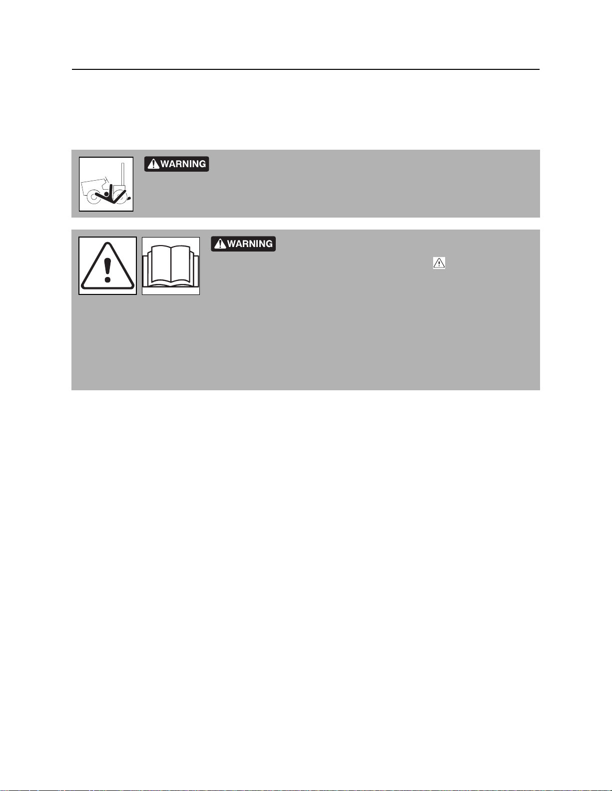
2. Check that all controls are in neutral position.
3. Open valve (shown) by turning cartridge 1/4
turn so that flat sides are horizontal.
4. Move speed/direction control in direction of
travel.
5. Disengage parking brake.
Return Unit to Normal Operation
1. Engage parking brake.
t39om055w.eps
2. Block wheels.
3. Disconnect from tow point.
4. Turn tow valve cartridge to original position.
CMW

Transport - 54 410sx Operator’s Manual
Tow
CMW

410sx Operator’s Manual Plow - 55
Plow
Chapter Contents
Setup . . . . . . . . . . . . . . . . . . . . . . . . . . . . . . . . . . . . 56
• Position Tractor. . . . . . . . . . . . . . . . . . . . . . . . . . . . . . . . . . . . . . . . . . . 57
• Attach Product. . . . . . . . . . . . . . . . . . . . . . . . . . . . . . . . . . . . . . . . . . . . 57
Operation. . . . . . . . . . . . . . . . . . . . . . . . . . . . . . . . . 58
CMW

Plow - 56 410sx Operator’s Manual
Setup
Setup
EMERGENCY SHUTDOWN - Turn ignition switch to STOP.
Crushing weight could cause death or serious injury. Use
proper procedures and equipment or stay away.
To help avoid injury: Keep everyone at least 6’ (2 m) from machine, attachments, and their range of
movement.
Jobsite hazards could cause death or serious injury. Use
correct equipment and work methods. Use and maintain proper safety
equipment.
To help avoid injury: Comply with all utility notification regulations before digging or drilling.
Read operator’s manual. Know how to use all controls before operating
machine. When you see this sign on the machine or in the manual, read it and use
caution. Your safety is at stake.
To help avoid injury: Use attachments or counterweights to make front and rear loads balance when all
attachments are raised. Contact your Ditch Witch dealer about counterweighting for your equipment.
NOTICE:
• Choose the correct plow blade length for the desired depth of material cover. If using a vertically
adjustable, multi-depth blade, select the proper installation height.
• Do not operate vibrator unless plow blade is in the ground.
CMW

410sx Operator’s Manual Plow - 57
Setup
Position Tractor
1. Start tractor. See page 44 for start-up procedures.
2. Drive to starting point. Move in line with planned path. See page 45 for operating procedures.
3. Engage parking brake.
4. Lower plow blade to starting point of path.
5. Turn ignition switch to STOP.
Attach Product
To Pull Product
1. Insert material into pulling grip.
2. Tape grip with duct tape.
To Feed Product
1. Remove cable guide.
2. Feed cable through tube from top to
bottom.
3. Replace cable guide and tighten
fasteners.
4. Secure cable.
NOTICE: Keep everyone away from
material being installed.
CMW

Plow - 58 410sx Operator’s Manual
Operation
Operation
Crushing weight could cause death or serious injury. Use proper
procedures and equipment or stay away.
Electrical shock. Contacting electrical lines will cause death or serious
injury. Know location of lines and stay away.
To help avoid injury: Expose lines by hand before digging. Cutting high voltage cable can cause
electrocution
Read operator’s manual. Know how to use all controls before operating
machine. When you see this sign on the machine or in the manual, read it and use
caution. Your safety is at stake.
NOTICE:
• Do NOT plow with the blade partially raised. Only operate the plow with blade fully in the ground.
• Do NOT move ground drive control to reverse with the blade in the ground.
CMW

410sx Operator’s Manual Plow - 59
Operation
Start Plowing
Tipover possible. Machine can tip over and crush you.
To help avoid injury:
• Always operate so that operator is on uphill side of machine.
• Keep digging boom low when operating or transporting on a slope.
• Never jerk control levers. Use a steady even motion.
• Drive slowly and cautiously at all times.
1. Start unit. (See “Start Unit” on page 44.)
2. Adjust throttle to low idle.
3. Check that ground drive control is in neutral.
4. Disengage parking brake.
5. Move ground drive control forward to a slow speed and lower plow blade until it begins to break the
soil.
6. Move the plow vibrator control to the ON position. PLOW WILL VIBRATE.
NOTICE:
• Move slowly while lowering the plow blade into the ground.
• Do NOT move ground drive control to reverse with the blade in the ground.
• Do NOT plow with the blade partially raised.
7. Lower the plow blade into the ground to full
depth.
8. Increase engine speed to a point with the least
tractor vibration and the highest ground drive
speed possible without tire slippage.
9. Check cable for damage during plowing. Run
continuity checks on electric cable and check
pipe pressure. Damage can result from
improper operation, incorrect blade choice,
striking underground obstructions, or other
conditions.
t39om051w.eps
CMW

Plow - 60 410sx Operator’s Manual
Operation
Finish Plowing
1. When installation is complete, move ground drive control to the neutral position.
2. With vibrator running, lower throttle speed and raise plow to just below ground level.
3. Move plow vibrator control to OFF.
NOTICE: Do not operate vibrator when plow is out of the ground. This will cause excessive
vibration and will cause rapid wear, and possible damage to the unit and product being
installed.
4. Engage plow swing lock.
5. Raise plow out of ground.
6. Engage parking brake.
7. Turn ignition switch to OFF and remove product from plow.
8. Start tractor and drive a short distance away from work site.
9. Shut down tractor. See page 45 for proper shutdown procedures.
CMW

410sx Operator’s Manual Trench - 61
Trench
Chapter Contents
Setup . . . . . . . . . . . . . . . . . . . . . . . . . . . . . . . . . . . . 62
Operation. . . . . . . . . . . . . . . . . . . . . . . . . . . . . . . . . 63
CMW

Trench - 62 410sx Operator’s Manual
Setup
Setup
EMERGENCY SHUTDOWN - Release button on operator presense handle and turn ignition switch to
OFF position.
Crushing weight could cause death or serious injury. Use
proper procedures and equipment or stay away.
To help avoid injury: Use attachments or counterweights to make front and rear loads balance when all
attachments are raised. Contact your Ditch Witch dealer about counterweighting for your equipment.
Jobsite hazards could cause death or serious injury. Use
correct equipment and work methods. Use and maintain proper safety
equipment.
To help avoid injury: Comply with all utility notification regulations before digging or drilling.
Read operator’s manual. Know how to use all controls before operating
machine. When you see this sign on the machine or in the manual, read it and use
caution. Your safety is at stake.
IMPORTANT:
• When cutting asphalt, start trench in soil at edge of road and use shortest possible boom at full
depth.
• For optimal spoils delivery, adjust the auger positions forward or backward to accommodate terrain
and digging depth.
1. Start tractor. See page 44 for start-up procedures.
2. Drive to starting point. Move in line with planned trench. See page 45 for operating procedures.
3. Engage parking brake.
4. Lower boom to just above ground.
5. Check that boom is in line with planned trench.
CMW

410sx Operator’s Manual Trench - 63
Operation
Operation
Breathing crystalline silica dust may cause lung disease. Cutting, drilling,
or working materials such as concrete, sand, or rock containing quartz may result in
exposure to silica dust. Use dust control methods or appropriate breathing protection
when exposed to silica dust.
Electrical shock. Contacting electrical lines will cause death or serious
injury. Know location of lines and stay away.
To help avoid injury: Expose lines by hand before digging. Cutting high voltage cable can cause
electrocution.
Read operator’s manual. Know how to use all controls before operating
machine. When you see this sign on the machine or in the manual, read it and use
caution. Your safety is at stake.
To help avoid injury:
• Comply with all utility notification regulations before digging or drilling.
• Notify companies that do not subscribe to One-Call.
Flying objects thrown by machine may strike people. Wear hard hat and
safety glasses.
Moving digging teeth will cause death or serious injury.
Trench cave-in can cause you to fall. Stay away.
To help avoid injury:
• Ensure parking brake is engaged.
• Allow 3’ (1 m) between digging teeth and obstacle. Machine might jerk when digging starts.
• Keep everyone at least 6’ (2 m) from machine, attachments, and their range of movement.
CMW

Trench - 64 410sx Operator’s Manual
Operation
Begin Trenching
1. If necessary, adjust throttle to low idle.
2. Move the digging chain control to the ON position. DIGGING CHAIN WILL MOVE.
3. Increase engine speed to full throttle.
4. Slowly lower digging boom to depth.
5. Release parking brake.
NOTICE: Machine moves in reverse during trenching.
6. Move ground drive control to desired speed.
7. Lower boom to trench depth and push ground drive control forward to desired trenching speed.
NOTICE:
• Do not make sharp turns. Lower boom to full depth when turning.
• If an object becomes lodged in chain, move attachment speed/direction control to neutral
and raise boom slightly. Reverse chain direction. If object must be removed manually, turn
engine off and engage parking brake.
Finish Trenching
1. When trench is complete, move ground drive control to neutral.
2. Adjust throttle to low idle.
3. Raise boom.
4. As boom clears top of trench, move digging chain control to the OFF position.
5. Drive away from work site.
6. Shut down tractor. See page 45 for proper shutdown procedures.
CMW

410sx Operator’s Manual Drill - 65
Drill
Chapter Contents
Prepare Jobsite and Equipment . . . . . . . . . . . . . . 67
• Approach Trench. . . . . . . . . . . . . . . . . . . . . . . . . . . . . . . . . . . . . . . . . . 67
• Target Trench . . . . . . . . . . . . . . . . . . . . . . . . . . . . . . . . . . . . . . . . . . . . 67
• Drill Rod and Equipment. . . . . . . . . . . . . . . . . . . . . . . . . . . . . . . . . . . . 68
Drill. . . . . . . . . . . . . . . . . . . . . . . . . . . . . . . . . . . . . . 69
• Using Drill String Guide. . . . . . . . . . . . . . . . . . . . . . . . . . . . . . . . . . . . . 70
Add Rod. . . . . . . . . . . . . . . . . . . . . . . . . . . . . . . . . . 71
Backream. . . . . . . . . . . . . . . . . . . . . . . . . . . . . . . . . 71
Disassemble Joints . . . . . . . . . . . . . . . . . . . . . . . . 72
CMW

Drill - 66 410sx Operator’s Manual
Drilling Attachment
Drilling Attachment
Turning shaft will kill you or crush arm or leg. Stay away.
To help avoid injury:
• Do not straddle trench or drill pipe while drilling. Keep everybody at least 10’ (3 m) away from drill
pipe during operation.
• Keep all persons away from material being installed. If swivel malfunctions, material being installed
can rotate.
• Use a guide to align drill rod when starting a bore. Guides are available from your Ditch Witch
dealership.
Jobsite hazards could cause death or serious injury. Use
correct equipment and work methods. Use and maintain proper safety
equipment.
To help avoid injury: Set up warning barriers and keep people away from equipment and jobsite while
drilling.
Read operator’s manual. Know how to use all controls before operating
machine. When you see this sign on the machine or in the manual, read it and use
caution. Your safety is at stake.
Improper control function could cause death or serious injury. If control
does not work as described in instructions, stop machine and have it serviced.
To help avoid injury:
• Do not alter controls. Improper control function can cause serious injury.
• Do not tape or tie down switch or lever.
• Stop drilling and turn off power supply if releasing control does not stop turning shaft. Have unit
repaired.
CMW

410sx Operator’s Manual Drill - 67
Prepare Jobsite and Equipment
Prepare Jobsite and Equipment
Approach Trench (1)
1. Mark path where you intend to drill.
2. Dig an approach trench (1) along the
intended bore path.
IMPORTANT: The approach trench should
be at least:
• deep enough for pipe to lay flat and
enter soil at correct angle
• 20’ (6 m) long
• 4” (100 mm) wide
Target Trench (2)
1. Select a completion point for the drilling project.
2. Dig a target trench (2) across the anticipated completion point.
IMPORTANT:
• The actual length of the target trench depends on soil conditions and length of pipe sections. Make
it deep enough for drill bit to enter slightly above the trench floor.
• An alternative to digging a target trench is to use an electronic tracker to locate the bit, then dig
down with posthole diggers. This method may be desirable to minimize surface soil disturbance.
CMW

Drill - 68 410sx Operator’s Manual
Prepare Jobsite and Equipment
Drill Rod and Equipment
1. Assemble at least 20’ (6 m), but not more than 30’ (9 m), of drill rod.
NOTICE: More than 10-15’ (3-4.5 m) of drill rod out of the trench increases the tendency of drill
rod to bend.
2. Install drill bit.
3. Put drill string in approach trench.
4. Move tractor to the approach trench and align the drilling attachment with the intended bore path.
5. Turn off engine.
6. Attach drill string to drilling attachment.
CMW

410sx Operator’s Manual Drill - 69
Drill
Drill
EMERGENCY SHUTDOWN: Release drilling control and turn ignition switch to OFF.
1. Move throttle control to low idle.
2. Start tractor’s engine.
3. Move lever forward to begin clockwise rotation. (See page 31 for attachment control information.)
4. Slowly advance tractor while maintaining clockwise rotation.
NOTICE:
• Drilling too quickly causes bit to drift off course and may bend drill rod. After bore path is
established, speed may be slightly increased.
• If drill rod starts to bend, stop forward movement of unit and back the unit slightly until rod
straightens. Do not drill with bent rod.
• If drill rod hits an obstruction, rotate drill string counterclockwise to back up slightly.
CMW

Drill - 70 410sx Operator’s Manual
Drill
Using Drill String Guide
Turning shaft will kill you or crush arm or leg. Stay away.
To help avoid injury:
• Do not straddle trench or drill rod while drilling. Keep everybody at least 10’ (3 m) away from drill rod
during operation.
• Use a drill string guide to align drill rod when starting a bore. Guides are available from your Ditch
Witch dealership.
Use drill string guide to align drill string as it
enters the soil. When using drill string guide,
follow these guidelines:
• Use only approved Ditch Witch drill string
guide (p/n 179-737).
• Stand only on the left side of the approach
trench.
• Keep drill string guide at least 3’ (1 m)
behind bit.
• Use drill string guide to control only the first
5’ (1.5 m) of the bore path.
• After drilling 5’ (1.5 m), stop unit and
remove drill string guide.
• Do not use drill string guide during
backreaming or any time the drill string is
being pulled back.
CMW

410sx Operator’s Manual Drill - 71
Add Rod
Add Rod
IMPORTANT: Use a helper to add drill rod.
1. Use control to stop drilling attachment.
2. Use ground drive controls to back up unit 6” (150 mm) to loosen drill rod in ground.
3. Disconnect drill rod from drilling attachment.
4. Use ground drive controls to move unit away from bore.
5. Add one drill rod to continue bore.
• Have a helper direct unit operator to align drilling attachment with new rod and stop when drilling
attachment and rod are 1” (25 mm) apart.
• Have a helper lightly hold rod and direct unit operator to move unit forward slowly.
• As soon as rod begins to engage drilling attachment, have helper release rod and move hands
and arms clear of drilling attachment.
Backream
After drill bit enters target trench, the bore hole may be enlarged by changing the drill bit to a backreamer
and drawing it back through the initial bore.
1. Turn tractor ignition switch to STOP.
2. Replace drill bit with backreamer.
3. Start tractor engine and begin clockwise rotation.
NOTICE: Always rotate clockwise during backreaming. Rotate counterclockwise only to
dislodge a dry bore bit or reamer that has seized in the bore hole.
4. Slowly back up tractor while maintaining rotation.
5. When backreamer exits the bore hole, stop rotation immediately.
NOTICE:
• Do not try to increase hole size too much in one pass. Several passes using successively
larger reamers will save wear on machine.
• During backreaming, keep drill string straight. Sharp bends in the drill rod at the motor
coupling can cause rod failure.
CMW

Drill - 72 410sx Operator’s Manual
Disassemble Joints
Disassemble Joints
1. Press tab through hole in female side of
joint (1) using special tool or screwdriver.
2. Pull rods apart (2).
CMW

410sx Operator’s Manual Systems and Equipment - 73
Systems and Equipment
Optional Equipment . . . . . . . . . . . . . . . . . . . . . . . . 74
Plow Blades. . . . . . . . . . . . . . . . . . . . . . . . . . . . . . . 75
Chain, Teeth, and Sprockets . . . . . . . . . . . . . . . . . 76
Chain and Tooth Maintenance. . . . . . . . . . . . . . . . 76
Chain Types. . . . . . . . . . . . . . . . . . . . . . . . . . . . . . . 76
Chain Selection. . . . . . . . . . . . . . . . . . . . . . . . . . . . 77
Engine Diagnostic Codes. . . . . . . . . . . . . . . . . . . . 78

Systems and Equipment - 74 410sx Operator’s Manual
Optional Equipment
Optional Equipment
See your Ditch Witch dealer for more information about the following optional equipment.
410sx Tractor
Equipment Description
plow blades and
pulling grips
tires 26” or dual wheels are available
dual wheels distributes weight of unit across jobsite surface
counterweights required to balance unit configured with optional attachments
front reel carrier mounted on the front of the tractor (use without trencher attachment)
sod cutter kit breaks sod to make plowing more efficient
Choose the most efficient plow blade for your job based on your desired
cover depth range, feed chute diameter, and feed chute radius, as well as
your desired speed for straight plowing.
H400 Trenching Attachment
Equipment Description
booms provide depth options of 24” (610 mm), 30” (762 mm), or 36” (914 mm)
Drilling Attachment
Equipment Description
downhole tools a variety of bits and backreamers for varying soil conditions are available
through your Ditch Witch dealer

410sx Operator’s Manual Systems and Equipment - 75
Optional Equipment
Plow Blades
Blade Maintenance
• Keep cable guide wing bolts tight. Loose cable guide bolts will break due to plow vibration.
• Keep plow feed tube free of rock and debris so that material pulls freely though tube.
• Use a speed blade only for straight or gently curving installations. Do not use speed blades for
installations that require sharp turns.
• Use the plow blade most appropriate for the type of material being installed. Contact your Ditch Witch
dealer for information about the most effective blade for your jobsite conditions.
Blade Types
Type Description
feed blade used to “stitch” flexible material into the ground as it is fed through a chute or
tube located at the back of the blade
speed blade a thin feed-type blade used for high speed, straight plowing
pull blade used to pull rigid or semi-rigid material into the ground through a tunnel made
by a “bullet” at the bottom of the blade; a pulling grip is used to attach the material
to the blade

Systems and Equipment - 76 410sx Operator’s Manual
Optional Equipment
Chain, Teeth, and Sprockets
Chain and Tooth Maintenance
• Always replace sprockets at the same time you replace the digging chain. Sprockets and chain are
designed to work together. Replacing one without the other will cause premature wear of the new part.
• Do not use worn teeth. Using dull, worn teeth will decrease production and increase shock load to
other trencher components. It can also cause chain stretch, which leads to premature chain wear and
failure.
• Maintain the proper amount of tension on the digging chain. Overtightening will cause chain stretch
and loss of machine performance. For correct tightening procedure, see page 90.
• Use the tooth pattern most appropriate for your digging conditions. If you move to a different soil type,
contact your Ditch Witch dealer for information about the most effective chain type and tooth pattern.
Chain Types
Chain type Features
4-pitch standard chain
2-pitch more teeth for smoother cutting
alternating side bar prevents spoil compaction on chain
bolt-on adapters allow easy configuration changes
Shark Chain II versatile, virtually maintenance-free
combination provides pick and shovel effect

410sx Operator’s Manual Systems and Equipment - 77
Optional Equipment
Chain Selection
These charts are meant as a guideline only. No one chain type works well in all conditions. See your Ditch Witch dealer for soil
conditions and chain recommendations for your area. Ask for the latest Chain, Teeth, and Sprockets Parts Catalog.
• 1 = best
• 2 = better
• 3 = good
• 4 = not recommended
Chain Sandy
Soil
4-pitch cup tooth 3 1 2 3 4 1
2-pitch cup tooth 2 3 1 1 3 4
bolt-on adaptor, 2-pitch 4 4 3 2 1 4
bolt-on adaptor/cup tooth
combo
Shark Chain II 4 3 2 1 1 4
alternating side bar 4 4 4 4 4 1
Soil Description
sandy soil sugar sand, blow sand, or other soils where sand is the predominant component
soft soil sandy loam
medium soil loams, loamy clays
hard soil packed clays, gumbo, all compacted soils
432124
Soft Soil Medium
Soil
Hard Soil Rocky
Soil
Sticky
Soil
rocky soil chunk rock, glacial till, cobble, rip rap, gravel
sticky soil gumbo, sticky clays

Systems and Equipment - 78 410sx Operator’s Manual
Engine Diagnostic Codes
Engine Diagnostic Codes
This unit is equipped with a self-diagnostic computer-controlled fuel management system. A variety of
sensors send input data to an ECU (Electronic Control Unit) that compares inputs with pre-programed
parameters and sends output voltage to a variety of actuators to adjust and operate the engine within
specified parameters.
Warning indicators on the engine display tell the operator when critical and non-critical faults develop. Noncritical faults occur when engine sensors detect moderate trouble with coolant temperature, oil pressure,
oxygen levels, or intake air temperature. Non-critical faults cause the check engine light/malfunction
indicator to light. Critical faults cause the engine to derate and/or shutdown. In both cases, a fault code is
stored in the ECU. If the fault corrects itself, the engine will gradually return to normal power. The check
engine light/malfunction indicator will stay on until the trouble goes away, but the fault code remains stored.
Engine shutdown will occur due to critical faults in engine coolant temperature or oil pressure. Before
shutdown, the operator alert indicator will light continuously and the engine will begin a rapid power derate.
If the fault does not improve in 30 seconds, the engine will shutdown. Fault codes are shown on the engine
information display.
The following chart lists critical codes that the operator can troubleshoot. For all other codes, contact your
Ditch Witch dealer.
DTC SPN FMI DTC Name Detected Item DTC Set Conditions System Action
P0524 100 1 Oil pressure
low
P0183 174 3 Fuel Temp:
gasoline high
P0182 174 4 Fuel Temp:
gasoline low
P0563 168 15 Battery
voltage high
P0562 168 17 Batter voltage
low
Low oil pressure Run time wait for oil pressure
exceeds 15 seconds.
RPM lower limit is below 600 rpm
Oil pressure switch is receiving
less than 1.5V input
Operating in a hot
environment
Sensor out of
calibration
Operating in a frigid
temperature
Sensor out of
calibration
System voltage
abnormally high
Wiring harness
open/short/damage
Battery abnormality
Fuel temperature is above
140°F/60°C
Fuel temperature is below -35°F/
-37°C
Voltage is above 16VDC AL disable KC
Voltage is below 9VDC and rpm
is above 100 rpm
Engine shutdown
Power derate
None
Low rev limit
AL disable KC
Power derate

410sx Operator’s Manual Complete the Job - 79
Complete the Job
Chapter Contents
Restore Jobsite. . . . . . . . . . . . . . . . . . . . . . . . . . . . 80
Rinse Equipment . . . . . . . . . . . . . . . . . . . . . . . . . . 80
Stow Tools . . . . . . . . . . . . . . . . . . . . . . . . . . . . . . . 80
CMW

Complete the Job - 80 410sx Operator’s Manual
Restore Jobsite
Restore Jobsite
After product is installed, return spoils to the trench.
Rinse Equipment
Spray water onto equipment to remove dirt and mud.
NOTICE: Do not spray water onto operator’s console. Electrical components could be damaged. Wipe
down instead.
Stow Tools
Make sure all tools and accessories are loaded and properly secured on trailer.
CMW

410sx Operator’s Manual Service - 81
Service
Chapter Contents
Service Precautions . . . . . . . . . . . . . . . . . . . . . . . . 82
Recommended Lubricants/Service Key . . . . . . . 83
• Engine Oil Selection Chart . . . . . . . . . . . . . . . . . . . . . . . . . . . . . . . . . . 85
10 Hour . . . . . . . . . . . . . . . . . . . . . . . . . . . . . . . . . . 86
50 Hour . . . . . . . . . . . . . . . . . . . . . . . . . . . . . . . . . . 90
250 Hour . . . . . . . . . . . . . . . . . . . . . . . . . . . . . . . . . 98
500 Hour . . . . . . . . . . . . . . . . . . . . . . . . . . . . . . . . . 99
1000 Hour . . . . . . . . . . . . . . . . . . . . . . . . . . . . . . . 102
As Needed . . . . . . . . . . . . . . . . . . . . . . . . . . . . . . 107

Service - 82 410sx Operator’s Manual
Service Precautions
Service Precautions
Read operator’s manual. Know how to use all controls before operating
machine. When you see this sign on the machine or in the manual, read it and use
caution. Your safety is at stake.
To help avoid injury:
• Unless otherwise instructed, all service should be performed with engine off.
• Allow equipment to cool before performing service.
• Refer to engine manufacturer’s manual for engine maintenance instructions.
• Before servicing equipment, lower unstowed attachments to ground.
Cleaning Precaution
NOTICE: When cleaning equipment, do not spray electrical components with water.
Welding Precaution
NOTICE: Welding can damage electronics.
• Disconnect negative cable on battery before welding to prevent damage to battery.
• Welding currents can damage electronic components. Always disconnect the ECU ground
connection from the frame, harness connections to the ECU, and other electronic components prior
to welding on machine or attachments. Connect welder ground close to welding point and make sure
no electronic components are in the ground path.

410sx Operator’s Manual Service - 83
Recommended Lubricants/Service Key
Recommended Lubricants/Service Key
Item Description
GEO Gasoline engine oil meeting API service classification SL or higher and SAE viscosity
recommended by engine manufacturer
MPG Multipurpose grease meeting ASTM D217 and NLGI 5
MPL Multipurpose gear oil meeting API service classification GL-5 (SAE 80W90)
THF Tractor hydraulic fluid, similar to Phillips 66 HG, Mobilfluid 423, Chevron Tractor
Hydraulic Fluid, Texaco TDH Oil, or equivalent
DEAC Diesel engine antifreeze/coolant meeting ASTM D5345 (prediluted) or D4985
(concentrate)
Check level of fluid or lubricant
Check condition
Filter
Change, replace, adjust, service, or test
Proper lubrication and maintenance protects Ditch Witch equipment from damage and failure. Service
intervals listed are for minimum requirements. In extreme conditions, service machine more frequently.
Use only recommended lubricants. Fill to capacities listed in See “Specifications” on page 119.
For more information on engine lubrication and maintenance, see your Kubota® engine manual.
NOTICE:
• Use only genuine Ditch Witch parts, filters, and approved lubricants to maintain warranty.
• Use the “Service Record” on page 235 to record all required service to your machine.

Service - 84 410sx Operator’s Manual
Recommended Lubricants/Service Key
Approved Fuel
This engine is designed to run on unleaded gasoline and 10 percent volume ethanol (E10). use only high
quality fuel meeting ASTM D4814 or equivalent. Do not use gasoline blended with methyl alcohol.
Approved Coolant
This unit was filled with John Deere Cool-Gard coolant before shipment from factory. Add only John Deere
Coo-Gard (255-006) or any fully-formulated, ethylene glycol based, low-silicate, heavy-duty diesel engine
coolant meeting ASTM specificationD6210 (fully formulated) or D4985 (low silicate).
NOTICE: Do not use water or high-silicate automotive-type coolant. This will lead to engine damage or
premature engine failure.

410sx Operator’s Manual Service - 85
Recommended Lubricants/Service Key
Engine Oil Selection Chart
SAE 10W
SAE 20
10W-30
SAE
SAE 1 5W-40
SAE 30
t39om057w.eps
Select oil based on ambient temperature range expected before next oil change.
Read operator’s manual. Know how to use all controls before operating
machine. When you see this sign on the machine or in the manual, read it and use
caution. Your safety is at stake.
To help avoid injury:
• Unless otherwise instructed, all service should be performed with engine off, frame lock engaged,
plow lowered and trencher lowered.
• Refer to engine manufacturer’s manual for engine maintenance instructions.

Service - 86 410sx Operator’s Manual
2
1
10 Hour
10 Hour
Location Task Notes
TRACTOR Check engine oil level GEO
Check air filter restriction indicator
Check hydraulic fluid level THF
Check hydraulic hoses
Check tire pressure and lugnuts
Check exhaust clamp
Check engine coolant level
PLOW Check plow gearbox oil level MPL, check when oil is cold
TRENCHER Lube outboard auger bearing MPG
Check digging chain tension
Tractor
Check Engine Oil Level
1
While engine oil is warm, check oil level at
dipstick (1) every 10 hours. Add GEO at fill (2) as
necessary to keep oil level at highest line on
dipstick. Do not overfill.
IMPORTANT: See page 83 for GEO
specifications.
t39om056w.eps
2

410sx Operator’s Manual Service - 87
10 Hour
Check Air Filter Restriction Indicator
Check air filter restriction indicator every 10
hours. Change air filter elements when air filter
restriction indicator reaches the red zone.
NOTICE: Only open the air filter canister when
air restriction is indicated. Change the
elements, do not attempt to clean them.
• Compressed air or water may damage
filter elements.
• Tapping filter elements to loosen dirt may
damage the elements.
To change:
t39om053w.eps
1. Remove air filter cover and remove primary
(1) and safety (2) elements.
2. Wipe inside of housing and wash cover.
3. Insert new elements.
4. Replace cover.
5. Reset air filter restriction indicator.
Check Hydraulic Fluid Level
With tractor level and attachments raised, check
fluid at sight glass (2) every 10 hours. Fluid
should be halfway up sight glass. Add THF at fill
(1) as necessary. Do not overfill.
1
2
t39om054w.eps

Service - 88 410sx Operator’s Manual
10 Hour
Check Hydraulic Hoses
Fluid or air pressure could pierce skin and cause injury or death. Stay
away. Escaping pressurized fluid can cause injury or pierce skin and poison.
To help avoid injury:
• Before disconnecting a hydraulic line, turn engine off and operate all controls to relieve pressure.
Lower, block, or support any raised component with a hoist. Cover connection with heavy cloth and
loosen connector nut slightly to relieve residual pressure. Catch all fluid in a container.
• Before using system, check that all connections are tight and all lines are undamaged.
• Use a piece of cardboard or wood, rather than hands, to search for leaks. Fluid leaks can be hard to
detect.
• Wear protective clothing, including gloves and eye protection.
If you are injured, seek immediate medical attention from a doctor familiar with this type of injury.
Check hydraulic hoses for leaks every 10 hours.
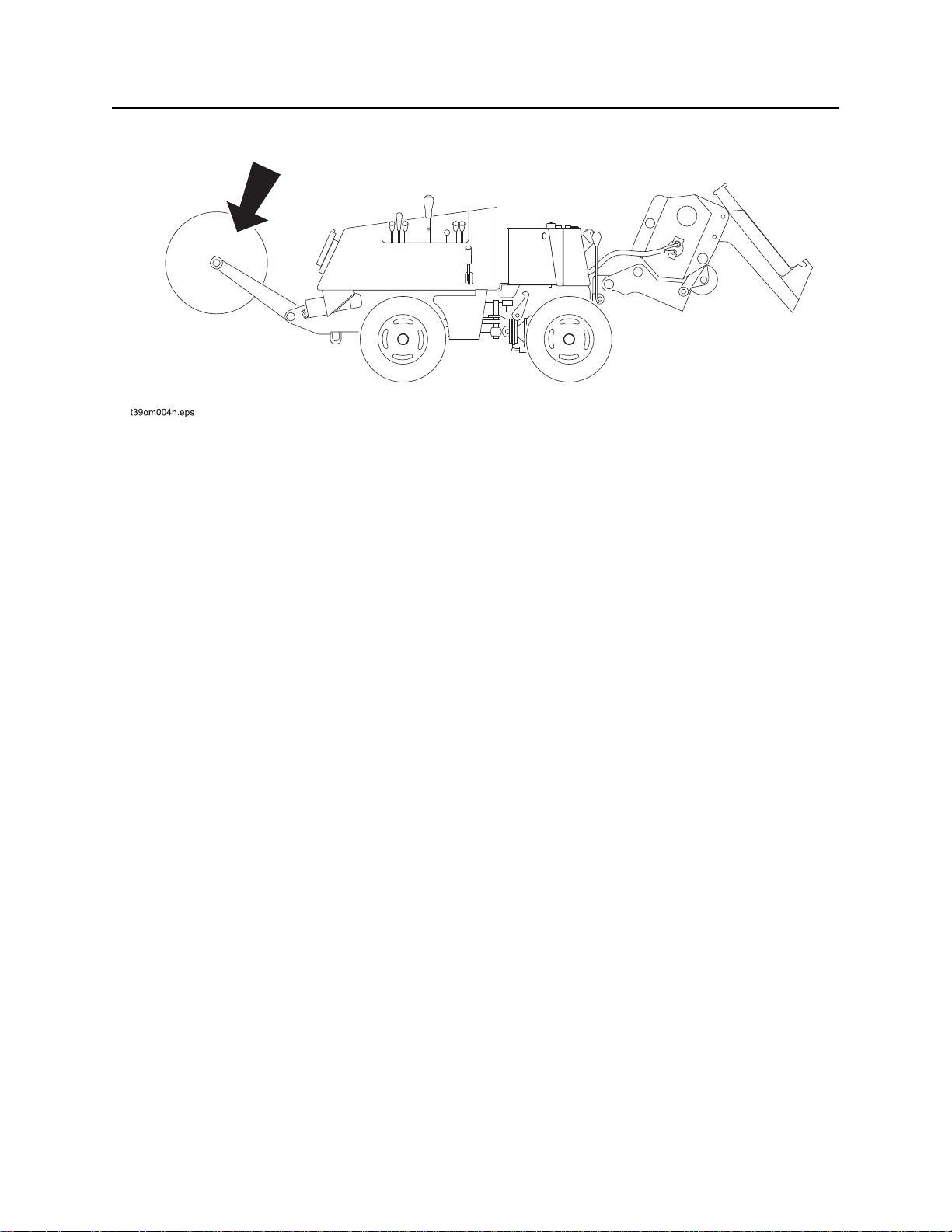
Check Tire Pressures
Check tire pressures before each use.
Tire option Max. pressure
26 x 12.00-12 4-ply bar lug 20 psi (1.4 bar)
DUALS ONLY: 23 x 10.5-12
6-ply bar lug
20 psi (1.4 bar)
t39om004w.eps

410sx Operator’s Manual Service - 89
10 Hour
Check Exhaust Clamp
Check clamp and lock screw on exhaust
extension every 10 hours to ensure that it is tight.
Replace if needed.
t39om061w.eps
Check Engine Coolant Level
Check engine coolant level every 10 hours with
engine cool at plastic overflow tank. Maintain
coolant level above low level mark. If low, add
approved coolant. Clean debris from radiator
cooling fins using compressed air or pressurized
water.
NOTICE:
• Use caution when removing radiator
pressure cap.
• To prevent engine damage or premature
failure, use only approved coolant.
• Do not mix coolant types.
• See “Approved Coolant” on page 84.
Plow
Check Plow Gearbox Oil Level
Check plow vibrator oil level every 10 hours.
Check when oil is cold, with vibrator level and
skid shoes on ground. Remove plow blade and
sod cutter if necessary. Oil should be halfway up
sight glass (2). Add MPL as needed at fill (1).
IMPORTANT: Do not add oil to plow vibrator
when hot. Let plow vibrator cool before
removing fill plug.
t39om063w.eps
12
t39om064w.eps
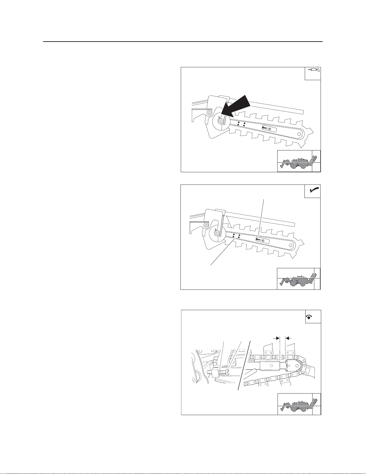
Service - 90 410sx Operator’s Manual
10 Hour
Trencher
Lube Trencher Outboard Auger
Bearing
Wipe zerk clean and lube every 10 hours with 810 pumps of MPG.
t39om006w.eps
Check Digging Chain Tension
2
If unit is equipped with H400 trenching
attachment, check digging chain tension every 10
hours. Distance between chain and boom (4)
should be approximately 1” (25 mm).
To adjust chain with roller boom:
1. Lower boom to ground and stop engine.
2. Engage parking brake.
3. Loosen four trencher clamp bolts (1).
4. Loosen jam nut (2) and turn adjusting screw
78 ft•lb (106 N•m).
To adjust chain with sprocket boom:
1. Lower boom and stop engine.
2. Engage parking brake.
3. Adjust chain tension by tightening or
loosening adjustment screw (2) and jam nut
(1). Digging chain tension is correct when 1-
1.5” (25-40 mm) of slide and stop is exposed
(3).
4. Tighten jam nut.
1
t39om007w.eps
12 3
t39om008w.eps

410sx Operator’s Manual Service - 91
10 Hour
To adjust roller boom with grease cylinder:
Pressurized fluid or air could pierce skin and cause injury or death. Stay
away.
To help avoid injury: Service digging boom grease cylinder only while standing on opposite side of
boom. Wear gloves and safety glasses, and cover fitting with cloth when relieving pressure in cylinder.
1. With boom horizontal, measure distance from
bottom of boom to chain (2). When properly
adjusted, distance should be 1.5-2.0” (40-50
mm).
2. To tighten chain, remove plug and pump MPG
into cylinder (1). To relieve chain tension,
loosen plug on grease cylinder.
1
t39om010w.eps
2
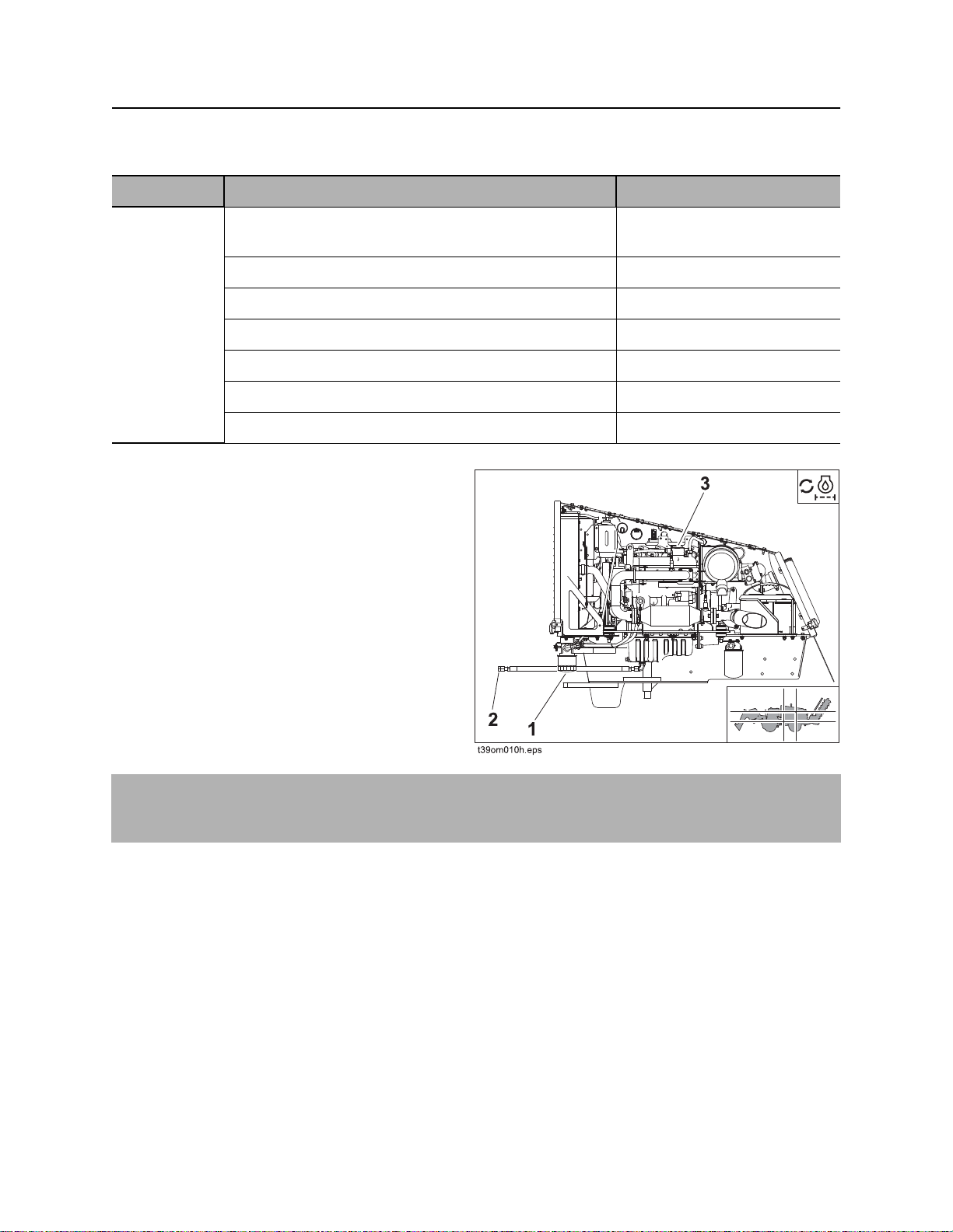
Service - 92 410sx Operator’s Manual
50 Hour
50 Hour
Location Task Notes
TRACTOR Change engine oil and filter GEO, initial service
5.5 qt (5.2 L)
Check fan/alternator belt tension 20 ft•lb (20 N•m)
Check exhaust system
Check radiator hoses
Clean battery terminals
Check air filter dust ejection valve
Check fuel lines
Change Engine Oil and Filter
(Initial Service)
Change engine oil and filter after first 50 hours,
and every 200 hours afterward.
To change:
1. Drain crankcase (1) while oil is warm.
2. Replace filter (2) each time oil is changed.
3. Add GEO at fill neck (3) until oil level is at
highest line on dipstick.
NOTICE: To prevent engine fire, immediately wipe off any oil that drips on the exhaust tubes or thermal
blankets. Replace thermal blankets if oil gets between the blanket and the exhaust system. Do not
operate machine with oil between the blanket and the exhaust system

410sx Operator’s Manual Service - 93
50 Hour
Check Fan/Alternator Belt Tension
Check belt tension every 50 hours. Belt is properly
tensioned when it moves about 0.28 - 0.35” (7-9
mm) when pushed at the long span (A). To adjust
belt, loosen bolt (B) and move tensioner pulley.
Tighten bolt (B) to 20 ft-lb (27 N-m).
t39om011w.eps
Check Exhaust System
B
A
Thermal blankets contain refractory ceramic fibers, which are a possible
carcniogen and will cause irritation when airborne. Wear proper personal protective
equipment, including gloves, safety glasses and breathing protection.
To help avoid injury, place damaged blanket in a plastic bag to prevent material from
becoming airborne during disposal.
Check for any loose or damaged components
every 50 hours. Check exhaust thermal blankets
and replace if damaged. Check heat shields near
the battery, starter and air cleaner and replace if
damaged.
t39om065w.eps

Service - 94 410sx Operator’s Manual
50 Hour
Check Radiator Hoses
Check radiator hoses for leaks, abnormal swelling,
or other signs of deterioration every 50 hours. Also
check for leaks or corrosion at water pump and
fittings.
t39om032w.eps
Clean Battery Terminals
Clean battery terminals to remove any corrosion
and apply MPG to terminals after cleaning to
reduce corrosion. Check for signs of internal
corrosion in cables and tighten any loose
connections.
Check Air Filter Dust Ejection Valve
Check the dust ejection valve on the air filter every
50 hours. Replace if damaged. The valve should
close when the engine is running for proper
operation. Ensure that air filter cover is installed
with valve at the 6 o’clock position.
t39om033w.eps
t39om034w.eps

410sx Operator’s Manual Service - 95
50 Hour
Check Fuel Lines
Check fuel lines for any signs of leaks or wear
every 50 hours. Replace as needed only with low
permeable fuel hose rated at 225 psi (p/n 105-
1792), required for EPA emission regulations.
t39om070w.eps

Service - 96 410sx Operator’s Manual
100 Hour
100 Hour
Location Task Notes
TRACTOR Change fuel filter See engine operator’s
manual for more information
Change Fuel Filter
Change fuel filter (shown) every 100 hours.
t39om037w.eps
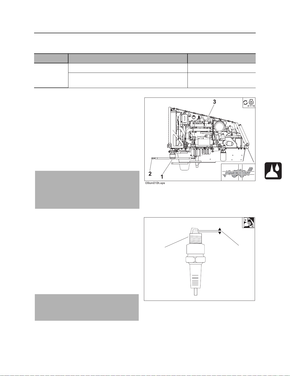
410sx Operator’s Manual Service - 97
200 Hour
200 Hour
Location Task Notes
TRACTOR Change engine oil and filter 5.5 qt (5.2 L) GEO
Clean spark plugs See engine operator’s
manual for more information
Change Engine Oil and Filter
Change engine oil and filter after first 50 hours,
and every 200 hours afterward.
To change:
1. Drain crankcase (1) while oil is warm.
2. Replace filter (2) each time oil is changed.
3. Add GEO at fill neck (3) until oil level is at
highest line on dipstick.
NOTICE: To prevent engine fire, immediately
wipe off any oil that drips on the exhaust tubes
or thermal blankets. Replace thermal blankets
if oil gets between the blanket and the exhaust
system. Do not operate machine with oil
between the blanket and the exhaust system
Clean Spark Plugs and Check Gap
1. Remove the spark plug and remove carbon
from the electrode.
2. Measure the spark plug gap with a feeler
gauge and adjust or replace the spark plug if
the measured gap differs from the factory
specification: 0.028-0.031 in (0.70-0.80 mm)
3. Replace the spark plug if the electrode or the
insulator is deformed or cracked.
4. Tighten the spark plug to 20 ft-lb (27 N-m).
IMPORTANT: When reassembling, install the
ignition coil inside the spark plug terminal
firmly. Make sure that the wiring and the
ignition coil are correctly connected.
12
t39om068w.eps

Service - 98 410sx Operator’s Manual
250 Hour
250 Hour
Location Task Notes
TRACTOR Change hydraulic fluid filters 14 gal (53 L)
Change Hydraulic Fluid Filters
Change hydraulic fluid filters every 250 hours.
Spin-on type filter elements should be handtightened. Do not overtighten. Check oil level at
hydraulic reservoir sight glass and fill with fluid as
needed.
12
t39om035w.eps
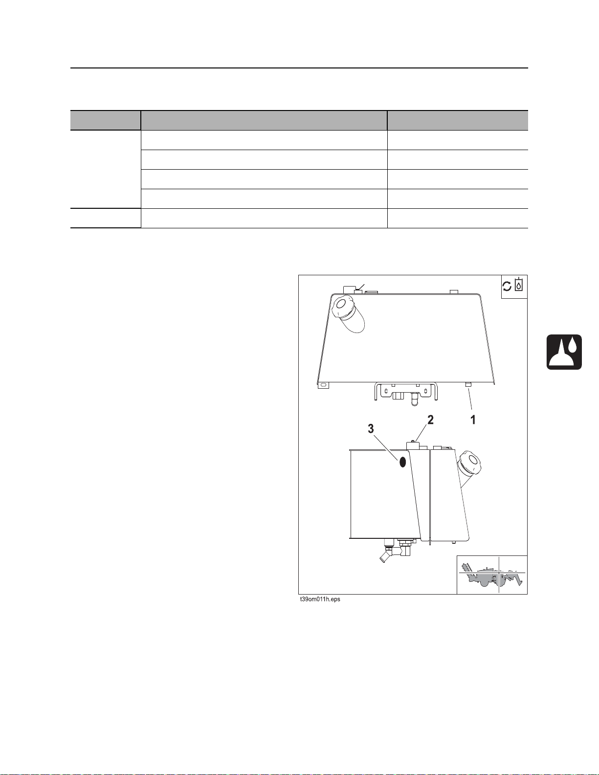
410sx Operator’s Manual Service - 99
500 Hour
500 Hour
Location Task Notes
TRACTOR Change hydraulic fluid and filter 13.2 gal (50 L) THF
Lubricate and inspect u-joints MPG
Check ground drive differential oil level MPL
Check ground drive gearbox oil level MPL
PLOW Change plow vibrator oil 2.4 pt (1 L) MPL
Tractor
Change Hydraulic Fluid and Filters
Change hydraulic fluid and filters every 500 hours.
To change hydraulic fluid:
1. With fluid warm, remove drain plug (1), located
at bottom of reservoir on right side of tractor.
2. Drain fluid and replace plug.
3. Fill through fill cap (2) to center of reservoir
sight glass (3) with THF. Reservoir capacity is
13.2 gal (50 L).
 Loading...