


150R/T
Operator’s
Manual
CMW
®
Issue 1.1
053- 1104

150R/T Operator’s Manual Overview - 1
Overview
Chapter Contents
Serial Number Location . . . . . . . . . . . . . . . . . . . . . . 2
Intended Use . . . . . . . . . . . . . . . . . . . . . . . . . . . . . . . 3
About This Manual . . . . . . . . . . . . . . . . . . . . . . . . . . 3
• Bulleted Lists. . . . . . . . . . . . . . . . . . . . . . . . . . . . . . . . . . . . . . . . . . . . . . .3
• Numbered Lists. . . . . . . . . . . . . . . . . . . . . . . . . . . . . . . . . . . . . . . . . . . . .3
• “Continued” Indicators. . . . . . . . . . . . . . . . . . . . . . . . . . . . . . . . . . . . . . . .3
FCC Statement . . . . . . . . . . . . . . . . . . . . . . . . . . . . . 4
CMW
Overview - 2 150R/T Operator’s Manual
Serial Number Location
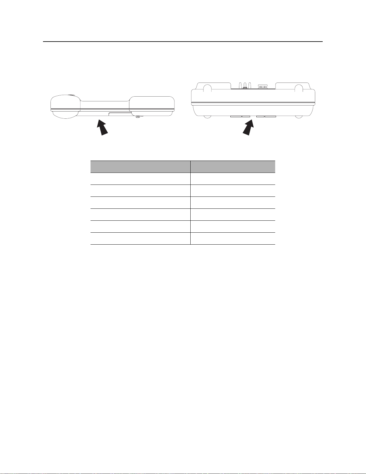
Serial Number Location
Record serial numbers and date of purchase in spaces provided. Unit serial number is located as shown.
Item
date of purchase:
receiver serial number:
transmitter serial number:
accessory model & serial number:
accessory model & serial number:
accessory model & serial number:
CMW

150R/T Operator’s Manual Overview - 3
Intended Use
Intended Use
The system can be configured to locate pipe and cable or trace metallic and non-metallic pipe or conduit.
The 150R receiver is available in peak or null configurations. Unit s con figured to ope rate in the peak mode
will have one active frequency (640Hz, 30kHz or 83kHz) as well as 60S and 60P. Units configured to
operate in null mode will only have one frequency (83kHz).
The 150T transmitter places signals on target lines to be detected by 150R receivers. It is configured to
send 30kHz or 83kHz frequencies. It places a signal on the line through either direct connection, induction
clamping, or broadcast modes.
An optional 150B beacon broadcasts a signal from a metallic pipe, non-metallic pipe or conduit. It is
available in two different frequencies (640Hz, 30kHz). The beacon is attached to a flex rod, placed into a
pipe and tracked with the 150R receiver.
The unit is designed for operation in temperatures typically experienced in earth moving and construction
work environments. Use in any other way is considered contrary to the intended use. The 150 system
should be operated only by persons familiar with its particular characteristics and acquainted with the
relevant safety procedures. The system should be serviced only by Ditch Witch repair centers.
About This Manual
This manual contains information for the proper use of this equipment. Cross references such as “See
page 50” will direct you to det ailed procedures.
Bulleted Lists
Bulleted lists provide helpful or important information or contain procedures that do not have to be
performed in a specific order.
Numbered Lists
Numbered lists contain illustration callouts or list steps that must be performed in order.
“Continued” Indicators
indicates that a procedure is continued on the next page.
CMW

Overview - 4 150R/T Operator’s Manual
FCC Statement
FCC Statement
This device complies with Part 15 of the FCC Rules. Operation is subject to the following two conditions:
(1) this device may not cause harmful interference, and (2) this device must accept any interference
received, including interference that may cause undesired operation.
Changes or modifications not expressly approved by The Charles Machine Works, Inc. could void the
user’s authority to operate the equipment.
This equipment has been tested and found to comply with the limits for a Class A digital device, pursuant
to Part 15 of the FCC Rules. These limits are designed to provide reasonable protection against harmful
interference when the equipment is operated in a commercial environment. This equipment generates,
uses, and can radiate radio frequency energy and, if not installed and used in accordance with the
operator’s manual, may cause harmful interference to radio communications. Operation of this equipment
in a residential area is likely to cause harmful interference in which case the user will be required to correct
the interference at his own expense.
CMW

150R/T Operator’s Manual Foreword - 5
Foreword
This manual is an important part of your equipment. It provides safety information and operation
instructions to help you use and maintain your Ditch Witch equipment.
Read this manual before using your equipment. Keep it with the equipmen t at all times for future reference.
If you sell your equipment, be sure to give this manual to the new owner.
If you need a replacement copy, contact your Ditch Witch. If you need assistance in locating a dealer, visit
our website at www.ditchwitch.com or write to the following address:
The Charles Machine Works, Inc.
Attn: Marketing Department
PO Box 66
Perry, OK 73077-0066
USA
The descriptions and specifications in this manual are subject to change without notice. The Charles
Machine Works, Inc. reserves the right to improve equipment. Some product improvements may have
taken place after this manual was publishe d. For the latest information on Ditch Witch equipment, see your
Ditch Witch dealer.
Thank you for buying and using Ditch Witch equipment.
CMW

Foreword - 6 150R/T Operator’s Manual
150R/T
Operator’s Manual
Issue number 1.1/OM-5/07
Part number 053-1104
Copyright 2006, 2007
by The Charles Machine Works, Inc.
, Ditch Witch, CMW, AutoCrowd, Modularmatic, Jet Trac, Roto Witch, Subsite,
Fluid Miser, Perma-Soil, Power Pipe, Super Witch, Super Witch II, Pierce Airrow, The Underground, and
The Underground Authority Worldwide are r egistered trademarks of The Charles Machine Works, In c.
CMW

150R/T Operator’s Manual Contents - 7
Contents
Overview
machine serial number, information about the type of work this machine is designed
to perform, basic machine components, and how to use this manual
Foreword
part number, revision level, and publication date of this manual, and factory contact
information
Safety
machine safety alerts and emergency procedures
Controls
machine controls and how to use them
Locate
procedures for locating active, passive and beacon signals
Locating Concepts
basic information for locating active, passive and beacon signals
Service
service intervals and instructions for this machine
1
5
9
13
25
39
43
Specifications
machine specifications including weights, measurements and power rating
Support
the warranty policy for this machine, and procedures for obtaining warranty
consideration and training
47
51
CMW

Contents - 8 150R/T Operator’s Manual
CMW

150R/T Operator’s Manual Safety - 9
Safety
Chapter Contents
Guidelines . . . . . . . . . . . . . . . . . . . . . . . . . . . . . . . . 10
Safety Alert Classifications . . . . . . . . . . . . . . . . . . 11
Safety Alerts . . . . . . . . . . . . . . . . . . . . . . . . . . . . . . 12
CMW

Safety - 10 150R/T Operator’s Manual
Guidelines
Guidelines
Follow these guidelines before operating any jobsite equipment:
• Complete proper training and read operator’s manual before using equipment.
• Classify jobsite based on its hazards and use correct tools and machin ery, safety equipment, and work
methods for jobsite.
• Mark jobsite clearly and keep spectators away.
• Wear personal protective equipment.
• Review jobsite hazards, safety and emergency procedures, and individual responsibilities with all
personnel before work begins.
• Replace missing or damaged safety signs.
• Use equipment carefully. Stop operation and investigate anything that does not look or feel right.
• Contact your equipment dealer if you have any question about operation, maintenance, or equipment
use.
CMW

150R/T Operator’s Manual Safety - 11
Safety Alert Classifications
Safety Alert Classifications
These classifications and the icons defined on the following pages work together to alert you to situations
which could be harmful to you, jobsite bystanders or your equipment. When you see these words and
icons in the book or on the unit, carefully read and follow all instructions. YOUR SAFETY IS AT STAKE.
Watch for the three safety alert levels: DANGER, WARNING and CAUTION. Learn what each level
means.
indicates an imminently hazardous situation which, if not avoided, will result in death or
serious injury.
indicates a potentially hazardous situation which, if not avoided, could result in death or
serious injury.
indicates a potentially hazardous situation which, if not avoided, may result in minor or
moderate injury.
Watch for two other words: NOTICE and IMPORTANT.
NOTICE can keep you from doing something that might damage the unit or someone's property. It can also
alert you against unsafe practices.
IMPORTANT can help you do a better job or make your job easier in some way.
CMW
Safety - 12 150R/T Operator’s Manual
Safety Alerts
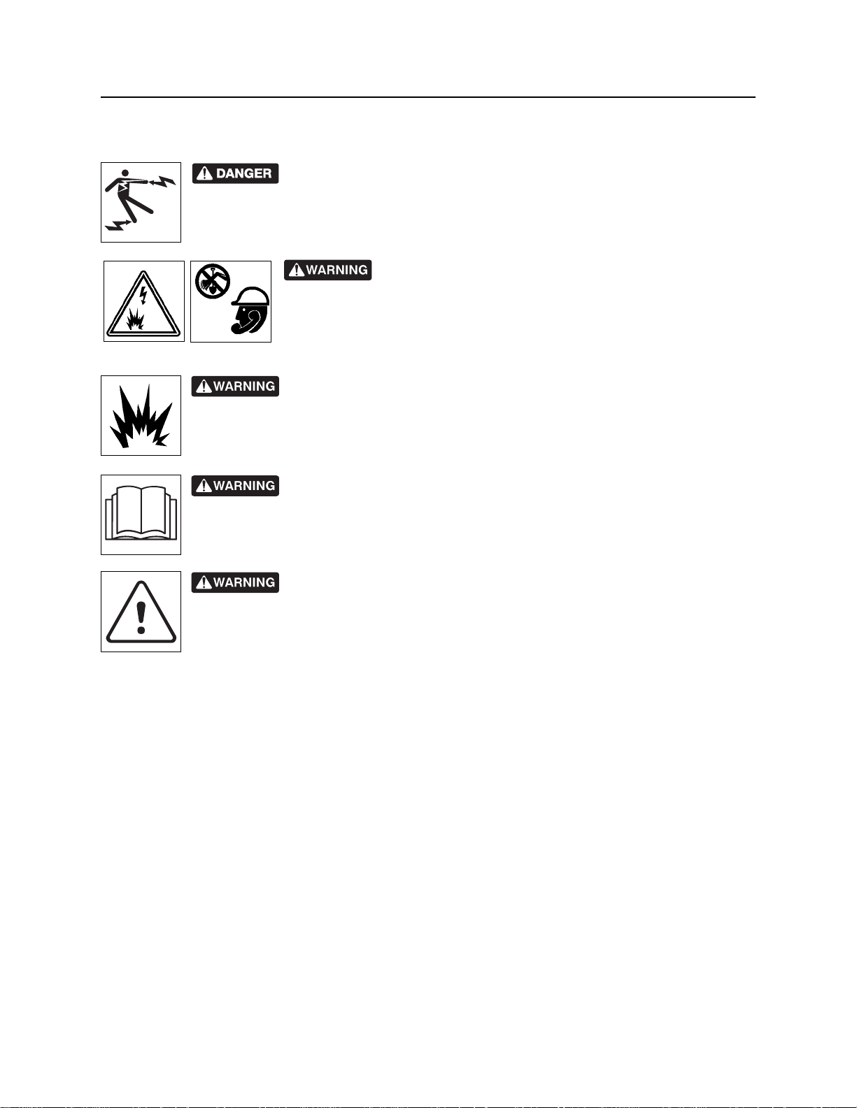
Safety Alerts
Electric shock. Contacting electric lines will cause death or serious injury.
Know location of lines and stay away.
Jobsite hazards could cause death or serious injury. Use
correct equipment and work methods. Use and maintain proper safety
equipment.
Explosion possible. Serious injury or equipment damage could occur.
Follow directions carefully.
Incorrect procedures could result in death, injury, or property damage.
Learn to use equipment correctly.
Moving traffic - hazardous situation. Death or serious injury could result.
Avoid moving vehicles, wear high visibility clothing, post appropriate warning signs.
CMW

150R/T Operator’s Manual Controls - 13
Controls
Chapter Contents
Receiver. . . . . . . . . . . . . . . . . . . . . . . . . . . . . . . . . . 14
• Controls. . . . . . . . . . . . . . . . . . . . . . . . . . . . . . . . . . . . . . . . . . . . . . . . . .14
• Displays. . . . . . . . . . . . . . . . . . . . . . . . . . . . . . . . . . . . . . . . . . . . . . . . . .16
• Menu. . . . . . . . . . . . . . . . . . . . . . . . . . . . . . . . . . . . . . . . . . . . . . . . . . . .19
Transmitter . . . . . . . . . . . . . . . . . . . . . . . . . . . . . . . 23
CMW
Controls - 14 150R/T Operator’s Manual
Receiver
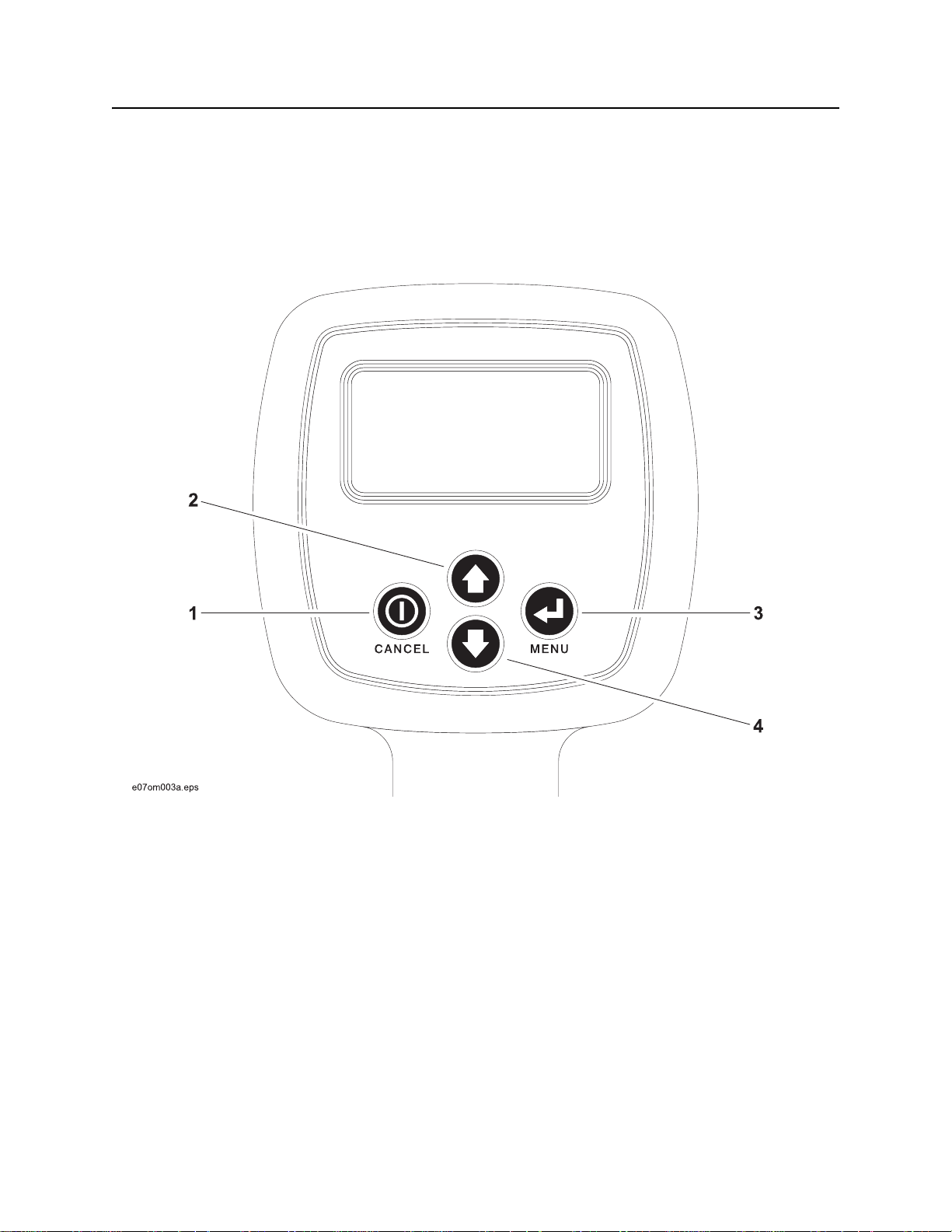
Receiver
Controls
1. On-off/Cancel
2. Up arrow
CMW
3. Select/Menu
4. Down arrow
150R/T Operator’s Manual Controls - 15
Receiver
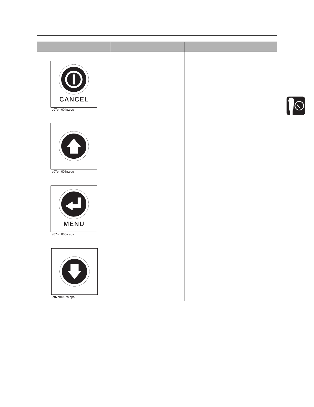
Item Description Notes
1. On-Off/Cancel To turn on, press.
To turn off, press again.
To cancel current action in
menu mode, press.
2. Up Arrow To increase gain, press.
To scroll up menu options in
menu mode, press.
3. Select/Menu To access the menu screen,
press.
To select highlighted menu
option, press again.
4. Down Arrow To decrease gain, press.
To scroll down menu options
in menu mode, press.
CMW
Controls - 16 150R/T Operator’s Manual
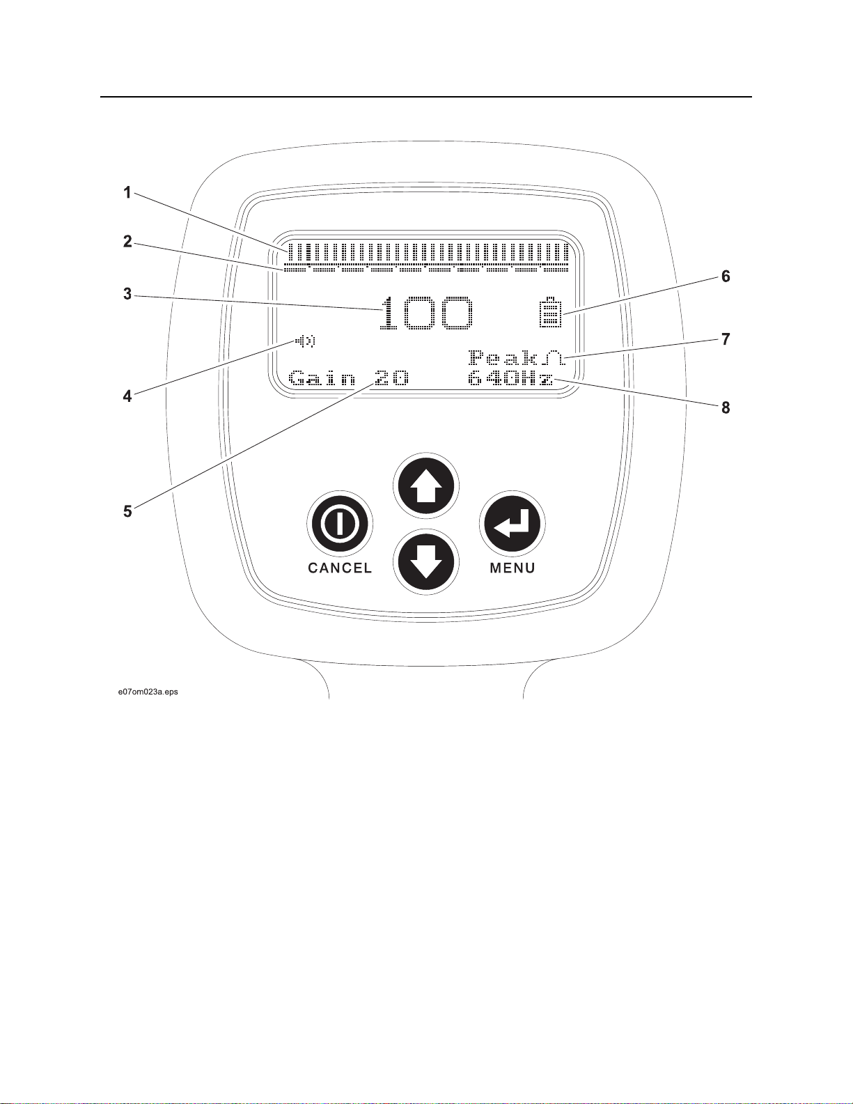
Receiver
Displays
1. Signal bar
2. Gain bar
3. Signal strength
4. Volume level
CMW
5. Gain level
6. Battery level
7. Antenna mode
8. Frequency

150R/T Operator’s Manual Controls - 17
Receiver
Item Description Notes
1. Signal Bar Graphically represents the
signal strength levels.
2. Gain Bar Graphically represents the
gain.
Gain increases to the right.
3. Signal Strength Numerically represents the
one-hundred and one (0-100)
signal strength levels.
4. Volume Level Indicates volume is turned to
an on position.
5. Gain Level Numerically represents
twenty-one (0-20) gain levels.
CMW

Controls - 18 150R/T Operator’s Manual
Receiver
Item Description Notes
6. Battery Level Indicates battery level. Three
segments indicates full
battery level. One segment
indicates low level. No
segments indicates that
batteries should be changed
soon.
7. Antenna Mode Indicates factory antenna
configuration. Unit is factory
configured in peak or null
mode.
8. Frequency Indicates frequency setting.
CMW

150R/T Operator’s Manual Controls - 19
Receiver
Menu
Select Frequency (Peak Units)
IMPORTANT: Receiver units configured to
operate in null mode do not have a frequency
menu.
The 150R has three available active and two
passive frequencies: 640Hz, 30kHz, or 83kHz,
60S, and 60P.
1. Press Menu to select frequency setting.
2. Press Menu to select the Frequency option.
3. Use Up Arrow or Down Arrow to highlight
the desired frequency.
IMPORTANT: 150R units will be factory
configured with either 640Hz, 30kHz or
83kHz.
4. Press Menu to return to display.
Adjust Volume
Receiver has four volume levels: off, low , medium
and high.
1. Press Menu to select volume setting.
2. Press Down Arrow to highlight volume
option.
3. Press Menu to select the volume menu.
CMW

Controls - 20 150R/T Operator’s Manual
Receiver
4. Use Up Arrow or Down Arrow to adjust the
volume to the desired level.
5. Press Menu to return to display.
IMPORTANT: Maintain a lower volume to
conserve battery life.
Setup Menu
Setup Menu allows operator to select audio mode,
adjust contrast and perform a self test.
1. Press Menu to enter setup menu.
2. Press Down Arrow to highlight setup.
3. Press Menu to select Setup.
Select Audio Mode
Receiver has two audio modes: single tone
(volume increases with signal strength) and tone
shift (pitch increases with signal strength).
1. Enter Setup Menu, see “Setup Menu” on
page 20.
2. Select Audio Mode menu, press Menu.
3. Use the Up Arrow or the Down Arrow to
select the desired audio mode.
4. Press Menu to return to display.
CMW

150R/T Operator’s Manual Controls - 21
Receiver
Adjust Contrast
Receiver has twenty-five levels of contrast from
light to dark.
1. Enter Setup Menu, See “Setup Menu” on
page 20.
2. Press Down Arrow to highlight Contrast.
3. Press Menu to enter Contrast menu.
4. Use Up Arrow or Down Arrow to adjust
contrast to desired level.
5. Press Menu to return to display.
CMW

Controls - 22 150R/T Operator’s Manual
Receiver
Perform Self Test
Receiver performs self test to detect errors.
1. Enter Setup Menu, see “Setup Menu” on
page 20.
2. Press Down Arrow to highlight Self Test.
3. Press Menu to perform a self test.
4. Turn off all beacons and transmitters.
5. Press any key to begin test.
IMPORTANT: Do not move receiver during test.
6. Receiver will display self test results.
• If receiver finds no errors, it will display “All channels passed. Press any key . . . .”
• If receiver detects errors the operator can resolve, see “Receiver Error Messages” on page 46.
CMW

150R/T Operator’s Manual Controls - 23
Transmitter
Transmitter
1. Power 2. Battery level indicator
Item Description Notes
1. Power To deliver high power, move
switch up.
To deliver low power, move
switch down.
To turn off, move switch to
center.
CMW

Controls - 24 150R/T Operator’s Manual
Transmitter
Item Description Notes
2. Battery Level Indicator Indicates battery level when
unit is in high or low position.
• Solid light indicates
sufficient battery level.
• Flashing light during
operation indicates low
battery level.
• Flashing light at startup
indicates battery level is
low or one battery is
installed backwards.
IMPORTANT:
• The unit will continue transmitting
a signal if green light flashes while
in operation but power will
decrease.
• The unit will not transmit a signal
if green light is flashing when unit
is turned on.
CMW

150R/T Operator’s Manual Locate - 25
Locate
Chapter Contents
Active . . . . . . . . . . . . . . . . . . . . . . . . . . . . . . . . . . . 26
• Setup. . . . . . . . . . . . . . . . . . . . . . . . . . . . . . . . . . . . . . . . . . . . . . . . . . . .26
• Technique . . . . . . . . . . . . . . . . . . . . . . . . . . . . . . . . . . . . . . . . . . . . . . . .29
• Special Situations . . . . . . . . . . . . . . . . . . . . . . . . . . . . . . . . . . . . . . . . . .31
Passive . . . . . . . . . . . . . . . . . . . . . . . . . . . . . . . . . . 32
• Setup. . . . . . . . . . . . . . . . . . . . . . . . . . . . . . . . . . . . . . . . . . . . . . . . . . . .32
• Technique . . . . . . . . . . . . . . . . . . . . . . . . . . . . . . . . . . . . . . . . . . . . . . . .32
• Special Situations . . . . . . . . . . . . . . . . . . . . . . . . . . . . . . . . . . . . . . . . . .36
Beacon . . . . . . . . . . . . . . . . . . . . . . . . . . . . . . . . . . 37
• Setup. . . . . . . . . . . . . . . . . . . . . . . . . . . . . . . . . . . . . . . . . . . . . . . . . . . .37
• Technique . . . . . . . . . . . . . . . . . . . . . . . . . . . . . . . . . . . . . . . . . . . . . . . .37
CMW

Locate - 26 150R/T Operator’s Manual
Active Location
Active Location
Setup
Follow setup procedures for the type of locating you will be doing: direct connection, induction clamp, or
broadcast induction. Always check receiver battery level at startup. See “Controls” on page 13.
Direct Connection
Jobsite hazards could cause death or serious injury. Use
correct equipment and work methods. Use and maintain proper safety
equipment.
NOTICE: Electric shock or equipment damage can result if transmitter is connected to live cable.
Contact qualified utility personnel and follow all standards and requirements for disconnecting and
grounding lines.
To set up transmitter for direct connection:
1. Drive ground stake (4).
2. Plug cable into transmitter (2).
3. Hook black lead to ground stake (3).
4. Hook red lead to line (1).
5. Turn on transmitter.
6. Check battery level indicator.
NOTICE:
• Do not unplug direct connect cable
from transmitter when connected to
line. Removing cable will cause an
arc and could damage equipment
or cause injury.
• Turn off transmitter when
connecting or moving ground
stake.
CMW

150R/T Operator’s Manual Locate - 27
Active Location
Induction Clamp
Jobsite hazards could cause death or serious injury. Use
correct equipment and work methods. Use and maintain proper safety
equipment.
NOTICE: Electric shock or equipment damage can result if transmitter is connected to live cable.
Contact qualified utility personnel and follow all standards and requirements for disconnecting and
grounding lines.
To set up transmitter for use with induction
clamp:
1. Plug cable into transmitter (1).
2. Place clamp around line (2).
3. Turn on transmitter.
4. Check battery level indicator.
NOTICE: Do not unplug induction
cable from transmitter (1) when
connected to line (2). Removing cable
will cause an arc and could damage
equipment or cause injury.
CMW

Locate - 28 150R/T Operator’s Manual
Active Location
Broadcast Induction
To set up transmitter for broadcast induction:
1. Remove cable, stake, clamp and any other
metal objects from transmitter.
2. Place transmitter parallel to and directly
above suspected line as shown.
Note: Transmitter must be parallel to
object, as shown, in order to produce
the best signal.
3. Turn on transmitter.
4. Check battery level indicator.
CMW

150R/T Operator’s Manual Locate - 29
Active Location
Technique
IMPORTANT: Follow steps 1-3 for all types of active location. For reference, the illustration above
shows direct connection method. If using broadcast ind uction, ensure that tr ansm itter is in line with and
above suspected line, as shown on previous page.
1. Walk in an arc approximately 25’ (7.5 m) around utility to be located.
2. Hold the receiver so that the handle points toward the transmitter, as shown.
3. Identify location of line by finding the spot with the best signal response.
CMW

Locate - 30 150R/T Operator’s Manual
Active Location
4. Rotate the receiver to determine which
direction the line runs.
IMPORTANT: Receiver indicates the
best signal when the handle lines up
with the target line.
5. Trace the line and mark with appropriate
flags or paint.
CMW

150R/T Operator’s Manual Locate - 31
Active Location
Mark the Line
Sweep, focus, and trace all detected signals in the area. Mark line paths with colored paint or flags. See
the chart below for standard color markings for line locations.
Utility Color Marking Symbol
electric red -Egas/oil yellow -Gcommunications orange -TEL- or -TVwater blue -Wsewer green -S-
Special Situations
Situation What to try
Signal is lost. Walk in a circle to detect a tee or bend in the line.
Signal varies from low to high and is
unstable.
You are near a power line and are
receiving interference.
Receiver does not function properly. Receiver gain could be set too high or low. Lower or raise
Target line has connections to other lines. Disconnect target line from other lines or use direct
Signal is transferring to other lines. • Lower the power level.
Mark as a hand-dig area.
Sweep the area in 60P mode. If receiver gives a strong
signal response, a power line is interfering with transmitter
signal.
gain to locate the line. See “Controls” on page 13.
connect or induction clamp to focus signal on target line.
• Use direct connection, if possible, or use induction
clamp.
• Move the ground stake away from the target line and
away from other buried lines.
• Apply signal at the point where the target line is
farthest from the other lines.
CMW

Locate - 32 150R/T Operator’s Manual
Passive Location
Passive Location
Setup
Follow setup procedures for the type of locating you will be doing. Always check receiver battery level at
startup. See “Controls” on page 13.
NOTICE: Lines with no AC current flowing through them are hard to detect and may be hazardous
because they may still have voltage potential. To locate, turn on an appliance to cause current to flow
and use active search methods.
Use 60P frequency to locate primary lines from source to transformer. Use 60S frequency to locate
secondary lines from transformer to meter.
Technique
Survey the Site
Make a visual check of the site for signs of buried lines such as:
• recent trenching
• buried line markers
• overhead lines that run down pole and underground
• gas meters
• valve sights
• drains or manhole covers
CMW

150R/T Operator’s Manual Locate - 33
Passive Location
Sweep the Site
Search the site by walking a grid pattern while
holding receiver close to the ground.
NOTICE: Keep receiver level.
Focus the Signal
Move receiver over detected signal to find best signal response. If using a peak antenna mode, rotate
receiver until signal is best. Best signal indicates line direction.
NOTICE: Keep receiver level.
CMW

Locate - 34 150R/T Operator’s Manual
Passive Location
Antenna Mode Configuration
All 150R receiver units can locate in either peak or null mode.
Rotate receiver 90° to locate using other antenna
mode. When rotated 90°, a peak configured
receiver will function as a null receiver or a null
configured receiver will function as a peak
receiver.
IMPORTANT: The operator will not be able to
view display in other antenna mode.
CMW

150R/T Operator’s Manual Locate - 35
Passive Location
Trace the Line
Walk along the suspected path while moving
the receiver from side to side across the area.
IMPORTANT: Keep receiver handle parallel
to the suspected line path.
CMW

Locate - 36 150R/T Operator’s Manual
Passive Location
Mark the Line
Sweep, focus, and trace all detected signals in the area. Mark line paths with colored paint or flags. See
the chart below for standard color markings for line locations.
Utility Color Marking Symbol
electric red -E-
Special Situations
Situation What to try
Signal is lost. Walk in a circle to detect a tee or bend in the line.
Signal varies from low to high and is
unstable.
Receiver does not function properly. Receiver gain could be set too high or low. Lower or raise
Mark as a hand-dig area.
gain to locate the line. See “Controls” on page 13.
CMW

150R/T Operator’s Manual Locate - 37
Beacon Location
Beacon Location
Trace metallic or non-metallic pipes or conduits by locating and following a beacon signal.
IMPORTANT: Large metal objects and other signals (such as railroad signals or overhead power lines)
will distort signal.
Setup
To set up for beacon location:
1. Follow instructions for installing beacon battery.
2. Turn on receiver to ensure that beacon is functioning properly.
3. Attach beacon to plumber’s snake or flex rod.
Technique
1. Turn on receiver.
2. Set signal frequency.
3. Place beacon into the pipe and move it
down the pipe.
4. To locate beaco n, circ le ov er its
approximate location in the pipe.
5. To identify the location of beacon, find the
spot with the strongest signal response.
6. Rotate the receiver to determine which
direction beacon runs.
IMPORTANT: Receiver indicates the
best signal when handle is
perpendicular to the beacon.
7. Continue to track beacon. Mark pipe
location with paint.
CMW

Locate - 38 150R/T Operator’s Manual
Beacon Location
CMW

150R/T Operator’s Manual Locating Concepts - 39
Locating Concept s
Chapter Contents
Signal Type . . . . . . . . . . . . . . . . . . . . . . . . . . . . . . . 40
• Active . . . . . . . . . . . . . . . . . . . . . . . . . . . . . . . . . . . . . . . . . . . . . . . . . . .40
• Beacon . . . . . . . . . . . . . . . . . . . . . . . . . . . . . . . . . . . . . . . . . . . . . . . . . .40
• Passive . . . . . . . . . . . . . . . . . . . . . . . . . . . . . . . . . . . . . . . . . . . . . . . . . .40
Antenna Configuration . . . . . . . . . . . . . . . . . . . . . 41
• Peak . . . . . . . . . . . . . . . . . . . . . . . . . . . . . . . . . . . . . . . . . . . . . . . . . . . .41
• Null . . . . . . . . . . . . . . . . . . . . . . . . . . . . . . . . . . . . . . . . . . . . . . . . . . . . .41
• Advantages/Disadvantages . . . . . . . . . . . . . . . . . . . . . . . . . . . . . . . . . .41
Common Signal Problems . . . . . . . . . . . . . . . . . . . 42
• Shadows . . . . . . . . . . . . . . . . . . . . . . . . . . . . . . . . . . . . . . . . . . . . . . . . .42
• False Signals. . . . . . . . . . . . . . . . . . . . . . . . . . . . . . . . . . . . . . . . . . . . . .42
• Secondary (Ghost) Signals. . . . . . . . . . . . . . . . . . . . . . . . . . . . . . . . . . .42
CMW

Locating Concepts - 40 150R/T Operator’s Manual
Signal Type
Signal Type
The 150R can detect three types of signals:
• Active signals that are placed on a target line with a transmitter.
• An active signal from a beacon.
• Passive signals that reside on the target line.
Active
There are three ways to place active signals on a target line with a transmitter:
• Direct connection (preferred method) requires a connection to be made directly onto target line.
• Induction requires placing an optional induction clamp around target line.
• Broadcast method uses a built-in antenna to broad cast a signal onto lines near the transmitter.
Beacon
Beacon signals allow metallic and non-metallic pipe or conduit tracing.
Passive
Power line signals can be detected passively without a transmitter.
Receiver Gain Level
The receiver gain setting controls the sensitivity to the signal.
Action Result Effect
increasing gain more sensitive to signal allows location farther away from
signal source
decreasing gain less sensitive to signal stabilizes signal
CMW

150R/T Operator’s Manual Locating Concepts - 41
Antenna Configuration
Antenna Configuration
The 150R receiver is available with one of two antenna configurations: peak or null.
Peak
Uses a horizontal antenna to detect signal. Response is highest at strongest signal.
Null
Uses a vertical antenna to detect signal. Search width is narrower than peak. Response is lowest when
receiver is over the line.
Advantages/Disadvantages
Read the descriptions below and determine th e antenna configuration that best fits your job.
Antenna Antenna Advantages Disadvantages
peak more range less precise
null sharp response easily distorted in
congested areas
CMW

Locating Concepts - 42 150R/T Operator’s Manual
Common Signal Problems
Common Signal Problems
Distortions in the electromagnetic field around a line can affect location accuracy. Tees, bends, parallel
lines, crossing lines, or large metallic objects can distort signals.
IMPORTANT: If target depth and location are critical, confirm by hand-digging or vacuum excavation.
Learn to recognize the following kinds of distortion:
Shadows
Shadows, also called blind spots, often happen when a metallic object partially obstructs the signal, or a
signal from a parallel line interferes with target signal.
False Signals
False signals describe situations where the receiver indicates a line location where there is no line. False
signals often happen when a line tees or bends, runs parallel to the target line, or crosses the target line.
IMPORTANT: Generally, the receiver shows less distortion in peak antenna configuration.
Secondary (Ghost) Signals
A typical beacon signal pattern shows a main signal and two weaker secondary signals. Identify beacon
location at the main signal. Familiarity with beacon signal patterns will lessen the effect of ghost signals.
CMW

150R/T Operator’s Manual Service - 43
Service
Chapter Contents
General Care . . . . . . . . . . . . . . . . . . . . . . . . . . . . . . 44
As Needed . . . . . . . . . . . . . . . . . . . . . . . . . . . . . . . . 44
Self Test Error Messages . . . . . . . . . . . . . . . . . . . . 46
Receiver Error Messages. . . . . . . . . . . . . . . . . . . . 46
CMW

Service - 44 150R/T Operator’s Manual
General Care
General Care
Under normal operating conditions, receiver and transmitter need only minor maintenance . Following
these care instructions can ensure longer equipment life:
• Do not drop the equipment.
• Do not expose the equipment to high heat (such as in the rear window of a vehicle).
• Clean equipment with a damp cloth and mild soap. Never use scouring powder.
• Do not immerse in any liquid.
• Inspect housing daily for cracks or other damage. If housing is damaged, contact your equipment
dealer for replacement.
• Do not mix new and used batteries.
As Needed
Location Task Notes
Receiver Unit Change batteries 2 “C” batteries
Transmitter Unit Change batteries 6 “C” batteries
Receiver Unit
Change Batteries
Use two C-cell alkaline batteries in receiver.
1. Remove battery cover.
2. Insert batteries as shown.
3. Install and tighten battery cover.
4. Check operation.
CMW

150R/T Operator’s Manual Service - 45
As Needed
Transmitter Unit
Change Batteries
Use six C-cell alkaline batteries in transmitter.
1. Open battery cover.
2. Insert batteries as shown.
IMPORTANT: Do not mix new and
used batteries.
3. Close and tighten battery cover.
4. Check operation. If battery light is flashing
when unit is turned on, then one battery is
incorrectly installed or batteries are weak.
CMW

Service - 46 150R/T Operator’s Manual
Self Test Error Messages
Self Test Error Messages
A receiver self test may return an error message for four reasons: low sensitivity, a failed channel, noise
present, or gain test failure.
Low Sensitivity
A low sensitivity message will always appear together with a “noise” screen. This could indicate a problem
with the antenna, or it could simply be the result of attempting to test in a noisy environment. Try the test
again later, preferably in a d if ferent location. If this problem per sists, cont act Produ ct Support. A unit in this
condition will still be usable in many cases, but performance will not be optimal.
Noise Present
A noise present message appears with each low sensitivity message. If noise present appears by itself,
the signal received in the test was higher than expected. This is usually the result of noise in the area and
may not indicate a problem. The most likely cause of this message is a transmitter or beacon nearby.
Ensure that all beacons and transmitters are turned off and conduct the test again.
Gain Test Failed
A failed gain test message indicates a specific type of hardware fai lure. Like the other tests, it could result
if there is excessive noise in the area. If the message persists, contact Product Support.
Channel Failed
A failed channel test message indicates that no signal was received by that channel during the test. This
almost always indicates a hardware problem. Contact Product Support.
Receiver Error Messages
Shut Down Failed
A failed shut down message indicates a hardware problem. Remove batteries and contact Product
Support.
CMW

150R/T Operator’s Manual Specifications - 47
150 Receiver
Specifications
150 Receiver
Dimensions U.S. Metric
H Height 2.37” 6.02 cm
L Length 12” 30.48 cm
W Width 4.37” 1 1.01 cm
Weight 2 lb 0.91 kg
CMW

Specifications - 48 150R/T Operator’s Manual
150 Transmitter
150 Transmitter
Dimensions U.S. Metric
H Height 3.43” 8.71 cm
L Length 12” 30.48 cm
W Width 6.25” 15.88 cm
Weight 3 lb 1.36 kg
CMW

150R/T Operator’s Manual Specifications - 49
System Operation
System Operation
Operation U.S. Metric
Operating temperature range -4° F to122° F -20° C to 50° C
Antenna configurations peak, null
Audio output speaker
Operating modes (some optional)
Active line 30kHz, 83kHz
Passive line 60Hz (60P), 180Hz (60S)
Beacon 640Hz, 30kHz
Depth Estimate Tolerances*
150 beacon (640H) in air 12’ 3.66 m
150 beacon (640H) in cast iron 6’ 1.83 m
150 (30k) beacon in air 12’ 3.66 m
30k active (direct connect) 15’ 4.57 m
83k active (direct connect) 15’ 4.57 m
* Locators are calibrated to these tolerances under ideal test field conditions. Actual operating field
conditions may have signal distortions or may contain noise sources which result in depth range that is
less than specified.
CMW

Specifications - 50 150R/T Operator’s Manual
System Operation
CMW

150R/T Operator’s Manual Support - 51
Procedure
Support
Procedure
Notify your dealer immediately of any malfunction or failure of Ditch Witch equipment.
Always give model, serial number, and approximate date of your equipment purchase. This information
should be recorded and placed on file by the owner at the time of purchase.
Return damaged unit to dealer for inspection and warranty consideration if in warranty time frame.
All repairs must be done by an authorized Ditch Witch repair facility. Repairs done elsewhere will void
warranty consideration.
Resources
Publications
Contact your Ditch Witch dealer for publication s and videos covering safety, operation, service, and repair
of your equipment.
Training
For information about on-site, individualized training, contact your Ditch Witch dealer.
CMW

Warranty - 52 150R/T Operator’s Manual
Limited Product Warranty Policy
Warranty
Limited Product Warranty Policy
Warranty Periods
New Product
A twelve-month period starts on the date of delivery to the end user:
trackers, remote displays, receivers, transmitters, radars, fault finders
A six-month period starts on the date of delivery to the end user:
directional and locate beacons
A three-month period starts on the date of delivery to the end user:
accessories: cables, clamps, canoes, bags, and adapters
Used Product (Cosmetics)
A three-month warranty starts on the date of delivery to the end user on use d and refurbished products
sold from Ditch Witch Electronics dealers. Used products are non-returnable.
Service and Repair
A one-month warranty on labor st art s on the date th e unit is repai red, and a three -month warranty o n parts
starts on the date the unit is repaired for all products.
Extended Warranty
The extended warranty may be purchased at the time the equipment is sold or anytime within the original
warranty period. The extension is for an additional twelve or twenty-four months, for a total coverage of
twenty-four to thirty-six months. Exclusions: All beacons and accessories.
CMW

150R/T Operator’s Manual Warranty - 53
Limited Product Warranty Policy
Details and Exclusions
• The warranty includes only Ditch Witch Electronics products and accessories that are manufactured
and distributed by Ditch Witch Electronics. The warranty compensates on defects in material or
workmanship.
• Defects will be determined through inspection by Ditch Witch Electronics or authorized repair centers.
Original purchaser must make the defective item available for inspection within 30 days of the date the
part fails.
• The warranty is limited to replacement of the defective part. The replacement part may be new or
remanufactured. Repair and installation of defective part will be at no charge when product or item is
delivered to Ditch Witch Electronics or an authorized repair center . The product or item will be returned
at no charge for return freight.
• The warranty periods do not represent the useful life of Ditch Witch Electronics products and
accessories.
• If Ditch Witch Electronics products are purchased for commercial purposes, as defined by the
Commercial Code, no warranties extend beyond the specific terms set forth in this limited warranty. All
other provisions of this limited warranty apply, including the duties imposed.
• Ditch Witch Electronics products have been tested to deliver acceptable performance in most
conditions.
• This limited warranty applies to the original purchaser only. Some states or jurisdictions do not allow
exclusion or limitation of incidental or consequential damages, so abo ve limitation may not apply. This
limited warranty gives original purchaser specific rights that vary from state to state or jurisdiction to
jurisdiction.
• Each serial-numbered piece of equipment must be registered by the selling dealer to determine
warranty start date.
• When a registration is not received, the Ditch Witch Electronics shipping date is used to establish the
warranty period start date.
• Product inspection and estimates may require that the unit be disassembled and tested.
• Out-of-warranty inspection costs include labor accrued at the full labor rate plus return freight.
• Approved out-of-warranty repair costs include parts, labor accrued at full labor rate, plus return freight.
Revision F, September 2006
CMW

Warranty - 54 150R/T Operator’s Manual
Limited Product Warranty Policy
CMW
 Loading...