


1330
Operator’s
Manual
CMW
054- 085
®
Issue 2.2

1330 Operator’s Manual Overview - 1
Overview
Chapter Contents
Serial Number Location . . . . . . . . . . . . . . . . . . . . . . 2
Intended Use . . . . . . . . . . . . . . . . . . . . . . . . . . . . . . . 3
Equipment Modification . . . . . . . . . . . . . . . . . . . . . . 3
Unit Components . . . . . . . . . . . . . . . . . . . . . . . . . . . 3
Operator Orientation. . . . . . . . . . . . . . . . . . . . . . . . . 4
About This Manual . . . . . . . . . . . . . . . . . . . . . . . . . . 4
• Bulleted Lists. . . . . . . . . . . . . . . . . . . . . . . . . . . . . . . . . . . . . . . . . . . . . . .4
• Numbered Lists. . . . . . . . . . . . . . . . . . . . . . . . . . . . . . . . . . . . . . . . . . . . .4
CMW

Overview - 2 1330 Operator’s Manual
Serial Number Location
Serial Number Location
Record serial numbers and date of purchase in spaces provided. Trencher serial number is located as
shown.
Item
date of manufacture
date of purchase
trencher serial number
trailer serial number
engine serial number
CMW

1330 Operator’s Manual Overview - 3
Intended Use
Intended Use
The 1330 is a pedestrian trencher designed to install buried cable and pipe to depths of 36 in (915 mm)
and widths of 6 in (150 mm). It is intended for operation in ambient temperatures from 20° to 115°F (-7° to
46°C). Use in any other way is considered contrary to the intended use.
The 1330 should be used with genuine Ditch Witch chain, teeth, and sprockets. It should be operated,
serviced, and repaired only by persons familiar with its particular characteristics and acquainted with the
relevant safety procedures.
Equipment Modification
This equipment was designed and built in accordance with applicable standards and regulations.
Modification of equipment could mean that it will no longer meet regulations and may not function properly
or in accordance with the operating instructions. Modification of equipment should only be made by
competent personnel possessing knowledge of applicable standards, regulations, equipment design
functionality/requirements and any required specialized testing.
Unit Components
1. Trail wheel
2. Digging boom and chain
3. Engine
4. Operator station
CMW

Overview - 4 1330 Operator’s Manual
Operator Orientation
Operator Orientation
1. Front of unit
2. Right side of unit
3. Rear of unit
4. Left side of unit
About This Manual
This manual contains information for the proper use of this machine. See the beige Operation Overview
pages for basic operating procedures. Cross references such as “See page 50” will direct you to detailed
procedures.
Bulleted Lists
Bulleted lists provide helpful or important information or contain procedures that do not have to be
performed in a specific order.
Numbered Lists
Numbered lists contain illustration callouts or list steps that must be performed in order.
CMW

1330 Operator’s Manual Foreword - 5
Foreword
This manual is an important part of your equipment. It provides safety information and operation
instructions to help you use and maintain your Ditch Witch equipment.
Read this manual before using your equipment. Keep it with the equipmen t at all times for future reference.
If you sell your equipment, be sure to give this manual to the new owner.
If you need a replacement copy, contact your Ditch Witch dealer. If you need assistance in locating a
dealer, visit our website at www.ditchwitch.com or write to the following address:
The Charles Machine Works, Inc.
Attn: Marketing Department
PO Box 66
Perry, OK 73077-0066
USA
The descriptions and specifications in this manual are subject to change without notice. The Charles
Machine Works, Inc. reserves the right to improve equipment. Some product improvements may have
taken place after this manual was publishe d. For the latest information on Ditch Witch equipment, see your
Ditch Witch dealer.
Thank you for buying and using Ditch Witch equipment.
CMW

Foreword - 6 1330 Operator’s Manual
1330
Operator’s Manual
Issue number 2.2/OM-8/08
Part number 054-085
Copyright 2002, 2003, 2004, 2005, 2006, 2007, 2008
by The Charles Machine Works, Inc.
, Ditch Witch, CMW, AutoCrowd, Modularmatic, Jet Trac, Roto Witch, Subsite,
Fluid Miser, Perma-Soil, Power Pipe, Super Witch, Super Witch II, Pierce Airrow, The Underground, and
The Underground Authority Worldwide are registered trademarks of The Charles Machine Works, Inc.
CMW

1330 Operator’s Manual Contents - 7
Content s
Overview
machine serial number, information about the type of work this machine is designed
to perform, basic machine components, and how to use this manual
Foreword
part number, revision level, and publication date of this manual, and factory contact
information
Safety
machine safety alerts and emergency procedures
Controls
machine controls, gauges, and indicators and how to use them
Operation Overview
an overview for completing a job with this machine: planning, setting up, installing
product, and restoring the jobsite; with cross references to detailed procedures
Prepare
procedures for inspecting and classifying the jobsite, planning the installation path,
and preparing the jobsite for work
Drive
procedures for startup, cold start, driving, and shutdown
1
5
9
19
25
27
33
Transport
procedures for lifting, hauling, and towing
Trench
procedures for trenching
Systems and Equipment
chain, teeth, sprockets, and optional equipment
Complete the Job
procedures for backfilling and restoring the jobsite and rinsing and storing
equipment
Service
service intervals and instructions for this machine including lubrication, replacement
of wear items, and basic maintenance
37
45
49
53
55
CMW

Contents - 8 1330 Operator’s Manual
Specifications
machine specifications including weights, measurements, power ratings, and fluid
capacities
Support
the warranty policy for this machine, and procedures for obtaining warranty
consideration and training
Service Record
a record of major service performed on the machine
75
79
83
CMW

1330 Operator’s Manual Safety - 9
Safety
Chapter Contents
Guidelines . . . . . . . . . . . . . . . . . . . . . . . . . . . . . . . . 10
Safety Alert Classifications . . . . . . . . . . . . . . . . . . 11
Safety Alerts . . . . . . . . . . . . . . . . . . . . . . . . . . . . . . 12
Emergency Procedures . . . . . . . . . . . . . . . . . . . . . 15
• Electric Strike Description. . . . . . . . . . . . . . . . . . . . . . . . . . . . . . . . . . . .15
• If an Electric Line is Damaged . . . . . . . . . . . . . . . . . . . . . . . . . . . . . . . .16
• If a Gas Line is Damaged . . . . . . . . . . . . . . . . . . . . . . . . . . . . . . . . . . . .16
• If a Fiber Optic Cable is Damaged . . . . . . . . . . . . . . . . . . . . . . . . . . . . .17
• If Machine Catches on Fire. . . . . . . . . . . . . . . . . . . . . . . . . . . . . . . . . . .17
CMW

Safety - 10 1330 Operator’s Manual
Guidelines
Guidelines
Follow these guidelines before operating any jobsite equipment:
• Complete proper training and read operator’s manual before using equipment.
• Contact your local One-Call (811 in USA) or the One-Call referral number (888-258-0808 in USA and
Canada) to have underground utilities located before digging. Also contact any utilities that do not
participate in the One-Call service.
• Classify jobsite based on its hazards and use cor rect tools and machin ery, safety equipment, and work
methods for jobsite.
• Mark jobsite clearly and keep spectators away.
• Wear personal protective equipment.
• Review jobsite hazards, safety and emergency procedures, and individual responsibilities with all
personnel before work begins. Safety videos are available from your Ditch Witch dealer.
• Replace missing or damaged safety shields and safety signs.
• Use equipment carefully. Stop operation and investigate anything that does not look or feel right.
• Do not operate unit where flammable gas may be present.
• Contact your Ditch Witch dealer if you have any question about operation, ma intenance, or equipment
use.
CMW

1330 Operator’s Manual Safety - 11
Safety Alert Classifications
Safety Alert Classifications
These classifications and the icons defined on the following pages work together to alert you to situations
which could be harmful to you, jobsite bystanders or your equipment. When you see these words and
icons in the book or on the machine, carefully read and follow all instructions. YOUR SAFETY IS AT
STAKE.
Watch for the three safety alert levels: DANGER, WARNING and CAUTION. Learn what each level
means.
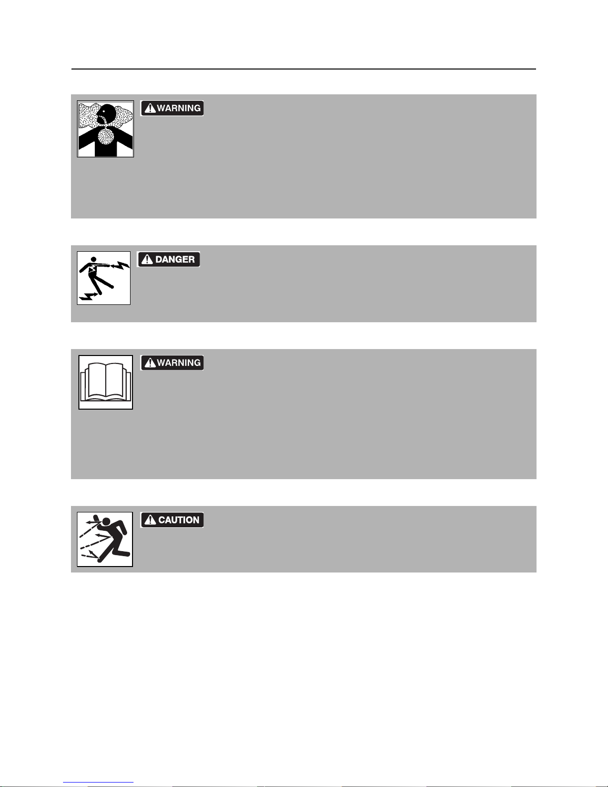
indicates an imminently hazardous situation which, if not avoided, will result in death or
serious injury.
indicates a potentially hazardous situation which, if not avoided, could result in death or
serious injury.
indicates a potentially hazardous situation which, if not avoided, may result in minor or
moderate injury.
Watch for two other words: NOTICE and IMPORTANT.
NOTICE can keep you from doing something that might damage the machine or someone's property. It
can also alert you against unsafe practices.
IMPORTANT can help you do a better job or make your job easier in some way.
CMW

Safety - 12 1330 Operator’s Manual
Safety Alerts
Safety Alerts
Moving digging teeth will kill you or cut off arm or leg. Stay away.
Turning shaft will kill you or crush arm or leg. Stay away.
Electric shock. Contacting electric lines will cause death or serious injury.
Know location of lines and stay away.
Deadly gases. Lack of oxygen or presence of gas will cause sickness or
death. Provide ventilation.
correct equipment and work methods. Use and maintain proper safety
equipment.
proper procedures and equipment or stay away.
Jobsite hazards could cause death or serious injury. Use
Crushing weight could cause death or seriou s injur y. Use
Moving parts could cut off hand or foot. Stay away.
CMW

1330 Operator’s Manual Safety - 13
Safety Alerts
Explosion possible. Serious injury or equipment damage could occur.
Follow directions carefully .
Incorrect procedures could result in death, injury, or property damage.
Learn to use equipment correctly.
Improper control function could cause death or serious injury. If control does
not work as described in instructions, stop machine and have it serviced.
Looking into fiber optic cable could result in permanent vision damage. Do
not look into ends of fiber optic or unidentified cable.
Pressurized fluid or air could pierce skin a nd cause injur y or
death. St ay away.
Fire or explosion possible. Fumes could ignite and cause burns. No
smoking, no flame, no spark.
Moving traffic - hazardous situation. Death or serious injury could result.
Avoid moving vehicles, wear high visibility clothing, post appropriate warning signs.
CMW

Safety - 14 1330 Operator’s Manual
Safety Alerts
Hot pressurized cooling system fluid could cause serious burns. Allow to
cool before servicing.
Flying objects may cause injury. Wear hard hat and safety glasses.
Hot parts may cause burns. Do not touch until cool.
Exposure to high noise levels may cause hearing loss. Wear hearing
protection.
Fall possible. Slips or trips may result in injury. Keep area clean.
Battery acid may cause burns. Avoid contact.
Improper handling or use of chemicals may result in illness, injury, or
equipment damage. Follow instructions on labels and in material safety data sheets
(MSDS).
CMW

1330 Operator’s Manual Safety - 15
Emergency Procedures
Emergency Procedures
Jobsite hazards could cause death or serious injury. Use
correct equipment and work methods. Use and maintain proper safety
equipment.
Before operating any equipment, review emergency proc edures and check that all safety precau tions have
been taken.
EMERGENCY SHUTDOWN - Release operator presence device and turn ignition switch to STOP.
Electric Strike Description
Electric shock. Contacting electric lines will cause death or serious injury.
Know location of lines and stay away.
When working near electric cables, remember the following:
• Electricity follows all paths to ground, not just path of least resistance.
• Pipes, hoses, and cables will conduct electricity back to all equipment.
• Low voltage current can injure or kill. Many work-related electrocutions result from contact with less
than 440 volts.
Most electric strikes are not noticeable, but indications of a strike include:
• power outage
•smoke
•explosion
• popping noises
• arcing electricity
If any of these occur, assume an electric strike has occurred.
CMW

Safety - 16 1330 Operator’s Manual
Emergency Procedures
If an Electric Line is Damaged
If you suspect an electric line has been damaged and you are near pedestrian unit, DO NOT MOVE and
do not touch unit. Take the following actions. The order and degree of action will depend upon the
situation.
• Warn people nearby that an electric strike has occurred. Instruct them to leave the area and contact
utility.
• Do not allow anyone into area until given permission by utility company.
• Do not allow anyone to touch equipment.
If a Gas Line is Damaged
Fire or explosion possible. Fumes could ignite and cause burns. No
smoking, no flame, no spark.
Explosion possible. Serious injury or equipment damage could occur.
Follow directions carefully.
If you suspect a gas line has been damaged, take the following actions. The order and degree of action will
depend on the situation.
• Immediately shut off engine(s), if this can be done safely and quickly.
• Remove any ignition source(s), if this can be done safely and quickly.
• Warn others that a gas line has been cut and that they should leave the area.
• Leave jobsite as quickly as possible.
• Immediately call your local emergency phone number and utility company.
• If jobsite is along street, stop traffic from driving near jobsite.
• Do not return to jobsite until given permission by emergency personnel and utility company.
CMW

1330 Operator’s Manual Safety - 17
Emergency Procedures
If a Fiber Optic Cable is Damaged
Do not look into cut ends of fiber optic or unidentified cable. Vision damage can occur.
If Machine Catches on Fire
Perform emergency shutdown procedure and then take the following actions. The order and degree of
action will depend on the situation.
• Immediately move battery disconnect switch (if equipped) to disconnect position.
• If fire is small and fire extinguisher is available, attempt to extinguish fire.
• If fire cannot be extinguished, leave area as quickly as possible and contact emergency personnel.
CMW

Safety - 18 1330 Operator’s Manual
Emergency Procedures
CMW

1330 Operator’s Manual Controls - 19
Controls
Chapter Contents
Control Console . . . . . . . . . . . . . . . . . . . . . . . . . . . 20
Engine Controls . . . . . . . . . . . . . . . . . . . . . . . . . . . 23
CMW

Controls - 20 1330 Operator’s Manual
Control Console
Control Console
1. Throttle (orange)
2. Boom lift control (green)
3. Speed/direction control (orange)
4. Digging chain control (yellow)
Item Description Notes
1. Throttle (orange) To increase engine speed,
push down.
To decrease engine speed,
pull up.
2. Boom lift control
(green)
To lower boom, push.
To raise boom, pull.
5. Bail (red, operator presence device)
6. Ignition switch
7. Manual start bypass button
8. Axle lock (blue)
Increasing engine speed also
increases digging chain speed.
Bail must be down for this control to
function.
CMW

1330 Operator’s Manual Controls - 21
Control Console
Item Description Notes
3. Speed/direction control
(orange)
To drive, move to DRIVE slot,
then slowly forward or
reverse.
To trench, move to DIG slot,
then slowly pull to desired
speed.
To load onto truck or trailer,
move to LOAD slot, then
slowly push to desired speed.
To go faster in any slot, move
farther from N (neutral).
Bail must be down for this control to
function.
NOTICE: Trenching movement is
always backward (toward you).
4. Digging chain control
(yellow)
5. Bail (red, operator
presence device)
T o st art digging chain, push to
DIG position.
To stop digging chain, move
to N (neutral).
To dislodge a rock or other
obstruction, pull back.
T o enable g round drive and/or
trenching controls, move bail
down into handlebar.
To disable ground drive and/
or trenching controls but keep
engine running, release.
Bail must be down for this control to
function.
NOTICE: Do not attempt to trench
with control pulled toward you.
CMW

Controls - 22 1330 Operator’s Manual
Control Console
Item Description Notes
6. Ignition switch Units with rope start:
To turn power on, turn
clockwise to middle position.
Engine will start when rope is
pulled.
To stop engine, turn
counterclockwise.
Units with electric start:
To start engine, turn all the
way clockwise.
To stop engine, turn
counterclockwise.
7. Manual start bypass
button
8. Axle lock (blue) To unlock axle, push.
To bypass electric start
system and allow manual
rope start with dead battery:
• Turn ignition switch to
ON.
• Push and hold bypass
button while pulling rope
to start engine.
• Release bypass button
when engine starts.
To lock axle, pull.
IMPORTANT: If ignition switch is not
in ON position, engine will start but
will not continue running after bypass
button is released.
Use unlocked axle to maneuver
trencher.
Use locked axle for loading, straight
trenching, and driving over rough
terrain.
CMW

1330 Operator’s Manual Controls - 23
Engine Controls
Engine Controls
1. Fuel shut-off valve
2. Choke
Item Description Notes
1. Fuel shut-off valve When transporting unit to or
from jobsite, or anytime
machine is parked, close
valve.
Before starting engine, open
valve.
2. Choke To help start cold engine,
close valve.
3. Rope start To start engine, pull rope. Engine power switch and ignition
3. Rope start
4. Engine power switch
This valve separates the fuel tank
from the engine.
This valve regulates air/fuel mixture.
switch must be on and fuel shut-off
valve open for this control to function.
If engine does not start after three
pulls, turn power switch off and check
for fuel blockage or electrical system
problems.
4. Engine power switch To turn power on, turn
clockwise.
To turn power off, turn
counterclockwise.
For normal operation, leave this
switch on all the time and use ignition
switch to power unit.
CMW

Controls - 24 1330 Operator’s Manual
CMW

1330 Operator’s Manual Operation Overview - 25
Operation Overview
Chapter Contents
Planning. . . . . . . . . . . . . . . . . . . . . . . . . . . . . . . . . . 26
Trenching. . . . . . . . . . . . . . . . . . . . . . . . . . . . . . . . . 26
Leaving Jobsite. . . . . . . . . . . . . . . . . . . . . . . . . . . . 26
CMW

Operation Overview - 26 1330 Operator’s Manual
Planning
Planning
1. Gather information about jobsite. See page 28.
2. Inspect jobsite. See page 29.
3. Classify jobsite. See page 30.
4. Select best chain type and tooth pattern for your application. See page 51.
5. Consider optional equipment, if necessary. See page 52.
6. Check supplies and prepare equipment. See page 32.
7. Load unit onto truck or trailer. See page 40.
Trenching
1. Unload unit from truck or trailer. See page 42.
2. Start unit. See page 34.
3. Drive to starting point of trench. See page 34.
4. Dig the trench. See page 47.
NOTICE: If trencher becomes disabled and must be moved without engine running, see
page 43 for important instructions.
5. Shut down unit. See page 35.
Leaving Jobsite
1. Restore the jobsite. See page 54.
2. Rinse unit and stow tools. See page 54.
3. Load unit onto trailer. See page 40.
CMW

1330 Operator’s Manual Prepare - 27
Prep are
Chapter Contents
Gather Information . . . . . . . . . . . . . . . . . . . . . . . . . 28
• Review Job Plan . . . . . . . . . . . . . . . . . . . . . . . . . . . . . . . . . . . . . . . . . . .28
• Notify One-Call Services. . . . . . . . . . . . . . . . . . . . . . . . . . . . . . . . . . . . .28
• Arrange for Traffic Control. . . . . . . . . . . . . . . . . . . . . . . . . . . . . . . . . . . .28
• Plan for Emergency Services . . . . . . . . . . . . . . . . . . . . . . . . . . . . . . . . .28
Inspect Site . . . . . . . . . . . . . . . . . . . . . . . . . . . . . . . 29
• Identify Hazards . . . . . . . . . . . . . . . . . . . . . . . . . . . . . . . . . . . . . . . . . . .29
Classify Jobsite. . . . . . . . . . . . . . . . . . . . . . . . . . . . 30
• Inspect Jobsite . . . . . . . . . . . . . . . . . . . . . . . . . . . . . . . . . . . . . . . . . . . .30
• Select a Classification. . . . . . . . . . . . . . . . . . . . . . . . . . . . . . . . . . . . . . .30
• Apply Precautions. . . . . . . . . . . . . . . . . . . . . . . . . . . . . . . . . . . . . . . . . .31
Check Supplies and Prepare Equipment . . . . . . . 32
• Supplies . . . . . . . . . . . . . . . . . . . . . . . . . . . . . . . . . . . . . . . . . . . . . . . . .32
• Fluid Levels. . . . . . . . . . . . . . . . . . . . . . . . . . . . . . . . . . . . . . . . . . . . . . .32
• Condition and Function. . . . . . . . . . . . . . . . . . . . . . . . . . . . . . . . . . . . . .32
• Accessories. . . . . . . . . . . . . . . . . . . . . . . . . . . . . . . . . . . . . . . . . . . . . . .32
CMW

Prepare - 28 1330 Operator’s Manual
Gather Information
Gather Information
A successful job begins before you dig. The first step in planning is revie wing information already available
about the job and jobsite.
Review Job Plan
Review blueprints or other plans. Check for information about exi sting or planned structur es, elevations, or
proposed work that may be taking place at the same time.
Notify One-Call Services
Contact your local One-Call (811 in USA) or the One-Call referral number (888-258-0808 in USA and
Canada) to have underground utilities located before digging. Also contact any utilities that do not
participate in the One-Call service.
Arrange for Traffic Control
If working near a road or other traffic area, contact local authorities about safety procedures and
regulations.
Plan for Emergency Services
Have the telephone numbers for local emergency and medical facilities on hand. Check that you will have
access to a telephone.
CMW

1330 Operator’s Manual Prepare - 29
Inspect Site
Inspect Site
Inspect jobsite before transporting equipment. Check for the following:
• changes in elevation such as hills or other open trenches
• obstacles such as buildings, railroad crossings, or streams
• signs of utilities (See “Inspect Jobsite” on page 30.)
•traffic
•access
• soil type and condition
Identify Hazards
Identify safety hazards and classify jobsite. See “Classify Jobsite” on page 30.
Jobsite hazards could cause death or serious injury. Use
correct equipment and work methods. Use and maintain proper safety
equipment.
NOTICE:
• Wear personal protective equipment including hard hat, safety eye wear, and hearing protection.
• Do not wear jewelry or loose clothing.
• Notify One-Call and companies which do not subscribe to One-Call.
• Comply with all utility notification regulations before digging or drilling.
• Verify location of previously marked underground hazards.
• Mark jobsite clearly and keep spectators away.
Remember, jobsite is classified by hazards in place -- not by line being installed.
CMW

Prepare - 30 1330 Operator’s Manual
Classify Jobsite
Classify Jobsite
Inspect Jobsite
• Follow U.S. Department of Labor regulations on excavating and trenching (Part 1926, Subpar t P) and
other similar regulations.
• Contact your local One-Call (811 in USA) or the One-Call referral number (888-258-0808 in USA and
Canada) to have underground utilities located before digging. Also contact any utilities that do not
participate in the One-Call service.
• Inspect jobsite and perimeter for evidence of underground hazards, such as:
– “buried utility” notices
– utility facilities without overhead lines
– gas or water meters
– junction boxes
– drop boxes
– light poles
– manhole covers
– sunken ground
• Have an experienced locating equipment operator sweep area within 20 feet (6 m) to each side of
trench path. Verify previously marked line and cable locations.
• Mark location of all buried utilities and obstructions.
• Classify jobsite.
Select a Classification
Jobsites are classified according to underground hazards present.
If working . . . then classify jobsite as . . .
within 10 ft (3 m) of a buried electric line electric
within 10 ft (3 m) of a natural gas line natural gas
in sand or granite which is capable of producing crystalline silica
(quartz) dust
within 10 ft (3 m) of any other hazard other
NOTICE: If you have any doubt about jobsite classification, or if jobsite might contain unmarked
hazards, take steps outlined previously to identify hazards and classify jobs ite be fo re wor kin g.
crystalline silica (quartz) dust
CMW

1330 Operator’s Manual Prepare - 31
Classify Jobsite
Apply Precautions
Once classified, precautions appropriate for jobsite must be taken.
Electric Jobsite Precautions
Use one or both of these methods.
• Expose line by careful hand digging or soft excavation.
• Have service shut down while work is in progress. Have electric company test lines before returning
them to service.
Natural Gas Jobsite Precautions
In addition to positioning equipment upwind from gas lines, use one or both of these methods.
• Expose lines by careful hand digging or soft excavation.
• Have gas shut off while work is in progress. Have gas company test lines before returning them to
service.
Crystalline Silica (Quartz) Dust Precautions
NOTICE: Cutting, drilling, or working materials such as concrete, sand, or rock containing quartz may
result in exposure to silica dust. Use water spray or other means to control dust. If workers are exposed to
dust they must wear appropriate breathing protection. Silica dust may cause lung disease and is known to
the State of California to cause cancer.
Other Jobsite Precautions
You may need to use different methods to safely avoid other underground hazards. Talk with those
knowledgeable about hazards present at each site to determine which precautions should be taken or if
job should be attempted.
CMW

Prepare - 32 1330 Operator’s Manual
Check Supplies and Prepare Equipment
Check Supplies and Prepare Equipment
Supplies
•fuel
•keys
• personal protective equipment, such as hard hat and safety glasses
Fluid Levels
•fuel
• hydraulic fluid
• battery charge
• engine oil
Condition and Function
• digging chain and teeth
• filters (air, oil, hydraulic)
• tires and tracks
• pumps and motors
• hoses and valves
• signs, guards, and shields
Accessories
Fire Extinguisher
If required, mount a fire extinguisher near the power unit but away from possible points of ignition. The fire
extinguisher should always be classified for both oil and electric fires. It should meet legal and regulatory
requirements.
CMW

1330 Operator’s Manual Drive - 33
Drive
Chapter Contents
Start Unit . . . . . . . . . . . . . . . . . . . . . . . . . . . . . . . . . 34
Drive. . . . . . . . . . . . . . . . . . . . . . . . . . . . . . . . . . . . . 34
Steer. . . . . . . . . . . . . . . . . . . . . . . . . . . . . . . . . . . . . 35
Shut Down. . . . . . . . . . . . . . . . . . . . . . . . . . . . . . . . 35
CMW

Drive - 34 1330 Operator’s Manual
Start Unit
Start Unit
1. Check that bail is up, fuel shut-off valve is open, and engine power switch is on.
2. If necessary, choke cold engine.
3. Move throttle to 1/4 open.
4. Turn ignition switch on.
5. Pull rope start, if equipped.
IMPORTANT:
• If engine does not start after three pulls, turn ignition switch off and check for fuel blockage
or electrical system problems.
• To rope start electric start unit with dead battery, see “Manual start bypass button” on
page 22.
6. Run engine at half throttle or less for five minutes before operating trencher. During warmup, check
that all controls work properly.
EMERGENCY SHUTDOWN: Release operator presence device and turn ignition switch off.
Drive
NOTICE: Keep digging boom low when operating on a slope. Drive slowly and cautiously at all times.
1. Move bail down into handlebar.
Improper control function could cause death or serious injury. If
control does not work as described in instructions, stop machine and have it
serviced.
NOTICE:
• If interlock system does not work, contact your Ditch Witch dealer. Improper repair might
allow machine to start or operate with controls in gear.
• Do not wire or tape bail to handlebar or defeat interlock system in any manner. Machine
will not start.
2. Pull boom control to raise digging boom.
3. In rough terrain or to drive straight, push axle lock to lock wheels together.
4. Move throttle to 3/4 open.
5. Move speed/direction control to DRIVE slot, then slowly forward or reverse.
CMW

1330 Operator’s Manual Drive - 35
Steer
Steer
1. Push axle lock to unlock wheels.
2. Push down on handlebar.
3. Turn machine.
Shut Down
1. Move speed/direction control to N (neutral).
2. Push boom control to lower digging boom, if space allows.
3. Release bail.
4. Run engine at low idle for three minutes to cool.
5. Turn ignition switch off.
6. Close fuel shut-off valve
7. Remove key.
NOTICE: Machine should not be parked on a slope unless chocked or blocked.
CMW

Drive - 36 1330 Operator’s Manual
Shut Down
CMW

1330 Operator’s Manual Transport - 37
Transport
Chapter Contents
Lift . . . . . . . . . . . . . . . . . . . . . . . . . . . . . . . . . . . . . . 38
• Points . . . . . . . . . . . . . . . . . . . . . . . . . . . . . . . . . . . . . . . . . . . . . . . . . . .38
• Procedure . . . . . . . . . . . . . . . . . . . . . . . . . . . . . . . . . . . . . . . . . . . . . . . .38
Haul . . . . . . . . . . . . . . . . . . . . . . . . . . . . . . . . . . . . . 39
• Inspect Trailer . . . . . . . . . . . . . . . . . . . . . . . . . . . . . . . . . . . . . . . . . . . .39
• Hitch Trailer . . . . . . . . . . . . . . . . . . . . . . . . . . . . . . . . . . . . . . . . . . . . . .39
• Load . . . . . . . . . . . . . . . . . . . . . . . . . . . . . . . . . . . . . . . . . . . . . . . . . . . .40
• Tie Down . . . . . . . . . . . . . . . . . . . . . . . . . . . . . . . . . . . . . . . . . . . . . . . .41
• Unload . . . . . . . . . . . . . . . . . . . . . . . . . . . . . . . . . . . . . . . . . . . . . . . . . .42
• Unhitch Trailer . . . . . . . . . . . . . . . . . . . . . . . . . . . . . . . . . . . . . . . . . . . .42
Freewheel . . . . . . . . . . . . . . . . . . . . . . . . . . . . . . . . 43
Tow . . . . . . . . . . . . . . . . . . . . . . . . . . . . . . . . . . . . . 43

Transport - 38 1330 Operator’s Manual
Lift
Lift
Crushing weight. If load falls or moves it could kill or crush you. Use
proper procedures and equipment or st ay away.
Points
Lifting points are identified by lifting decals. Lifting at other points is unsafe
and can damage machinery.
Procedure
Use a hoist capable of supporting the equipment's size and weight. See “Specifications” on page 75 or
measure and weigh equipment before lifting.
Run a sling through the front guide, under handlebar, and around back of console tower.

1330 Operator’s Manual Transport - 39
Haul
Haul
IMPORTANT: The 1330 can be hauled in the bed of a light truck or by trailer. If using a trailer, follow
these general procedures. For complete information, see the trailer manufacturer’s manual.
Inspect Trailer
• Check hitch for wear and cracks. Lubricate if needed.
• Check battery for 12 volt charge, if installed.
• Inspect lights for cleanliness and correct operation. Inspect reflectors and replace if needed.
• Check tire pressure. Check lug nut torque with a torque wrench. Adjust if needed.
• If equipped, ensure trailer brakes are adjusted to come on in synchronization with tow vehicle brakes.
• Check ramps and trailer bed for cracks.
Hitch Trailer
1. Back tow vehicle to trailer.
2. Put manual transmission into first or reverse gear or automatic transmission into park. Turn off ignition.
Set parking brake.
3. Connect trailer drawbar, lunette or coupler to tow vehicle hitch and lock in place with lock pin. If
needed, adjust drawbar, lunette or coupler height to level load.
4. Connect safety chains to tow vehicle chain keepers (cross-shaped slots on bumper of tow vehicle).
Attach left chain to right side of tow vehicle and vice versa to cradle hitch.
IMPORTANT: Do not connect safety chains to pintle hook or hitch ball.
5. If equipped, connect breakaway switch cable to tow vehicle.
IMPORTANT: Do not connect breakaway switch cable to pintle hook or hitch ball.
6. If equipped, plug trailer electrical connector into tow vehicle connector.
7. If equipped, use jack crank to raise jack base and stow.
8. Remove wheel blocks.

Transport - 40 1330 Operator’s Manual
Haul
Load
Crushing weight. If load falls or moves it could kill or crush you. Use
proper procedures and equipment or st ay away.
NOTICE:
• Load and unload trailer on level ground.
• Incorrect loading can cause trailer swaying.
• Attach trailer to vehicle before loading or unloading.
• Ten to fifteen percent of total vehicle weight (equipment plus trailer) must be on tongue to help
prevent trailer sway.
1. Start engine.
2. Pull boom control to raise digging boom, but keep it low.
3. Move trencher to rear of trailer or truck and align with ramps or center of trailer bed.
IMPORTANT: Boom should be facing ramps or trailer.
4. Pull axle lock to lock wheels together.
5. Slow engine to low throttle.
6. Move speed/direction control to LOAD slot, then slowly push to desired speed.
7. Drive unit onto trailer or truck, digging boom first, until tiedown position is reached.
NOTICE: If loading onto tilt-bed trailer, be prepared for trailer to tilt.
8. Push boom control to lower digging boom, if space allows.
9. Turn ignition switch off.
10. Clo se fuel sh ut -o ff valve.

1330 Operator’s Manual Transport - 41
Haul
Tie Down
Points
Tiedown points are identified by tiedown decals. Securing to truck or trailer
at other points is unsafe and can damage machinery.
Procedure
Loop tiedowns around unit at tiedown points. Make sure tiedowns are tight before transporting.

Transport - 42 1330 Operator’s Manual
Haul
Unload
Crushing weight. If load falls or moves it could kill or crush you. Use
proper procedures and equipment or st ay away.
NOTICE:
• Load and unload trailer on level ground.
• Attach trailer to vehicle before loading or unloading.
1. Lower trailer or ramps.
2. Remove tiedowns.
3. Open fuel shut-off valve.
4. Start engine.
5. Pull boom control to raise digging boom, but keep it low.
6. Slow engine to low throttle and slowly back unit down trailer or ramps.
NOTICE: If unloading from tilt-bed trailer, be prepared for trailer to tilt.
Unhitch Trailer
1. Stop tow vehicle and trailer on level ground.
2. Put manual transmission into first or reverse gear or automatic transmission into park. Turn off ignition.
Set parking brake.
3. Block trailer wheels.
4. Reverse “Hitch Trailer“ steps to unhitch trailer from tow vehicle.

1330 Operator’s Manual Transport - 43
Freewheel
Freewheel
If trencher must be moved without engine running, this feature allows it to be wheeled manually.
Crushing weight could cause death or serious injury. Use proper
procedures and equipment or stay awa y.
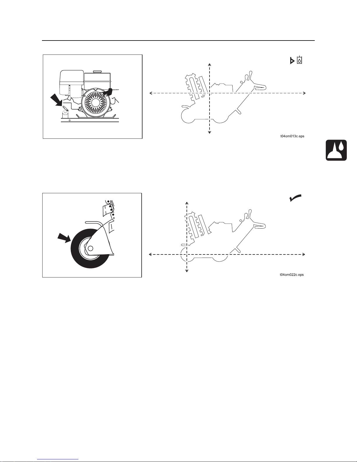
1. Elevate left side of trencher with jackstand or
safety blocks.
2. Remove nut from left wheel hub.
3. Horizontally align two of the three threaded holes
(A) in wheel hub with machine frame, as shown.
4. Insert bolts (supplied in operator’s manual
compartment) into threaded holes and tighten until
wheel is released from axle.
5. Remove key (B) from axle.
6. Replace wheel and hub, and tighten only enou g h
to keep hub on axle. Overtightening can lock hub
to axle.
7. Wheel trencher to a clear area of the jobsite.
NOTICE: Do not freewheel the trencher
more than 100 ft (30 m). Damage to wheel
hub or axle will occur.
Tow
Under normal conditions, unit should not be towed. If unit breaks down and towing is necessary:
• follow “Freewheel” instructions
• tow for short distances at less than 1 mph (1.6 kph)
• do not tow for more than 100 ft (30 m)
• attach chains to indicated tow points facin g towing vehicle
• use no more than 1,300 lb (5800 N) of towing force

Transport - 44 1330 Operator’s Manual
Tow

1330 Operator’s Manual Trench - 45
Trench
Chapter Contents
Trench . . . . . . . . . . . . . . . . . . . . . . . . . . . . . . . . . . . 47
Trench - 46 1330 Operator’s Manual
Jobsite hazards could cause death or seriou s injury. Use correct
equipment and work methods. Use and maintain proper safety equipment.
NOTICE: Cutting, drilling or working materials such as concrete, sand, or rock containing quartz may
result in exposure to silica dust. Use water spray or other means to control dust. If workers are exposed
to dust, they must wear appropriate breathing protection. Silica dust may cause lung disease and is
known to the State of California to cause cancer.
Electrical shock. Contacting electrical lines will cause death or serious
injury. Know location of lines and stay away.
NOTICE: Cutting high voltage cable can cause electrocuti on. Expose lines by hand befo re
digging.
Incorrect procedures could result in death, injury, or property damage.
Learn to use equipment correctly.
NOTICE:
• Comply with all utility notification regulations before digging or drilling.
• Notify companies that do not subscribe to One-Call.
Flying objects thrown by machine may strike people. Wear hard hat and
safety glasses.

1330 Operator’s Manual Trench - 47
Trench
Trench
1. Drive trencher to starting point. Move in line with planned trench.
2. Pull axle lock to lock wheels together.
3. Move throttle to half open.
4. Push boom control to lower digging boom to just above ground.
Moving digging teeth will cause death or serious injury. Stay away.
NOTICE:
• Keep everyone at lease 6 ft (2 m) from machine, digging boom, and its range of movement.
• Machine may move when chain starts to dig. Allow 3 ft (1 m) between end of chain and obstacle.
• Digging chain on top side of boom can catch on root or rock, forcing handlebar down suddenly.
Stand back from console and hold handlebar loosely.
5. Push digging chain control to DIG. DIGGING
CHAIN WILL MOVE.
EMERGENCY STOP: Release operator
presence device and turn ignition switch off.
IMPORTANT: Trenching movement is
toward you.
6. Increase engine speed to full throttle.

Trench - 48 1330 Operator’s Manual
Trench
7. Push boom control to slowly lower digging boom to desired trench depth.
8. Move speed/direction control to DIG, then slowly pull to desired speed.
IMPORTANT:
• Do not make sharp turns. Lower boom to full depth when turning.
• If an object becomes lodged in chain, move attachment speed/direction control to neutral and raise
boom slightly. Reverse chain direction. If object must be removed manually, turn engine off and
engage parking brake.
9. When trench is complete, push speed/direction control to N (neutral).
10. Move throttle to half open.
11. Pull boom control to raise digging boom to top of trench.
12. Pull digging chain control to N (neutral).
13. Drive away from trench.
14. See page 35 for shutdown procedure.

1330 Operator’s Manual Systems and Equipment - 49
Systems and Equipment
Chapter Contents
Chain, Teeth, and Sprockets . . . . . . . . . . . . . . . . . 50
• Chain and Tooth Maintenance . . . . . . . . . . . . . . . . . . . . . . . . . . . . . . . .50
• Chain Types . . . . . . . . . . . . . . . . . . . . . . . . . . . . . . . . . . . . . . . . . . . . . .50
• Chain Selection. . . . . . . . . . . . . . . . . . . . . . . . . . . . . . . . . . . . . . . . . . . .51
Optional Equipment . . . . . . . . . . . . . . . . . . . . . . . . 52

Systems and Equipment - 50 1330 Operator’s Manual
Chain, Teeth, and Sprockets
Chain, Teeth, and Sprockets
Chain and Tooth Maintenance
• Always replace sprockets at the same time you replace the digging chain. Sprockets and chain are
designed to work together. Replacing one without the other will cause premature wear of the new part.
• Keep digging teeth sharp. Using dull, worn teeth will decrease production and increase shock load to
other trencher components. It can also cause chain stretch, which leads to premature chain wear and
failure.
• Maintain the proper amount of tension on the digging chain. Overtightening will cause chain stretch
and loss of machine performance. For correct tightening procedure, see pag e 65.
• Use the tooth pattern most appropriate for your digging conditions. If you move to a different soil type,
contact your Ditch Witch dealer for information about the most effective chain type and tooth pattern.
Chain Types
Chain type Features
4-pitch standard chain
2-pitch more teeth for smoother cuttin g
alternating side bar prevents spoil compaction on chain
bolt-on adapters allow easy configuration changes
Shark Chain II versatile, virtually maintenance- fr ee
combination provides pick and shovel effect

1330 Operator’s Manual Systems and Equipment - 51
Chain, Teeth, and Sprockets
Chain Selection
These charts are meant as a guideline only. No one chain type works well in all conditions. See your Ditch
Witch dealer for soil conditions and chain recommendations for your area. Ask for the latest Chain, Teeth,
and Sprockets Parts Catalog.
• 1 = best
• 2 = better
• 3 = good
• 4 = not recommended
Chain Sandy
Soil
4-pitch cup tooth 3 1 2 3 4 1
2-pitch cup tooth 2 3 1 1 3 4
bolt-on adaptor, 2-pitch 4 4 3 2 1 4
bolt-on adaptor/cup tooth
combo
Shark Chain II 432114
alternating side bar 4 4 4 4 4 1
Soil Description
sandy soil sugar sand, blow sand, or other soils where sand is the predominant component
soft soil sandy loam
medium soil loams, loamy clays
hard soil packed clays, gumbo, all compacted soils
432124
Soft Soil Medium
Soil
Hard Soil Rocky
Soil
Sticky
Soil
rocky soil chunk rock, glacial till, cobble, rip rap, gravel
sticky soil gumbo, sticky clays

Systems and Equipment - 52 1330 Operator’s Manual
Optional Equipment
Optional Equipment
See your Ditch Witch dealer for more information about the following optional equipment.
Equipment Description
booms provide depth options of 24-in (610- mm), 30-in (760-mm), or 36-in (915 mm);
each length is available with either an adjustment screw or grease cylinder
for tensioning the digging chain
mechanical trench cleaner removes spoils from the trench floor
remote air filter provides extra filtering capacity for dusty conditions
turf tires minimize turf disturbance
tachometer displays engine speed

1330 Operator’s Manual Complete the Job - 53
Complete the Job
Chapter Contents
Restore Jobsite. . . . . . . . . . . . . . . . . . . . . . . . . . . . 54
Rinse Equipment . . . . . . . . . . . . . . . . . . . . . . . . . . 54
Stow Tools . . . . . . . . . . . . . . . . . . . . . . . . . . . . . . . 54
CMW

Complete the Job - 54 1330 Operator’s Manual
Restore Jobsite
Restore Jobsite
After product is installed, return spoils to the trench with shovels or small earth-moving equipment.
Rinse Equipment
Spray water onto equipment to remove dirt and mud.
NOTICE: Do not spray water onto operator’s console. Electrical components could be damaged. Wipe
down instead.
Stow Tools
Make sure all tools and accessories are loaded and properly secured on trailer.
CMW

1330 Operator’s Manual Service - 55
Service
Chapter Contents
Service Precautions . . . . . . . . . . . . . . . . . . . . . . . . 56
Overview . . . . . . . . . . . . . . . . . . . . . . . . . . . . . . . . . 57
Recommended Lubricants/Service Key . . . . . . . . 58
Oil Temperature Chart . . . . . . . . . . . . . . . . . . . . . . 59
Each Use Service . . . . . . . . . . . . . . . . . . . . . . . . . . 60
10 Hour Service. . . . . . . . . . . . . . . . . . . . . . . . . . . . 64
20 Hour Service. . . . . . . . . . . . . . . . . . . . . . . . . . . . 67
50 Hour Service. . . . . . . . . . . . . . . . . . . . . . . . . . . . 69
100 Hour Service. . . . . . . . . . . . . . . . . . . . . . . . . . . 71
250 Hour Service. . . . . . . . . . . . . . . . . . . . . . . . . . . 73
500 Hour Service. . . . . . . . . . . . . . . . . . . . . . . . . . . 74
CMW

Service - 56 1330 Operator’s Manual
Service Precautions
Service Precautions
Incorrect procedures could result in death, injury, or property damage.
Learn to use equipment correctly.
NOTICES:
• Unless otherwise instructed, all service should be performed with engine off.
• Refer to engine manufacturer’s manual for engine maintenance instructions.
• Before servicing equipment, lower unstowed attachments to ground.
Jump Starting Precaution
NOTICE: Improper jump starting could cause damage engine. To jump start, stop the engine of the
service vehicle before connecting jumper cables.
Welding Precaution
NOTICE: Welding can damage electronics.
• Disconnect battery at battery disconnect switch before welding to prevent damage to battery.
Do not turn off battery disconnect switch with engine running or alternator and other electronic
devices may be damaged.
• Connect welder ground clamp close to welding point and make sure no electronic components
are in the ground path.
• Always disconnect the ECU ground connection from the fra me, harness connections to the ECU,
and other electronic components prior to welding on machine or attachments.
Cleaning Precaution
NOTICE: When cleaning equipment, do not spray electrical components with water.
CMW

1330 Operator’s Manual Service - 57
Overview
Overview
CMW

Service - 58 1330 Operator’s Manual
Recommended Lubricants/Service Key
Recommended Lubricants/Service Key
Item Description
GEO Gasoline engine oil meeting current API service classifications and SAE viscosity
recommended by engine manufacturer (SAE 10W40)
MPG Multipurpose grease meeting ASTM D217 and NLGI 5
AGMA-7 Worm gear lubricant matching American Gear Manufacturer’s Association Compound
#7
THF Tractor hydraulic fluid, similar to Phillips 66 HG, Mobilfluid 423, Chevron Tractor
Hydraulic Fluid, Texaco TDH Oil, or equivalent
Check level of fluid or lubricant
Check condition
Filter
Change, replace, adjust, service or test
Proper lubrication and maintenance protects Ditch Witch equipment from damage and failure. Service
intervals listed are for minimum requirements. In ex treme conditions, service machine more frequently.
Use only recommended lubricants. Fill to capacities listed in “Specifications” on page 75.
NOTICE:
• Use only genuine Ditch Witch parts, filters, and approved lubricants to maintain warranty.
• Use the “Service Record” on page 83 to record all required service to your machine.
CMW

1330 Operator’s Manual Service - 59
Engine Oil Temperature Chart
Engine Oil Temperature Chart
30 10W- 30 10W- 40
10W- 30 10W- 40
5W- 20 5W- 30
-20
F
-30 -20
C
j07om070h.eps
For more information on engine lubrication and maintenance, see your engine manual.
0
Temperature range anticipated before next oil change
20
10 0 10 20 30 40
40
60
80 100
CMW

Service - 60 1330 Operator’s Manual
Each Use Service
Each Use Service
Location Task Notes
Trencher Check engine oil level GEO
Check hydraulic fluid level THF
Check tire pressure 15 psi (1 bar) standard tires
22 psi (1.5 bar) turf tires
Check lug nut torque 85 ft•lb (115 N•m)
Check air filter paper elements
Trencher
Check Engine Oil Level
Check engine oil at either dipstick before each use. If low, fill with GEO until oil level is at highest line on
dipstick.
IMPORTANT: For more information on engine oil, see “Recommended Lubricants/Service Key” on
page 58 or see engine manual.
CMW
1330 Operator’s Manual Service - 61
Each Use Service
Check Hydraulic Fluid Level
With digging boom fully raised, check hydraulic fluid at dipstick before each use. If low, fill with THF until oil
level is at highest line on dipstick. Clean dust from cap by blowing with low pressure air.
Check Tire Pressure
Check trail wheel tire pressure before each use. Maintain pressure at 20 psi (1.4 bar) for standard tires or
22 psi (1.5 bar) for optional turf tires.
CMW

Service - 62 1330 Operator’s Manual
Each Use Service
Check Lug Nut Torque
Check wheel lug nut torque before each use. Tighten to 85 ft•lb (115 N•m).
Check Air Filter Element
Check air filter paper element before each use. Replace element if it is excessively dirty or damaged.
To check:
1. Remove wing nut and air cleaner cover.
2. Remove elements (1, 2) and sep arate them.
3. Replace elements if excessively dirty or damaged.
CMW

1330 Operator’s Manual Service - 63
Each Use Service
Check Optional Air Filter Element
Change optional air cleaner element as needed.
1. Remove remote air cleaner cover.
2. Replace element if it is excessively dirty or damaged.
NOTICE: Replace dirty filters. Attempting to clean them may damage the element.
• Brushing will force dirt into the fibers.
• Using compressed air to blow dirt off filters can puncture the filter.
• Tapping the filter can damage the filter seal.
CMW

Service - 64 1330 Operator’s Manual
10 Hour Service
10 Hour Service
Location Task Notes
Trencher Check hydraulic hoses
Lube pivot MPG
Check digging chain tension MPG
Trencher
Check Hydraulic Hoses
Check hydraulic hoses for leaks every 10 hours.
Fluid or air pressure could pierce skin and cause injury or
death. Stay away.
NOTICE:
• Escaping pressurized fluid can cause injury or pierce skin and poison.
• Before disconnecting a hydraulic line, turn engine off and ope rate all controls to relieve pressure.
Lower, blo ck, or support any raised component with a hoist. Cover connectio n with heavy cloth and
loosen connector nut slightly to relieve residual pressure. Catch all fluid in a container.
• Before using system, check that all connections are tight and all lines are undamaged.
• Fluid leaks can be hard to detect. Use a piece of cardboard or wood, rather than hands, to search
for leaks.
• Wear protective clothing, including gloves and eye protection.
• If you are injured, seek immediate medical attention from a doctor familiar with this type of injury.
CMW

1330 Operator’s Manual Service - 65
10 Hour Service
Lube Pivot
Lube two pivot zerks with MPG every 10 hours.
Check Digging Chain Tension
Check digging chain tension every 10 hours and adjust as needed. With boom horizontal, measure
distance from bottom of boom to chain. When properly tensioned, distance should be .5 in (13 mm).
Adjustment Screw:
1. Loosen four clamp bolts (2) so that boom slides freely.
2. Loosen jam nut on adjustment screw (1).
3. To tighten digging chain, turn adjustment screw clockwise. To loosen digging chain, turn
counterclockwise.
4. When proper tension is reached, tighten jam nut.
5. Torque clamp bolts to 75 ft•lb (102 N•m).
CMW

Service - 66 1330 Operator’s Manual
10 Hour Service
Grease Cylinder:
To tighten digging chain, pump MPG into cylinder at check valve zerk.
NOTICE: Do not overtighten chain. Overtightening will cause chain stretch, loss of machine
performance, and possible premature chain failure.
To loosen digging chain, stand on opposite side of boom and unscrew check valve zerk to release grease.
Fluid pressure could pierce skin and cause injury or death. Stay away.
NOTICE: Service digging boom grease cylinder only while standing on opposite side of
boom. Wear gloves and safety glasses and cover fitting with cloth when relieving pressure
in cylinder.
CMW

1330 Operator’s Manual Service - 67
20 Hour Service
20 Hour Service
Location Task Notes
Trencher Lube trail wheel MPG
Lube axle lock MPG
Lube headshaft bearing MPG
Change engine oil (initial) GEO
Trencher
Lube Trail Wheel
Lube trail wheel with MPG every 20 hours.
Lube Axle Lock
Lube axle lock with MPG every 20 hours.
CMW

Service - 68 1330 Operator’s Manual
20 Hour Service
Lube Headshaft Bearing
Lube headshaft bearing with MPG every 20 hours.
Change Engine Oil
Change engine oil after the first 20 hours of operation and every 100 hours thereafter.
1. Drain (2) while oil is still warm.
2. Replace plug.
3. Refill at fill neck (1) with 2.3 pt (1.1 L) of GEO.
IMPORTANT: If operating in extremely dusty conditions, change oil more frequently. Use oil specified in
temperature chart found in “Recommended Lubricants/Service Key” on page 58.
CMW

1330 Operator’s Manual Service - 69
50 Hour Service
50 Hour Service
Location Task Notes
Trencher Check worm drive oil AGMA-7
Lube digging boom adjustment screw and stub, if
equipped
Lube digging boom stub, if equipped MPG
Trencher
Check Worm Drive Oil
Check worm drive oil at fill plug every 50 hours.
MPG
1. Elevate left side of trencher with a jack capable of supporting its weight.
2. Fill to level of fill plug with AGMA-7 as needed.
3. Replace wheel.
CMW

Service - 70 1330 Operator’s Manual
50 Hour Service
Lube Digging Boom Adjustment Screw and Stub
Lube adjustment screw and stub with MPG every 50 hours.
Lube Digging Boom Stub (Greaseable Boom)
Lube boom stub every 50 hours with MPG.
t04om004h.eps
CMW

1330 Operator’s Manual Service - 71
100 Hour Service
100 Hour Service
Location Task Notes
Trencher Change engine oil GEO
Change air filter element
Trencher
Change Engine Oil
Change engine oil every 100 hours.
1. Drain (2) while oil is still warm.
2. Replace plug.
3. Refill at fill neck (1) with 2.3 pt (1.1 L) of GEO.
IMPORTANT: If operating in extremely dusty conditions, change oil more frequently. Use oil
specified in temperature chart found in “Recommended Lubricants/Service Key” on page 58.
CMW

Service - 72 1330 Operator’s Manual
100 Hour Service
Change Air Filter Element
Change air filter paper element every 100 hours.
To change:
1. Remove wing nut and air cleaner cover.
2. Remove elements and replace.
3. Reverse procedure to install.
CMW

1330 Operator’s Manual Service - 73
250 Hour Service
250 Hour Service
Location Task Notes
Trencher Change hydraulic oil and filter THF
Trencher
Change Hydraulic Oil and Filter
Change hydraulic oil and filter every 250 hours.
1. Drain hydraulic fluid at drain (3).
2. Replace plug.
3. Change filter (2).
4. Refill with THF at fill neck (1).
CMW

Service - 74 1330 Operator’s Manual
500 Hour Service
500 Hour Service
Location Task Notes
Trencher Change worm drive oil AGMA-7
Trencher
Change Worm Drive Oil
Change worm drive oil every 500 hours.
1. Drain oil at drain (1).
2. Replace plug.
3. Refill at fill plug (2) with approximatley 3.25 pt (1.5 L) of AGMA-7.
NOTICE: Do not use a substitute lubricant. Worm drive failure could occur.
CMW

1330 Operator’s Manual Specifications - 75
Specifications
Dimensions U.S. Metric
A Trench depth, maximum 36 in 915 mm
B Trench width 4.3 - 6 in 110-150 mm
C Boom travel down 60° 60°
C1 Boom travel up 60° 60°
F Headshaft height, digging chain 8.6 in 220 mm
L3 Length 84 in 2.1 m
W2 Width 33 in 840 mm
H2 Height 47 in 1.2 m
W4 Tread 26 in 660 mm
A2 Angle of departure 35° 35°
L4 Wheelbase 32 in 810 mm
E1 Centerline trench to outside edge of machine, left 15 in 381 mm
E2 Centerline trench to outside edge of machine , right 18 in 457 mm
N Spoil discharge reach 10.6 in 270 mm
A3 Angle of approach 85° 85°
Unless otherwise noted, dimensions are based on 16x6.50x8 tires, 6-in (150-mm) pivot, and 24-in (610-mm) boom in transport
position.
CMW

Specifications - 76 1330 Operator’s Manual
General
Ditch Witch model 1330, self-propelled, hydrostatic, pedestrian, manually steered, two wheel drive rigid
frame, chain type trencher.
Operational U.S. Metric
Vehicle speeds
Maximum transit forward 120 fpm 37 m/min
Maximum transit reverse 196 fpm 60 m/min
Digging chain speed 275 fpm 84 m/min
Spoils handling (single, ope n-end auger)
Outer diameter 12 in 305 mm
Inner diameter 4 in 102mm
Length 9 in 229 mm
Operating weight (with 33,000-lb [14 969-kg] test, two- pitch digging chain
920 lb 417 kg
and 24-in [610-mm] roller boom)
Power U.S. Metric
Engine: Honda GX390
Fuel: gasoline
Cooling medium: air
Number of cylinders: one
Displacement
23.7 in
3
389 cm
3
Bore 3.53 in 90 mm
Stroke 2.52 in 64 mm
Gross power @ 3600 rpm 13 hp 9.7 kW
Maximum governed speed installed (no load) 3600 rpm 3600 rpm
Flywheel power @ 3200 rpm (full load) 12 hp 8.9 kW
Fuel consumption @ 3600 rpm .89 gph 3.4 L/hr
Maximum tilt angle 20° 20°
Battery
210, 12V
CMW

1330 Operator’s Manual Specifications - 77
Power Train U.S. Metric
Ground drive transmission: hydrostatic, two speeds infinitely variable from zero to maximum, gearbox to
axle, speed and direction controlled with single lever
Digging chain drive: hydraulic direct drive, lever-operated, one speed forward and reverse
Trencher drive: hydraulic direct drive
Pump drive: direct drive from engine
Spoils handling drive: mechanical, attached to and rotates with headshaft
Tires
Drive, standard: 16x6.50x8 15 psi 103 kPa
Drive, optional: 18x8.50x8 22 psi 152 kPa
Trail: 13x5.00x6
Hydraulic System U.S. Metric
Tandem pump capacity @ 3600 rpm
To digging drive 5.7 gpm 21.5 L/min
To ground drive 1.4 gpm 5.3 L/min
Total 7.1 gpm 26.8 L/min
Fluid Capacities U.S. Metric
Hydraulic reservoir 4.5 gal 17 L
Hydraulic system 5 gal 19 L
Worm drive oil 3.25 pt 1.5 L
Fuel tank 1.7 gal 6.5 L
Engine oil 2.3 pt 1.1 L
Noise Levels
Operator 86 dBA sound pressure per ISO 6394
Exterior 100 dBA sound power per ISO 6393
Vibration Levels
Vibration at the operator’s hand during normal operation is 8.4 m/s
2
CMW

Specifications - 78 1330 Operator’s Manual
CMW

1330 Operator’s Manual Support - 79
Procedure
Support
Procedure
Notify your dealer immediately of any malfunction or failure of Ditch Witch equipment.
Always give model, serial number, and approximate date of your equipment purchase. This information
should be recorded and placed on file by the owner at the time of purchase.
Return damaged parts to dealer for inspection and warranty consideration if in warranty time frame.
Order genuine Ditch Witch replacement or repair parts from your authorized Ditch Witch dealer. Use of
another manufacturer's parts may void warranty consideration.
Resources
Publications
Contact your Ditch Witch dealer for publications and videos covering safety, operation, service, and repair
of your equipment.
Ditch Witch Training
For information about on-site, individualized training, contact your Ditch Witch dealer.
CMW

Warranty - 80 1330 Operator’s Manual
Warranty
Ditch Witch Equipment and Parts
Limited Warranty Policy
Subject to the limitations and exclusions herein, free replacement parts will be provided at any authorized Ditch Witch dealership for
any Ditch Witch equipment or parts manufactured by The Charles Machine Works, Inc. (CMW) that fail due to a defect in material or
workmanship within one (1) year of first commercial use (Exception: 2 years for all SK5 attachments). Free labor will be provided at
any authorized Ditch Witch dealership for installation of parts under this warranty during the first year following initial commercial use
of the serial-numbered Ditch Witch equipment on which it is installed.
Exclusions from Product Warranty
• Wear-related failure of parts subject to ground contact including, but not limited to, digging teeth, digging chains, sprockets,
backhoe buckets, plow blades, drill pipe, drill bits, backreamers, and swivels.
• All incidental or consequential damages.
• All defects, damages, or injuries caused by misuse, abuse, improper installation, alteration, neglect, or uses other than those for
which products were intended.
• All defects, damages, or injuries caused by improper training, operation, or servicing of products in a manner inconsistent with
manufacturer’s recommendations.
• All engines and engine accessories (these are covered by original manufacturer’s warranty).
• Tires, belts, and other parts which may be subject to another manufacturer’s warranty (such warranty will be available to
purchaser).
• All implied warranties not expressly stated herein, including any warranty of fitness for a particular purpose and merchantability.
IF THE PRODUCTS ARE PURCHASED FOR COMMERCIAL PURPOSES AS DEFINED BY THE UNIFORM COMMERCIAL CODE,
THEN THERE ARE NO WARRANTIES WHICH EXTEND BEYOND THE FACE HEREOF AND THERE ARE NO IMPLIED
WARRANTIES OF ANY KIND WHICH EXTEND TO A COMMERCIAL BUYER. ALL OTHER PROVISIONS OF THIS LIMITED
WARRANTY APPLY INCLUDING THE DUTIES IMPOSED.
Ditch Witch products have been tested to deliver acceptable performance in most conditions. This does not imply they will deliver
acceptable performance in all conditions. Therefore, to assure suitability, products should be operated under anticipated working
conditions prior to purchase.
Defects will be determined by an inspection within thirty (30) days of the date of failure of the product or part by CMW or its authorized
dealer. CMW will provide the location of its inspection facilities or its nearest authorized dealer upon inquiry. CMW reserves the right
to supply remanufactured replacements parts under this warranty as it deems appropriate.
Extended warranties are available upon request from your local Ditch Witch dealer or CMW.
Some states do not allow exclusion or limitation of incidental or consequential damages, so above limitation of exclusion may not
apply. Further, so me states do not allow exclusion of or limitation of how long an implied warranty lasts, so the above limitation may
not apply. This limited warranty gives product owner specific legal rights and the product owner may also have other rights which vary
from state to state.
For information regarding this limited warranty, contact CMW’s Product Support department, P.O. Box 66, Perry, OK 73077-0066, or
contact your local Ditch Witch dealer.
First version: 1/91; Latest version: 1/03
CMW


1330 Operator’s Manual Service Record - 83
Service Record
Service Performed Date Hours
CMW

Service Record - 84
Service Performed Date Hours
1330 Operator’s Manual
CMW
 Loading...