

1030/1230 - SERVICE 1
SERIAL NUMBER RECORD
SERVICE
SERIAL NUMBER RECORD
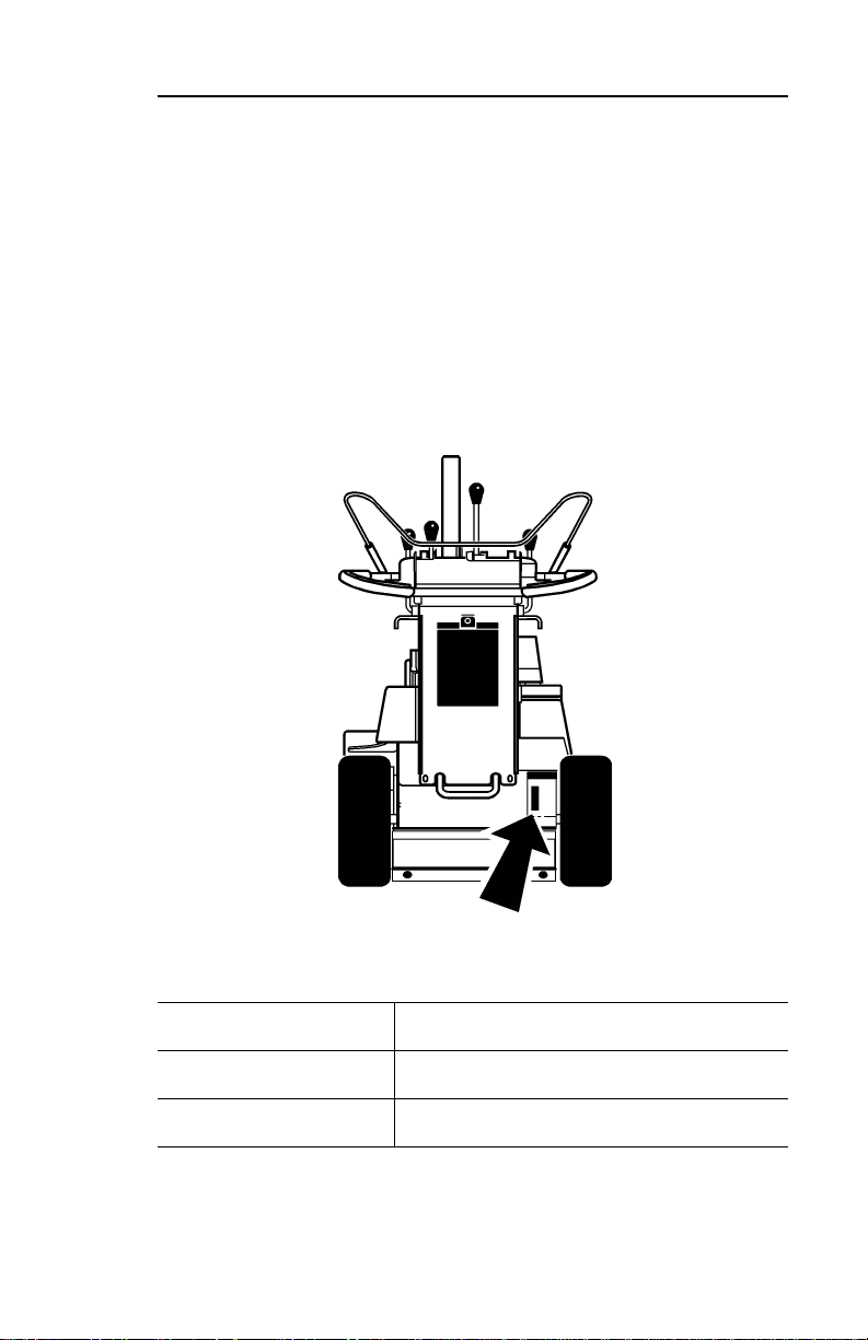
Record serial numbers and date of purchase in spaces pr ovided.
Serial number plate is mounted to frame behind right wheel.
Date of purchase
Serial number
Engine serial number

2 1030/1230 - SERVICE
SUPPORT PROCEDURE
SUPPORT PROCEDURE
Notify your dealer immediately of any malfunction or failure of
Ditch Witch equipment.
Always give model, serial number, and approximate date of
equipment purchase. This information should be recorded and
placed on file by owner at time of purchase.
Return damaged parts to dealer for inspection and warranty
consideration.
Order genuine Ditch Witch replacement parts from your
authorized Ditch Witch dealer. Use of another manufacturer’s
parts may void warranty.
RESOURCES
Publications
Contact your Ditch Witch dealer for publications covering
operation, service, and repair of your equipment.
Ditch Witch Training
For information about on-site, individualized training, contact yo ur
Ditch Witch dealer.

1030/1230 - FOREWORD 3
FOREWORD
This manual is an important part of your equipment. It provides
safety information and operation instructions to help you use and
maintain your Ditch Witch equipment.
Read this manual before using your equipment. Keep it with the
equipment at all times for future reference. If you sell your
equipment, be sure to give this manual to the new owner.
If you need a replacement copy, contact your Ditch Witch dealer.
If you need assistance in locating a dealer, visit our website at
www.ditchwitch.com or write to the following address:
The Charles Machine Works, Inc.
Attn: Marketing Department
PO Box 66
Perry, OK 73077-0066
USA
The descriptions and specifications in this manu al are su bje c t to
change. The Charles Machine Works, Inc. reserves the right to
improve equipment. Some product improvements may have
taken place after this manual was published. For the latest
information on Ditch Witch equipment, see your Ditch Witch
dealer.
Thank you for buying and using Ditch Witch equipment.

4 1030/1230 - FOREWORD
Operator's Manual
Issue Number 4.2/OP-11/04
Part Number 054-515
Copyright 1997, 1999, 2001, 2003, 2004
by The Charles Machine Works, Inc.,
Perry, Oklahoma
, Ditch Witch, CMW, AutoCrowd,
Modularmatic, Jet Trac, Roto Witch, Subsite, Fluid Miser, PermaSoil, Power Pipe, Super Witch, Super Witch II, Pierce Airrow, The
Underground, and The Underground Authority Worldwide are
registered trademarks of The Charles Machine Works, Inc.

1030/1230 - CONTENTS 5
CONTENTS
SERVICE . . . . . . . . . . . . . . . . . . . . . . . . . . . . . . . . . . . . . . .1
Serial Number Record . . . . . . . . . . . . . . . . . . . . . . . . .1
Support Procedure . . . . . . . . . . . . . . . . . . . . . . . . . . . . 2
Resources . . . . . . . . . . . . . . . . . . . . . . . . . . . . . . . . . .2
FOREWORD . . . . . . . . . . . . . . . . . . . . . . . . . . . . . . . . . . . . 3
OVERVIEW . . . . . . . . . . . . . . . . . . . . . . . . . . . . . . . . . . . . . 7
CONTROLS . . . . . . . . . . . . . . . . . . . . . . . . . . . . . . . . . . . . . 9
Control Console Overview . . . . . . . . . . . . . . . . . . . . . .9
Control Console Descriptions . . . . . . . . . . . . . . . . . . . 10
Engine Controls Overview. . . . . . . . . . . . . . . . . . . . . .13
Engine Controls Descriptions . . . . . . . . . . . . . . . . . . . 14
SAFETY . . . . . . . . . . . . . . . . . . . . . . . . . . . . . . . . . . . . . . . 15
Accessories . . . . . . . . . . . . . . . . . . . . . . . . . . . . . . . .16
Underground Hazards . . . . . . . . . . . . . . . . . . . . . . . .16
Emergency Procedures . . . . . . . . . . . . . . . . . . . . . . .17
Jobsite Classification . . . . . . . . . . . . . . . . . . . . . . . . .20
Safety Alert Classifications . . . . . . . . . . . . . . . . . . . . .24
Safety Alerts . . . . . . . . . . . . . . . . . . . . . . . . . . . . . . . .25

6 1030/1230 - CONTENTS
TRANSPORTATION . . . . . . . . . . . . . . . . . . . . . . . . . . . . 31
Lift . . . . . . . . . . . . . . . . . . . . . . . . . . . . . . . . . . . . . . . 31
Tiedown . . . . . . . . . . . . . . . . . . . . . . . . . . . . . . . . . . . 33
Haul . . . . . . . . . . . . . . . . . . . . . . . . . . . . . . . . . . . . . . 35
Freewheel . . . . . . . . . . . . . . . . . . . . . . . . . . . . . . . . . 37
Tow . . . . . . . . . . . . . . . . . . . . . . . . . . . . . . . . . . . . . . 38
OPERATION . . . . . . . . . . . . . . . . . . . . . . . . . . . . . . . . . . . 39
Daily Inspection . . . . . . . . . . . . . . . . . . . . . . . . . . . . . 39
Startup . . . . . . . . . . . . . . . . . . . . . . . . . . . . . . . . . . . . 40
Driving . . . . . . . . . . . . . . . . . . . . . . . . . . . . . . . . . . . . 42
Trenching. . . . . . . . . . . . . . . . . . . . . . . . . . . . . . . . . . 43
LUBRICATION AND MAINTENANCE. . . . . . . . . . . . . . . 47
Lubrication Overview . . . . . . . . . . . . . . . . . . . . . . . . . 48
Lubrication Schedule . . . . . . . . . . . . . . . . . . . . . . . . . 49
Maintenance Schedule. . . . . . . . . . . . . . . . . . . . . . . . 56
SPECIFICATIONS . . . . . . . . . . . . . . . . . . . . . . . . . . . . . . 61
1030 . . . . . . . . . . . . . . . . . . . . . . . . . . . . . . . . . . . . . 61
1230. . . . . . . . . . . . . . . . . . . . . . . . . . . . . . . . . . . . . . 64

1030/1230 - OVERVIEW 7
OVERVIEW
The Ditch Witch 1030 and 1230 pedestrian trenchers are
designed for easy, efficient use.
Color-coded controls are within easy reach of the operator.
These compact units fit through most standard yard gates, and
the machines are balanced for easy jobsite maneuvering. A
choice of a 24”, 30”, or 36” (610-, 760-, or 915-mm) digging
boom, along with several chain options, make these machines
flexible enough for most soil conditions. The axle lock feature
aids smooth, easy turns and straight trenching.
1. Trail wheel
2. Digging boom and chain
3. Engine
4. Operator station

8 1030/1230 - OVERVIEW

1030/1230 - CONTROLS 9
CONTROL CONSOLE OVERVIEW
CONTROLS
CONTROL CONSOLE OVERVIEW
1. Bail
2. Digging boom control (green)
3. Axle lock (blue)
4. Speed/direction control (orange)
5. Throttle (black)
6. Digging chain control (yellow)
7. Power switch
10 1030/1230 - CONTROLS
CONTROL CONSOLE DESCRIPTIONS
CONTROL CONSOLE DESCRIPTIONS
Bail
This start interlock control engages and disengages hydraulic
system.
• Move down into handlebar to engage.
• Release to disengage.
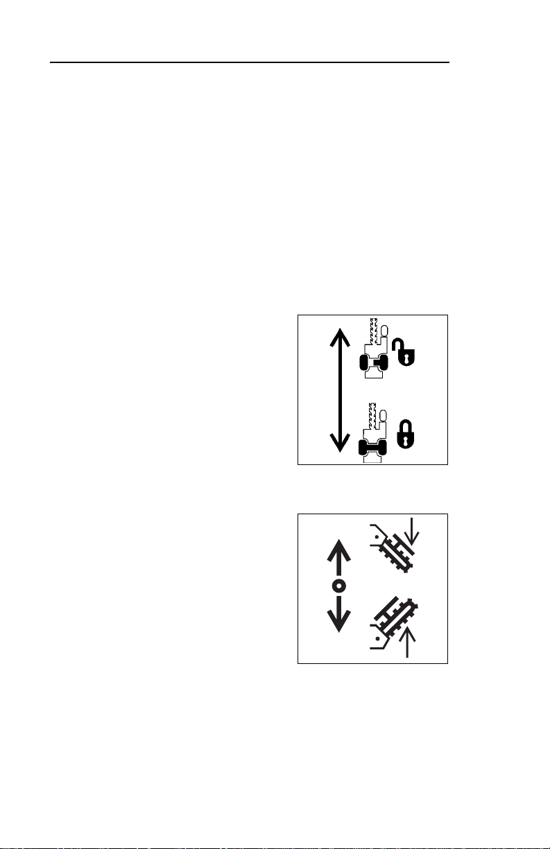
Axle Lock (Blue)
This lever locks or unlocks axle.
• Push to unlock. Use unlocked
axle to manuever trencher.
• Pull to lock. Use locked axle
for straight trenching and
driving over rough terrain.
ic1034.tif
Digging Boom Control (Green)
This lever raises or lowers digging
boom when bail is engaged.
• Push to lower boom.
• Pull to raise boom.
ic0127h.eps

1030/1230 - CONTROLS 11
CONTROL CONSOLE DESCRIPTIONS
Digging Chain Control (Yellow)
This lever starts digging chain
when bail is engaged.
• Push to start digging chain.
• Returns to neutral and digging
chain stops when bail is
released.
ic0014c.tif
Speed/Direction Control
(Orange)
This lever controls unit speed and
direction when bail is engaged.
• Ensure control is in BAIL
RELEASE (neutral) position,
and engage bail.
• Push to move forward.
ic0013c.tif
• Pull to move backward.
• Move farther from center to go faster in either direction.
• Return to BAIL RELEASE (neutral) to stop.

12 1030/1230 - CONTROLS
CONTROL CONSOLE DESCRIPTIONS
Throttle (Black)
This lever controls engine speed.
Increasing engine speed also
increases digging chain speed.
• Push down to speed engine.
• Pull up to slow engine.
ic0128h.eps
Power Switch
This two-position switch controls power to the ma ch in e.
• Turn clockwise to turn power on. In this position, engine will
start when rope start is pulled.
• Turn counterclockwise to stop engine.
1030/1230 - CONTROLS 13
ENGINE CONTROLS OVERVIEW
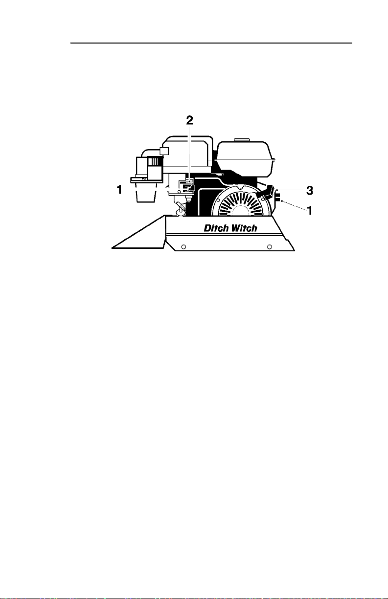
ENGINE CONTROLS OVERVIEW
1. Fuel shut-off valves
2. Choke
3. Pull start

14 1030/1230 - CONTROLS
ENGINE CONTROLS DESCRIPTIONS
ENGINE CONTROLS DESCRIPTIONS
Fuel Shut-off Valves
Two valves separate fuel reservoir from engine.
• Close when transporting unit to or from jobsite.
• Open before starting engine.
Choke
This valve regulates air/fuel mixture. Close valve to help start cold
engine.
Pull Start
Cranks engine for starting.
• Ensure that power switch is on and fuel shut-off valves are
open.
• Pull to start engine.
If engine does not start after three pulls, turn power switch off and
check for fuel blockage or electrical system problems.

1030/1230 - SAFETY 15
SAFETY
Follow these guidelines before operating any jobsite equipment:
• Complete proper training and read operator’s manual before
using equipment.
• Contact One-Call (888-258-0808) and any utility companies
which do not subscribe to One-Call. Have all underground
pipes and cables located and marked before operating
equipment. If you damage a utility, contact utility company.
• Classify jobsite based on its hazards and use correct tools
and machinery, safety equipment, and work methods for
jobsite.
• Mark jobsite clearly and keep spectators away.
• Wear personal protective equipment.
• Review jobsite hazards, safety and emergency procedures,
and individual responsibilities with all personnel before work
begins. Safety videos are available from your Ditch Witch
dealer.
• Replace missing or damaged safety shields and safety signs.
• Use equipment carefully. Stop oper ation and investigate
anything that does not look or feel right.
• Do not operate unit where flammable gas is present.
• Contact your Ditch Witch dealer if you have any question
about operation, maintenance, or equipment use.

16 1030/1230 - SAFETY
ACCESSORIES
ACCESSORIES
Fire Extinguisher
If required, a fire extinguisher should be mounted near the power
unit but away from possible points of ignition. The fire
extinguisher should always be classified for both oil and electric
fires. It should meet legal and regulatory requirements.
Lighting Kit
If you need additional light, plug lighting kit into provided outlet.
Contact your Ditch Witch dealer for further information.
UNDERGROUND HAZARDS
Striking underground hazards can cause explosion, electrocution,
fire, and exposure to hazardous materials.
Hazards include:
• Electric lines
• Natural gas lines
• Fiber optic cables
• Water lines
• Sewer lines
• Pipes carrying other chemicals, liquids, or ga se s
• Storage tanks

1030/1230 - SAFETY 17
EMERGENCY PROCEDURES
EMERGENCY PROCEDURES
Before operating any equipment, review emergency procedures
and check that all safety precautions have been taken.
EMERGENCY SHUTDOWN - Turn ignition switch to stop position
or push remote engine stop button.
Electric Strike Description
When working near electric cables, remember the following:
• Electricity follows all paths to ground, not just path of least
resistance.
• Pipes, hoses, and cables will conduct electricity back to all
equipment.
• Low voltage current can injure or kill. Almost one-third of
work-related electrocutions result from contact with less than
440 volts.
Most electric strikes are not noticeable, but indications of a strike
include:
• power outage
•smoke
•explosion
• popping noises
• arcing electricity
If any of these occur, assume an electric strike has occ urred.

18 1030/1230 - SAFETY
EMERGENCY PROCEDURES
If an Electric Line is Damaged
If you suspect an electric line has been damaged and you are on
tractor, DO NOT MOVE. Remain on tractor and take the
following actions. The order and degree of action will depend
upon the situation.
• Warn people nearby that an electric strike has occurred.
Instruct them to leave the area and contact utility.
• Raise attachments and drive from immediate area.
• Contact utility company to shut off power.
• Do not return to jobsite or allow anyone into area until given
permission by utility company.
If you suspect an electric line has been damaged and you are off
tractor, DO NOT TOUCH TRACTOR. Take the following actions.
The order and degree of action will depend upon the situation.
• LEAVE AREA.
• Contact utility company to shut off power.
• Do not return to jobsite or allow anyone into area until given
permission by utility company.

1030/1230 - SAFETY 19
EMERGENCY PROCEDURES
If a Gas Line is Damaged
If you suspect a gas line has been damaged, take the following
actions. The order and degree of action will depend on the
situation.
• Immediately shut off engine(s), if this can be done safely and
quickly.
• Remove any ignition source(s), if this can be done safely and
quickly.
• Warn others that a gas line has been cut and that they should
leave the area.
• Leave jobsite as quickly as possible.
• Immediately call your local emergency phone number and
utility company.
• If jobsite is along street, stop traffic from driving near jobsite.
• Do not return to jobsite until given permission by emergency
personnel and utility company.
If a Fiber Optic Cable is Damaged
Do not look into cut ends of fiber optic or unidentified cable.
Vision damage can occur.
If Machine Catches on Fire
Perform emergency shutdown procedure and then take the
following actions. The order and degree of action will depend on
the situation.
• Immediately move battery disconnect switch (if equipped) to
disconnect position.
• If fire is small and fire extinguisher is available, attempt to
extinguish fire.
• If fire cannot be extinguished, leave area as quickly as
possible and contact emergency personnel.

20 1030/1230 - SAFETY
JOBSITE CLASSIFICATION
JOBSITE CLASSIFICATION
Inspecting Jobsite
• Follow U.S. Department of Labor regulations on excavating
and trenching (Part 1926, Subpart P) and other similar
regulations.
• Contact One-Call (888-258-0808) and any utility companies
which do not subscribe to One-Call.
• Inspect jobsite and perimeter for evidence of underground
hazards, such as:
– “Buried utility” notices
– Utility facilities without overhead lines
– Gas or water meters
– Junction boxes
– Drop boxes
– Light poles
– Manhole covers
– Sunken ground
• Have an experienced locating equipment operator sweep
area within 20’ (6 m) to each side of trench path. Verify
previously marked line and cable locations.
• Mark location of all buried utilities and obstructions.
• Classify jobsite.

1030/1230 - SAFETY 21
JOBSITE CLASSIFICATION
Selecting a Classification
Jobsites are classified according to underground hazards
present.
If working . . . then classify jobsite as . . .
within 10’ (3 m) of a buried
electric
electric line
within 10’ (3 m) of a natural
natural gas
gas line
in sand, granite, or concrete
crystalline silica (quartz) dust
which is capable of producing
crystalline silica (quartz) dust
within 10’ (3 m) of any other
other
hazard
NOTICE: If you have any doubt about jobsite classification, or if
jobsite might contain unmarked hazards, take steps outlined
previously to identify hazards and classify jobsite before working.

22 1030/1230 - SAFETY
JOBSITE CLASSIFICATION
Applying Precautions
Once classified, precautions appropriate for jobsite must be
taken.
Electric Jobsite Precautions
Use one or both of these methods.
• Expose line by careful hand digging or soft excavation.
• Have service shut down while work is in progress. Have
electric company test lines before returning them to service.
Natural Gas Jobsite Precautions
In addition to positioning equipment upwind from gas lines, use
one or both of these methods.
• Expose lines by careful hand digging or soft excavation.
• Have gas shut off while work is in progress. Have gas
company test lines before returning them to service.
 Loading...