


Starlight MPA Bullet Camera
DWC-B5661TIR
DWC-B5661TIR550
ABOUT MANUAL
Before installing and using the camera, please read this manual carefully. Be sure to keep it handy for future reference.
06252014
PRECAUTIONS
Do not open or modify.
Do not open the case except during maintenance and installation, for it may be dangerous and can cause damages.
Do not put objects into the unit.
Keep metal objects and flammable substances from entering the camera. It can cause fire, short-circuits, or other damages.
Be careful when handling the unit.
To prevent damages, do not drop the camera or subject it to shock or vibration. Do not install near electric or magnetic fields.
Protect from humidity and dust. Protect from high temperature.
Be careful when installing near the ceiling of a kitchen or a boiler room, as the temperature may rise to high levels.
Cleaning:
To remove dirt from the case, moisten a soft cloth wi h a soft detergent solution and wipe. Mounting Surface:
The material of the mounting surface must be strong enough to support the camera.
FCC COMPLIANCE
This equipment has been tested and found to comply with the limits for a Class B digital device, pursuant to part 15 of the FCC rules. These limits are designed to provide reasonable protection against harmful interference, when the equipment is operated in a residen ial environment. This equipment generates, uses, and radiates radio frequency energy; and if it is not installed and used in accordance with the instruction manual, it may cause harmful interference to radio communications.
WARNING: Changes or modifications are not expressly approved by the manufacturer.
2

TABLE OF CONTENTS
Introduction |
Features |
4 |
|
Parts and Descriptions |
5 |
|
Dimensions |
6-7 |
Installation |
Inside the Box |
8 |
|
Mount Installation Instructions |
9 |
|
Connecting to Monitors |
10 |
|
Control Board |
11 |
|
Adjus ing the Camera Angle |
12 |
Module OSD Menu |
|
13-25 |
Troubleshooting |
|
26 |
Warranty Information |
|
27-28 |
Specifications |
|
29-30 |
3

FEATURES*
1/3" Sony 1.3M CMOS
820 TV Lines [B/W], 800 TV Lines [Color]
2.8~12mm Varifocal Auto Iris Lens [DWC-B5661TIR Model]
5~50mm Varifocal Auto Iris Lens [DWC-B5661TIR550 Model]
100ft Range IR with Intelligent Camera Sync, Smart IR [DWC-B5661TIR Model] 150ft Range IR with Intelligent Camera Sync, Smart IR [DWC-B5661TIR550 Model] True Day & Night with IR Cut Filter
3D DNR (3D Digital Noise Reduction) WDR (Wide Dynamic Range)
Star-Light (Super Low Light Technology) HME (Highlight Masking Exposure)
Defog (Extreme Weather Image Compensation) Digital Quick Zoom & 8x Digital Zoom
16:9 and 4:3 Viewing Modes AGC / BLC / AWB
Privacy Zones (16) & 4 Motion Detection Zones Camera Control via RS-485/ UTC
Secondary BNC Output
RS485, UTP, & 1 Alarm Output Built-In IP66 Certified (Weatherproof)
4

PARTS & DESCRIPTION* |
12 |
|||
|
|
|
|
11 |
|
4 |
|
3 |
10 |
|
|
|
|
|
|
|
|
|
9 |
|
5 |
|
|
|
|
6 |
|
|
8 |
|
|
|
|
|
|
|
|
|
1 |
|
|
|
2 |
|
|
|
|
|
7 |
1 |
Moun ing Bracket |
7 |
OSD Joystick Controller |
|
2 |
Camera Module |
8 |
BNC Cable |
|
3 |
Sunshield Adjusting Screws |
9 |
12VDC Power Outlet |
|
4 |
Sunshield Cover |
10 |
RS485 Cable |
|
5 |
IR Module |
11 |
UTP Cable |
|
6 |
Front Case |
12 |
Alarm Output Cable |
|
|
|
|
|
5 |
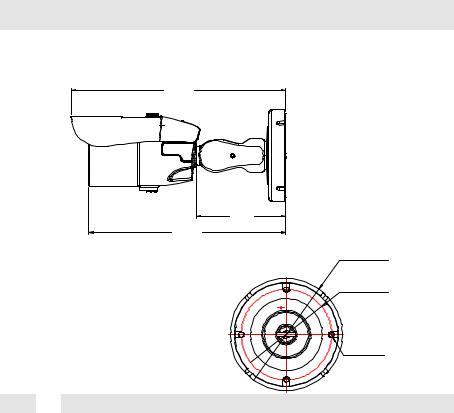
DIMENSIONS IN MILLIMETERS (IN)*
DWC-B5661TIR
224.5
(8.83”)
94.0
206.0 (3.7”) (8.11”)
 96.7 (3.8”)
 78.0 (3.07”)
 4.2 (0.16”)
6
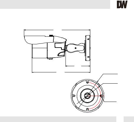
DIMENSIONS IN MILLIMETERS (IN)*
DWC-B5661TIR550
252.0
(9.9”)
93.5
(3.68”)
222.5
(8.76”)
 96.7 (3.8”)
 78.0 (3.07”)
 4.2 (0.16”)
7
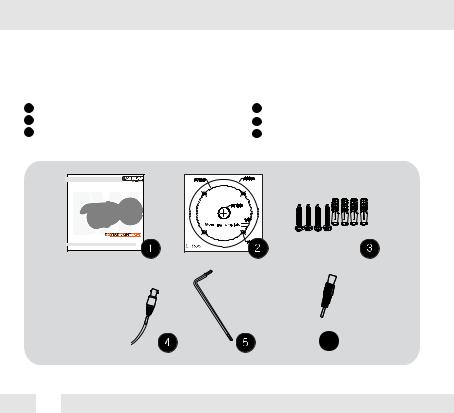
INSIDE THE BOX*
Included with Bullet Camera:
1User Manual
2Moun ing Template
34 Machine Screws and 4 Dry Wall Anchors
Starlight MPA Bullet Camera |
|
DWC-B566 T R |
|
DWC-B566 T R550 |
|
AB U MA A |
|
B |
|
B |
|
0 |
0 |
4Secondary Video-BNC Cable
5L-Key
6DC Plug Power Cable
 6
6
8
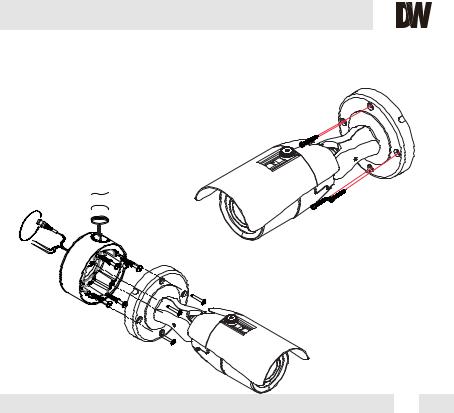
INSTALLATION INSTRUCTIONS*
1.Using the mounting template or your own camera, mark and drill the necessary holes to mount he
bracket to a wall or ceiling.
2. Pull all necessary wires through and make the proper connections.
3.Use the four (4) mounting screws to install the camera on the wall or ceiling.
 NPT 3/4” Pipe
*Installation Using a Junction Box
*Note: Electrical junction box and required screws sold separately.
9
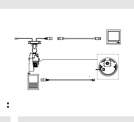
CONNECTING TO MONITORS*
Use the diagram below to connect to a Monitor or CRT Monitor properly.
12VDC/24VAC
|
CCTV Monitor |
|
Up |
Left |
Right |
Second Video Output |
Down |
|
Monitor
Power Connection - 12VDC/24VAC Dual Voltage (Auto Polarity Detection and Protection) All cameras are equipped with a second video output for on-site configuration.
10
 Loading...