


 Loading...
USER MANUAL
The picture might differ according to the specification and model.
Contents of this user manual are protected under copyrights and computer program laws. Rev: 04/19
Thank You!
Before operating the system, please read this User Manual and retain it for future reference.

WARNING
TO REDUCE FIRE OR SHOCK HAZARD,
DO NOT EXPOSE THE UNIT TO RAIN OR MOISTURE.
The installation should be made by a qualified service person and conformed to all local codes.
Cautions
Read Before System Operation
Follow these details to prevent material damage or personal injury.
Signs of Caution and Warning
 Warning: This sign indicates that the user could die or be seriously wounded if not used or installed properly.
 Caution: This sign indicates that the user could be wounded or could expect property damage if not used or installed properly.
 Warning: Do not expose the product to fog, rain or too much humid to decrease danger from electric shock or fire.
General Warning
 Warning
1.Use the power cord, which is supplied or recommended by the supplier, or it may cause fire.
2.Do not disassemble or reassemble the product. It may cause malfunction or fire.
3.Enquire to your vendor for repair. It may cause electric shock or fire if the repair is not done properly.
4.Do not touch the product with wet hands. It may cause malfunction or electric shock.
5.Product installation must be ensured to a professional for product installation, or it may cause malfunction, electric shock or fire.
6.Ground applies to video products equipped with a 3-wire grounding type plug having a third (grounding) pin. This plug only fits into a grounding-type power outlet. If grounding is not done, it may cause malfunction or electric shock.
7.Ground connection must not touch gas pipe, water pipe or telephone line. If grounding is not done properly, it may cause electric shock.
8.Prevent metallic foreign substance from going inside the product. It may cause malfunction or electric shock.
9.Do not spray insecticide or flammable spray while driving. It may cause fire.
10.Place the system in an open place where air ventilation is guaranteed, or it may cause overheating and seriously damage the system to be fired.
11.Prevent water from instilling inside electrical parts. Clean with a dry towel or malfunction or electric shock could result.
 Caution
1. Use the power cord, which is supplied or recommended by the supplier. The internal fan rotates at high speed and may cause an accident.

2.Do not drop, give strong vibration, or shock to the product. It may cause malfunction.
3.The air inhaler of the front panel and air outlet of the back panel must not be blocked during installation.
The internal temperature of the product would be greater than allowable and could cause malfunction or fire.
4.Do not touch the product or the power cord when there is thunder. It may cause electric shock.
5.Do not install the product near or on top of heating source. The internal temperature of the product would be greater than allowable and could cause malfunction or fire.
6.Do not install the product on inclined or unstable location or where vibration could be committed. It may cause malfunction.
Cautions about the Power
 Warning
1.Must use the outlet of the grounding to connect the power cord, or it may cause fire.
2.Do not connect on the middle of power cord or use extension cord. It may generate heat or cause fire.
3.Do not touch the power cord with wet hands. It may cause electric shock.
4.Keep power cord dry and protect from humidity. It may generate heat or cause fire. The power cord is not waterproof.
5.Hold the body of the plug while removing the power plug. Do not pull the power cord. Damage to the power cord may generate heat or cause fire.
6.Check the power plug regularly. Humidity and moderation in smoking may cause fire.
7.Remove power cord from outlet when product is not used for a long time. It may cause shortcircuit or electric shock.
 Caution
1.Do not turn off the power by removal of the power plug. To turn off the power, click the power button from the front panel. When the system stops abnormally, the power button might not work. Click power button for 5 full seconds to turn power off.
2.Do not cut off the power artificially, or give shock or vibration to unit while the hard disk is activating. It may cause hard disk failure or loss of data.
 Remarks
Pictures and buttons are subject to be changed or modified up to different models.
Function or configuration is subject to be changed or modified without prior notice for improvement of the product.

1 VMAX A1 Plus™ DVR |
|
|
Table of Contents |
|
|
1. |
GETTING STARTED................................................................................................................................ |
2 |
1.1 |
CHECKING SUPPLIED ITEMS ..................................................................................................................................... |
2 |
1.2 |
SYSTEM SETUP........................................................................................................................................................... |
3 |
1.3 |
SYSTEM SHUTDOWN ................................................................................................................................................. |
4 |
1.4 |
SYSTEM EXPLANATION ............................................................................................................................................. |
5 |
2. |
STARTUP WIZARD ................................................................................................................................. |
9 |
2.1 |
LANGUAGE ................................................................................................................................................................. |
9 |
2.2 |
NETWORK................................................................................................................................................................... |
9 |
2.3 |
NAME AND TIME ZONE........................................................................................................................................... |
12 |
2.4 |
CAMERA CONNECTION........................................................................................................................................... |
12 |
2.5 |
PRODUCTION REGISTRATION................................................................................................................................. |
13 |
2.6 |
FIRMWARE UPGRADE ............................................................................................................................................. |
13 |
2.7 |
FINISH ....................................................................................................................................................................... |
13 |
3. |
OPERATION............................................................................................................................................. |
14 |
3.1 |
USER LOG-IN ........................................................................................................................................................... |
14 |
3.2 |
LIVE DISPLAY MODE............................................................................................................................................... |
14 |
3.3 |
PTZ OPERATION..................................................................................................................................................... |
17 |
3.4 |
PLAYBACK RECORDED IMAGES ............................................................................................................................. |
18 |
3.5 |
SEARCH RECORDED IMAGE ................................................................................................................................... |
19 |
3.6 |
DST SETTING AND IMAGE PLAYBACK................................................................................................................. |
23 |
4. |
SETTING .................................................................................................................................................. |
25 |
4.1 |
SYSTEM .................................................................................................................................................................... |
26 |
4.2 |
DEVICE..................................................................................................................................................................... |
32 |
4.3 |
ALARM ..................................................................................................................................................................... |
39 |
4.4 |
RECORD................................................................................................................................................................... |
42 |
4.5 |
NETWORK................................................................................................................................................................ |
45 |
4.6 |
EXPORT .................................................................................................................................................................... |
51 |
5. WEB SURVEILLANCE THROUGH INTERNET EXPLORER ....................................................... |
54 |
|
5.1 |
WEB LOGIN............................................................................................................................................................. |
54 |
5.2 |
WEB MONITORING................................................................................................................................................. |
54 |
5.3 |
WEB PLAYBACK ..................................................................................................................................................... |
55 |
5.4 |
DVR’S SETUP FROM THE WEB VIEWER .............................................................................................................. |
57 |
6. |
Q & A ........................................................................................................................................................ |
58 |
7. |
SPECIFICATIONS ................................................................................................................................. |
60 |
User Manual 2
1. Getting Started
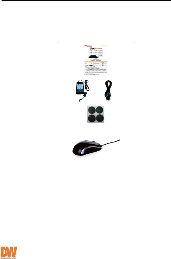
1.1Checking Supplied Items
Make sure that you have the following items supplied with your DVR. If any of these items is missing or damaged, notify your vendor immediately. Keep the packing utilities for moving or storage purposes.
Items |
Photo |
Quantity |
|
Quick start guide and |
|
|
|
download instruction card |
|
1 |
|
|
|
|
|
12V D/C adaptor and power |
|
1 set |
|
cable |
|
||
|
|
||
|
|
|
|
Rubber mount* |
|
1 set (4 Pieces) |
|
|
*Included contents may differ |
|
|
|
depending on the DVR model |
|
|
USB mouse |
|
1 |
|
|
|
|
3 VMAX A1 Plus™ DVR
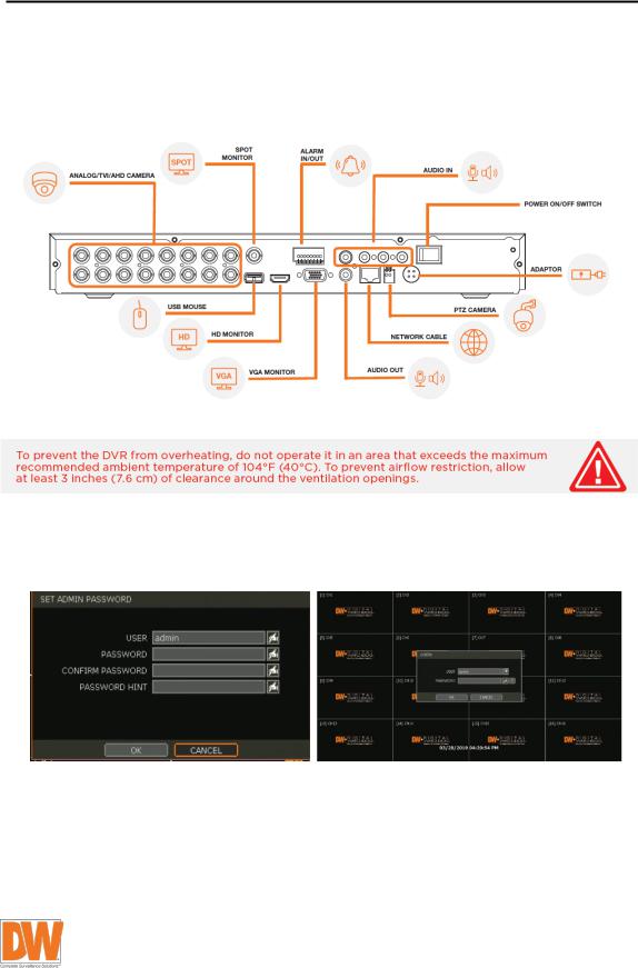
1.2System Setup
1.2.1. Connect External Devices
Follow the diagram below to connect all necessary external devices to your DVR. Please note that the number of ports available may differ based on the model. See product’s specifications at the end of the manual for more information.
1.2.2. System Startup
After connecting all external devices to the DVR, power up the DVR by connecting 12V adaptor/ power cable to the power jack on the rear panel. The boot logo will display. Please wait until the boot process completes.
When the system starts, the PASSWORD CHANGE window will be displayed. User can set the password for any available user. Or click “cancel” to keep the default password as empty (no password). To login, right-click anywhere on the screen and enter the username and password in the popup screen (default admin username / password: admin / no password). There is only one administrator account configurable in the DVR. It is assigned with an unchangeable user ID marked as “admin”. The default password is empty (no password). Administrator account has full access to the DVR and its configurable parameters and can also create new users and assign rights to new user accounts.
User Manual 4
If the DVR is set to AUTO LOGIN, login process is not necessary.
NOTE |
1) If the network configuration is set to DHCP mode but there is no DHCP |
|
server in the network or the network is not connected it may take a few |
||
|
||
|
minutes to start the system after turning on the power. |
2)The mouse is included with the DVR. In case you need to replace it, it is highly recommended to choose from well-known major brands such as DELL, MICROSOFT, LOGITECH, or HP.
3)Do not forget the administrator’s password that was set for the first time. In case the password is forgotten, contact your local dealer for help.
4)Refer to section 4.1.2 User for AUTO LOGIN and AUTO LOGOFF.
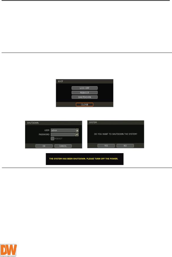
1.3System Shutdown
To turn the DVR’s power off, click the exit button [ ] on the tool bar and [SHUTDOWN] in the pop-up screen as below. Do not turn off the power by unplugging the power plug.
Enter the password and click [OK] to shut down the system. Click [YES] to confirm and turn the OFF button on the back side of the device for complete shutdown.
NOTE |
User can input password by virtual keyboard or IR remote-control (if available). |
|
|
5 | VMAX A1 Plus™ DVR
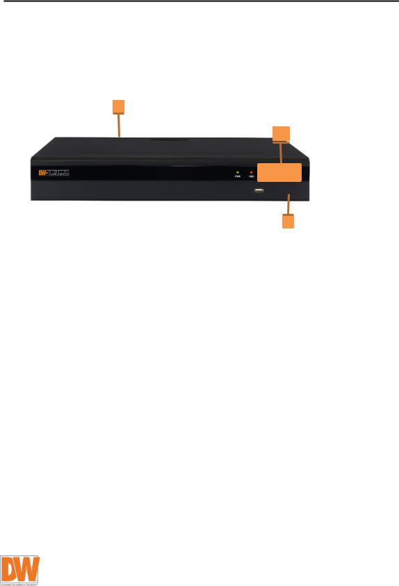
1.4 System Explanation
1.4.1. Front Panel
** Front panel may differ according to the model.
1.4.2.Power: System ON/OFF
1.Power button (On the back side)
2.LED indicator: indicates system status for power, record and network status.
3.USB port: for backup and upgrade.

User Manual | 6
1.4.3. IR Remote Controller (Optional Item)
|
16 |
|
1 |
2 |
|
17 |
15 |
|
8 |
4 |
|
9 |
10 |
|
11 |
12 |
|
6 |
5 |
|
7 |
||
14 |
||
|
||
13 |
|
|
3 |
|
•Power: system ON/OFF
•DVR ID selection
•Numeric button: channel selection or password input
•PTZ button
•Preset button: select preset in PTZ mode
•Focus button: focus IN/OUT in PTZ mode
•ZOOM button: zoom IN/OUT in PTZ mode
•Preset tour: tour ON/OFF in PTZ mode
•Direction button
•Enter button
•Menu button
•Return button
•Playback buttons on search mode
•Emergency recording button
•Auto-sequence button in live mode
•Screen mode button
•Backup button
User can control multiple DVRs with one IR remote controller.
NOTE In order to control multiple DVRs, each DVR must have a different remote ID. (The default ID is set as “0”.)
To setup the ID # in IR remote controller:
1)Keep pressing ID selection button () for about 5 seconds.
2)Set the ID number by pressing numeric button on IR remote controller. ID number is available from 000 up to 255.
3)You have to press numeric button as three-digit number format. For example, press “000” for 0, “023” for 23, and “234” for 234.
7 | VMAX A1 Plus™ DVR
1.4.4. Tool Bar in Live Mode
In live view, move the mouse cursor to the bottom of the screen to show the menu bar.
• Menu: click on the menu button to access the DVR’s main menu screen. See section 4. Setting.
•


 Display mode: select the display split mode from the available options. Select 1CH, 4CH, 9CH or 16CH mode. Available options may differ based on the model.
• Sequence: start and stop sequence mode in live mode. Sequence is disabled if all channels are displayed.
• Channel number: switch to single channel view of a specific channel by pressing the corresponding number.
• Emergency recording: the system records all channels with full frame rate at the maximum resolution regardless of recording setting. To stop emergency recording, click the same icon again.
• Export: backup recorded video to an external device. See section 4.6 Export.
• Playback: switch to playback mode. See section 3.4 Playback Recorded Image.
• Search: open the search options screen. See section 3.5 Search Recorded Image.
• Exit: exit the DVR with three different options: log off, reboot and shutdown.
• Pin: when selected, the DVR’s menu bar will be displayed on the screen permanently, regardless of the mouse’s position.

User Manual | 8
1.4.5. Tool Bar in Playback Mode
In Playback view, move the mouse cursor to the bottom of the screen to show the menu bar.
• Channel: indicates the currently selected channel.
• |
Intelligent search bar: shows |
|
recording status for the selected channel from 00:00 to 24:00 hours. A white-vertical |
|
line indicates the time currently displayed. Moving the white-vertical line will update the |
|
video shown. |
•
 Previous / next date search: Move to a previous date or the next date to search.
•Playback controls:
• : Playback speed control. (X32 / x16 / x8 / x4 / x2).
• : Move backward one frame
• : Stop button
• : Play button
• : Move forward one frame
• : Playback speed control. (X2 / x4 / x8 / x16 / x32)
• : Current playback speed
• Screen display mode: select the display split mode from the available options. Select 1CH, 4CH, 6CH, 9CH, 10CH, 13CH or 16CH mode. Available options may differ based on the model.
• Export: backup recorded video to an external device. See section 4.6 Export.
• Playback: switch to playback mode. See section 3.4 Playback Recorded Image.
• Exit: close playback mode and move to live mode.
• Pin: when selected, the DVR’s menu bar will be displayed on the screen permanently, regardless of the mouse’s position.
9 | VMAX A1 Plus™ DVR
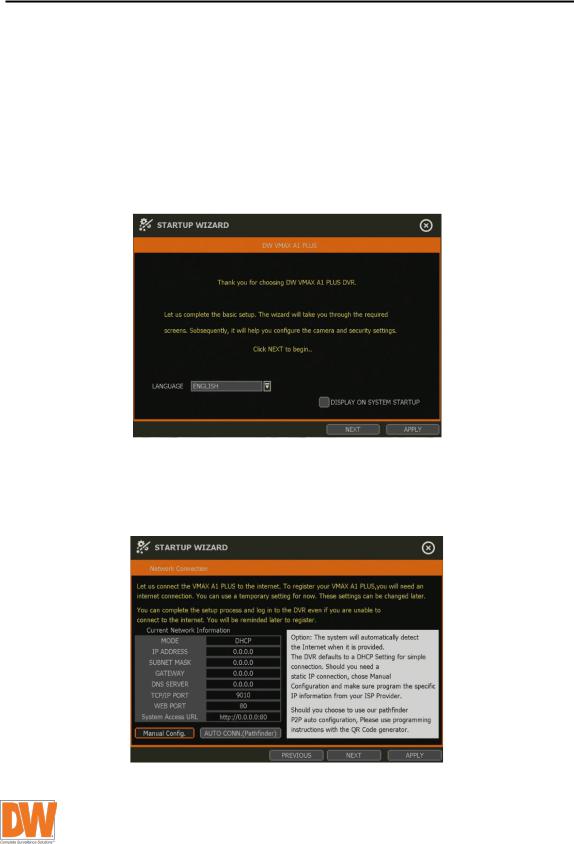
2. Startup Wizard
When the DVR is launched for the first time, the STARTUP WIZARD will appear. This wizard helps you setup the DVR’s most basic settings for proper functioning. You can access the startup wizard any time by clicking the startup wizard [ ] button in MENU > SYSTEM > SETTINGS. (See section 4.1.5 Settings).
2.1Language
Select the language according to the country or user’s preference.
If “DISPLAY ON SYSTEM STARTUP” is selected, startup wizard will pop up every time the system is started.
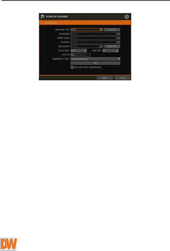
2.2Network
Setup the DVR’s network settings for remote connection. You can select to manually configure the DVR’s network settings (Manual Config.). You can also allow the system to setup the network settings automatically by selecting AUTO CONN. (Pathfinder™).
User Manual | 10
If Manual Config. has been selected, setup the information below:
•NETWORK TYPE: Select either STATIC IP or DHCP for dynamic IP.
If DHCP is selected, the DVR will automatically configure the network settings according to the current network requirements. If DHCP is selected, click “IP DETECT” button to detect automatically all the network settings.
If Static IP is selected, manually enter all necessary network settings. For proper configuration, it is recommended to assign the DVR a DHCP address and let it auto discover all the proper network settings, and then change the Network Type back to Static IP and save the changes
•IP ADDRESS: Displays the DVR’s IP address. If DHCP is selected, the IP address will automatically adjust to match the network’s requirements. You can also manually change the IP address as needed.
•SUBNET MASK: Subnet Mask address classifies the subnet that the system belongs to. For more information, please consult your network administrator or your internet provider.
•GATEWAY: This is the IP address of the router or gateway server. It is required when connecting to the DVR through the external router over the internet (from another network). For more information, consult your network administrator or your internet provider.
•DNS SERVER: Enter the IP address of the Domain Name Server. You should input the DNS Server information in order to use DDNS, E-mail notifications and NTP Server. For more information, please consult your network administrator or your internet provider.
•TCP/IP PORT: Input the port number to use when connecting to the DVR locally or remotely. Default is 9010.
If your ISP blocks the port # 9010, you need to input another validport number (ex, 9020).
•WEB PORT: Input the port number to use when connecting from the Web Browser. Default is 80. If your ISP blocks the port # 80, you need to input another valid web port number (ex, 8080).
•AUTO IP: Displays the system IP which is assigned through Auto-IP, automatically.
•BANDWIDTH LIMIT: Depending on the setting made by user, the system can control the data volume transmitted over network ranging from 25 kbps up to 1Gbps. This function is effective especially under narrow bandwidth network condition or when user wants to limit “network bandwidth occupied by video transmission” to a certain level. Default is 100 Mbps
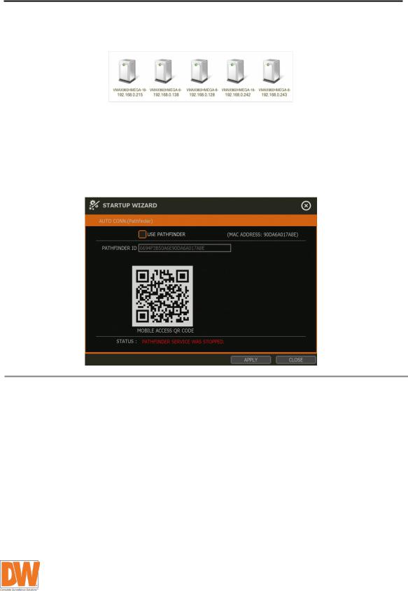
•USE UPnP (Universal Plug and Play): UPnP is a plug-and-play feature that allows the DVR to be automatically discovered by a PC on the same network. To locate the DVR,
11 | VMAX A1 Plus™ DVR
go to “My Network” on your PC. The computer will scan your network for all supported devices. The first five characters of the file name of a detected DVR represent the model number, followed by the DVR’s IP address
Once the PC discovered the DVR, double click on the icon to open the DVR’s web client. Enter your User ID and Password to login and click “Connect” to connect.
NOTE |
• The maximum number of simultaneous connection is 10 users. |
|
• For the other network settings, such as DDNS, Notification, Mobile Push & P2P |
||
|
||
|
Cloud, please see section 4.5 Network. |
If Auto connection (Pathfinder) has been selected, connect the DVR to the network by using the Pathfinder™ system. The DVR can be configured using the QR code.
NOTE |
• For more information, please see section 4.5.5 Pathfinder™. |
|
|
User Manual | 12
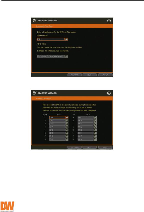
2.3Name and Time Zone
Set the DVR’s name and select the time zone.
2.4Camera Connection
Enter a camera name for each channel of the DVR according to the cameras connected.
13 | VMAX A1 Plus™ DVR
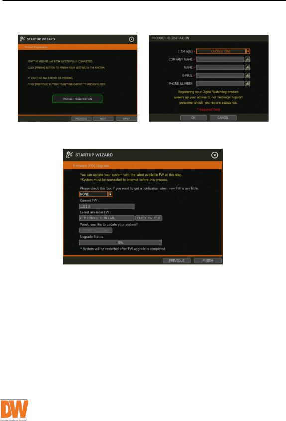
2.5Production Registration
Register the DVR and user information for technical support
2.6Firmware Upgrade
Upgrade the DVR’s firmware by network
2.7Finish
When the Setup Wizard is completed, click “FINISH” to close the wizard and go to the live view screen.

User Manual | 14
3. Operation
3.1User Log-in
Input USER and PASSWORD after turning on the system. The factory default of USER and PASSWORD are “admin” and no password.
NOTE 1) |
LOGIN window will be permanently displayed until a user logs in with the right |
|
USER and password. |
2) |
If DVR is set as AUTO LOGIN, login process is not necessary. See “4.1.2 User” for |
|
more information. |
NOTE The  key in the virtual keyboard includes common words, such as Admin, root, http://, rtsp://, www., .com, .net, .org etc.
3.2Live Display Mode
3.2.1. Channel Selection
Live image can be seen by easy button operation after power-up. The images can be seen in 1, 4, 6, 9, 10, 13 and 16 screen splits (some split options may not be available according to the DVR’s number of channels). Whenever the up/down on IR remote controller is pressed, and whenever
the screen display mode button (


 ) on the tool bar is clicked, the screen will change to display the next channel or sequence of channels.
To switch from a multi-channel view to a single camera, click on the selected channel. To return to previous screen mode, click of the left mouse button again.
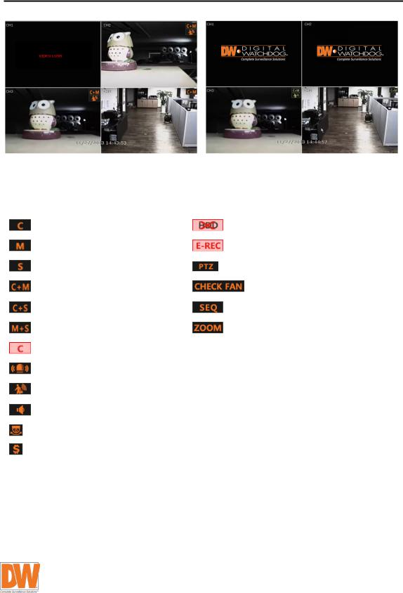
“VIDEO LOSS” is shown on the display screen when no camera is connected or disconnects suddenly. When a camera is disconnected, a warning sound shall be generated depending on the system setting.
Admin users can set different level of authorization for each user, granting them specific access to specific channels. If a certain user is not authorized to view a channel, no image is shown on the display screen as below.
15 | VMAX A1 Plus™ DVR
3.2.2. Icons
In live mode, icons will appear on the screen to notify of the system mode or status.
|
|
Icon shown at the right-upper corner on |
|
|
Icon shown at the right-bottom corner on full |
|
|
||
|
|
|
|
|
|
||||
|
|
each channel screen |
|
|
screen |
|
|
||
|
|
|
Continuous recording |
|
|
No HDD detected |
|
||
|
|
|
|
|
|
|
|
||
|
|
|
Motion detection recording |
|
|
Emergency recording is in use |
|
||
|
|
|
|
|
|
|
|
||
|
|
|
Sensor activated recording |
|
|
PTZ is enabled |
|
||
|
|
|
|
|
|
|
|
||
|
|
|
Continuous + motion alarm |
|
|
Warning for exceeding |
|
||
|
|
|
recording |
|
|
temperature |
|
||
|
|
|
Continuous + sensor activated |
|
|
Sequence mode is enabled |
|
||
|
|
|
Recording |
|
|
|
|||
|
|
|
|
|
|
|
|
||
|
|
|
Motion detection + sensor |
|
|
Digital zoom is enabled |
|
||
|
|
|
activated recording |
|
|
|
|||
|
|
|
|
|
|
|
|
||
|
|
|
Emergency recording |
|
|
|
|
|
|
|
|
|
|
|
|
|
|
|
|
|
|
|
Sensor activated |
|
|
|
|
|
|
|
|
|
|
|
|
|
|
|
|
|
|
|
Motion detected |
|
|
|
|
|
|
|
|
|
|
|
|
|
|
|
|
|
|
|
Audio channel |
|
|
|
|
|
|
|
|
|
|
|
|
|
|
|
|
|
|
|
PTZ camera |
|
|
|
|
|
|
|
|
|
|
|
|
|
|
|
|
|
|
|
Transaction verification |
|
|
|
|
|
|
|
|
|
|
|
|
|
|||
|
|
|
|
|
|||||
|
|
NOTE |
If you cannot find any recording icon in the right corner of screen, the system is not |
|
|||||
|
|
recording. Check the recording schedule or camera in the main setup menu. |
|
||||||
|
|
|
|
|
|
|
|
|
|
User Manual | 16
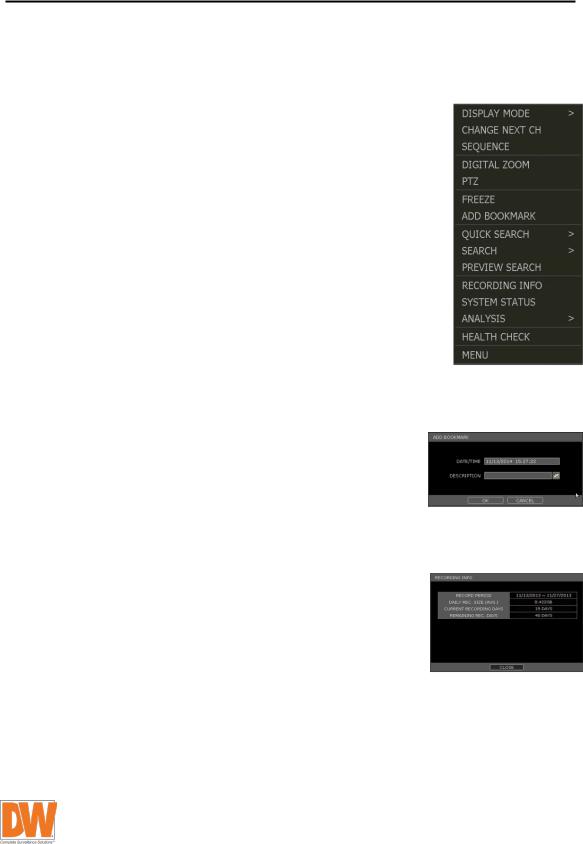
3.2.3. Pop-up Menu
User can click the right button of the mouse to pop up sub-menu as below. If user want to control a specific channel, put the mouse cursor on that channel and then click the right button.
•Display mode: User can change screen display mode from the available split options (1, 4, 6, 9, 10, 13, 16 split option).
•Change next CH: View the next channel or next group of cameras in the current split mode.
•Sequence: When SEQUENCE is selected,  icon will appear on the right-bottom corner of the screen. Display screen will be sequentially changed.
•Digital zoom: Digital zoom is available in single channel view only. When ZOOM is selected,  icon will appear on the right-button corner of the screen and digital zoom control is available.
•To zoom-in, drag the mouse’s cursor on the desired area to create a zoom square. You can also control zoom-in & zoomout by mouse scrolling the mouse’s wheel up and down. Once the image is zoomed-in, user can move the zoom area by clicking on the edge of the square and dragging it.
•To exit from the zoom mode, click the right and select “ZOOM EXIT” in the menu.
•PTZ: Enable PTZ mode. See section 3.3 PTZ Operation for more
information. The available PTZ options depend on the camera’s settings. See the camera’s manual for more information.
•Freeze: Freeze the current live view. System clock (date/time information) will continue running at the bottom of the screen. Select FREEZE again to resume the live view.
•Add to bookmark: Add a bookmark with description on the currently displayed image. When the bookmark menu appears, enter a description and click OK to save.
•Quick search: Select a specific prior time (10sec. / 15sec. / 30sec. / 60sec. / 2min. / 3min. / 5min.) to instantly switch to playback mode.
•Search: Search recorded video using the Calendar, Date/Time, First Data, Last Data, System Log, Event Log, Transaction Verification and Bookmark options. See section 3.5. Search Recorded Image for more information.
•Preview search: Search recorded video in thumbnail search modes. See section 3.5.9 Preview Search for more information.
•Recording info: Check the recording status of the DVR, such as Recording Period, Daily Recording Size (Average), Recording Days and Remaining Recording Days.
•System status: See the system status, including information on the network condition, number of clients currently connected to the DVR etc. A green line means the connection is live and working.
Loading...