


.&("QJY¥ .FHBQJYFM 4VSGBDF .PVOU %PNF $BNFSB
%8$ .7 8J"
User’s Manual 7FS
#FGPSF JOTUBMMJOH BOE VTJOH UIF DBNFSB QMFBTF SFBE UIJT NBOVBM DBSFGVMMZ #F TVSF UP LFFQ JU IBOEZ GPS GVUVSF SFGFSFODF
Safety Information
CAUTION
RISK OF ELECTRIC SHOCK.
DO NOT OPEN.
CAUTION:
TO REDUCE THE RISK OF ELECTRIC SHOCK, DO NOT REMOVE COVER (OR BACK) NO USER SERVICEABLE
PARTS INSIDE. REFER SERVICING TO QUALIFIED SERVICE PERSONNEL.
Warning
This symbol indicates that dangerous voltage consisting a risk of electric shock is present within this unit.
Precaution
This exclamation point symbol is intended to alert the user to the presence of important operating and maintenance (servicing) instructions in the literature accompanying the appliance.
WARNING
To prevent damage which may result in fire or electric shock hazard, do not expose this appliance to rain or moisture.
WARNING
1.Be sure to use only the standard adapter that is specified in the specification sheet. Using any other adapter could cause fire, electrical shock, or damage to the product.
2.Incorrectly connecting the power supply or replacing battery may cause explosion, fire, electric shock, or damage to the product.
3.Do not connect multiple cameras to a single adapter. Exceeding the capacity may cause excessive heat generation or fire.
4.Securely plug the power cord into the power receptacle. Insecure connection may cause fire.
5.When installing the camera, fasten it securely and firmly. A falling camera may cause personal injury.
6.Do not place conductive objects (e.g. screw drivers, coins, metal items, etc.) or containers filled with water on top of the camera. Doing so may cause personal injury due to fire, electric shock, or falling objects.
7.Do not install the unit in humid, dusty, or sooty locations. Doing so may cause fire or electric shock.
8.If any unusual smells or smoke come from the unit, stop using the product. Immediately disconnect the power sorce and contact the service center. Continued use in such a condition may cause fire or electric shock.
9.If this product fails to operate normally, contact the nearest service center. Never disassemble or modify this product in any way.
10.When cleaning, do not spray water directly onto parts of the product. Doing so may cause fire or electric shock.
Precaution
Operating
t Before using, make sure power supply and all other parts are properly connected.
tWhile operating, if any abnormal condition or malfunction is observed, stop using the camera immediately and contact your dealer.
Handling
tDo not disassemble or tamper with parts inside the camera. tDo not drop the camera or subject it to shock or vibration as this can damage the camera.
tClean the clear dome cover with extra care. Scratches and dust can ruin the quality of the camera image.
Installation and Storage
tDo not install the camera in areas of extreme temperature, exceeding the allowed range.
tAvoid installing in humid or dusty environments. tAvoid installing in places where radiation is present.
tAvoid installing in places where there are strong magnetic
tAvoid installing in places where the camera would be subject to strong vibrations.
tNever expose the camera to rain or water.
2

Important Safety Instructions
1.Read these instructions. - All these safety and operating instructions should be read before the product is installed or operated.
2.Keep these instructions. - The safety, operating and use instructions should be retained for future reference.
3.Heed all warnings. - All warnings on the product and in the operating instructions should be adhered to.
4.Follow all instructions. - All operating and use instructions should be followed.
5.Do not use this device near water. - For example: near a bath tub, wash bowl, kitchen sink, laundry tub, in a wet basement; near a swimming pool; etc.
6.Clean only with dry cloth. - Unplug this product from the wall outlet before cleaning. Do not use liquid cleaners.
7.Do not block any ventilation openings. Install in accordance with the manufacturer’s instructions. - Slots and openings in the cabinet are provided for ventilation, to ensure reliable operation of the product, and to protect it from over-heating. The openings should never be blocked by placing the product on bed, sofa, rug or other similar surface. This product should not be placed in a built-in installation such as a bookcase or rack unless proper ventilation is provided and the manufacturer’s unstructions have been adhere to.
8.  that produce heat.
9.Do not defeat the safety purpose of the polarized or grounding-type plug. A polarized plug has two blades with one wider than the other. A grounding type plug has two blades and a third grounding prong. The wide blade
electrician for replacement of the obsolete outlet.
10.Protect the power cord from being walked on or pinched particularly at plugs, convenience receptacles, and the point where they exit from the apparatus.
11. 
12.  manufacturer, or sold with the apparatus. When a cart is used, use caution when moving the cart/apparatus combination to avoid injury from tip-over.
13. Unplug this apparatus during lightning storms or when unused for long periods of time.
14.  in any way, such as power supply cord or plug is damaged, liquid has been spilled or objects have fallen into the apparatus, the apparatus has been exposed to rain or moisture, does not operate normally, or has been dropped.
3

Disposal of Old Appliances
1. When this crossed-out wheel bin symbol is attached to a product it means the product is covered by the European Directive 2002/96/EC.
2. All electrical and electronic products should be disposed of separately form the municipal waste stream stream in accordance to laws designated by the government or the local authorities.
3.The correct disposal of your old appliance will help prevent potential negative consequences for the environment and human health.
waste disposal service or the shop where you purchased the product.
This equipment has been tested and found to comply with the limits for a Class A digital device, pursuant to part 15 of the FCC Rules.
These limits are designed to provide reasonable protection against harmful interference when the equipment is operated in a commercial environment. This equipment generates, uses, and can radiate radio frequency energy and, if not installed and used in accordance with the instruction manual, may cause harmful interference to radio communications. Operation of this equipment in a residential area is likely to cause harmful interference in which case the user will be required to correct the interferenece at his own expense.
4
Introduction -
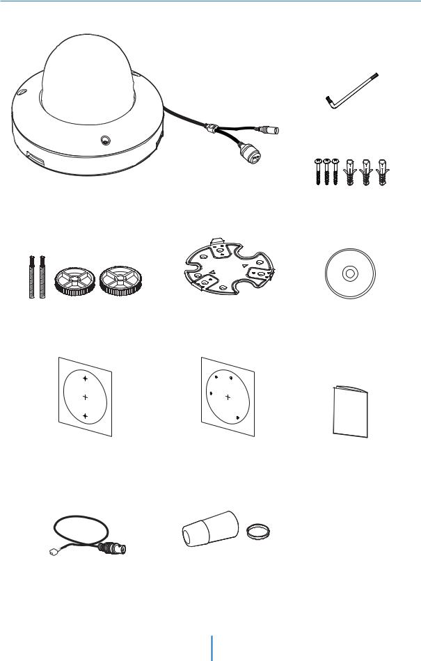
Product & Accessories
Torx Wrench
|
|
Screw & |
Camera |
Cables |
Plastic Anchor-3pcs |
Mount Bolt & Nut |
Mount Plate |
Manual CD |
Template Sheet |
Template Sheet |
|
for Installing by Bolt & Nut |
for Installing by Plate |
Quick Manual |
Test Monitor Cable |
Waterproof cap & Gasket |
5

Introduction -
Part Name
Dome Cover
Test Monitor Cable Connector
Lens
Tilt Stopper Screw
Gimbal
SD Card Slot
Reset Button
Bezel
Bottom Case
RJ-45 Connector
Waterproof cap
DC Power Jack
Mount Plate
Plate Hook
6
Installation -
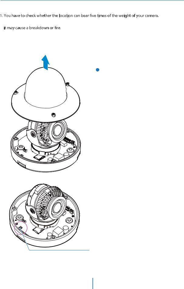
Disassemble the camera
Before installing your camera, you have to read the following cautions.
2.Don’t let the cable to be caught in improper place or the electric line cover to be damaged. Otherwise
3.When installing your camera, don’t allow any person to approach the installation site. If you have any valuable things under the place, move them away.
1 Detach the dome cover by torx wrench provided from bottom case before installation the camera.
 Reset to the Factory Default
Press the reset button for 5 seconds to return the setup to the factory default.
 Warning:
If you press the ‘Reset’ button, you will lose all setting data. If needed, please, make a note for further installation.
Reset Button
7
Installation -
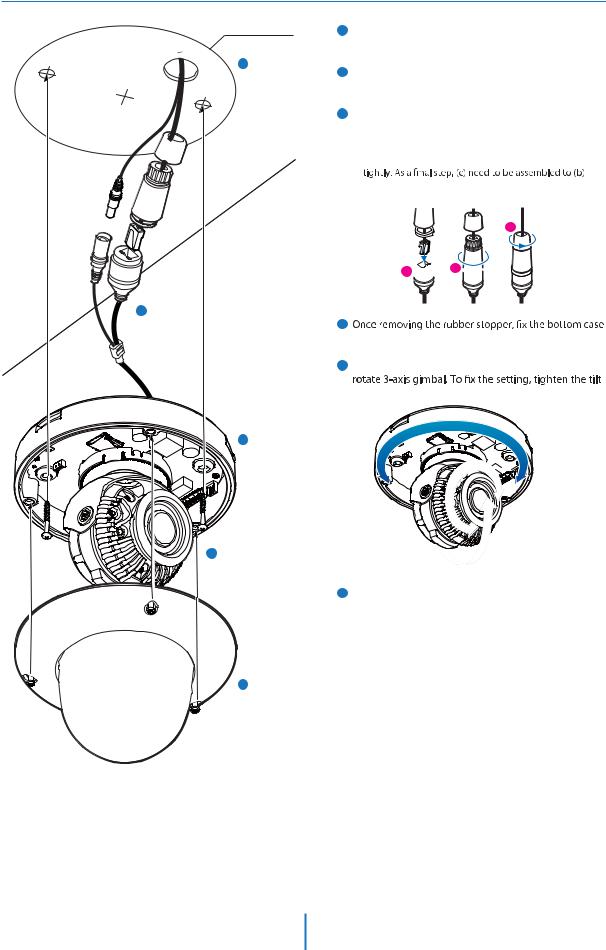
Installation
Template Sheet
2
3
4
5
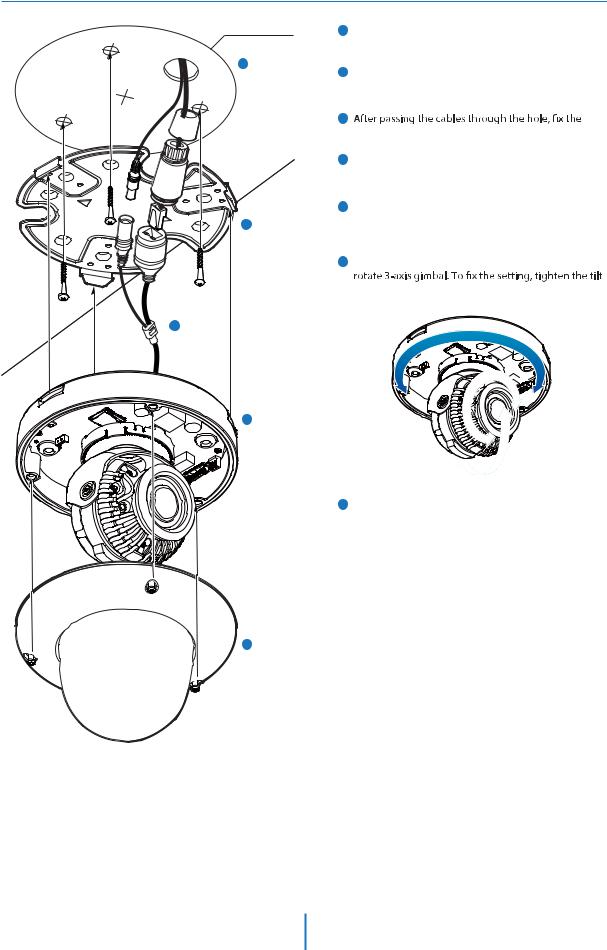
1Disassemble the camera. See the section ‘Installation - Disassemble the camera’ for details.
2Using the template sheet, make the cabling hole on the wall/ceiling.
3Connect the network cable and power cable respectively. See the section 'Installation - Cabling' for details.
 Put the Lan cable into (a), then (b) will be assembled to (a)
without making any space.
c
a b
b
4
on the ceiling.
5To achieve desired view direction and orientation, stopper screw.
6 Attach the dome cover to the bottom case.
 Warning:
DO NOT TOUCH THE SURFACE OF THE BUBBLE.
CleanView™ Hydrophobic Dome Coating Repels.
6
8
Installation -
Installation Using Mount Plate
Template Sheet
2
3
4
5
1Disassemble the camera. See the section ‘Installation - Disassemble the camera’ for details.
2Using the template sheet, make the cabling hole on the wall/ceiling.
3
mount plate on the template sheet.
4Connect the network cable and power cable respectively.
See the section 'Installation - Cabling' for details.
5Fix the bottom case on the mount plate. Press 3 bezels on bottom case of camera till it sounds snap to lock the camera to the mount plate.
6To achieve desired view direction and orientation, stopper screw.
7 Attach the dome cover to the bottom case.
 Warning:
DO NOT TOUCH THE SURFACE OF THE BUBBLE.
CleanView™ Hydrophobic Dome Coating Repels.
7
9
Installation -
Installation Using Mount Bolt & Nut
Template Sheet |
1 |
Disassemble the camera. See the section ‘Installation - |
|
Disassemble the camera’ for details.
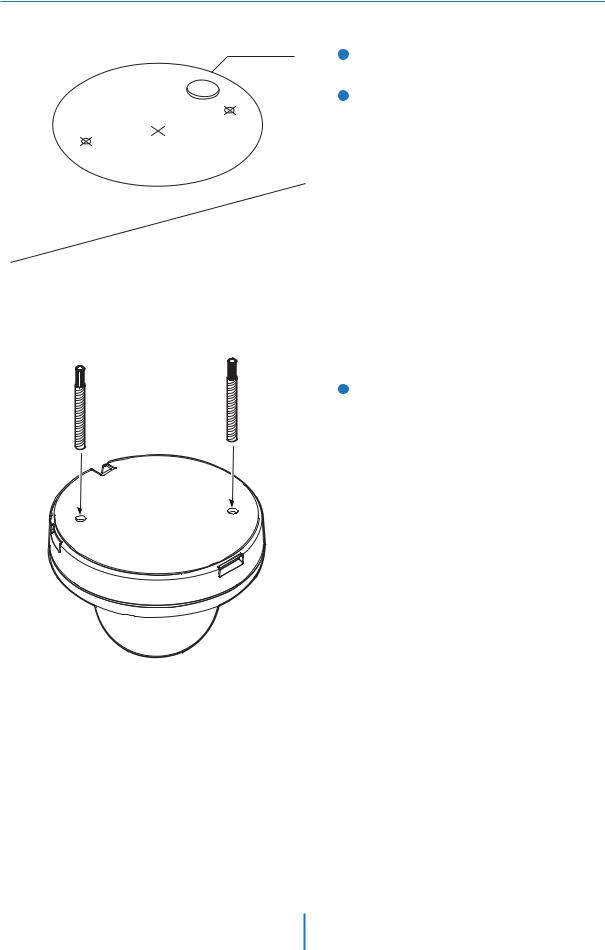
2 Using the template sheet, make the cabling holes on the ceiling panel.
3 Insert the 2 mount bolts into bottom case of camera.
10
Installation -
Installation Using Mount Bolt & Nut
4 Insert the mount bolts into template holes after connecting the cable.
5 Fix the bottom case by tightening mount nuts to mount bolts on the ceiling panel.
6 To achieve desired view direction and orientation,
stopper screw.
7 Attach the dome cover to the bottom case.
 Warning:
DO NOT TOUCH THE SURFACE OF THE BUBBLE.
CleanView™ Hydrophobic Dome Coating Repels.
11
Installation -
Cabling
Two Options
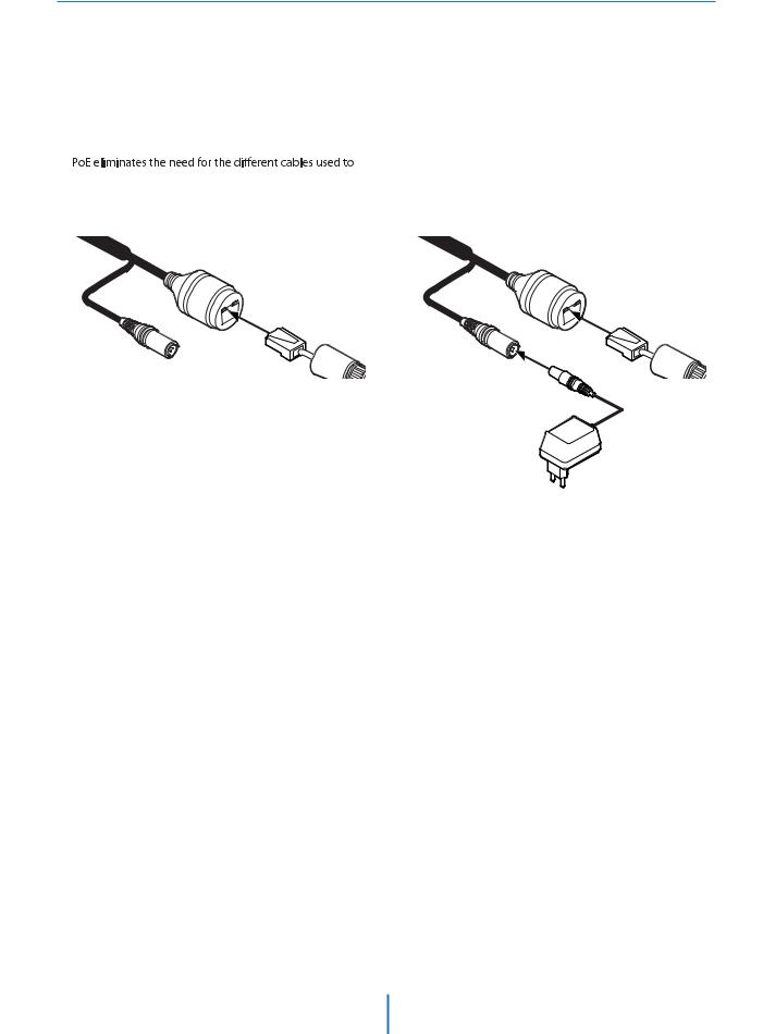
Use a PoE-enabled switch to connect data and power through a single cable and begin viewing and recording images instantly. A non-PoE switch will require an adaptor for power transmission.
1. Using a PoE-Enabled Switch |
2. Using a Non-PoE Switch |
The Camera is PoE-compliant, allowing transmission of |
If a PoE-enabled switch is not used, use a power adaptor |
power and data via a single Ethernet cable. |
for power transmission and non-PoE switch for data |
|
transmission. |
power, record, or control the camera. Follow the illustration |
Follow the illustrations below to connect the camera |
below to connect the camera to a PoE-enabled switch using |
without a PoE-enabled Switch. |
an Ethernet cable. |
|
Ethernet cable |
Ethernet cable |
Power
12
Installation -
Inserting/Removing an SD Memory Card
The memory card is an external data storage device that has  to record and share video, audio, and text data using digital devices.
Micro
 Recommended SD Card Specification (Not Included)
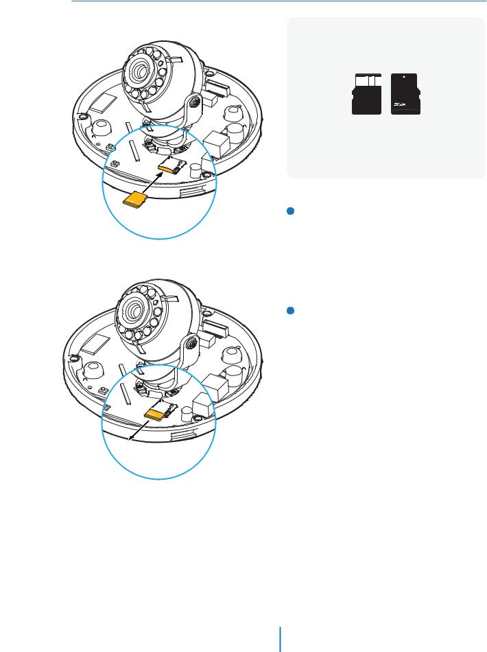
- Type: Micro SD (SD/SDHC/SDXC)
- Manufacturer: Transcend, Kingston, Toshiba, SanDisk - Capacity: 4GB ~ 128GB
- Class: over UHS-I U3 Class 10
1 Inserting an SD Memory Card
Insert the SD card in the arrow direction.
 Don’t insert the SD memory card while it’s upside down by force.
Otherwise, it may damage the SD memory card.
2 Removing an SD Memory Card
Removing an SD Memory Card Gently press down on the exposed end of the memory card as shown in the diagram to eject the memory card from the slot.
 Pressing too hard on the SD memory card can cause the card to shoot out uncontrollably from the slot when released.
 If you have saved data in the SD memory card, removing the SD memory card prior to setting record to OFF will cause damage to the data stored in the card.
13
/FUXPSL 4FUVQ
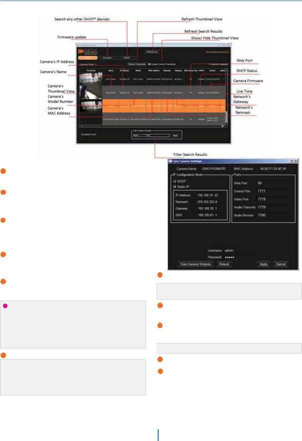
%8 *1 'JOEFS
(P UP IUUQ XXX EJHJUBM XBUDIEPH DPN BOE TFBSDI GPS A*1 'JOEFS PO UIF RVJDL TFBSDI CBS BU UIF UPQ PG UIF QBHF
5IF MBUFTU *1 'JOEFS TPGUXBSF XJMM BQQFBS JO UIF TFBSDI SFTVMUT $MJDL PO UIF MJOL UP EPXOMPBE UIF GJMF UP ZPVS DPNQVUFS
5IF TPGUXBSF XJMM TDBO ZPVS OFUXPSL GPS BMM TVQQPSUFE DBNFSBT BOE EJTQMBZ UIF SFTVMUT JO UIF UBCMF "MMPX VQ UP TFDPOET GPS UIF *1 *OTUBMMFS UP GJOE UIF DBNFSB PO UIF OFUXPSL
ZPV DBO QSFTT UIF h3FGSFTI -JTUh UP TFBSDI UIF OFUXPSL BHBJO PS GJMUFS UIF TFBSDI SFTVMUT CZ FOUFSJOH B WBMVF JO UIF GJMUFS CPY BU UIF CPUUPN PG UIF QBHF
$IFDL UIF CPY OFYU UP h%JTQMBZ $BNFSB 5IVNCOBJMh UP WJFX B +1&( JNBHF PG UIF DBNFSBhT WJFX OFYU UP UIF DBNFSB OBNF PO TVQQPSUFE NPEFMT
 4FMFDU %)$1 JG UIF JOUFSOFU TFSWJDF JT EZOBNJD *1 5IJT XJMM BMMPX UIF
4FMFDU B DBNFSB GSPN UIF MJTU CZ EPVCMF DMJDLJOH PO JU 5IF
DBNFSB UP SFDFJWF JUT *1 BEESFTT GSPN UIF %)$1 TFSWFS
DBNFSBhT OFUXPSL JOGPSNBUJPO XJMM BQQFBS *G OFDFTTBSZ ZPV
 DBO4FMFDUBEKVTU45"5*UIF$ UPDBNFSBNBOVBMMZT OFUXPSLFOUFS UIF DBNFSBUZQF T *1 BEESFTT TVCOFU
NBTL (BUFXBZ BOE %/4 JOGPSNBUJPO
 $POUBDU ZPVS OFUXPSL BENJOJTUSBUPS GPS NPSF JOGPSNBUJPO
5IF DBNFSBhT EFGBVMU OFUXPSL JOGPSNBUJPO JT
 %FGBVMU5$1 *1 JOGPSNBUJPO*14VCOFU .BTL(BUFXBZ%/4
5P WJFX UIF DBNFSBhT XFC DMJFOU DMJDL PO h7JFX $BNFSB 8FCTJUFh
 "A1PSU 'PSXBSEJOH IBT UP CF TFU JO ZPVS OFUXPSLT SPVUFS GPS FYUFSOBM BDDFTT UP UIF DBNFSB
5P TBWF UIF DIBOHFT NBEF UP UIF DBNFSBhT TFUUJOHT JOQVU *% BOE 18 PG UIF DBNFSB GPS BVUIFOUJDBUJPO
*G UIF DBNFSB OFFET UP CF SFCPPUFE BGUFS UIF TFUUJOHT XFSF DIBOHFE QSFTT UIF h3FCPPUh CVUUPO 5IF DBNFSB XJMM QPXFS DZDMF BOE XJMM BQQFBS CBDL JO UIF TFBSDI SFTVMUT PODF UIF SFCPPU JT DPNQMFUF

 %FGBVMU *% 18 BENJO BENJO
$MJDLA4BWF UP TBWF DIBOHFE WBMVFT
5P VQEBUF UIF DBNFSBhT GJSNXBSF GSPN UIF %8 *1 'JOEFS DMJDL PO UIF GJSNXBSF UBC VQMPBE UIF GJSNXBSF GJMF BOE TFMFDU UIF DBNFSBT UP VQEBUF :PV DBO VQEBUF NVMUJQMF DBNFSBT BU UIF TBNF UJNF
Network Setup -
Quick Start of Network Connection
Please follow the steps below to complete the initial setup of the network function.
 Please do not power on the IP Camera until instructed.
Explorer.
 If connecting the IP Camera directly to a modem, power down and reset the modem. Leave the modem powered down until con
 tions ar
 nalized with the IP Camera and the IP Camera has been correctly connected to the modem.
1. 2. Open the IP Installer on a PC, then search for the IP camera.
 If you have a DHCP server, it will automatically set the Camera IP.
 If you do not have a DHCP server, Camera IP is set to 192.168.1.80 after one minute. In this case, PC IP must be changed to the IP to be able to access the 192.168.1.80.
3.If multiple numbers of camera are connected it should be distinguished by the mac address of the Camera.
4.Click the Camera IP, and connect to the WEB PAGE.
5.Default ID/Password to access IP Camera are both the word: admin.
6.Familiarize yourself with the Viewer Interface Screen.
7.please install VLC to display live video.
8.The IP setting can be set to ‘STATIC’ at IP Installer or web viewer followed by Setup -> Network -> Network Settings.
9.If the IP Camera is connected to a network which utilizes a
router, you must have Port Forwarding co ured on your personal router to forward all ports to the IP address you have assigned the IP Camera.
10. 
(if necessary), you may access your IP Camera on your local network by opening Internet Explorer and specifying the IP address and Web Port that you have assigned to the IP Camera.
 Example: http://192.168.0.200:8888
 If you leave your Web Port set to 80, you don’t need to specify the port in the Address Bar to access to your IP Camera.
11.Access your IP Camera via the Internet :
If you use a static IP address assigned by your ISP
1)Open Internet Explorer.
2)Type the IP of the IP Camera.
3)If you use a router, type the routers’ static IP and the web port number of the IP Camera.
If you have a dynamic address provided by your ISP
1)Open Internet Explorer and visit the DDNS website.
2)Register the IP Camera.
3)Reboot the IP Camera.
4)Give the DDNS server 10 minutes to locate your IP Camera’s IP information.
5)Click the refresh button in the Internet Explore.
6)After your camera is connected, select your camera.
15

Network Setup -
DDNS Registration
If you have DYNAMIC IP service from your Internet Service Provider (ISP), you can’t tell the current IP address of the IP Camera.
To solve this problem, you have to register to our DDNS service.
A t, you have to check if you are using dynamic addressing. If so, register your IP Video Server on our DDNS website before you c
 re, setup, or install the IP Camera.
Even though your IP is not dynamic, you will
just remember ‘hostname.dyndns.com/gate1’ instead of complicated series of numbers like http://201.23.4.76:8078.
For more details, contact our Support Center.
 To use a public DDNS called ‘dyndns’ or ‘no-ip’, refer to the detail information on how to use the service.
(Visit the web site : http://www.dyndns.com or http://www.no-ip.com)
16
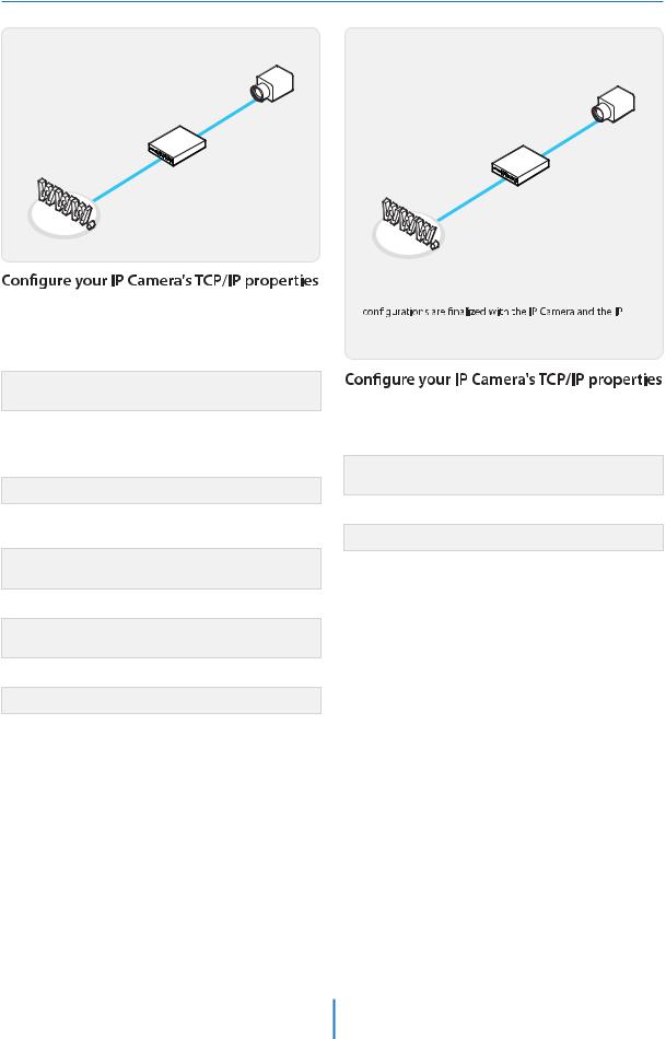
Network Setup -
Guide to Network Environment
Please configure the IP Camera at the installation site. You must determine your network scenario in order to configure the IP Camera with the proper TCP/IP settings. This tutorial will guide you through the process. Before actually configuring the IP Camera, determine settings to be applied.
Record those settings to be used to configure your IP Camera for reference.
When configuring your IP Camera, treat the IP Camera as another PC on your network. You will assign it several addresses and other TCP/IP properties to match your current network.
This step-by-step tutorial will teach what IP addresses and network configurations should be assigned based on the network scenario.
5.The following descriptions are several basic network scenarios. Determine which scenario describes your network. If your network does not match one of the scenarios below and you are unsure how to setup your IP Camera, contact your network administrator and then call our Support Center.
 You cannot control the rectangular gray areas and only the ISP has access to the devices.
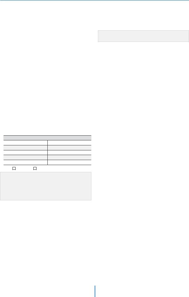
1.Before you begin, locate any information and settings received from your Internet Service Provider (ISP). You may need to refer to these IP addresses at a later time during the configuration.
Current TCP/IP Settings
IP Address
Subnet Mask
Default Gateway
Primary DNS Server
Secondary DNS Server (Option)
Static Dynamic
 If you were not given any IP addresses or the ISP was responsible for the setup and installation of your Internet connection, go to step 2.
 If you are not using a router on your network, your ‘Current TCP/IP Settings’ (from the previous section) and ‘Assigned IP Addresses from My ISP’ will be exactly the same.
2.You must determine whether the IP address is STATIC or DYNAMIC. At this moment, you are only concerned about the ISP. Did they provide you with a STATIC or DYNAMIC address? If you are unsure, contact your ISP.
3.Configure your IP Camera’s TCP/IP settings for network connectivity by selecting Setup from the main interface and selecting TCP/IP located on the left of the Setup screen.
4.If prompted for ID and Password, use ‘admin’ for both entries.
The default web port number is 80. If port 80 is blocked by the ISP, a value between 1025 ~ 60000 should be used. If TCP port 80 is blocked, consult the ISP
17
Network Setup -
Setup Case A, B
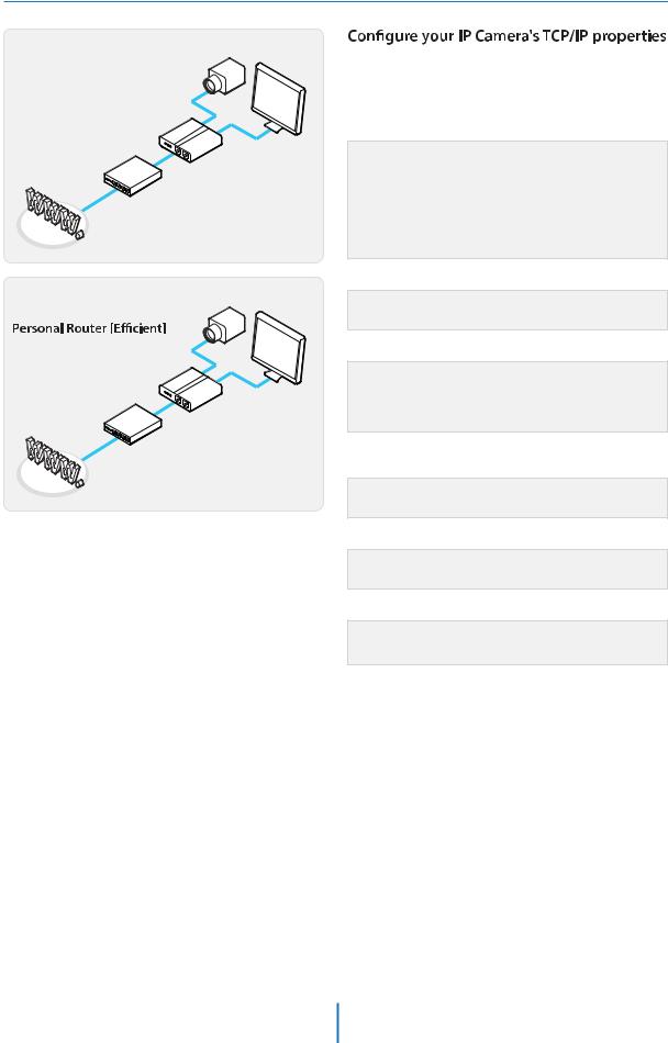
Case A:
Dynamic IP +
Personal Router [Most SOHO]
Camera
PC
Personal Router
W/Intergrated Switch
Phone Line |
Cable/xDSL Modem |
or CATV |
|
|
(ISP Provided) |
Internet |
|
Case B:
Static(Fixed) IP +
Camera
PC
Personal Router
W/Intergrated Switch
Public Line |
Gateway or Router |
|
at ISP |
Internet
as follows :
1. Network Type : STATIC (even though you have Dynamic IP from your ISP, use STATIC on the IP Camera)
2. Internet Address : A private IP address such as 192.168.0.200 (Example)
 You need to assign an IP address to the IP Camera just as you do with PC.
 The IP address you assign must be unique to your network and match your network as well. For information on how to choose a unique IP and match your network, read the FAQ.
 The IP address you assign must be a private IP. For information on how to choose a private IP please, read the FAQ.
3. Subnet Mask : 255.255.255.0 (Example)
 You must use the same subnet mask as the one you noted under ‘Current TCP/IP Settings’.
4. Default Gateway : 192.168.0.1 (Example)
 This IP address must be the IP address of your router. (private or LAN side)
 Use the same Default Gateway you noted under ‘Current TCP/IP Settings’.
5. Preferred DNS Server : Use the 1st DNS Server from ‘Assigned IP Address from My ISP’.
 If you did not receive any IP addresses from your ISP, contact the ISP and acquire the IP address of their DNS server.
6. DDNS Server : Use the DDNS server.
 This is the same site you will register later to accommodate dynamic IP from your ISP.
7. Web Port : 8888
 Do not use the default port 80 as this number must be changed.
  You may select any number between 1025 ~ 60000.
18
Network Setup -
Setup Case C, D
Case C:
Static(Fixed) IP [Dedicated line directly to the IP Camera]
Case D:
Dynamic IP + DSL/Cable Modem [Connected
directly to the IP Camera]
Camera
Camera
Phone Line
or CATV Cable/xDSL Modem
(ISP Provided)
Public Line
Gateway or
Router at ISP
Internet
Internet
as follows :
1.Network Type : STATIC
2.Internet Address : A static IP address received from your ISP such
as 24.107.88.125 (Example)
 You need to assign an IP address to the IP Camera just as you do with PC.
3. Subnet Mask : Subnet mask assigned from your ISP such as 255.255.255.240 (Example)
4. Default Gateway : 24.107.88.113 (Example)
 Use the assigned default gateway from your ISP
5. Preferred DNS Server : Use the 1st DNS Server from ‘Assigned IP Address from My ISP’
 If you have not received any IP addresses from your ISP, contact them to acquire the IP address of their DNS server.
6. DDNS Server : Use the DDNS server
 This is the same site you will register later to utilize our DDNS service.
7. Web Port : 80
 You may select any number between 1025 ~ 60000.
 To connect the IP Camera directly to a modem, power down and reset the modem. Leave the modem powered down until
Camera has been connected correctly to the modem. Then power on the modem, followed by the IP Camera.
as follows :
1.Network Type : DYNAMIC
2.DDNS Server : Use the DDNS server
 This is the same site you will register later to accommodate dynamic IP from your ISP.
3. Web Port : 80
 You may select any number between 1025 ~ 60000.
19
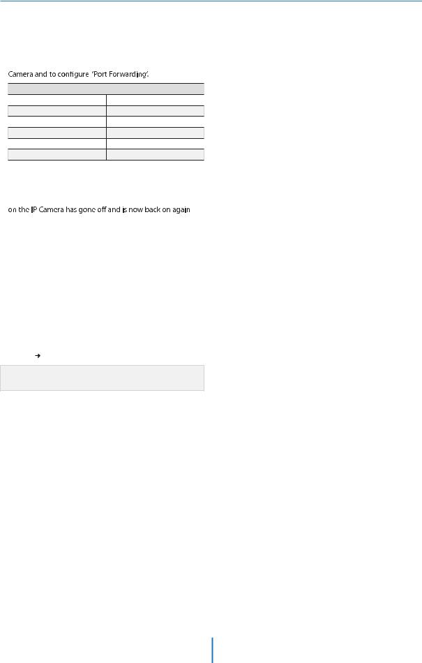
Network Setup -
Port Forwarding
After entering the correct TCP/IP settings, you are ready for ‘Port Forwarding’(Cases A, B).
1.Please record the TCP/IP settings of your IP Camera for future reference. You may need this information to access your IP
IP Camera TCP/IP Settings
IP Address
Subnet Mask
Default Gateway
Preferred DNS Server
DDNS Server
Web Port
2.After clicking ‘Apply’, the system will prompt for a reboot. Please allow the system 50 seconds to reboot and accept the
changes. After 50 seconds, close the con ration screen. The view will display ‘Trying to Reconnect’. If the ACTIVE light
 , the IP Camera has rebooted. After the system reboots completely, remove the power supply from the unit and close Internet Explorer.
3.Return your PC/Laptop TCP/IP properties to their original settings.
4.Before installing the IP Camera, you must use ‘Port Forwarding’ on your personal router (Cases A, B).
You will need to forward 1 ports:
tWeb Port
All the ports will be forwarded to the IP address you assigned to the IP Camera.
In the example above, you would forward:
t
 For information on how to use ‘Port Forwarding’, please read Appendix C.
20
Network Setup -
Starting IP Camera
After forwarding correctly the Web Port, through your router (if applicable), install the IP Camera in a proper location.
1.Locate the serial number located on the label attached to the bottom of the IP Camera, you will need this for DDNS registration.
2.Connect the IP Camera to your router or cable/DSL modem (per your network scenario) via a Cat5/5e UTP Ethernet network cable.
3.Supply power to the IP Camera.
4.After 1 minute, verify the IP Camera indicators: t-*/,Flickering/Solid
5. 
(if necessary), access your IP Camera on your local network by opening Internet Explorer and specifying the IP address and Web Port assigned to the IP Camera.
 Examples: http://192.168.0.200:8888 or http://24.106.88.123
 If you left your Web Port set to 80, do not need to specify the port in the Address Bar to access the IP Camera.
6. Access your IP Camera via the Internet :
If you use Case B, C
1)Open Internet Explorer.
2)Type the IP of the IP Camera.
If you use Case A, D
1)Open Internet Explorer.
2)Visit the DDNS website.
3)Register the IP Camera.
4)Give the DDNS server 10 minutes (MAX) to locate your IP Camera’s IP information. You may reboot the server to send an immediate request to our DDNS server.
5)After your camera is connected, select your camera.
 The di
 ence between B and C is that B needs to set the port forwarding.
 Since the type of DDNS
  s from the service type, refer to the related service site.
21
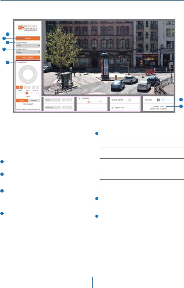
Web Viewer Screen -
Basic Screen
1
2
3
4
5
 Web viewer is optimized with explorer10 or above version and Firefox.
 If VLC is not installed or VLC plugin is not supported (Chrome), Live buffering and Channel select menu on 3, 4 will be changed to Live Viewer menu, and then if HTML5(MJPEG) is selected on Live Viewer menu, then you can check the video.
1Live video display. This is the region for live video stream from the camera.
2Setup popup button. Click it to open the Setup page to setup details of IP camera like Video, Network, Events, System and etc. See the section ‘Setup’ .
3When the image goes unsmoothly because of bad network connection, it stored image during setup time and shows the image on the live view screen.
 User will see the delayed images as much as setup time.
4Channel Select button. Select a stream produced from the camera between Stream 1 ~ 3 to display it in the live view screen.
6
7
5Below “Menu”is supported in accordance with models.
PTZ Control
This camera model supports the zoom and focus.
Preset
Does not support.
Speaker Control
Does not support.
Alarm Input
Does not support.
Relay Out
Does not support.
6Motion
It shows the Motion event status.
 Event Alert Icon (
  ) appears if ‘Motion Detection’ is activated.
7Camera Time
Display the camera time.
 Refer the ‘Setup > Video & Audio > Video’ to setup the Video Stream.
22
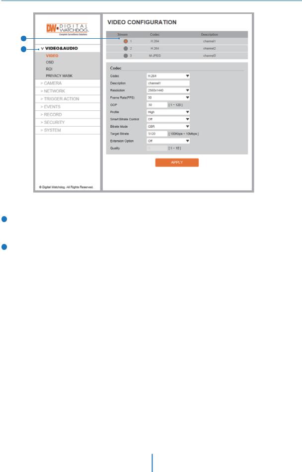
Setup -
Video Configuration
1
2
1Detail Page
When you selects an item from the menu, you can set the details for the selected item.
2Setup Constitution Video&Audio
[ VIDEO, OSD, ROI, PRIVACY MASK ]
Camera
[ IMAGE ADJUSTMENT, EXPOSURE, DAY&NIGHT, BACKLIGHT, WHITE BALANCE, IMAGE, VIDEO ]
Network
[ STATUS, NETWORK SETTING, AUTO IP, ONVIF, UPNP, DDNS, FTP, SMTP, SNMP, RTSP INFORMATION ]
Trigger Action
[ ACTION RULES, IMAGE TRANSFER ]
Events
[ EVENT RULES, MOTION, TEMPERATURE ]
Record
[ MANAGEMENT, RECORD LIST, STORAGE ]
Security
[ IP ADDRESS FILTER, RTSP AUTHENTICATION, IEEE 802.1x, HTTPS, CERTIFICATES, SERVICE ]
System
[ INFORMATION, FIRMWARE UPDATE, DATE&TIME, DST, USER MANAGEMENT, LOG, FACTORY RESET, RESTART ]
23
Setup -
Video Configuration
1
2
3
4
5
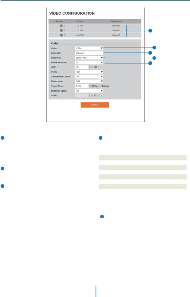
1Live Video Channel Setup
The video can be configured to variety settings with a combination of codec and resolution.
The camera performance has to be considered when setting multiple channels. This effects on the performance of the camera.
2Codec
Choose the video codec. According to the selected codec, the subcategories can be changed automatically.
3Description
Input the additional description about the selected channel. Max. 30 alphabets are allowed(Including space). For the description, English Alphabets, numbers and special characters ( - _ @ . ) can be used.
4Resolution
Select the video resolution.
 Available resolution can be depends on the codec setup between the channels.
|
NTSC |
PAL |
|
4M |
2560 x 1440 |
2560 x 1440 |
|
|
|
|
|
3M |
2304 x 1296 |
2304 x 1296 |
|
|
|
|
|
1080p/i |
1920 x 1080 |
1920 x 1080 |
|
|
|
|
|
720p/i |
1280 x 720 |
1280 x 720 |
|
|
|
|
|
SVGA |
800 x 600 |
800 x 600 |
|
|
|
|
|
VGA |
640 x 480 |
640 x 480 |
|
|
|
|
|
4CIF |
704 x 576 |
704 x 576 |
|
704 x 480 |
704 x 480 |
||
|
|||
|
|
|
|
CIF |
352 x 288 |
352 x 288 |
|
352 x 240 |
352 x 240 |
||
|
|||
|
|
|
<Resolution of Video Format>
5Frame Rate
Select the maximum Frame Rate.
 Available Frame Rate can be different although same codecs were set up.
24
Setup -
Video Configuration
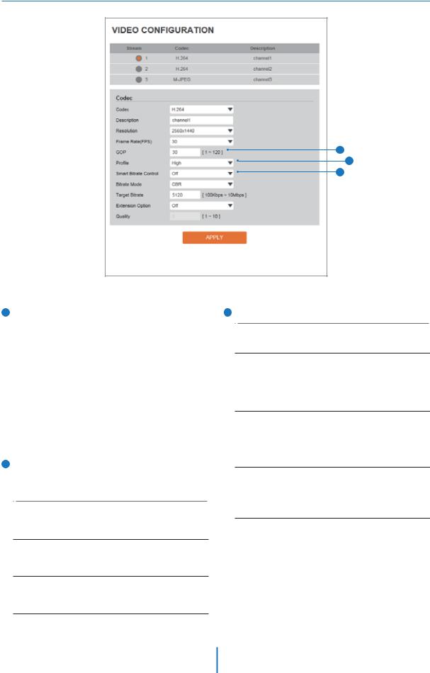
6GOP(Group of Pictures) Size
Set up the number of frames (P-frame) which contain only changed information based on basic frame (I-frame). Regarding videos with lots of movement, if you set GOP size bigger, only the number of P-frames is bigger. As a result, video resolution will be low but ‘File size’ and ‘Bit-rate can be decreased.
 GOP(Group of Pictures) Size is..
I-frame and P-frame can be created for MPEG4 and H.264 video compression. I-frame(=key-frame) means the whole image data for one specific scene of video. P-frame is image data which has been changed information compared to I-frame GOP is made up of one I-frame and corresponding several P-frames. To improve video quality, set the number of P-frames smaller and to decrease image size, set the number of P-frames bigger.
7Profile
The profile defines the subset of bit stream features in an H.264 stream, including color reproduction and additional video compression.
Baseline
A simple profile with a low compression ratio.
The Baseline profile supports I-frames and P-frames.
Main
An intermediate profile with a medium compression ratio. The main profile supports I-frames, P-frames, and B-frames.
High
A complex profile with a high compression ratio.
The high profile supports I-frames, P-frames, and B-frames.
6
7
8
8Smart Bitrate Control
Off
You can not use the Smart Bitrate Control function.
CVBR (Framerate priority)
This Mode is for cameras which do not want absolute any frame drop, but still want to get lower bitrate. It has limitation when the Target bitrate is set to be very low, but actual motion is big or scene is very noisy.
CVBR (Quality priority)
When the Target bitrate is set to very low, and motion is big, then LBR will try to drop frames, and make the final fps to be lower, so that it can save its and make the output frames to have better quality.
CBR
This Mode is a CBR alike mode which is close to traditional security IPCAM, and it's not designed for LBR, It's provided as an option in LBR library just to help comparison.
25
 Loading...