


MEGApix® PanoTM 9MP Vandal
Dome Fisheye IP Camera
DWC-PVF9Di2TW
User’s Manual Ver. 06/20
Before installing and using the camera, please read this manual carefully. Be sure to keep it handy for future reference.

 Safety Information


CAUTION
RISK OF ELECTRIC SHOCK.
DO NOT OPEN.
CAUTION :
TO REDUCE THE RISK OF ELECTRIC SHOCK, DO NOT REMOVE COVER (OR BACK) NO USER SERVICEABLE
PARTS INSIDE.
REFER SERVICING TO QUALIFIED SERVICE PERSONNEL.
Warning
This symbol indicates that dangerous voltage consisting of a risk of electric shock is present within this unit.
WARNING
To prevent damage which may result in fire or electric shock hazard, do not expose this appliance to rain or moisture.
WARNING
1.Be sure to use only the standard adapter that is specified in the specification sheet. Using any other adapter could cause fire, electrical shock, or damage to
the product.
2.Incorrectly connecting the power supply or replacing the battery may cause an explosion, fire, electric shock, or damage to the product.
3.Do not connect multiple cameras to a single adapter. Exceeding the capacity may cause excessive heat generation or fire.
4.Securely plug the power cord into the power receptacle. An insecure connection may cause fire.
5.When installing the camera, fasten it securely and firmly. A falling camera may cause personal injury.
6.Do not place conductive objects (e.g. screwdrivers, coins, metal items, etc.) or containers filled with water on top of the camera. Doing so may cause personal injury due to fire, electric shock, or falling objects.
7.Do not install the unit in humid, dusty, or sooty locations. Doing so may cause fire or electric shock.
8.If any unusual smells or smoke come from the unit, stop using the product. Immediately disconnect the power source and contact the service center. Continued use in such a condition may cause fire or electric shock.
9.If this product fails to operate normally, contact the nearest service center. Never disassemble or modify this product in any way.
10.When cleaning, do not spray water directly onto parts of the product. Doing so may cause fire or electric shock.
Precaution
This exclamation point symbol is intended to alert the user to the presence of important operating and maintenance (servicing) instructions in the literature accompanying the appliance.
Precaution
Operating
•Before using, make sure the power supply and all other parts are properly connected.
•While operating, if any abnormal condition or malfunction is observed, stop using the camera immediately and contact your dealer.
Handling
•Do not disassemble or tamper with parts inside the camera.
•Do not drop the camera or subject it to shock or vibration as this can damage the camera.
•Clean the clear dome cover with extra care. Scratches and dust can ruin the quality of the camera image.
Installation and Storage
•Do not install the camera in areas of extreme temperature, exceeding the allowed range.
•Avoid installing in humid or dusty environments.
•Avoid installing in places where radiation is present.
•Avoid installing in places where there are strong magnetic fields and electric signals.
•Avoid installing in places where the camera would be subject to strong vibrations.
•Never expose the camera to rain or water.
2
 Important Safety Instructions


1.Read these Instructions. - All these safety and operating instructions should be read before the product is installed or operated.
2.Keep these Instructions. - The safety, operating and use instructions should be retained for future reference.
3.Heed all warnings. - All warnings on the product and in the operating instructions should be adhered to.
4.Follow all instructions. - All operating and use instructions should be followed.
5.Do not use this device near water. - For example: near a bathtub, washbowl, kitchen sink, laundry tub, in a wet basement; near a swimming pool; etc.
6.Clean only with a dry cloth. - Unplug this product from the wall outlet before cleaning. Do not use liquid cleaners.
7.Do not block any ventilation openings. Install following the manufacturer’s instructions. - Slots and openings in the cabinet are provided for ventilation, to ensure reliable operation of the product, and to protect it from over-
heating. The openings should never be blocked by placing the product on a bed, sofa, rug, or other similar surfaces. This product should not be placed in a built-in installation such as a bookcase or rack unless proper ventilation is provided and the manufacturer’s instructions have been adhered to.
8.Do not install near any heat sources such as radiators, heat registers, or other apparatus (including amplifiers) that produce heat.
9.Do not defeat the safety purpose of the polarized or grounding-type plug. A polarized plug has two blades with one wider than the other. A grounding type plug has two blades and a third grounding prong. The wide blade or the third prong are provided for your safety. If the provided plug does not fit into your outlet, consult an electrician for replacement of the obsolete outlet.
10.Protect the power cord from being walked on or pinched particularly at plugs, convenience receptacles, and the point where they exit from the apparatus.
11.Only use attachments/accessories specified by the manufacturer.
12.Use only with cart, stand, tripod, bracket, or table specified by the manufacturer, or sold
with the apparatus. When a cart is used, use caution when moving the cart/apparatus combination to avoid injury from tip-over.
13. Unplug this apparatus during lightning storms or when unused for long periods.
14. Refer all servicing to qualified service personnel. Servicing is required when the apparatus has  in any way, such as power supply cord or plug is damaged, liquid has been spilled or objects have fallen into the
apparatus, the apparatus has been exposed to rain or moisture, does not operate normally, or has been dropped.
Disposal of Old Appliances
1. When this crossed-out wheel bin symbol is attached to a product it means the product is covered by the European Directive 2002/96/EC.
2.All electrical and electronic products should be disposed of separately from the
municipal waste stream per laws designated by the government or the local authorities.
3.The correct disposal of your old appliance will help prevent potential negative
consequences for the environment and human health.
4.For more detailed information about disposal of your old appliance, please contact your city office, waste disposal service or the shop where you purchased the product.
This equipment has been tested and found to comply with the limits for a Class A digital device, pursuant to part 15 of the FCC Rules. These limits are designed to provide reasonable protection against harmful interference when the equipment is operated in a commercial environment.
This equipment generates, uses, and can radiate radio frequency energy and, if not installed and used in accordance with the instruction manual, may cause harmful interference to radio communications. Operation of this equipment in a residential area is likely to cause harmful interference in which case the user will be required to correct the interference at his own expense.
3

Table of Contents
Introduction |
|
Product and accessories.................................................................................................................................................................. |
5 |
Parts identification............................................................................................................................................................................ |
6 |
Installation |
|
Disassembling the camera............................................................................................................................................................. |
7 |
Factory reset........................................................................................................................................................................................ |
7 |
Installation............................................................................................................................................................................................ |
8 |
Cabling................................................................................................................................................................................................ |
11 |
Managing the SD Card.................................................................................................................................................................. |
13 |
Network Setup |
|
DW IP finder....................................................................................................................................................................................... |
14 |
Web Viewer |
|
Login to the camera....................................................................................................................................................................... |
15 |
GUI overview..................................................................................................................................................................................... |
16 |
Camera Settings |
|
Settings > Video and audio setup............................................................................................................................................. |
17 |
Settings > Camera setup > Image adjustment..................................................................................................................... |
25 |
Settings > Camera setup > Exposure settings...................................................................................................................... |
26 |
Settings > Camera setup > Day and night settings............................................................................................................ |
27 |
Settings > Camera setup > Backlight settings...................................................................................................................... |
28 |
Settings > Camera setup > White Balance settings............................................................................................................ |
29 |
Settings > Camera setup > Image enhancement settings............................................................................................... |
30 |
Settings > Camera setup > Video enhancement................................................................................................................. |
31 |
Settings > Network setup............................................................................................................................................................. |
32 |
Settings > Trigger action setup.................................................................................................................................................. |
42 |
Settings > Event setup................................................................................................................................................................... |
46 |
Settings > Record setup................................................................................................................................................................ |
51 |
Settings > Security setup.............................................................................................................................................................. |
57 |
Settings > System setup > System information................................................................................................................... |
64 |
Settings > System setup > Firmware....................................................................................................................................... |
66 |
Settings > System setup > Date and time.............................................................................................................................. |
67 |
Settings > System setup > DST.................................................................................................................................................. |
68 |
Settings > System setup > Users............................................................................................................................................... |
69 |
Settings > System setup > System log.................................................................................................................................... |
70 |
Settings > System setup > Factory reset................................................................................................................................ |
71 |
Settings > System setup > Restart............................................................................................................................................ |
72 |
Settings > System setup > System open source license................................................................................................... |
73 |
Network setup guides............................................................................................................................... |
74 |
FAQs............................................................................................................................................................ |
81 |
Dimensions................................................................................................................................................. |
82 |
Specifications............................................................................................................................................. |
83 |
Warranty..................................................................................................................................................... |
84 |
Limits and exclusions................................................................................................................................. |
85 |
4
Introduction -
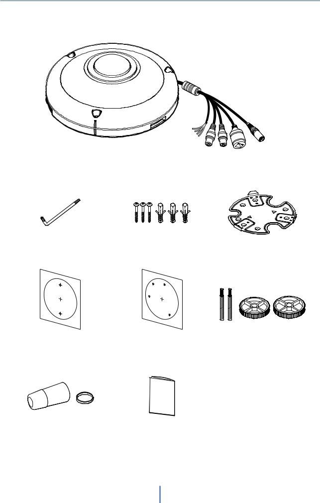
Product and Accessories
Camera |
Cables |
Hex Allen Wrench |
Screws and |
Mounting Plate |
|
Plastic Anchors - 3pcs |
|
|
|
Mounting Template |
Mounting Template for |
Mounting Bolts |
|
for Bolt and Nut |
Plate Installation |
||
and Nuts |
|||
Installation |
|
||
|
|
Waterproof Cap and |
Quick Setup and |
Gasket |
Installation Guides |
5

Introduction -
Part Names
Illumination Sensor Hall
Dome Cover
Window Cover
Illumination Sensor |
Fisheye Lens |
SD Card Slot
Reset Button
Alarm In/Out |
Audio In/Out
DC Power Jack
RJ-45 Connector
Waterproof Cap
Mounting Plate
Plate Hook
6
Installation -
Disassembling the Camera
Before installing your camera, you have to read the following cautions.
1.The mounting surface must withstand fve times the camera weight.
2.Do not let the cables get caught in improper places or the electric line cover can be damaged. This may cause a short or fre.
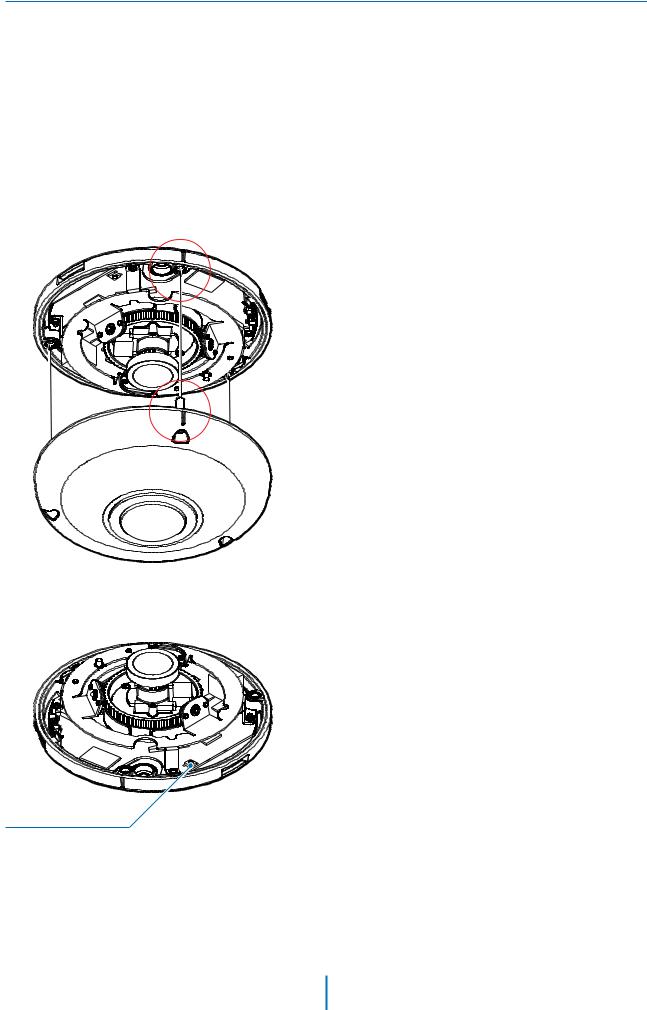
3.For the installation process, remove the camera cover from the camera module by loosening the three (3) screws on the dome. Use the wrench provided with the camera.
The camera includes a sensor at the camera module. For the sensor to function properly, the camera’s cover includes a special sensor hole.
 When assembling the camera together, please make sure the sensor hole in the camera’s cover is aligned with the sensor in the camera module.
 When placing the cover back on the camera, also make sure to align the cover and bottom case to match the case outline.
 Reset to the Factory Default
Press the reset button for 5 seconds to return the setup to the factory default.
 Warning:
If you press the ‘Reset’ button, you will lose all setting data. If needed, please, make a note for further installation.
Reset Button
7
Installation -
Basic Installation
Mounting Template
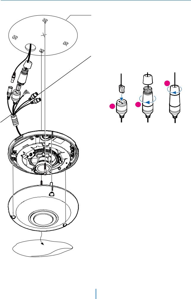
1. Using the mounting template sheet or the camera itself, mark and drill the necessary holes in the wall or ceiling.
2. Pass the wires through the mount bracket and make all necessary connections. See page 12 for more information.
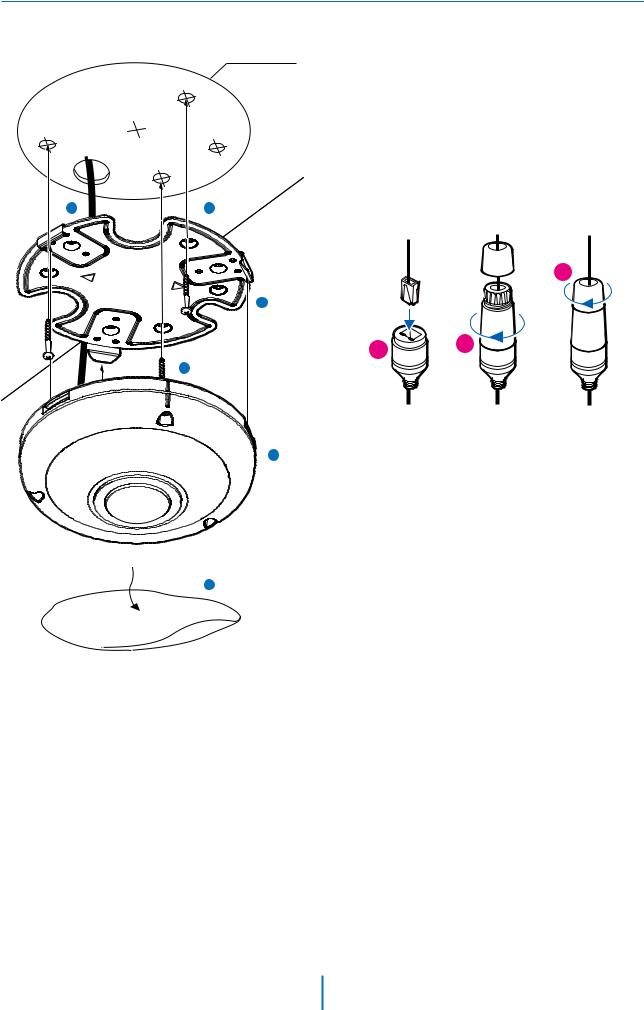
3. To use the camera’s waterproof wiring: a. Install the LAN cable into (a) .
b. (b) will be assembled to (a) with a 1/4 turn. c. Thread (c) tightly to (b).
c
a |
b |
 NOTE: to ensure a proper moisture seal, make sure the o-ring is in place between (a) and (b). In extreme environments, use an outdoor-rated sealer.
 NOTE: When using the waterproof cap, crimp the RJ-45 connected after passing the camera through the waterproof cap.
4. Attach the camera to the mounting surface using the included anchors and screws.
5. Assemble the cover over the camera body. Be sure to assemble the cover and bottom case to match the case outline.
6. When the installation is completed, remove the protective film.
8
Installation -
Installation Using Mounting Plate
Template Sheet
3 |
2 |
5
4
6
7
1.Using the mounting template sheet for the metal plate, or the metal plate itself, mark and drill the necessary holes in the wall or ceiling.
2.Pass the wires through the mount bracket and make all necessary connections. See page 12 for more information.
3.To use the camera’s waterproof wiring:
a.Install the LAN cable into (a) .
b.(b) will be assembled to (a) with a 1/4 turn.
c.Thread (c) tightly to (b).
c
a |
b |
 NOTE: to ensure a proper moisture seal, make sure the o-ring is in place between (a) and (b). In extreme environments, use an outdoor-rated sealer.
 NOTE: When using the waterproof cap, crimp the RJ-45 connected after passing the camera through the waterproof cap.
4.Mount the metal plate to the mounting surface using the included screws.
5.Assemble the cover over the camera body. Be sure to assemble the cover and bottom case to match the case outline.
6.Fix the camera's bottom case to the metal plate. Press the three (3) bezels on the bottom care of the camera until it snaps to the metal plate. A snap sound will confirm the camera base is properly locked into the mounting plate.
7.When the installation is completed, remove the protective film.
9
Installation -
Installation Using Mounting Bolts and Nuts
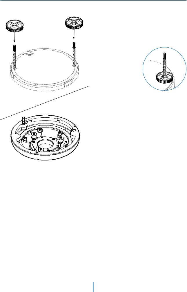
1. Using the mounting template for the nuts and bolts installation, mark and drill the necessary holes in the wall or ceiling.
2. Pass the wires through and make all necessary connections. See page 12 for more information.
3. Secure the two long mounting screws to the camera’s base.
4. Mount the camera to the mounting surface using
the 2 mounting nuts. 


5. Rotate the locking discs over the screws
until the camera is held tightly from the mounting surface.
6. Adjust the camera’s lens 
 position to the necessary
  angle. the camera’s max tilting angle is 75°.
7. Assemble the dome cover over the camera body. Be sure to assemble the dome and bottom case to match the case outline.
8. When the installation is completed, remove the protective film.
10
Installation -
Cabling
Two Options
Use a PoE-enabled switch to connect data and power through a single cable and begin viewing and recording images instantly.
A non-PoE switch will require an adaptor for power transmission.
1. Using a PoE-Enabled Switch
The Camera is PoE-compliant, allowing transmission of power and data via a single Ethernet cable.
PoE eliminates the need for the different cables used to power, record, or control the camera. Follow the illustration below to connect the camera to a PoEenabled switch using an Ethernet cable.
2. Using a Non-PoE Switch
If a PoE-enabled switch is not used, use a power adaptor for power transmission and non-PoE switch for data transmission.
Follow the illustrations below to connect the camera without a PoE-enabled Switch.
Ethernet cable |
Ethernet cable |
Power
11
Installation -
Cabling
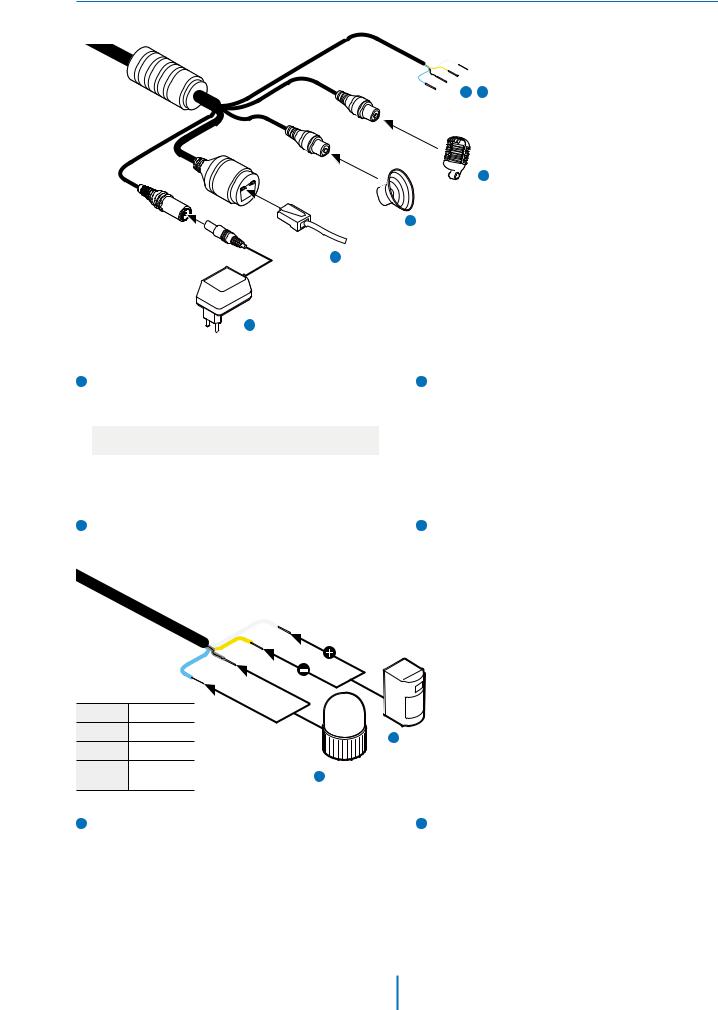
4 5 Alarm In/Out
4 Audio Input
3 Audio Output
2 Network
1 Power
1Power Connection
Please, check the voltage and current capacity of
rated |
power carefully. |
||
|
|
|
|
|
Rate Power |
Power |
PoE |
|
Consumption |
||
|
|
|
|
|
|
|
|
|
DC 12V |
8.5W |
IEEE 802.3af |
|
class3, max 10W |
||
|
|
|
|
3Audio Output
Connect the ‘audio out’ port of the camera to the ‘line in’ port of the speaker.
 If the speaker without the amplifier is connected to the audio out port, it doesn’t work properly. Therefore, the speaker with the amplifier or the separate amplifier is needed.
 Audio Out is available via the RTSP backchannel.
2Network Connection
Connect the crossover cable into the RJ-45.
4Audio Input
Connect the ‘audio in’ port of the camera to the microphone directly or 'line out’ port of the amplifier connected with a microphone.
 If the microphone is connected directly, the microphone with the embedded amplifier such as condenser mic. needs to be used.
DI (+) |
WHITE |
|
|
|
DI (-) |
YELLOW |
|
6 Alarm Input |
|
DO (-) SKY BLUE |
|
|||
|
|
|||
DO (+) |
GRAY + |
5 |
Alarm Output |
|
DOT |
||||
|
|
|
||
5Alarm/Relay Out (DO)
Connects to the alarm lights, siren or lamps and the sensor types are normally open and normally close.
6Sensor/Alarm Input (DI)
The sensor/alarm input device's cable should connect to + and - of the Terminal Block.
12
Installation -
Managing the SD Card
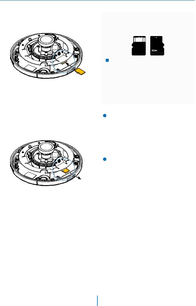
The memory card is an external data storage device that has been developed to offer an entirely new way to record and share video, audio, and text data using digital devices.
Micro
 Recommended SD card specification (not included)
- Type: Micro SD (SD/SDHC/SDXC) - Manufacturer: SanDisk, Samsung,
Transcend, Micron
- Capacity: 4GB~128GB
- Class: UHS-I U3 Class 10
 New micro SD card over 64GB must be formatted on the first use.
1 Inserting an SD Memory Card
Insert the SD card in the arrow direction.  Don’t insert the SD memory card while it’s
upside down by force. Otherwise, it may damage the SD memory card.
2 Removing an SD Memory Card
Removing an SD Memory Card Gently press down on the exposed end of the memory card as shown in the diagram to eject the memory card from the slot.
 Pressing too hard on the SD memory card can cause the card to shoot out uncontrollably from the slot when released.
 If you have saved data in the SD memory card, removing the SD memory card before setting the record to OFF will cause damage to the data stored in the card.
13
Network setup -
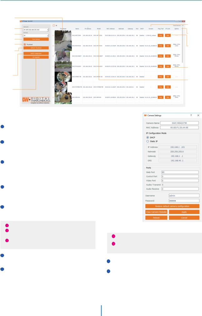
DW IP FinderTM
Thumbnail view |
|
|
Select network to scan |
Firmware version |
|
Camera's uptime |
||
Filter device type to scan |
||
Scan devices |
|
|
Show/hide |
Open device |
|
thumbnail view |
||
configuration |
||
Refresh thumbnail view |
||
settings |
||
|
||
Bulk IP assignment |
Device's |
|
|
information |
|
Firmware upgrade |
|
1Go to: http://www.digital-watchdog.com and search for ‘IP Finder’ on the quick-search bar at the top of the page.
2The latest IP Finder software will appear in the search results. Click on the link to download the file to your computer.
3The software will scan your network for all supported cameras and display the results in the table. Allow up to 5 seconds for the IP Installer to find the camera on the network.
4You can press the ‘Refresh List’ to search the network again, or filter the search results by entering a value in the filter box.
5Check the box next to ‘Display Camera Thumbnail’ to view a JPEG image of the camera’s view next to the camera name on supported models.
i The default network type of camera is DHCP mode.
i If you have a DHCP server, it will automatically set the Camera IP.
iContact your network administrator for more information.
6To save the changes made to the camera's settings, input ID and PW of the camera for authentication.
7If the camera needs to be rebooted after the settings were changed, press the 'Reboot' button. The camera will power cycle and will appear back in the search results once the reboot is complete.
i Default ID / PW : admin / admin
i For security purposes, it is highly recommended to change your password after initial setup.
8 Click 'Save' to save changed values.
9To update the camera's firmware from the DW IP FinderTM, click on the firmware tab, upload the firmware file and select the camera to update. You can update multiple cameras at the same time.
14
Web Viewer Screen -
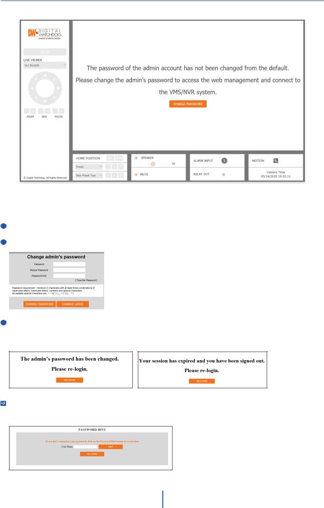
Basic Screen (Default)
Password change is required at the initial connection in a factory reset state.
1 You cannot see the image, and the setup button is disabled.
2 Change the password with the CHANGE PASSWORD button.
3After changing the password, login again by pressing the RE-LOGIN button.
•Internet Explorer: After three failed attempts or the cancel button is clicked, you will experience a login fail.
•Other Browsers: After the Cancel button is clicked, you will experience a login fail.
Password Hint Page
•If you need help remembering the password for your user, input the username in the username field and press the hint button. If you added a hint for your password when setting it up, it will appear then.
15
Web Viewer Screen -
Basic Screen
1
2
3
4
5
6
7
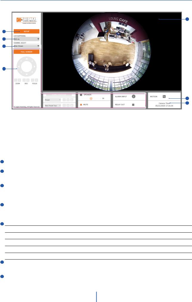
 The web viewer is optimized with Internet Explorer 10 (or above) and Mozilla Firefox.
 “If VLC is not installed or the VLC plugin is not supported (Chrome), ‘Live Buffering’ and ‘Channel Select’ (subjects 3 and 4 in the diagram) will display as ‘Live Viewer’. If so, select HTML5 (MJPEG) from the Live Viewer menu to view the video.
1 Live video display. This is the region for the live video stream from the camera.
2Setup a popup button. Click it to open the Setup page to setup details of IP camera like Video, Network, Events, System, etc. See the section ‘Setup’.
3When the image is not smooth due to a bad network connection, it stored image during setup time and shows the image on the live view screen.
 Users will see the delayed images based on the set delay time.
4Channel Select button. Select a stream produced from the camera between Stream 1 ~ 3 to display it in the live
view screen.
 Refer the ‘Setup > Video & Audio > Video’ to setup the Video Stream.
5Below “Menu” is supported per models.
PTZ Control - This camera model does not support the zoom and focus. Preset - Not supported.
Speaker Control - Enable/disable the audio stream from the camera and adjust the volume accordingly. Alarm Input - If an alarm is triggered, the corresponding input number will be changed from dark gray to red. Relay Out - Using this checkbox, read the relay output status and set or reset it manually.
6Motion - Shows the motion event status.
 Event Alert Icon (
  ) appears if ‘Motion Detection’ is activated.
7Camera Time - Display the camera time.
16
Setup - Video & Audio Setup
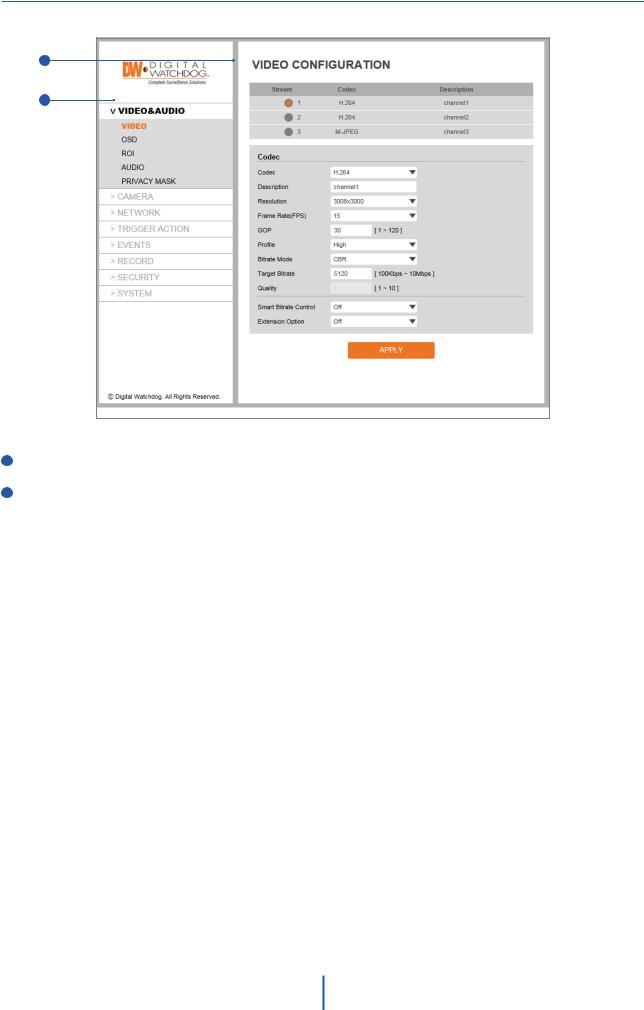
Video Configuration
1
2
1 Detail Page - When you select an item from the menu, you can set the details for the selected item.
2Setup Constitution
Video&Audio
[ VIDEO, OSD, ROI, AUDIO, PRIVACY MASK ]
Camera
[ IMAGE ADJUSTMENT, EXPOSURE, DAY&NIGHT, BACKLIGHT, WHITE BALANCE, IMAGE, VIDEO ]
Network
[ STATUS, NETWORK SETTING, AUTO IP, ONVIF, UPNP, DDNS, FTP, SMTP, SNMP, RTSP INFORMATION ]
Trigger Action
[ ACTION RULES, IMAGE TRANSFER, RELAY OUT ]
Events
[ EVENT RULES, MOTION, TEMPERATURE, ALARM ]
Record
[ MANAGEMENT, RECORD LIST, STORAGE ]
Security
[ IP ADDRESS FILTER, RTSP AUTHENTICATION, IEEE 802.1x, HTTPS, CERTIFICATES, SERVICE ]
System
[ INFORMATION, DIAGNOSTICS, FIRMWARE UPDATE, DATE&TIME, DST, USER MANAGEMENT, LOG, LANGUAGE, FACTORY RESET, RESTART, OPEN SOURCE ]
17
Setup - Video & Audio Setup
Video Configuration
1
2
3
4
5
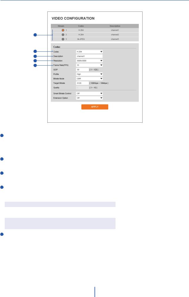
1Live Video Channel Setup - The video can be configured to various settings with a combination of codec and resolution. The camera performance should be considered when setting multiple channels, as the performance of the camera will be affected.
 H.265 (HEVC) codec with higher bitrate may cause unstable live streaming or reload the webpage.
2Codec - Choose the video codec. Depending on the selected codec, the subcategories may be changed accordingly.
3Description - Input the additional description of the selected channel. Max. 30 alpha-numeric characters may be used, including spaces.
4Resolution - Select video resolution.
 Available Frame Rate may differ even if the same codecs are in use. <Resolution of Video Format>
|
3K x 3K |
7.8M |
2.6M |
0.4M |
0.1M |
|
NTSC |
3008 x |
2800 x |
1600 x |
640 x |
320 x |
|
3000 |
2800 |
1600 |
640 |
320 |
||
|
||||||
|
|
|
|
|
|
|
PAL |
3008 x |
2800 x |
1600 x |
640 x |
320 x |
|
3000 |
2800 |
1600 |
640 |
320 |
||
|
||||||
|
|
|
|
|
|
5Frame Rate - Select the maximum Frame Rate.
 Available Frame Rate can be di erent although the same codecs were set up.
18
Setup - Video & Audio Setup
Video Configuration
6
7
8
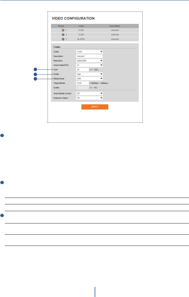
6GOP(Group of Pictures) Size - Set up the number of frames (P-frame) which contain only changed information based on the basic frame (I-frame). Regarding videos with lots of movement, if you set GOP size bigger, only the number of P-frames is bigger.
As a result, the video resolution will be low but ‘File size’ and ‘Bit-rate can be decreased.
 GOP(Group of Pictures) Size -
I-frame and P-frame creation for MPEG4, H.264, and H.265 (HEVC) video compression. ‘I-frame’, also known as ‘key-frame’, refers to the complete image data for a specific video frame. ‘P-frame’ refers to the changes in the image in comparison to the previous video frame. As a result, the GOP consists of one I-frame and several P-frames. For improved video quality, use a lower number of P-frames for this setting.
7Profile - The profile defines the subset of bitstream features in H.264, H.265 (HEVC) stream, including color reproduction and additional video compression.
 H.264: Main, High / H.265 (HEVC): Main
Main - An intermediate profile with a medium compression ratio. Supports I-frames, P-frames, and B-frames.
High - A complex profile with a high compression ratio. Supports I-frames, P-frames, and B-frames.
8Bitrate Mode - Select the bit rate control scheme of video compression from CBR (Constant Bit Rate) or VBR (Variable Bit Rate).
CBR - To guarantee the designated constant bit rate, the quality of the video is controlled in this mode. Therefore, the quality of the video is likely to be varying when network tra c is changing.
VBR - To guarantee the designated quality, the bit rate of the video stream is changed in this mode. Therefore, the frame rate of the video is likely to be varying when network tra c is changing.
 This category will not appear if you select the codec.
19
Setup - Video & Audio Setup
Video Configuration
9
10
11
12
13
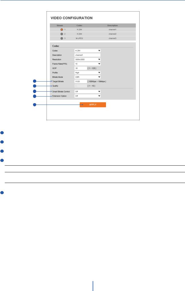
9 Target Bitrate - If Bitrate Control is set to be CBR, you can set the Target Bitrate.
10 Quality - For VBR control mode, The Target Quality of video can be setup.
11 Smart Core - Off / Smart.RC
12Extension Option
O - You cannot use the Extension Option.
SVC-T On - The H.264, H.265 (HEVC) SVC (Scalable Video Coding) is a video compression algorithm that enables e ective and e cient transmission of video files over low bandwidth networks.
13Click ‘Apply’ to save all settings.
20
Setup - Video & Audio Setup
OSD Configuration
1
2
3
1 Date / Time - Display the current time.
2User Text - Output the TEXT entered by the user. Support a maximum of 30 characters.
3Click ‘Apply’ to save all settings.
21
Setup - Video & Audio Setup
Region of Interest Configuration
1
2
3
4
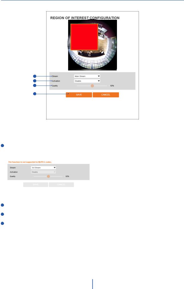
The region of interest function gives a more efficient picture quality for the indicated area to improve the qualities of movement in the scene without compromising the bandwidth.
1 Stream - Select the Stream.
 Currently supports only H.264, H.265 (HEVC).
 The function is not supported in the MJPEG codec.
2Activation - Enable or disable the region of interest function.
3Quality - Set the quality of the set area.
4Click ‘Save’ to save all settings.
 Click 'Cancel' to return to the previous setting.
22
Setup - Video & Audio Setup
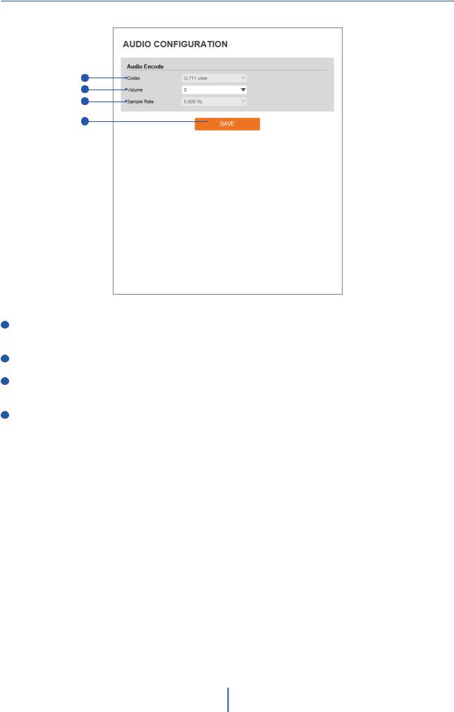
Audio Configuration
1
2
3
4
1Codec - Select the Audio Codec.
 Currently, the camera supports codec G.711.
2Volume - Select the Audio Volume from 0 to 10.
3Sample Rate - Select the Audio Sample Rate.  Currently, the camera supports 8000 Hz.
4Click ‘Save’ to save all changes.
23
Setup - Video & Audio Setup
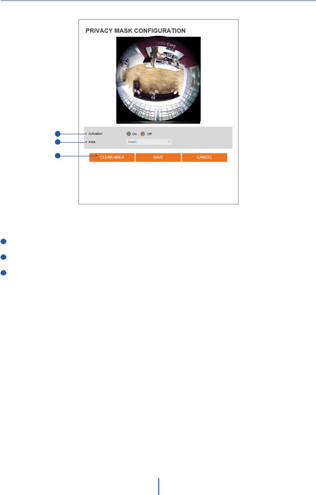
Privacy Mask Configuration
1
2
3
Use this function to mask areas that you want to hide on-screen to protect privacy.
1 Activation - Enable or disable the privacy mask function.
2Area - Select the Area1 ~ Area16 and Set the privacy area.
3Click ‘Save’ to save all settings.
 Click 'Cancel' to return to the previous setting.
 Click ‘Clear Area' to delete the selected Area1~Area16.
24
Setup - Camera Setup
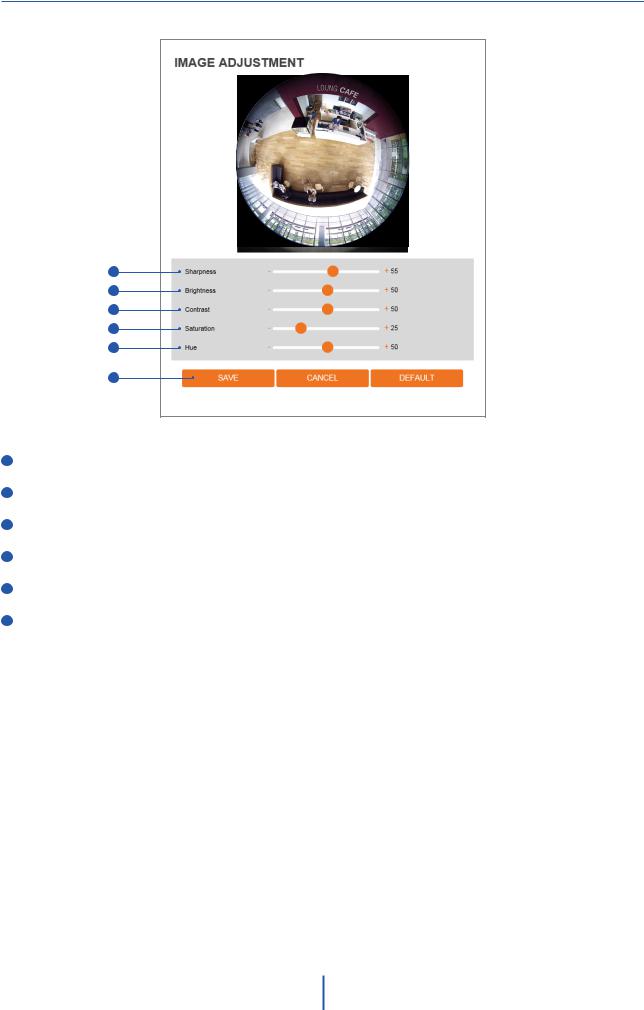
Camera Image Adjustment
1
2
3
4
5
6
1 Sharpness - The higher the number, the sharper the lines in the image will appear.
2Brightness - The higher the number, the brighter the image will appear.
3Contrast - The higher the number, the stronger the contrast between colors in the image will appear.
4Saturation - The higher the number, the more saturated the colors in the image will appear.
5Hue - The higher the number, the stronger the hue in the image will appear.
6Click ‘Save’ to save all settings.
 Click 'Cancel' to return to the previous setting.
 Click 'Default' to settings to the factory defaults.
25
Setup - Camera Setup
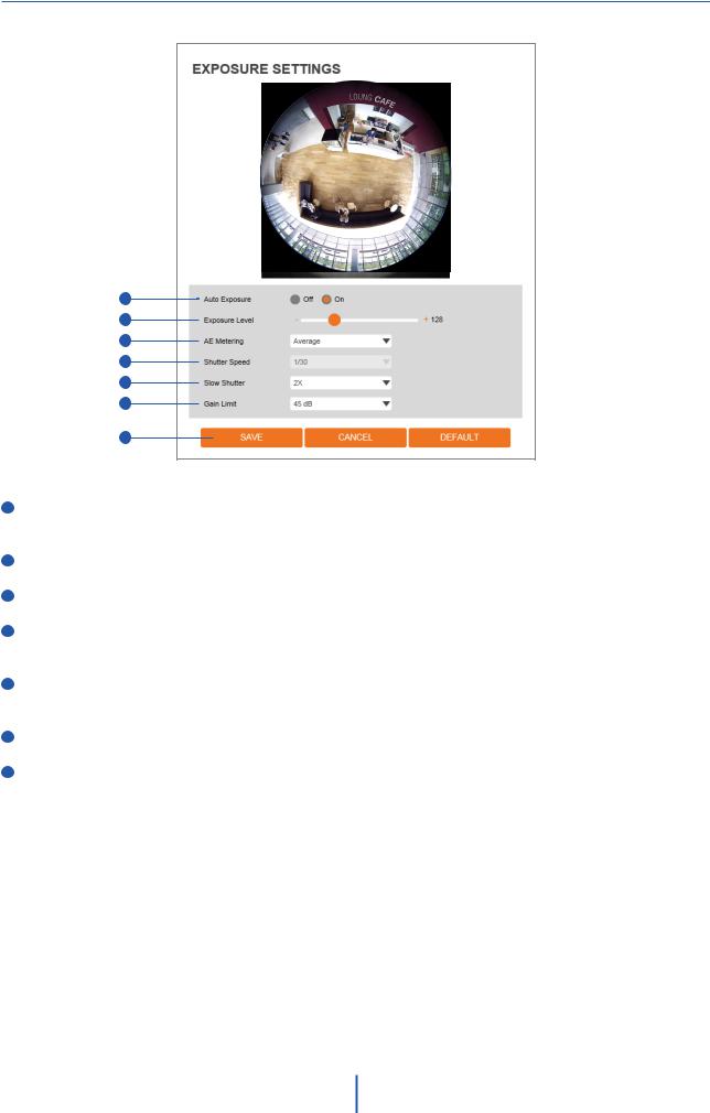
Camera Exposure Settings
1
2
3
4
5
6
7
1Auto Exposure - Automatic exposure (AE) automatically sets the aperture or shutter speed, based on the external lighting conditions for the photo.
2Exposure Level - The higher the number, the brighter the image will appear.
3AE metering - AE metering mode refers to how a camera determines the exposure.
4Shutter Speed - If this speed is faster, the moving object can be photographed without the ghost effect. However, the picture can be dark if the lighting is insufficient.
5Slow Shutter Level - Slow shutter Level lets you adjust the amount of light striking the sensor and essentially determines when the video sensor sends out its batch of data for processing.
6Gain Limit - The smaller number makes the darker image.
7Click ‘Save’ to save all settings.
 Click 'Cancel' to return to the previous setting.
 Click 'Default' to settings to the factory defaults.
26
 Loading...