

Page 1

DEWALT Industrial Tool Co., 701 East Joppa Road, Baltimore, MD 21286 Printed in U.S.A. (JAN98-CD-1) Form No. 385103
DW751 Copyright © 1998
DW751/385103 5/2/02 12:51 PM Page 2
Page 2

INSTRUCTION MANUAL
GUIDE D'UTILISATION
MANUAL DE INSTRUCCIONES
DW751
Drill Bit Sharpener
Affûte-foret
Afilador de brocas
INSTRUCTIVO DE OPERACIÓN, CENTROS DE SERVICIO Y PÓLIZA
DE GARANTÍA. ADVERTENCIA: LÉASE ESTE INSTRUCTIVO ANTES
DE USAR EL PRODUCTO.
Questions? See us on the World Wide Web at www.dewalt.com
DW751/385103 5/2/02 12:51 PM Page 3
Page 3
Important Safety Instructions
WARNING: When using electric tools, basic safety precautions
should always be followed to reduce risk of fire, electric shock, and
personal injury, including the following:
READ ALL INSTRUCTIONS
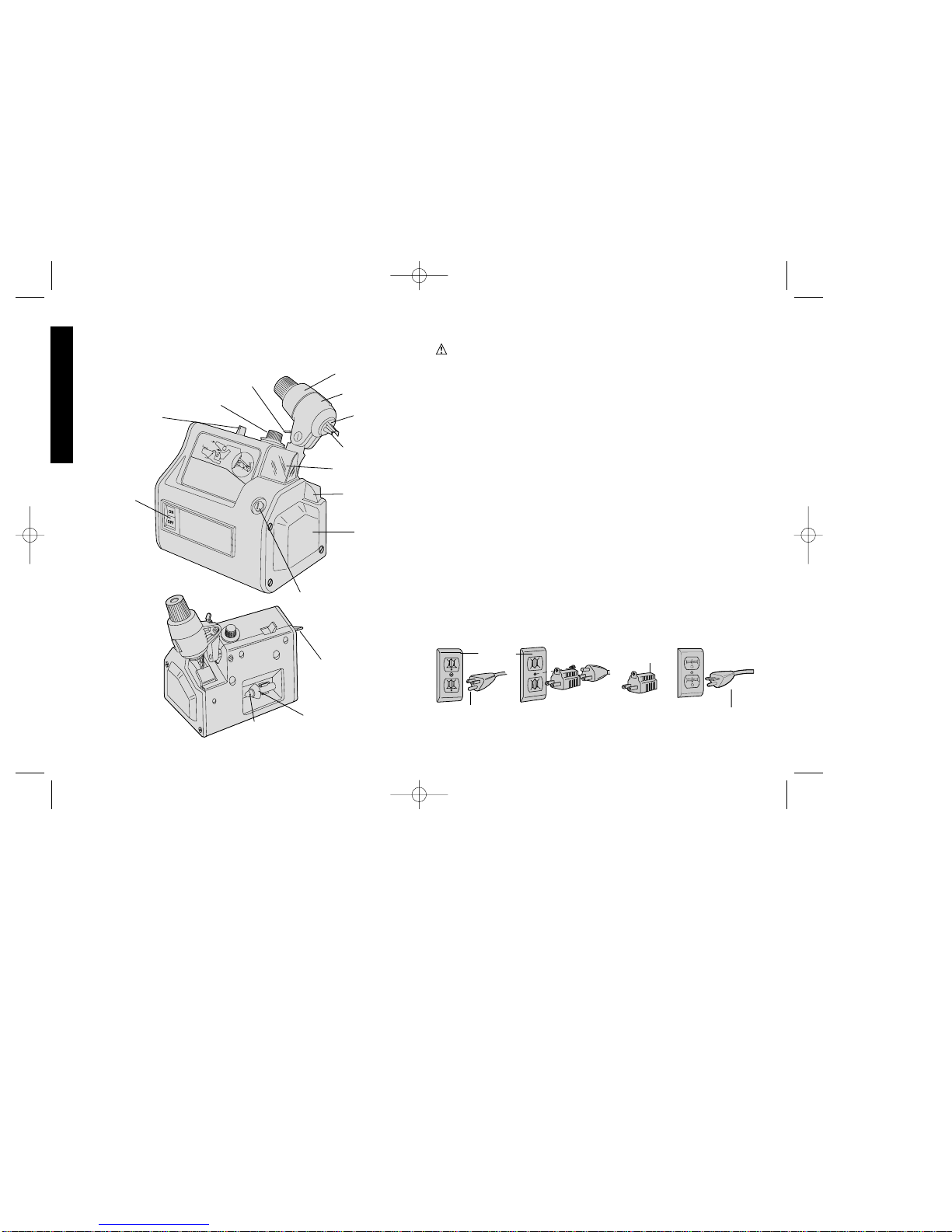
Grounding Instructions
This tool should be grounded while in use to protect the operator from
electric shock. The tool is equipped with a 3-conductor cord and 3prong grounding type plug to fit the proper grounding type receptacle.
The green (or green and yellow) conductor in the cord is the
grounding wire. Never connect the green (or green and yellow) wire
to a live terminal. If your unit is intended for use on less than 150 V,
it has a plug that looks like that shown in sketch A. If it is for use on
150 to 250 V, it has a plug that looks like that shown in sketch D. An
adapter, sketches B and C, is available for connecting sketch A type
plugs to 2-prong receptacles. The green-colored rigid ear, lug, or the
like, extending from the adapter must be connected to a permanent
ground, such as a properly grounded outlet box. No adapter is
available for a plug as shown in sketch D. ADAPTER SHOWN IN
FIGURES B and C IS NOT FOR USE IN CANADA.
English
IF YOU HAVE ANY QUESTIONS OR COMMENTS ABOUT THIS
OR ANY D
EWALT TOOL, CALL US TOLL FREE AT:
1-800-4-DEWALT (1-800-433-9258)
S
H
A
R
P
E
N
I
N
G
IN
S
T
R
U
C
T
I
O
N
S
S
W
IN
G
H
E
A
D
M
O
D
E
S
E
L
E
C
T
O
R
F
E
E
D
K
N
O
B
L
O
A
D
P
U
S
H
L
A
T
C
H
G
R
IN
D
T
O
1
/3
2"
ENTIRE
LOCATOR EDGE
TOUCHING
FLUTE
SHARPEN/DRESS
SELECTOR
FEED KNOB
INDEX SLEEVE
SWINGHEAD
CHUCK
LOCATOR
GRINDING
WHEEL
LATCH
EYE SHIELD
WHEEL
COVER
DRESS KNOB
DUST SHIELD
DIAMOND
DRESSER
GUARD BAND
ADJUSTMENT
SCREW
ON/OFF
MOTOR
SWITCH
AB CD
GROUNDING PIN
GROUNDED
OUTLET
BOX
GROUNDING
MEANS
GROUNDING PIN
ADAPTER
DW751/385103 5/2/02 12:51 PM Page 4
Page 4

Safety Instructions For All Tools
• KEEP WORK AREA CLEAN. Cluttered areas and benches invite
injuries.
• CONSIDER WORK AREA ENVIRONMENT. Don’t expose power
tools to rain. Don’t use power tools in damp or wet locations. Keep
work area well lit. Do not use tool in presence of flammable liquids
or gases.
• GUARD AGAINST ELECTRIC SHOCK. Prevent body contact
with grounded surfaces. For example; pipes, radiators, ranges, and
refrigerator enclosures.
• KEEP CHILDREN AWAY. Do not let visitors contact tool or
extension cord. All visitors should be kept away from work area.
• STORE IDLE TOOLS. When not in use, tools should be stored in
dry, and high or locked-up place — out of reach of children.
• DON’T FORCE TOOL. It will do the job better and safer at the
rate for which it was intended.
• USE RIGHT TOOL. Don’t force small tool or attachment to do the
job of a heavy-duty tool. Don’t use tool for purpose not intended.
• DRESS PROPERLY. Do not wear loose clothing or jewelry. They
can be caught in moving parts. Rubber gloves and non-skid
footwear are recommended when working outdoors. Wear
protective hair covering to contain long hair.
• USE SAFETY GLASSES. Also use face or dust mask if cutting
operation is dusty.
• DON’T ABUSE CORD. Never carry tool by cord or yank it to
disconnect from receptacle. Keep cord from heat, oil, and sharp
edges.
• SECURE WORK. Use clamps or a vise to hold work. It’s safer than
using your hand and it frees both hands to operate tool.
• DON’T OVERREACH. Keep proper footing and balance at all
times.
• MAINTAIN TOOLS WITH CARE. Keep tools sharp and clean for
better and safer performance. Follow instructions for lubricating
and changing accessories. Inspect tool cords periodically and if
damaged, have repaired by authorized service facility. Inspect
extension cords periodically and replace if damaged. Keep
handles dry, clean, and free from oil and grease.
• DISCONNECT OR LOCK OFF TOOLS when not in use, before
servicing, and when changing accessories, such as blades, bits,
cutters.
• REMOVE ADJUSTING KEYS AND WRENCHES. Form habit of
checking to see that keys and adjusting wrenches are removed
from tool before turning it on.
• AVOID UNINTENTIONAL STARTING. Don’t carry tool with finger
on switch. Be sure switch is off when plugging in.
• EXTENSION CORDS. Use only 3-wire extension cords that have
3-prong grounding-type plugs and 3-pole receptacles that accept
the tool’s plug. Replace or repair damaged cords. Make sure your
extension cord is in good condition. When using an extension cord,
be sure to use one heavy enough to carry the current your product
will draw. An undersized cord will cause a drop in line voltage
resulting in loss of power and overheating. The following table
shows the correct size to use depending on cord length and
nameplate ampere rating. If in doubt, use the next heavier gage.
The smaller the gage number, the heavier the cord.
Minimum Gage for Cord Sets
Volts Total Length of Cord in Feet
120V 0-25 26-50 51-100 101-150
240V 0-50 51-100 101-200 201-300
Ampere Rating
More Not more American Wire Gage (AWG)
Than Than
0-6 18 16 16 14
6 - 10 18 16 14 12
10 - 12 16 16 14 12
12 - 16 14 12 Not Recommended
1
English
DW751/385103 5/2/02 12:51 PM Page 1
Page 5

2
• OUTDOOR USE EXTENSION CORDS. When tool is used
outdoors, use only extension cords intended for use outdoors and
so marked.
• STAY ALERT. Watch what you are doing. Use common sense. Do
not operate tool when you are tired.
• CHECK DAMAGED PARTS. Before further use of the tool, a guard
or other part that is damaged should be carefully checked to
determine that it will operate properly and perform its intended
function. Check for alignment of moving parts, binding of moving
parts, breakage of parts, mounting, and any other conditions that
may affect its operation. A guard or other part that is damaged
should be properly repaired or replaced by an authorized service
center unless otherwise indicated elsewhere in this instruction
manual. Have defective switches replaced by authorized service
center. Do not use tool if switch does not turn it on and off.
Additional Safety Rules for Drill Bit
Sharpener
WARNING: This professional tool is designed for fast, accurate
sharpening of right-hand, 2-flute twist drill bits from 1/8" (3 mm) to
1/2" (13 mm) in diameter. DO NOT attempt to sharpen carbidetipped or cobalt bits. Since proper procedure is essential to
satisfactory results, read the operating instructions carefully, and,
for your own protection, pay close attention to the safety rules.
• Wear eye protection.
• Use grinding wheel suitable for speed of grinder.
• Replace cracked wheel immediately. Handle grinding wheels
carefully to avoid bumping or dropping. DO NOT use a grinding
wheel that has been dropped. Before using, inspect each grinding
wheel for cracks or flaws and if these are evident, discard the
wheel.
• Always use guards and eye shields. Keep the eye shield mounted
in proper positions.
• Do not overtighten wheel nut. Before mounting a new wheel, be
sure that it is marked with an R.P.M. that is the same as, or higher
than, the no-load speed of the tools as marked on the nameplate.
• Use only flanges furnished with the grinder.
• Bolt the drill bit sharpener to a bench to prevent movement.
• Adjust distance between wheel and guards to maintain 1/16" (1.6
mm) or less separation as the diameter of the wheel decreases
with use.
• Use accessories only in proper and intended manner.
SAVE THESE INSTRUCTIONS
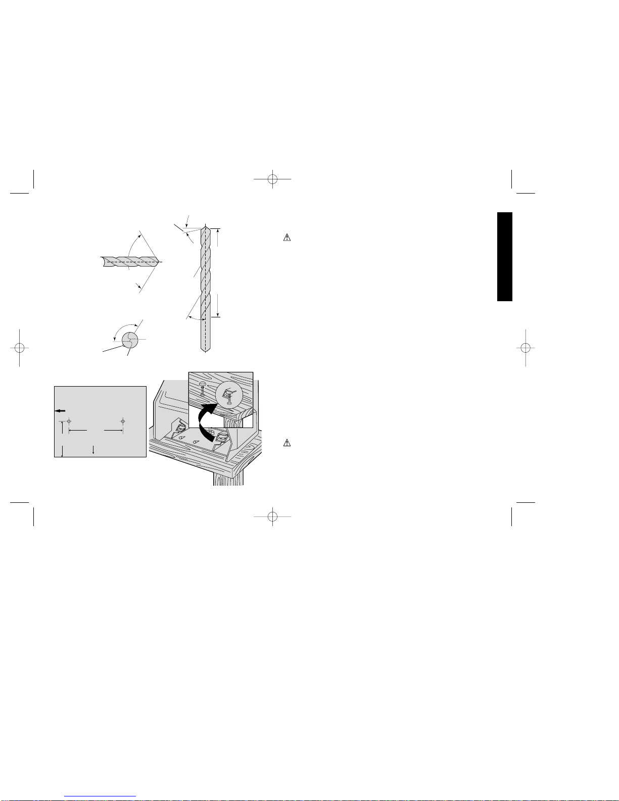
Drill Bit Terminology
A primary requirement for drilling accurately sized holes is that there
be minimal difference between the lip heights of the two flutes.
Variations in the two lip heights will alter the centrality of the point
which will produce eccentric drilling. (See Figures 1, 2, and 3.) See
paragraph 6 of the “Troubleshooting” section in this manual. Your
D
EWALT sharpener is engineered to produced equal lip heights and
a centrally located point.
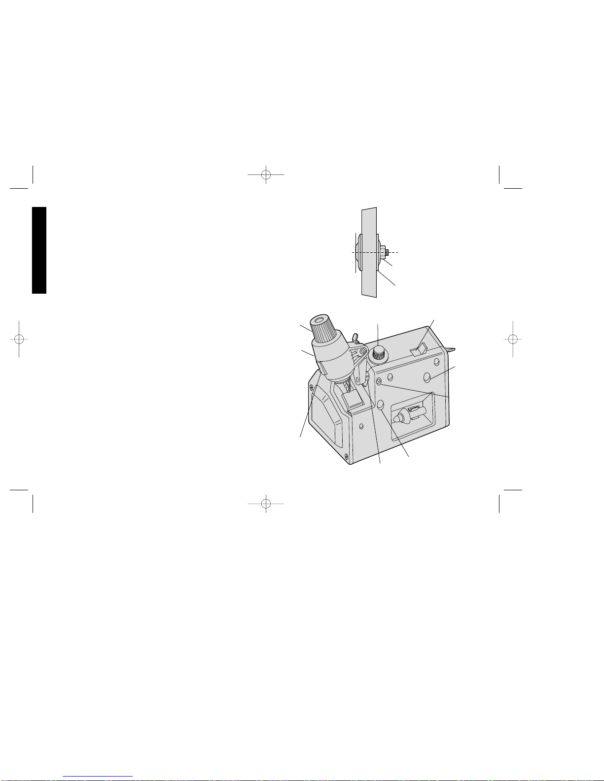
Mounting the Sharpener
FOR BEST RESULTS YOUR SHARPENER SHOULD BE
MOUNTED TO A FIRM WORK SURFACE. Drill two 5/16" (8 mm)
holes in work bench as shown in Fig. 4. Insert two 1/4" (6 mm)
diameter carriage bolts. Slide Sharpener over bolt heads and fit bolt
heads into openings provided in bottom of tool (Fig. 5.) Tighten nuts
on bolts evenly with moderate force. Do not overtighten!
English
DW751/385103 5/2/02 12:51 PM Page 2
Page 6
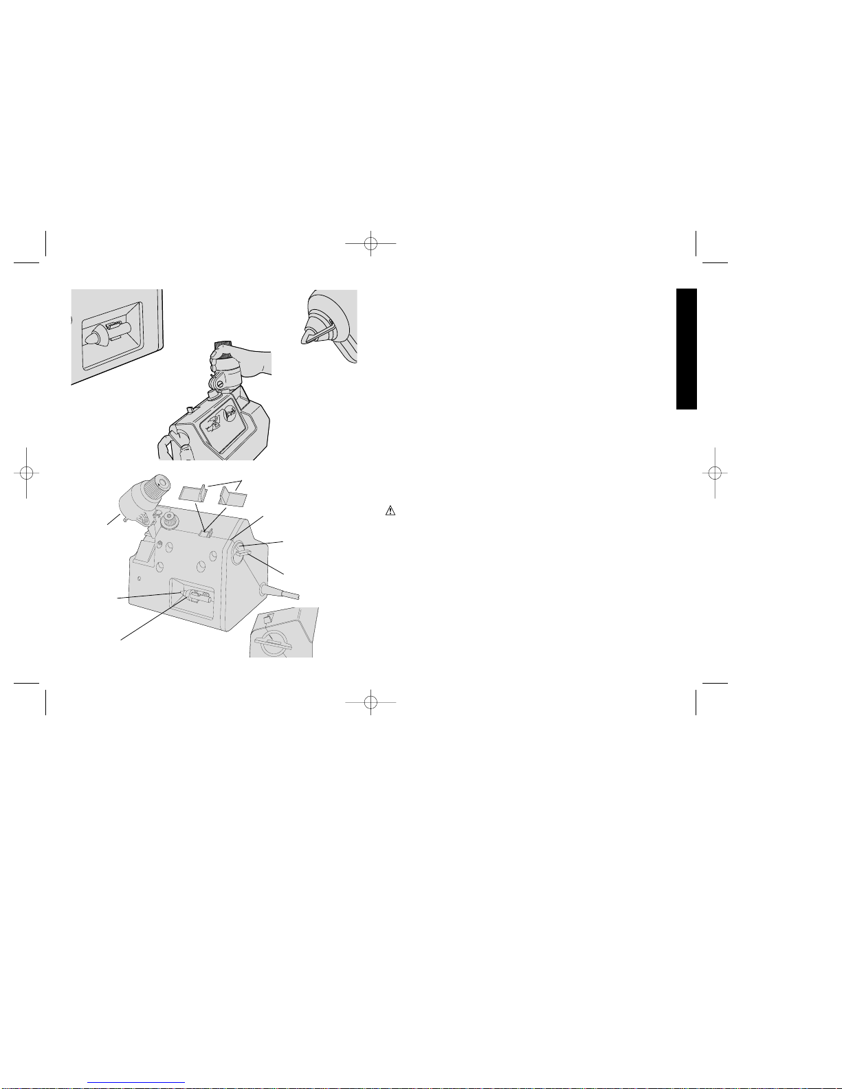
Main Functional Parts of Your Drill Bit
Sharpener
CAUTION:
• Play it safe—know all follow all SAFETY RULES.
• Be sure locator is clear of grinding wheel before starting motor.
• Use light pressure and an even motion in rocking the swinghead
when grinding.
• When shifting from BIT SHARPENING to WHEEL DRESSING—
and vice versa—follow instructions with extra care.
• Replace a cracked wheel immediately.
• Never disassemble the tool or try to do any rewiring in the electrical
system.
The Sharpen/Dress selector programs the tool for either bit
sharpening or wheel dressing. The Feed Knob provides precision
control of feed rate (material removal) during sharpening. The Index
Sleeve permits you to sharpen first one side of the drill bit tip, and
then the other side without removing the bit from the chuck. The
Swinghead lets you move the bit across the grinding wheel at the
correct angle repeatedly. The Chuck holds bit in position during
sharpening operation. The Locator guides positioning of drill bit so
that sharpening will be correct and accurate.
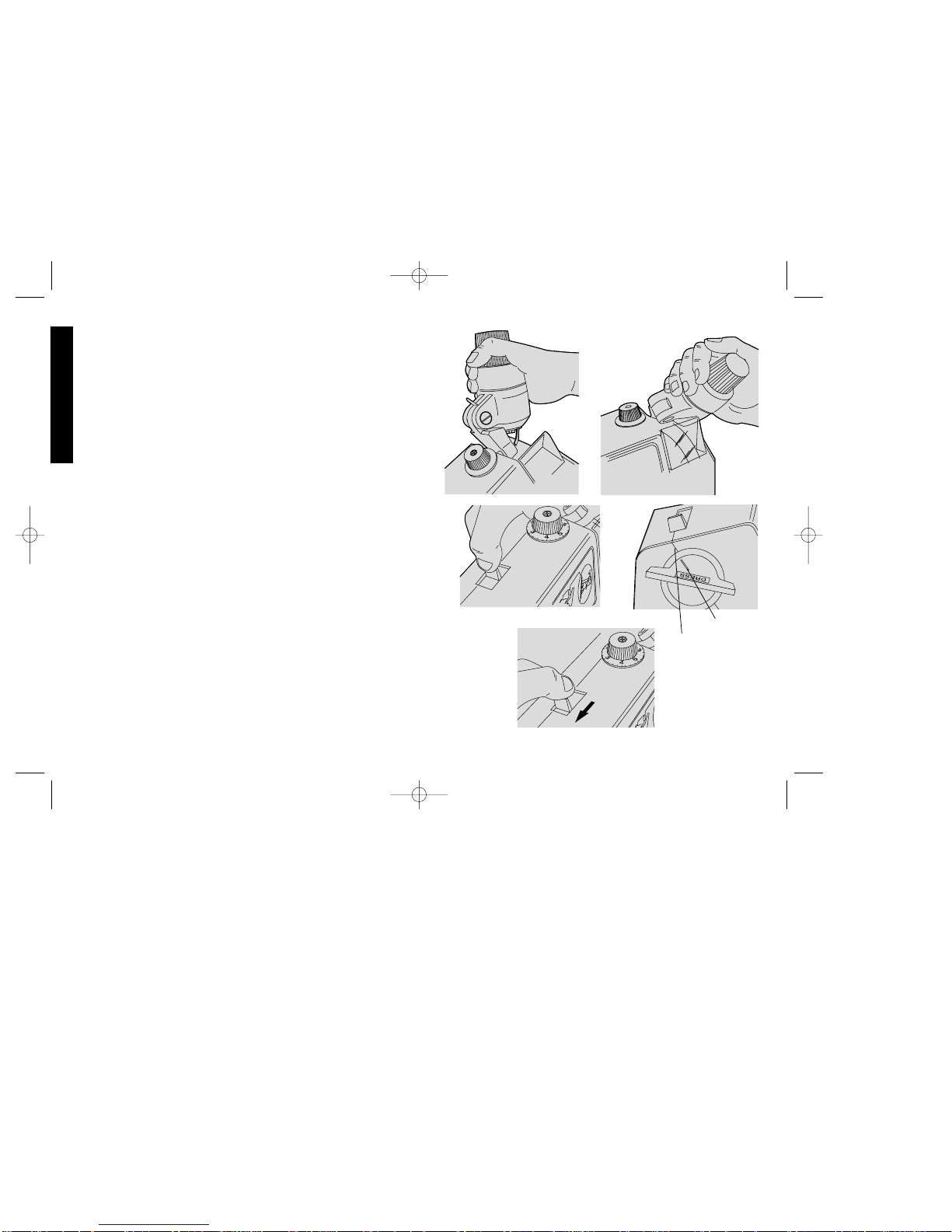
Shifting Selector Sharpen Bits or Dress
Wheel
(Figs. 6, 7, 8, 9, 10)
When you are ready to sharpen bits, the selector switch must be in
the “S” (sharpen) position. The “D” (dress) position is used when
dressing the grinding wheel.
IMPORTANT: Improper shifting from “D” (wheel dressing) to “S”
(bit sharpening), and vice versa, can cause damage and make your
sharpener inoperative. The correct methods of shifting are
illustrated.
3
English
FIG. 4
FIG. 1
FIG. 2
(122.2 mm)
Tool Outline
Front
(82.5 mm)
3 1/4"
4 13/16"
FIG. 5
HELIX
ANGLE
FIG. 3
120° TO 135°
CHISEL EDGE
ANGLE
INCLUDED ANGLE
OF POINT 118°
LIP RELIEF
ANGLE
FLUTE
FLUTE LENGTH
WEB
CUTTING
LIP
DW751/385103 5/2/02 12:51 PM Page 3
Page 7
4
SHIFTING FROM “S” (SHARPEN) TO “D” (DRESS)
NOTE: Be sure to do Step 1 before Step 2. Otherwise, the
swinghead will not move up to the eye shield.
1. Pivot swinghead to normal sharpening position (Fig.6).
2. Rotate swinghead until it touches the eyeshield (Fig.7).
3. Move mode selector switch to “D” (Fig.8).
SHIFTING FROM “D” (DRESS) TO “S” (SHARPEN)
1. Line up mark on dress knob with parting line of housing. Position
swinghead close to the eyeshield (Fig. 9).
2. Shift mode selector to “S.” DO NOT FORCE. If selector switch
will not seat, rock dress knob back and forth while keeping slight
pressure on selector switch until it snaps into place (Fig. 10).
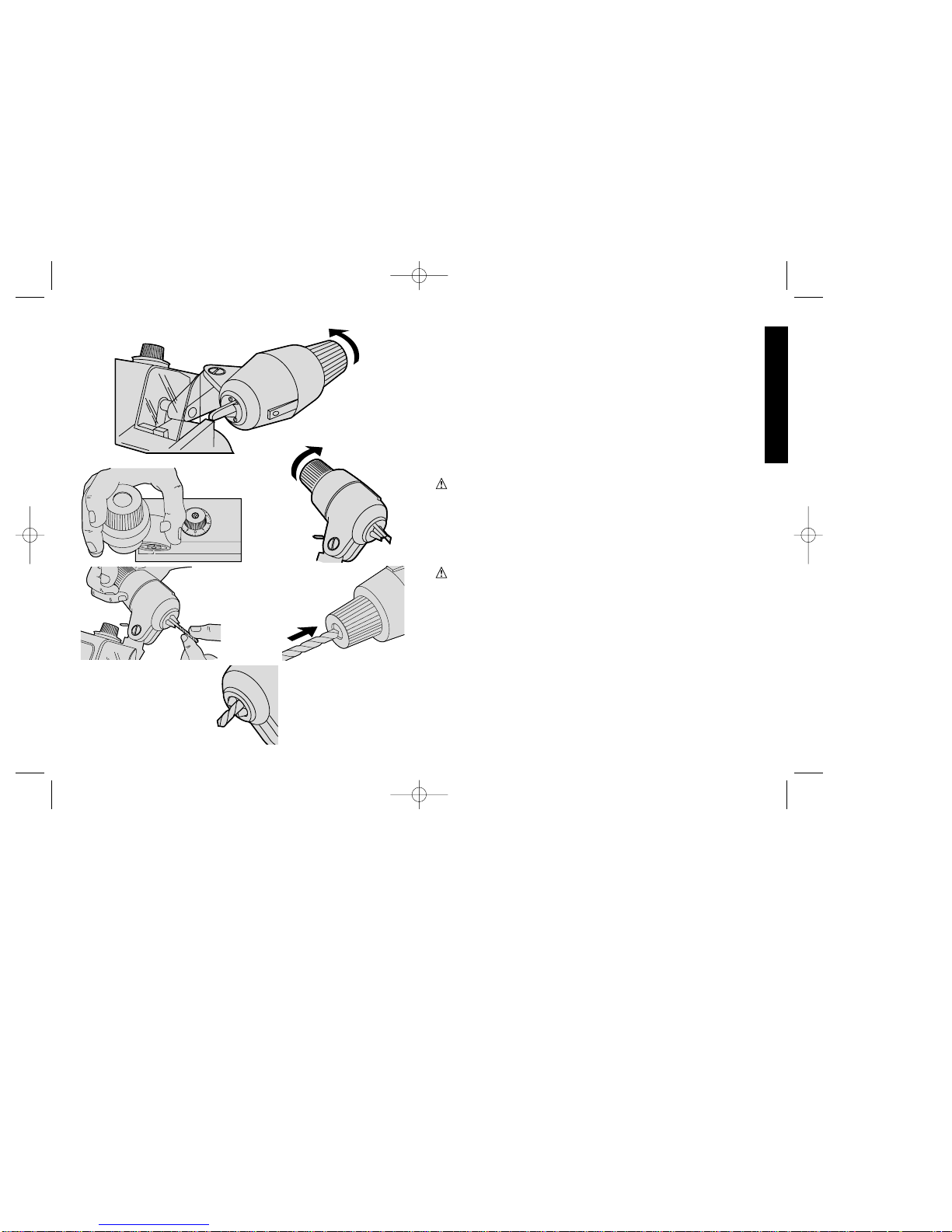
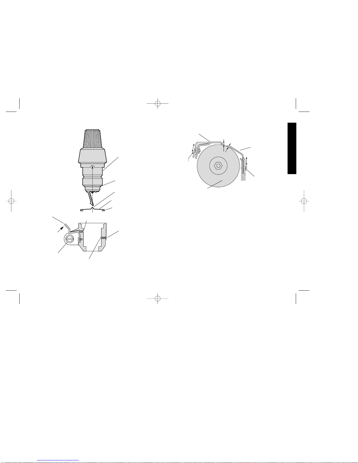
Sharpening of Drill Bits
(Figs. 11, 12, 13, 14, 15, 16)
PREPARING TO SHARPEN
NOTE: First, check the unit for the adjustments explained in the
“Adjustments” section of this manual.
1
. The swinghead has two indexing positions, 180° apart. Rotate sleeve
to make sure it is seated, with locator in top position. Make sure selector
switch on top of the tool is in the “S” (sharpen) position (Fig. 11).
2. Press latch toward swinghead and move swinghead toward
loading position (Fig. 12).
3. Open chuck jaws by turning chuck nut counter-clockwise (Fig.13).
4. Insert smaller diameter bits past the locator directly into the chuck
(Fig. 14).
5. Insert larger diameter bits through the opening in the chuck head
(Fig. 15).
6. Position bit so that tip is approximately 1/16" (1.6 mm) below end
of locator. Be sure straight edge at end of locator is flat against
flute. This positioning of the bit with the locator is the key to
satisfactory sharpening (Fig. 16).
English
FIG. 6 FIG. 7
FIG. 9
D
S
H
A
R
P
E
N
I
N
G
I
N
S
T
R
U
C
T
I
O
N
S
L
O
A
D
G
R
I
N
D
T
O
1
/
3
2
"
FIG. 8
S
S
H
A
R
P
E
N
I
N
G
I
N
S
T
R
U
C
T
I
L
O
A
D
FIG. 10
PARTING LINE
MARK
DW751/385103 5/2/02 12:51 PM Page 4
Page 8
SHARPENING FIRST CUTTING LIP (Figs. 17, 18, 19)
NOTE: Broken bits are more easily sharpened if they are first
roughed into shape by hand on a bench grinder. This will eliminate
unnecessary wear on the grinding wheel.
1.
With motor “OFF,” lower swinghead to sharpening position (Fig. 17).
2. Turn feed knob clockwise until bit is almost touching the wheel
when swinghead is rocked back and forth (Fig. 18).
NOTE: Turning feed knob clockwise feeds bit into wheel; turning
counterclockwise backs bit away from wheel.
3. Turn motor “ON,” Gently rock swinghead back and forth as you
turn the feed knob clockwise. DO NOT USE HEAVY HAND
PRESSURE WHEN ROCKING THE SWINGHEAD.
IMPORTANT: Advancing the feed knob one number (e.g., 2 to
3) moves the bit 5 thousandths of an inch closer to the wheel. Each
calibration (mark) between numbers moves the bit 1 1/4 thousandths.
4. Moving the feed knob clockwise one calibration (mark) at a time,
continue to rock the swinghead across the wheel until the edge of
the bit is about 1/32” (.8 mm) from the end of the locator. BE
CAREFUL NOT TO GRIND LOCATOR.
IMPORTANT: Make a note of the final feed knob setting because
you’ll need it when you sharpen the second lip.
5. Now turn feed knob counterclockwise several turns to back bit
away from grinding wheel.
6. Move swinghead down and back to rest position illustrated. Rotate
sleeve 180° clockwise until it snaps into the second index position.
(The locator will now be on the underside of the chuck.)(Fig. 19)
SHARPENING SECOND CUTTING LIP
1. Repeat steps 3 and 4 under “Sharpening first cutting lip.”
2. STOP SHARPENING WHEN THE FEED KNOB REACHES THE
CALIBRATION YOU NOTED.
5
English
FIG. 11
FIG. 12
FIG. 14
FIG. 13
FIG. 15
FIG. 16
DW751/385103 5/2/02 12:51 PM Page 5
Page 9

6
For finest finish, turn feed knob one more calibration and grind
bit. Without touching feed knob, turn sleeve 180° clockwise (step
6 on page 5) and grind first lip until sparking stops.
3. Turn motor “OFF.” Raise swinghead to loading position and
remove bit.
CAUTION: Tip of bit may be hot.
Wheel Dressing (Figs. 20, 21, 22)
The special grinding wheel included with your DEWALT drill bit
sharpener is ready to sharpen your bits. When the sharpening
surface becomes worn and uneven, it’s time to dress the wheel.
Follow these steps:
IMPORTANT: See instructions for shifting from “S” (sharpen) to
“D” (dress) under “Shifting selector to sharpen bits or dress wheel.”
After you have taken the necessary steps, proceed to:
1. Press latch and move swinghead to loading position.
2. Take diamond dressing tool which is kept in the spring-clip in back
of the sharpener. Remove protective sleeve. Position the dust
shield as shown below. Position diamond dresser in chuck, with
diamond tip 1/16" (1.6 mm) beyond locator as illustrated. Tighten
chuck jaws by turning chuck nut clock-wise. Slide dust shield up
against face of chuck to prevent grit and dust from fouling chuck.
(Fig. 20 & 21)
3. Move swinghead downward until latch engages. Adjust feed knob
clockwise until diamond tip almost touches sharpening surface of
the grinding wheel.
4. With SLIGHT PRESSURE, push swinghead back and away from
eyeshield until it stops.
5. Turn motor “ON.” Maintain light pressure, away from the
eyeshield, on the swinghead. Move the diamond back and forth
across the wheel by turning the dress knob clockwise and
counterclockwise. Feed the diamond into the wheel by turning
English
FIG. 17
FIG. 18
FIG. 19
SLEEVE
TURN SLEEVE 180°
DW751/385103 5/2/02 12:51 PM Page 6
Page 10
the feed knob, clockwise, one calibration at a time. Smooth,
continuous motion completely across the face of the wheel will
provide a smoother finish. Stopping the diamond on the wheel
will score it. Removing wheel material during the outside-to-inside
motion of the diamond will assure a finer finish (Fig. 22).
6. Turn motor “OFF.” Back off feed knob (turn counterclockwise)
enough so that diamond clears sharpening surface of wheel.
Return swinghead to loading position. Remove diamond dresser
and dust shield.
TO CHANGE FROM “D” (DRESSING) TO “S”
(SHARPENING)(Fig. 23)
1. Line dress knob mark up with parting line of housing.
2. Move swinghead close to eyeshield.
3 . Shift mode selector to “S.” DO NOT FORCE. If selector will not
seat, check position of dress knob mark.
Wheel Replacement
Replace the grinding wheel when it has been worn down from the
original 5" (127 mm) to 4" (102 mm) diameter.
CAUTION: REPLACE A CRACKED WHEEL IMMEDIATELY!
For replacement, use only a D
EWALT 5" (127 mm) x 3/4" (19 mm)
wheel (DW7510). This wheel is designed specifically for this tool.
To replace the grinding wheel:
1. UNPLUG TOOL.
2. Remove 3 screws holding wheel cover and remove cover.
3. Hold wheel with a rag to keep it from turning and remove spindle
nut and clamp washer (LEFT HAND THREAD—TURN NUT
CLOCKWISE). Remove wheel.
4. Move guard band and finger guard to uppermost position (Fig.
27.).
7
English
SH
AR
P
EN
ING
IN
ST
RU
CT
IO
N
S
S
W
I
N
G
H
E
A
D
M
O
D
E
S
E
L
E
C
T
O
R
F
E
E
D
K
N
O
B
L
O
A
D
P
U
S
H
L
A
T
C
H
G
R
I
N
D
T
O
1
/
3
2
"
E
N
T
I
R
E
L
O
C
A
T
O
R
E
D
G
E
T
O
U
C
H
I
N
G
F
L
U
T
E
S
S
D
T
I
G
H
T
E
N
D
R
E
S
S
FIG. 20
FIG. 22
FIG. 23
FIG. 21
SWINGHEAD
SHARPEN/DRESS
SELECTOR
PARTING LINE
MARK
DRESS
KNOB
DIAMOND
DRESSER
DUST
SHIELD
DW751/385103 5/2/02 12:51 PM Page 7
Page 11
8
5. Attach new wheel (Fig. 24) (Note that the wheel is marked to show
which side faces out.) with clamp washer and spindle nut. Hold
wheel with a rag and tighten nut counterclockwise. Do not
overtighten.
6. Adjust guard band and finger guard to about 1/16" (1.6 mm) from
wheel (Fig. 27) and tighten adjusting screws.
7. Replace wheel cover.
8. For best results dress the new wheel with the diamond dresser.
Adjustments
FROM TIME TO TIME ADJUSTMENTS MAY BE NECESSAR Y DUE
TO WEAR OR SEVERE HANDLING OF THE UNIT DURING
SHIPMENT OR MOVEMENT FROM PLACE TO PLACE. SHOULD
ADJUSTMENTS BECOME NECESSARY, THE FOLLOWING
PROCEDURES SHOULD BE FOLLOWED CAREFULLY TO
INSURE PROPER AND SAFE OPERATION OF YOUR
SHARPENER.
UNPLUG TOOL BEFORE MAKING ANY ADJUSTMENTS.
1. Looseness in Pivot Rod Bearing System (Fig. 25.)
A. Set selector lever to “S” (Sharpen).
B. Position swinghead with locator approximately 1/8” (3 mm)
above wheel.
C. Loosen both front bearing gib screws until slight side play in
pivot is evident.
D. While rocking swinghead, adjust back bearing gib screw until
very slight pivoting resistance is felt. Back off screw 1/8 to 1/4
turn.
E. Adjust front bearing top and bottom gib screws evenly, while
rocking swinghead, until slight pivoting resistance is felt.
2. Latch Adjustment (Fig. 26)
A. Move swinghead to sharpening position.
English
FIG. 24
SPINDLE
NUT
CLAMP
WASHER
CHUCK
KNOB
SHARPEN/DRESS
SELECTOR
BACK
BEARING
GIB
SCREW
FRONT
BEARING
GIB
SCREW
(TOP)
FRONT BEARING GIB
SCREW (BOTTOM)
PIVOT ROD
CHUCK
RETAINING
SCREW
SWING-
HEAD
FIG. 25
FEED KNOB
RETAINING SCREW
DW751/385103 5/2/02 12:51 PM Page 8
Page 12
B. Loosen chuck retaining set screw with 1/8" (3 mm) allen wrench
until chuck and detent spring can be removed from swinghead.
C. Adjust latch set screw with 1/16" (1.6 mm) allen wrench so that
swinghead locks firmly into sharpening position.
D. Replace detent spring (note orientation of “U” and “V” shaped
projections) and chuck.
E. Tighten set screw so that chuck is snug in swinghead but can
be easily rotated.
3. Finger Guard and Guard Band (Fig. 27)
Adjust opening between guards and wheel to 1/16" (1.6 mm) by
means of adjusting screws as shown. Maintain clearance as wheel
wears.
NOTE: This sharpener is completely adjusted at the factory.
However, due to rough handling that might occur during shipment,
slight readjustments may be necessary. Please take a few minutes to
check the adjustments of your unit.
9
English
FIG. 26
CHUCK
FELT SEAL
“V” SHAPE UP
DETENT SPRING
“U” SHAPE DOWN
CHUCK
RETAINING
SET SCREW
PLUG
LATCH SET SCREW
SWINGHEAD
CLAMP SCREW
PRESS
FIG. 27
GUARD
BAND
ADJUSTING
SCREW
GRINDING
WHEEL
FINGER GUARD
ADJUSTING
SCREW
FINGER
GUARD
GUARD
BAND
LATCH
1/16”
(1.6 MM)
1/16”
(1.6 MM)
DW751/385103 5/2/02 12:51 PM Page 9
Page 13
10
PROBLEM
1. Chisel angle too great—
greater than 135°
2. Chisel angle too small—
less than 120°
3. Bit will not drill
4. Discoloration (burning)
near cutting lips
5. Flats or chatter marks
on ground surfaces
6. Large variation in lip height
(point off center)
7. Swinghead will not stay
locked in sharpening or
dressing position
8. Hard to pivot swinghead
back and forth
9. Bent locator
10.Unit getting unusually hot
English
Troubleshooting
REMEDY
Bit was not ground close enough to
locator or was positioned incorrectly, See
Step 6 under “Preparing to sharpen.”
Edge of locator was not flat against flute.
See step 6 under “Preparing to sharpen.”
Or bit was ground too close to locator.
Insufficient relief angle. See Step 6
under “Preparing to sharpen,” for proper
positioning of bit.
Material is being removed too fast. Slow
down feed rate.
A. Looseness in pivot rod bearing
system—see adjustments
B. Wheel needs dressing
C. Feed at slower rate
D. Slow down speed of rocking motion
A. Bent bit
B. Looseness in pivot rod bearings—
follow adjustments
C. Unequal hand pressure on
swinghead while sharpening
Latch set screw needs adjustment.
Gib screws adjusted too tight.
Place a 1/8" (3 mm) bit in chuck and
bend locator until the tip is directly over
bit center or replace locator.
Check motor air intake and exhaust
openings on bottom of tool for blockage.
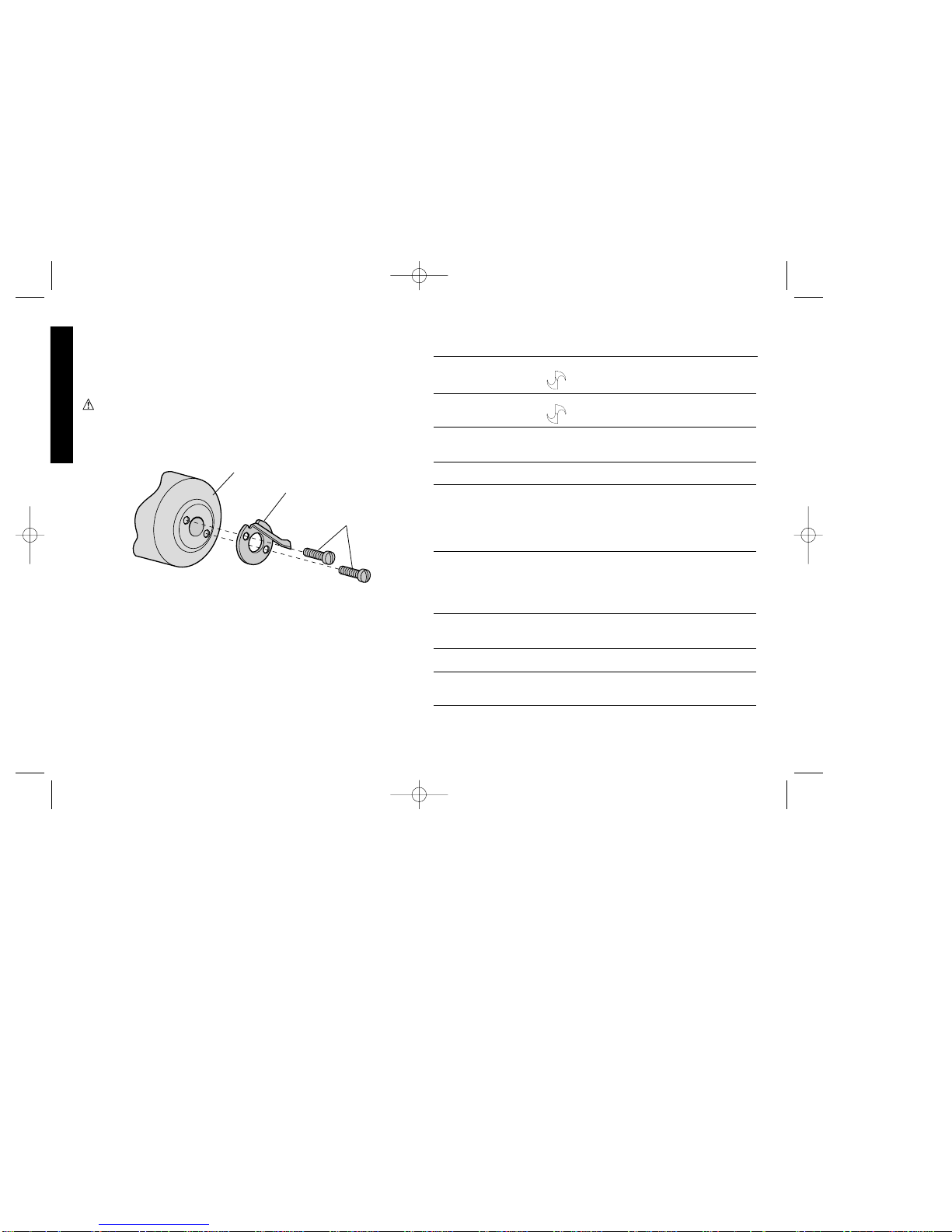
4. The Locator (Fig. 28)
The locator on the chuck of your drill bit sharpener has been
inspected at the factory for proper positioning and assembly. Should
the locator edge become damaged for any reason while grinding
during the initial learning operation of the tool, it is easily replaced
with the extra locator provided.
CAUTION: Tighten screws just enough to seat locator against
chuck. DO NOT OVERTIGHTEN
FIG. 28
CHUCK
LOCATOR
SCREWS
DW751/385103 5/2/02 12:51 PM Page 10
Page 14

damage caused where repairs have been made or attempted by
others. This warranty gives you specific legal rights and you may
have other rights which vary in certain states or provinces.
In addition to the warranty, D
EWALT tools are covered by our:
30 DAY NO RISK SATISFACTION GUARANTEE
If you are not completely satisfied with the performance of your
D
EWALTheavy duty industrial tool, simply return it to the participating
seller within 30 days for a full refund. Please return the complete unit,
transportation prepaid. Proof of purchase may be required.
11
English
Maintenance
Self lubricating bearings are used in the tool and periodic
relubrication is not required. However, it is recommended that, once
a year, you take or send the tool to a D
EWALT Service Center for
thorough cleaning and inspection.
STANDARD EQUIPMENT
1. Special grinding wheel with 3° bevel on sharpening surface.
2. Diamond wheel dresser.
3. Extra locator.
Accessories
Recommended accessories for use with your tool are available at
extra cost from your distributor or authorized service center.
• Replacement 5" (127 mm) x 3/4" (19 mm) Grinding Wheel
(DW7510)
• Replacement Diamond Dresser (DW 7511).
• Bit Locator (DW 7512).
CAUTION: The use of any non-recommended accessory may be
hazardous.
Important
To assure product SAFETY and RELIABILITY, repairs, maintenance
and adjustment (including brush inspection and replacement) should
be performed by authorized service centers or other qualified service
organizations, always using identical replacement parts.
Full Warranty
DEWALT heavy duty industrial tools are warranted for one year from
date of purchase. We will repair, without charge, any defects due to
faulty materials or workmanship. For warranty repair information,
call 1-800-4-D
EWAL T. This warranty does not apply to accessories or
See ‘Tools-Electric’
– Yellow Pages –
for Service & Sales
DW751/385103 5/2/02 12:51 PM Page 11
Page 15

12
Importantes mesures de sécurité
AVERTISSEMENT : Afin de réduire les risques d’incendie, de
secousses électriques ou de blessures lorsqu’on utilise des outils
électriques, il faut toujours respecter les mesures de sécurité
suivantes.
LIRE TOUTES LES DIRECTIVES.
Mise à la terre
L’outil devrait être mis à la terre lors de son utilisation afin de protéger
l’utilisateur contre les risques de secousses électriques. L’outil est
doté d’un cordon trifilaire et d’une fiche à trois broches de type mis à
la terre qui s’insère dans une prise mise à la terre. Le conducteur
vert (ou vert et jaune) du cordon est le fil de mise à la terre. Ne
jamais raccorder le fil vert (ou vert et jaune) à une borne sous
tension. Lorsque l’outil est conçu pour recevoir une alimentation de
moins de 150 volts, il est doté d’une fiche semblable à celle illustrée
à la figure A. Lorsque l’outil est conçu pour recevoir une alimentation
variant entre 150 et 250 volts, il est doté d’une fiche semblable à celle
illustrée à la figure D. On peut se procurer un adaptateur (fig. B et
C) pour brancher une fiche semblable à celle de la figure A dans
des prises à deux orifices. Il faut alors relier la tige, la cosse ou le
dispositif similaire de couleur verte à une mise à la terre permanente
(comme une prise bien mise à la terre). Il n’y a pas d’adaptateur pour
Français
S
H
A
R
P
E
N
IN
G
I
N
S
T
R
U
C
T
I
O
N
S
S
W
IN
G
H
E
A
D
M
O
D
E
S
E
L
E
C
T
O
R
F
E
E
D
K
N
O
B
L
O
A
D
P
U
S
H
L
A
T
C
H
G
R
I
N
D
T
O
1
/3
2
"
ENTIRE
LOCATOR EDGE
TOUCHING
FLUTE
SÉLECTEUR -
AFFÛTE-FORET OU
DÉCRASSE-MEULE
BOUTON
D’ALIMENTATION
TÊTE PIVOTANTE
MANCHON-REVOLVER
MANDRIN
POSITIONNEUR
MEULE
LOQUET
ÉCRAN
PROTECTEUR
COUVERCLE
DE LA MEULE
BOUTON
DU DÉCRASSE-
MEULE
ÉCRAN
ANTIPOUSSIÈRE
DÉCRASSE-
MEULE DIAMANT
VIS DE RÉGLAGE
DE LA BANDE
DE PROTECTION
INTERRUPTEUR
DU MOTEUR
AB CD
BROCHE DE PRISE
MISE À LA TERRE
BROCHE DE MISE À
LA TERRE
PRISE MISE
À LA TERRE
DISPOSITIF DE
MISE À LA TERRE
ADAPTATEUR
POUR TOUT RENSEIGNEMENT SUPPLÉMENTAIRE SUR CET
OUTIL OU TOUT AUTRE OUTIL D
EWALT, COMPOSER SANS
FRAIS LE NUMÉRO :
1 800 4-DEWALT (1 800 433-9258).
DW751/385103 5/2/02 12:51 PM Page 12
Page 16

la fiche illustrée à la figure D. L’ADAPTATEUR ILLUSTRÉ AUX
FIGURES B ET C NE PEUT PAS ETRE UTILISÉ AU CANADA.
Mesures de sécurité pour tous les outils
• BIEN DÉGAGER LA SURFACE DE TRAVAIL. Des surfaces et
des établis encombrés peuvent être la cause de blessures.
• TENIR COMPTE DU MILIEU DE TRAVAIL. Protéger les outils
électriques de la pluie. Ne pas s’en servir dans des endroits
humides ou mouillés. Bien éclairer la surface de travail. Ne pas se
servir de l’outil en présence de liquides ou de vapeurs
inflammables.
• SE PROTÉGER CONTRE LES SECOUSSES ÉLECTRIQUES.
Éviter tout contact avec des objets mis à la terre, comme des
tuyaux, radiateurs, cuisinières, réfrigérateurs et autres objets du
genre.
• ÉLOIGNER LES ENFANTS. Tous les visiteurs doivent être tenus
à l’écart de l’aire de travail et il faut les empêcher de toucher à
l’outil ou au cordon de rallonge.
• RANGER LES OUTILS INUTILISÉS. Il faut ranger les outils dans
un endroit sec, situé en hauteur ou fermé à clé, hors de la portée
des enfants.
• NE JAMAIS FORCER L’OUTIL. Afin d’obtenir un rendement sûr
et efficace, utiliser l’outil à son rendement nominal.
• UTILISER L’OUTIL APPROPRIÉ. Ne jamais exiger d’un petit outil
ou d’un accessoire le rendement d’un outil de fabrication plus
robuste. Se servir de l’outil selon l’usage prévu.
• PORTER DES VÊTEMENTS APPROPRIÉS. Éviter de porter des
vêtements amples et des bijoux qui peuvent être happés par les
pièces en mouvement. Porter des gants de caoutchouc et des
chaussures à semelle antidérapante pour travailler à l’extérieur.
Protéger la chevelure si elle est longue.
• PORTER DES LUNETTES DE SÉCURITÉ. Porter également un
masque respiratoire si le travail de coupe produit de la poussière.
• NE PAS MANIPULER LE CORDON DE FAÇON ABUSIVE. Ne
pas transporter l’outil par le cordon ni tirer sur ce dernier pour le
débrancher de la prise. Éloigner le cordon des sources de chaleur,
des flaques d’huile et des arêtes tranchantes.
• ASSUJETTIR LA PIÈCE. Immobiliser la pièce à l’aide de brides
ou d’un étau. On peut alors se servir des deux mains pour faire
fonctionner l’outil, ce qui est plus sûr.
• NE PAS DÉPASSER SA PORTÉE. Toujours demeurer dans une
position stable et garder son équilibre.
• PRENDRE SOIN DES OUTILS. Conserver les outils propres et
affûtés pour qu’ils donnent un rendement supérieur et sûr. Suivre
les directives concernant la lubrification et le remplacement des
accessoires. Inspecter régulièrement le cordon de l’outil et le faire
réparer au besoin à un atelier d’entretien autorisé. Inspecter
régulièrement les cordons de rallonge et les remplacer lorsqu’ils
sont endommagés. S’assurer que les poignées sont toujours
propres, sèches et libres de toute tache d’huile ou de graisse.
• DÉBRANCHER OU VERROUILLER EN POSITION HORS
TENSION LES OUTILS NON UTILISÉS. Respecter cette mesure
lorsqu’on ne se sert pas de l’outil, ou qu’on doit le réparer ou en
changer un accessoire (comme une lame, un foret ou un couteau).
• ENLEVER LES CLÉS DE RÉGLAGE. Prendre l’habitude de
vérifier si les clés de réglage ont été retirées avant de faire
démarrer l’outil.
• ÉVITER LES DÉMARRAGES ACCIDENTELS. Ne pas laisser le
doigt sur l’interrupteur lorsqu’on transporte l’outil. S’assurer que
l’interrupteur est à la position hors circuit lorsqu’on branche l’outil.
• CORDONS DE RALLONGE. Utiliser seulement des cordons de
rallonge trifilaires ayant une fiche à 3 broches ainsi qu’une prise à
3 trous acceptant la fiche de l’outil. Remplacer ou réparer les
cordons de rallonge endommagés. S’assurer que le cordon de
rallonge est en bon état. Lorsqu’on se sert d’un cordon de
rallonge, s’assurer qu’il est de calibre approprié pour la tension
nécessaire au fonctionnement de l’outil. L’utilisation d’un cordon
13
Français
DW751/385103 5/2/02 12:51 PM Page 13
Page 17

14
de calibre inférieur occasionne une baisse de tension entraînant
une perte de puissance et la surchauffe. Le tableau suivant
indique le calibre approprié selon la longueur du cordon et les
mentions de la plaque signalétique de l’outil. En cas de doute,
utiliser un cordon de calibre supérieur. Le chiffre indiquant le
calibre est inversement proportionnel au calibre du cordon.
• CORDONS DE RALLONGE PRÉVUS POUR L’EXTÉRIEUR.
Lorsque l’outil est utilisé à l’extérieur, ne se servir que d’un cordon
de rallonge conçu pour l’extérieur et portant la mention appropriée.
• DEMEURER VIGILANT. Travailler avec vigilance et faire preuve
de bon sens. Ne pas se servir de l’outil lorsqu’on est fatigué.
• VÉRIFIER LES PIÈCES ENDOMMAGÉES. Avant de continuer à
utiliser l’outil, il faut vérifier si le protecteur ou toute autre pièce
endommagée remplit bien la fonction pour laquelle il a été prévu.
Vérifier l’alignement et les attaches des pièces mobiles, le degré
d’usure des pièces et leur montage, ainsi que tout autre facteur
susceptible de nuire au bon fonctionnement de l’outil. Faire
réparer ou remplacer tout protecteur ou toute autre pièce
endommagée dans un centre de service autorisé, sauf si le
présent guide fait mention d’un avis contraire. Confier le
remplacement de tout interrupteur défectueux à un centre de
service autorisé. Ne jamais se servir d’un outil dont l’interrupteur
est défectueux.
Mesures de sécurité additionnelles
relatives aux affûte-forets
AVERTISSEMENT: Cet outil professionnel est conçu pour affûter
rapidement et précisément des forets hélicoïdaux à 2 goujures et
à filet à droite de 3 mm (1/8 po) à 13 mm (1/2 po) de diamètre. NE
PAS tenter d’affûter des forets au carbure ou au cobalt. Puisqu ’il faut
respecter les consignes afin d’obtenir des résultats satisfaisants, lire
attentivement les directives relatives au fonctionnement et, par un
surcroît de protection, accorder une attention particulière aux
mesures de sécurité.
• Porter des lunettes de sécurité.
• Utiliser la meule appropriée au régime de l’outil.
• Remplacer immédiatement une meule craquée. Manipuler les
meules avec soin en évitant de les frapper ou de les échapper. NE
PAS se servir d’une meule qui est tombée. Avant de s’en servir,
vérifier chaque meule afin de s’assurer qu’elle ne comporte aucun
craque ni défaut. Le cas échéant, jeter la meule.
• Toujours utiliser des protecteurs et des écrans protecteurs.
S’assurer que les écrans protecteurs sont bien installés.
• Éviter de trop serrer l’écrou de la meule. Avant d’installer une
nouvelle meule, s’assurer que la vitesse nominale de la meule est
égale ou supérieure à la vitesse sous vide indiquée sur la plaque
signalétique de l’outil.
• Utiliser seulement les brides fournies avec l’outil.
• Boulonner l’affûte-foret à un établi afin d’en empêcher le
déplacement.
• Régler la distance entre la meule et les protecteurs de sorte qu’il y
ait un jeu maximal de 1,6 mm (1/16 po) puisque le diamètre de la
meule décroît à l’usage.
• Utiliser les accessoires seulement de manière appropriée.
CONSERVER CES MESURES.
Français
Calibre minimal des cordons de rallonge
Tension Longueur totale du cordon en pieds
120 V De 0 à 25 De 26 à 50 De 51 à 100 De 101 à 150
240 V De 0 à 50 De 51à 100 De 101 à 200 De 201 à 300
Intensité (A)
Au Au Calibre moyen de fil (AWG)
moins plus
0-6 18 16 16 14
6 - 10 18 16 14 12
10 - 12 16 16 14 12
12 - 16 14 12 Non recommandé
DW751/385103 5/2/02 12:51 PM Page 14
Page 18

Précisions sur les forets
Une exigence primordiale pour l’obtention de trous percés avec
précision consiste à ce qu’il y ait une différence minimale entre les
hauteurs des arêtes de coupe des deux goujures. Une variation
entre les hauteurs des arêtes de coupe nuit au centrage du point qui
procure le perçage excentrique (fig. 1, 2 et 3). Consulter le
paragraphe 6 du guide de dépannage du présent guide. L’affûte-
foret D
EWALT est conçu pour procurer des hauteurs d’arêtes de
coupe égales et un point central.
Montage de l’affûte-foret
AFIN D’OPTIMISER LES RÉSULTATS, INSTALLER L’AFFÛTEFORET SUR UNE SURFACE DE TRAVAIL SOLIDE. Percer deux
trous de 8 mm (5/16 po) dans l’établi (fig. 4). Y insérer deux boulons
à tête bombée de 6 mm (1/4 po) de diamètre. Faire glisser les têtes
des boulons dans les trous qui se trouvent sur la face inférieure de
l’affûte-foret (fig. 5). Serrer les écrous sur les boulons uniformément
en exerçant une force modérée. Éviter de trop serrer!
Principales composantes
de l’affûte-foret
MISE EN GARDE :
• Prendre garde - connaître et respecter toutes les MESURES DE
SÉCURITÉ.
• S’assurer que le positionneur est loin de la meule avant de
démarrer l’outil.
• Exercer une pression légère et imprimer un mouvement uniforme
lorsqu’on balance la tête pivotante pour l’affûtage.
• Lorsqu’on passe du mode d’AFFÛTE-FORET à celui de DÉCRASSE-
MEULE, et vice versa, respecter les consignes avec soin.
• Remplacer immédiatement une meule craquée.
• Ne jamais démonter l’outil ni en refaire le filage du système
électrique.
15
Français
FIG. 4
FIG. 1
FIG. 2
(122,2 mm)
Contour de l'outil
Devant
42,5 mm
3 1/4 po
4 13/16 po
FIG. 5
ANGLE
D’HÉLICE
FIG. 3
ANGLE DE L’ARÊTE
CENTRALE DE 120°
À 135°
ANGLE DE LA POINTE
COMPRIS 118°
ANGLE
DE DÉPOUILLE
GOUJURE
LONGUEUR TAILLÉE
ÂME
ARÊTE
DE COUPE
FRONTALE
DW751/385103 5/2/02 12:51 PM Page 15
Page 19

16
Le sélecteur du mode de fonctionnement programme l’outil pour
affûter les forets ou pour décrasser les meules. Le bouton
d’alimentation procure la précision du taux d’alimentation
(enlèvement du matériau) lors de l’affûtage. Le manchon-revolver
permet d’affûter d’abord un côté d’un foret, puis l’autre sans retirer
le foret du mandrin. La tête pivotante permet de déplacer le foret le
long de la meule continuellement à l’angle approprié. Le mandrin
retient le foret en place pendant l’affûtage. Le positionneur guide
l’emplacement du foret de façon à assurer un affûtage correct et
précis.
Sélecteur pour l’affûte-foret
ou le décrasse-meule
(Fig. 6, 7, 8, 9 et 10)
Pour affûter un foret, le sélecteur doit se trouver à la position “S”
(pour affûter). La position “D” (pour décrasser) sert pour décrasser
les meules.
IMPORTANT : Lorsque le changement de mode de
fonctionnement est mal fait, cela présente des risques de
dommage à l’outil, et cela peut même le rendre inopérant. Les
méthodes de changement appropriées sont illustrées.
PASSAGE DU MODE “S” (AFFÛTE-FORET) AU MODE “D”
(DÉCRASSE-MEULE)
NOTE : Exécuter l’étape1 avant de passer à l’étape 2. Sinon, la tête
pivotante ne se déplace pas vers le haut jusqu’à l’écran protecteur.
1. Faire tourner la tête en position d’affûtage normale (fig. 6).
2. Faire tourner la tête jusqu’à ce qu’elle touche à l’écran protecteur
(fig. 7).
3. Déplacer le sélecteur à la position “D” (fig. 8).
PASSAGE DU MODE “D” (DÉCRASSE-MEULE) AU MODE “S”
(AFFÛTE-FORET)
Français
FIG. 6 FIG. 7
FIG. 9
D
S
H
A
R
P
E
N
I
N
G
I
N
S
T
R
U
C
T
I
O
N
S
L
O
A
D
G
R
I
N
D
T
O
1
/
3
2
"
FIG. 8
S
S
H
A
R
P
E
N
I
N
G
I
N
S
T
R
U
C
T
I
L
O
A
D
FIG. 10
PLAN DE JOINT
DU MOULE
MARQUE
DW751/385103 5/2/02 12:51 PM Page 16
Page 20

1. Aligner la marque du bouton du décrasse-meule sur le plan de
joint du moule. Placer la tête pivotante près de l’écran protecteur
(fig. 9).
2. Déplacer le sélecteur à la position “S”. NE PAS FORCER.
Lorsque le sélecteur ne s’enfonce pas en place, faire basculer le
bouton du décrasse-meule de l’avant vers l’arrière tout en
exerçant une légère pression sur le sélecteur jusqu’à ce qu’il
s’enclenche en place (fig. 10).
Affûtage de forets
(Fig. 11, 12, 13, 14, 15 et 16)
PRÉPARATIFS EN VUE DE L’AFFÛTAGE
NOTE : D’abord, il faut vérifier les réglages de l’outil mentionnés à
la rubrique “Réglage” du présent guide.
1. La tête pivotante comporte deux positions, à 180° l’une de l’autre.
Faire tourner le manchon pour s’assurer qu’il est bien enclenché, avec
le positionneur dans l’emplacement supérieur. S’assurer que le
sélecteur du dessus de l’outil se trouve à la position “S” (affûtage)
(fig. 11).
2. Enfoncer le loquet vers la tête pivotante et déplacer la tête vers
la position de chargement (fig. 12).
3. Ouvrir les mâchoires du mandrin en faisant tourner l’écrou du
mandrin dans le sens antihoraire (fig. 13).
4. Insérer les forets de petits diamètres au-delà du positionneur,
directement dans le mandrin (fig. 14).
5. Insérer les forets de grands diamètres dans l’ouverture du
mandrin (fig. 15).
6. Placer le foret de sorte que la pointe se trouve à environ 1,6 mm
(1/16 po) sous l’extrémité du positionneur. S’assurer que le
rebord droit à l’extrémité du positionneur repose à plat contre la
goujure. On obtient des résultats satisfaisants lorsqu’on place
bien le foret dans le positionneur (fig. 16).
17
Français
FIG. 11
FIG. 12
FIG. 14
FIG. 13
FIG. 15
FIG. 16
DW751/385103 5/2/02 12:51 PM Page 17
Page 21

18
AFFÛTAGE DE LA PREMIÈRE ARÊTE DE COUPE
FRONTALE (FIG. 17, 18 ET 19)
NOTE : Il est plus aisé d’affûter un foret brisé lorsqu’on le façonne
d’abord à la main à l’aide d’une meuleuse d’établi. On élimine de la
sorte l’usure inutile de la meule.
1. Lorsque le moteur se trouve en position d’arrêt (OFF), abaisser
la tête pivotante à la position d’affûtage (fig. 17).
2. Faire tourner le bouton d’alimentation dans le sens horaire jusqu’à
ce que le foret touche presque à la meule lorsqu’on bascule la tête
de l’avant vers l’arrière (fig. 18).
NOTE : Lorsqu’on fait tourner le bouton d’alimentation dans le sens
horaire, le foret avance sur la meule; dans le sens antihoraire, on
éloigne le foret de la meule.
3. Pour mettre le moteur en marche (ON), faire basculer doucement la
tête pivotante tout en faisant tourner le bouton d’alimentation dans le
sens horaire. NE PAS EXERCER UNE FORTE PRESSION
MANUELLE SUR LA TÊTE LORSQU’ON LA FAIT BASCULER.
IMPORTANT : Lorsqu’on avance le bouton d’alimentation d’un
cran (de 2 à 3, par exemple), le foret se déplace de 5 millièmes de
pouce vers la meule. Chaque degré (marque) entre les chiffres
correspond à un déplacement de 1 1/4 millième du foret
4. Tout en déplaçant le bouton d’alimentation d’un cran (marque) à
la fois, continuer de faire basculer la tête pivotante le long de la
meule jusqu’à ce que l’arête du foret se trouve à environ 0,8 mm
(1/32 po) de l’extrémité du positionneur. PRENDRE GARDE DE
NE PAS AFFÛTER LE POSITIONNEUR.
IMPORTANT : Prendre note du dernier réglage du bouton
d’alimentation car on en a besoin pour affûter la deuxième arête.
5. Puis faire tourner le bouton d’alimentation dans le sens antihoraire
de plusieurs tours afin d’éloigner le foret de la meule.
6. Abaisser la tête pivotante vers l’arrière en position de repos
illustrée. Faire tourner le manchon sur 180° dans le sens horaire
jusqu’à ce qu’il s’enclenche dans la deuxième position. (Le
positionneur se trouve alors sous le mandrin (fig. 19).)
Français
FIG. 17
FIG. 18
FIG. 19
MANCHON
FAIRE TOURNER LE MANCHON SUR 180°.
DW751/385103 5/2/02 12:51 PM Page 18
Page 22

AFFÛTAGE DE LA DEUXIÈME ARÊTE DE COUPE FRONTALE
1. Répéter les étapes 3 et 4 de la rubrique “Affûtage de la première
arête de coupe frontale”.
2. CESSER D’AFFÛTER LORSQUE LE BOUTON
D’ALIMENTATION ATTEINT LE DEGRÉ NOTÉ
PRÉCÉDEMMENT.
Afin d’obtenir un fini satiné, faire tourner le bouton d’alimentation
d’un autre degré et affûter le foret. Sans toucher au bouton
d’alimentation, faire tourner le manchon sur 180° dans le sens
horaire (étape 6 à la page 18) et affûter la première arête jusqu’à
ce qu’il n’y ait plus de production d’étincelles.
3. Arrêter le moteur (OFF). Soulever la tête pivotante à la position
de chargement et retirer le foret.
MISE EN GARDE : Le bout du foret peut être brûlant.
Décrasse-meule (Fig. 20, 21 et 22)
La meule spéciale fournie avec l’affûte-foret DEWALT est prête à
servir. Lorsque ses surfaces d’affûtage deviennent usées et
inégales, il faut décrasser la meule. Faire ce qui suit.
IMPORTANT: Voir les directives pour passer du mode“S” (affûte-
foret) au mode “D” (décrasse-meule) sous la rubrique relative au
sélecteur. Après avoir respecté les consignes appropriées, faire ce
qui suit.
1. Enfoncer le loquet et déplacer la tête à la position de chargement.
2. Prendre le décrasse-meule diamant qui se trouve dans une pince
à ressort à l’arrière de l’affûte-foret. En retirer le manchon
protecteur. Placer l’écran antipoussière de la façon illustrée plus
bas. Placer le décrasse-meule diamant dans le mandrin en
plaçant la pointe diamant à 1,6 mm (1/16 po) au-dessus du
positionneur comme le montre la figure. Serrer les mâchoires du
mandrin en faisant tourner l’écrou du mandrin dans le sens
horaire. Faire glisser l’écran antipoussière vers le haut contre la
19
Français
S
H
A
RP
E
N
IN
G
IN
S
TR
U
C
TION
S
S
W
I
N
G
H
E
A
D
M
O
D
E
S
E
L
E
C
T
O
R
F
E
E
D
K
N
O
B
L
O
A
D
P
U
S
H
L
A
T
C
H
G
R
I
N
D
T
O
1
/
3
2
"
E
N
T
I
R
E
L
O
C
A
T
O
R
E
D
G
E
T
O
U
C
H
I
N
G
F
L
U
T
E
S
S
D
T
I
G
H
T
E
N
D
R
E
S
S
FIG. 22
FIG. 23
TÊTE
PIVOTANTE
SÉLECTEUR - AFFÛTE-FORET
OU DÉCRASSE-MEULE
PLAN DE JOINT
DU MOULE
MARQUE
BOUTON
DU DÉCRASSE-
MEULE
MEULE
DIAMANT
ÉCRAN
ANTIPOUSSIÈRE
DW751/385103 5/2/02 12:51 PM Page 19
Page 23

20
face du mandrin afin d’empêcher les saletés et la poussière
d’encrasser le mandrin (fig. 20 et 21).
3. Déplacer la tête pivotante vers le bas jusqu’à ce que le loquet
s’enclenche. Régler le bouton d’alimentation dans le sens horaire
jusqu’à ce que la pointe diamant touche presque la surface
d’affûtage de la meule.
4. En exerçant une LÉGÈRE PRESSION, pousser la tête pivotante
vers l’arrière et loin de l’écran protecteur jusqu’à ce qu’elle
s’arrête.
5. Faire démarrer le moteur. Exercer une légère pression, en
éloignant la tête de l’écran protecteur. Déplacer le diamant vers
l’avant et l’arrière sur la meule en faisant tourner le bouton du
décrasse-meule dans les sens horaire et antihoraire. Faire
avancer le diamant sur la meule en faisant tourner le bouton
d’alimentation, dans le sens horaire, d’un cran à la fois. On
obtient un fini satiné en imprimant un mouvement uniforme et
continu sur toute la face de la meule. On risque de marquer la
meule en y arrêtant le diamant. Le fini sera encore plus satiné si
on enlève le matériau de la meule lors du mouvement extérieurintérieur du diamant (fig. 22).
6. Arrêter le moteur. Éloigner le bouton d’alimentation (dans le sens
antihoraire) suffisamment pour éloigner le diamant de la surface
d’affûtage de la meule. Remettre la tête pivotante en position de
chargement. Enlever le décrasse-meule diamant et l’écran
antipoussière.
PASSAGE DU MODE “D” (DÉCRASSE-MEULE) AU MODE “S”
(AFFÛTE-FORET)(FIG. 23)
1. Aligner le bouton du décrasse-meule sur le plan de joint du moule.
2. Déplacer la tête pivotante près de l’écran protecteur.
3. Déplacer le sélecteur à la position “S”. NE PAS FORCER.
Lorsque le sélecteur ne s’enfonce pas en place, vérifier la position
de la marque du bouton du décrasse-meule.
Remplacement de la meule
Il faut remplacer la meule lorsqu’elle passe de son diamètre original
de 127 mm (5 po) à un diamètre de 102 mm (4 po).
MISE EN GARDE : REMPLACER IMMÉDIATEMENT UNE
MEULE CRAQUÉE!
Utiliser seulement une meule de rechange D
EWALT de 127 mm
(5 po) sur 19 mm (3/4 po) (modèle DW7510). Cette meule a été
spécialement conçue pour l’outil.
Faire ce qui suit pour remplacer la meule.
1. DÉBRANCHER L’OUTIL.
2. Retirer les trois vis retenant le couvercle de la meule et enlever ce
dernier.
3. Retenir la meule à l’aide d’un chiffon afin de l’empêcher de bouger
et retirer l’écrou de l’arbre ainsi que la rondelle de serrage (FILET
À GAUCHE - FAIRE TOURNER L’ÉCROU DANS LE SENS
HORAIRE). Enlever la meule.
4. Déplacer la bande de protection et le protège-doigts dans la
position supérieure (fig. 27).
5. Fixer la nouvelle meule (fig. 24) (prendre note que la meule porte
une mention indiquant quelle face va vers l’extérieur) à l’aide de la
rondelle de serrage et de l’écrou de l’arbre. Retenir la meule à
l’aide d’un chiffon et serrer l’écrou dans le sens antihoraire. Éviter
de trop serrer.
6. Régler la bande de protection et le protège-doigts à environ
1,6 mm (1/16 po) de la meule (fig. 27) et serrer les vis de réglage.
7. Remettre le couvercle de la meule en place.
8. Afin d’optimiser les résultats, se servir du décrasse-meule
diamant pour décrasser la nouvelle meule.
Réglages
DE TEMPS À AUTRE, IL FAUT RÉGLER L’OUTIL EN RAISON DE
L’USURE OU DU MAUVAIS TRAITEMENT INFLIGÉ À L’OUTIL
Français
DW751/385103 5/2/02 12:51 PM Page 20
Page 24

PENDANT LE TRANSPORT OU LE DÉPLACEMENT D’UN
ENDROIT À UN AUTRE. LE CAS ÉCHÉANT, FAIRE CE QUI SUIT
AVEC SOIN AFIN DE S’ASSURER DU FONCTIONNEMENT SÛR
ET APPROPRIÉ DE L’OUTIL.
DÉBRANCHER L’OUTIL AVANT DE LE RÉGLER.
1. Jeu dans le système de support de la tige de rotation (fig. 25)
A. Régler le levier du sélecteur à la position “S” (affûter).
B. Placer la tête pivotante avec le positionneur à environ 3 mm
(1/8 po) au-dessus de la meule.
C. Desserrer les deux vis à talon du roulement avant jusqu’à ce
qu’on obtienne un très léger jeu latéral de la tige.
D. Tout en basculant la tête pivotante, régler la vis à talon du
roulement arrière jusqu’à ce qu’on obtienne une très légère
résistance à la rotation. Reculer la vis de 1/8 à 1/4 tour.
E. Régler uniformément les vis supérieure et inférieure du
roulement avant tout en basculant la tête pivotante, jusqu’à ce
qu’on ressente une légère résistance à la rotation.
2. Réglage du loquet (fig. 26)
A. Déplacer la tête pivotante à la position d’affûtage.
B. Desserrer la vis de pression du mandrin à l’aide d’une clé
hexagonale de 3 mm (1/8 po) jusqu’à ce que le mandrin et le
ressort de détente puissent être enlevés de la tête pivotante.
C. Régler la vis de pression du loquet avec une clé hexagonale de
1,6 mm (1/16 po) de sorte à verrouiller fermement la tête
pivotante en position d’affûtage.
D. Remettre le ressort de détente (remarquer le sens des formes
en “U” et en “V”) et le mandrin en place.
E. Serrer la vis de pression de sorte que le mandrin soit tout
contre la tête pivotante mais qu’on puisse facilement le faire
tourner.
3. Protège-doigts et bande de protection (fig. 27)
21
Français
FIG. 24
ÉCROU
DE L’ARBRE
RONDELLE
DE SERRAGE
BOUTON
DU MANDRIN
SÉLECTEUR AFFÛTE-FORET OU
DÉCRASSE-MEULE
VIS À TALON
DU ROULEMENT
ARRIÊRE
VIS À TALON
DU ROULEMENT
AVANT
(SUPÉRIEURE)
VIS À TALON DU ROULEMENT
AVANT (INFÉRIEURE)
TIGE DE ROTATION
VIS
DE RETENUE
DU MANDRIN
TÊTE
PIVOTANTE
FIG. 25
VIS DE RETENUE
DU BOUTON
D’ALIMENTATION
DW751/385103 5/2/02 12:51 PM Page 21
Page 25

22
Français
MANDRIN
RONDELLE
DE FEUTRE
FORME EN “V”
VERS LE HAUT
RESSORT
DE DÉTENTE
FORME EN “U”
VERS LE BAS
VIS
DE PRESSION
DU MANDRIN
FICHE
VIS DE PRESSION
DU LOQUET
VIS DE SERRAGE
DE LA TÊTE
PIVOTANTE
ENFONCER
LOQUET
FIG. 27
FIG. 26
VIS DE RÉGLAGE
DE LA BANDE
DE PROTECTION
MEULE
VIS DE RÉGLAGE
DU PROTÈGE-DOIGTS
PROTÈGE-
DOIGTS
BANDE
DE PROTECTION
1,6 mm (1/16 po )
1,6 mm (1/16 po )
DW751/385103 5/2/02 12:51 PM Page 22
Page 26

Régler l’ouverture entre les protecteurs et la meule à 1,6 mm
(1/16 po) à l’aide des vis de réglage de la façon illustrée. Maintenir
un jeu à mesure que la meule s’use.
NOTE : L’affûte-foret est complètement réglé en usine. T outefois, en
raison d’une rude manipulation qui peut se produire pendant le
transport, il peut être nécessaire de le régler légèrement de nouveau.
Prendre quelques minutes afin de vérifier les réglages de l’outil.
4. Le positionneur (fig. 28)
Le positionneur du mandrin de l’affûte-foret a été inspecté en usine
afin de s’assurer de sa bonne position et de son montage correct. En
cas de dommage à l’arête du positionneur pendant l’affûtage lors de
l’apprentissage du fonctionnement de l’outil, on peut facilement le
remplacer avec le positionneur supplémentaire fourni.
MISE EN GARDE : Serrer les vis suffisamment pour faire reposer
le positionneur contre le mandrin. ÉVITER DE TROP SERRER.
PROBLÈME
1. Angle de l’arête centrale trop
grand — supérieur à 135°
2. Angle de l’arête centrale trop petit
—inférieur à 120°
3. Foret ne perçant pas
4.
Décoloration (brûlures)
près des arêtes de coupe frontales
5.
Côtés plats ou facettes de rectification
sur les surfaces affûtées
6. Grande différence de la hauteur
des arêtes (point décentré)
7.
Tête pivotante ne restant pas
verrouillée en position d’affûte-foret
ou de décrasse-meule
8. Tête pivotante difficile à faire
basculer
9. Positionneur plié
10.Outil inhabituellement chaud
SOLUTION
Le foret n’a pas été affûté suf fisamment près
du positionneur ou il était mal placé. Voir
l’étape 6 des préparatifs en vue de l’affûtage.
L’arête du positionneur ne reposait pas
à plat contre la goujure. Voir l’étape6 des
préparatifs en vue de l’affûtage. Ou, le
foret était trop près du positionneur.
Angle de dépouille insuffisant. Voir
l’étape 6 des préparatifs en vue de
l’affûtage afin de bien placer le foret.
Matériau enlevé trop rapidement.
Diminuer le taux d’alimentation.
A. Jeu dans le système de support de la
tige de rotation - voir la rubrique
“réglages”.
B. Il faut décrasser la meule.
C. Ralentir le taux d’alimentation.
D. Ralentir le mouvement de rotation.
A. Foret plié.
B. Jeu dans le système de support de la
tige de rotation - respecter les
consignes de réglage.
C. Pression manuelle inégale sur la
tête pivotante pendant l’affûtage.
Réglage nécessaire de la vis de
pression du loquet.
Vis à talon trop serrées.
Placer un foret de 3 mm (1/8 po) dans le
mandrin et plier le positionneur jusqu’à ce que
l’extrémité se trouve directement au-dessus du
centre du foret ou remplacer le positionneur.
Vérifier si l’admission d’air du moteur et
les évents sous l’outil sont obstrués.
23
Français
MANDRIN
POSITIONNEUR
VIS
FIG. 28
Guide de dépannage
DW751/385103 5/2/02 12:51 PM Page 23
Page 27

24
Entretien
L’outil comporte des roulements autolubrifiés qui ne nécessitent
aucune lubrification périodique. Toutefois, il est conseillé de confier
l’outil, une fois l’an, au personnel d’un centre de service D
EWALT
pour qu’il y soit complètement nettoyé et inspecté.
ÉQUIPEMENT STANDARD
1. Meule spéciale avec un biseau de 3° sur la surface d’affûtage.
2. Décrasse-meule diamant.
3. Positionneur supplémentaire.
Accessoires
Les accessoires recommandés pour l’outil sont vendus séparément
chez les détaillants et au centre de service de la région.
• Meule de rechange de 127 mm (5 po) sur 19 mm (3/4 po)
(modèle DW7510)
• Décrasse-meule diamant de rechange (modèle DW7511).
• Positionneur de foret (modèle DW7512).
MISE EN GARDE : L’utilisation de tout accessoire non
recommandé peut être dangereuse.
Important
Pour assurer la SÉCURITÉ D’EMPLOI et la FIABILITÉ de l’outil, n’en
confier la réparation, l’entretien et les rajustements (y compris
l’inspection et le remplacement des balais) qu’au personnel d’un
centre de service D
EWALT ou d’un atelier d’entretien autorisé
n’utilisant que des pièces de rechange identiques.
Garantie complète
Les outils industriels de service intensif DEWALT sont garantis
pendant un an à partir de la date d’achat. Toute pièce d’un outil
D
EWALT qui s’avérait défectueuse en raison d’un vice de matière ou
de fabrication sera réparée ou remplacée sans frais. Pour obtenir de
plus amples renseignements sur les réparations couvertes par la
garantie, composer le 1 (800) 4-D
EWALT (! (800) 433-9258). La ga
rantie ne couvre pas les accessories ni les réparations tentées ou
effectuées par des tiers. Les modalités de la présente garantie
donnent des droits légaux spécifiques. L’utilisateur peut également
se prévaloir d’autres droits selon l’état ou la province qu’il habite.
En outre, la garantie suivante couvre les outils D
EWALT.
GARANTIE DE SATISFACTION DE 30 JOURS OU ARGENT REMIS
Si, pour quelque raison que ce soit, l’outil industriel de service intensif
D
EWALT ne donne pas entière satisfaction, il suffit de le retourner
chez le marchand participant dans les 30 jours suivant la date
d’achat afin d’obtenir un remboursement complet. Il faut retourner,
port payé, l’outil complet. On peut exiger une preuve d’achat.
Français
Imported by / Importé par
DeWalt Industrial Tools of Canada Inc.
100 Central Ave.
Brockville (Ontario) K6V 5W6
Voir la rubrique “Outils électriques”
des Pages Jaunes
pour le service et les ventes.
DW751/385103 5/2/02 12:51 PM Page 24
Page 28

25
Español
S
H
A
R
P
E
N
I
N
G
I
N
S
T
R
U
C
T
I
O
N
S
S
W
IN
G
H
E
A
D
M
O
D
E
S
E
L
E
C
T
O
R
F
E
E
D
K
N
O
B
L
O
A
D
P
U
S
H
L
A
T
C
H
G
R
IN
D
T
O
1
/3
2
"
ENTIRE
LOCATOR EDGE
TOUCHING
FLUTE
SELECTOR
DE MODO
PERILLA
DE ALIMENTACION
INDICE
CABEZA MOVIL
PORTABROCA
BUSCADOR
PIEDRA
DE ESMERIL
SEGURO
PROTECTOR
OCULAR
CUBIERTA
DE LA PIEDRA
PERILLA
DE DESBASTE
PROTECTOR
DE POLVO
DESBASTADOR
DE DIAMANTE
TORNILLO DE AJUSTE
DE LA BANDA
DE LA GUARDA
INTERRUPTOR
DE ENCENDIDO
Y APAGADO
DEL MOTOR
ESPECIFICACIONES
2,2 A
120V AC ˜60 Hz
3600 RPM
AB CD
PATA DE
CONEXION A
TIERRA
PATA DE
CONEXION A
TIERRA
TOMA DE
CORRIENTE
ATERRIZADA
MEDIO DE
ATERRIZAJE
ADAPTADOR
Instrucciones importantes de seguridad
ADVERTENCIA: Es indispensable sujetarse a las precauciones
básicas de seguridad, con la finalidad de reducir el peligro de
incendio, choque eléctrico y lesiones personales, en todas las
ocasiones en que se utilicen herramientas eléctricas. entre estas
precauciones se incluyen las siguientes.
LEA TODAS LAS INSTRUCCIONES
Instrucciones de aterrizaje
Esta herramienta debe conectarse a tierra para proteger al operador
de choques eléctricos. Esta unidad está equipada con un cordón
eléctrico de tres hilos y una clavija para aterrizaje de tres patas para
conectarse a la toma de corriente adecuada. El conductor verde (o
verde y amarillo) es el cable de tierra. Nunca conecte el cable verde
(o verde y amarillo) a una terminal viva. Si su unidad está hecha para
funcionar con menos de 150 volts, tiene una clavija similar a la que se
muestra en la figura A. Si es para usarse con corriente de 150 a 250
volts, tiene una clavija como la que se muestra en la figura D. Hay
adaptadores, figuras B y C, para conectar clavijas del tipo de la figura
A a tomas de corriente para dos patas. La oreja de color verde deberá
conectarse a tierra permanente, tal como una toma de corriente
aterrizada adecuadamente. No hay adaptadores para clavijas como la
de la figura D. EL ADAPTADOR MOSTRADO EN LAS FIGURAS B Y
C NO ESTA HECHO PARA USARSE EN CANADA.
SI TIENE CUALQUIER PREGUNTA O COMENTARIO ACERCA DE
ESTA O CUALQUIER OTRA HERRAMIENTA D
EWAL T, POR F AVOR
LLÁMENOS AL: 326-7100
DW751/385103 5/2/02 12:51 PM Page 25
Page 29

26
• NO MALTRATE EL CABLE. Nunca levante la herramienta por el
cordón ni tire de éste para desconectarlo del enchufe. Apártelo de
calor, aceite y bordes cortantes.
• SUJETE FIRMEMENTE LOS OBJETOS SOBRE LOS QUE
TRABAJE. Utilice prensas o tornillos de banco para sujetar bien
los objetos sobre los que va a trabajar. Esto ofrece mayor
seguridad que sujetar los objetos con la mano, y además deja
libres ambas manos para operar la herramienta.
• NO SE SOBREEXTIENDA. Conserve en todo momento bien
apoyados los pies, lo mismo que el equilibrio.
• CUIDE BIEN SUS HERRAMIENTAS.Conserve sus herramientas
bien afiladas y limpias para que funcionen mejor y con mayor
seguridad. Obedezca las instrucciones de lubricación y cambio
de accesorios. Inspeccione los cordones eléctricos con frecuencia
y, si los encuentra dañados, hágalos cambiar o reparar en un
centro de servicio autorizado. Revise también con frecuencia las
extensiones eléctricas y reemplácelas si están dañadas. Conserve
los mangos secos, limpios y libres de aceites y grasas.
• DESCONECTE O APAGUE LAS HERRAMIENTAS. Hágalo
cuando no las emplee, antes de darles servicio y cuando vaya a
cambiarles accesorios como seguetas, discos, brocas y otros
dispositivos de corte.
• RETIRE LAS LLAVES DE AJUSTE Y DE TUERCAS. Adquiera
el hábito de asegurarse de que se han retirado las llaves de ajuste
de la herramienta antes de accionarla.
• EVITE QUE LA HERRAMIENTA SE ACCIONE
ACCIDENTALMENTE. Nunca sostenga una herramienta con el
dedo en el interruptor si se encuentra conectada a la corriente
eléctrica. Asegúrese que el interruptor está en la posición de
"apagado" antes de conectarla.
• CABLES DE EXTENSION. Asegúrese que su extensión esté en
buenas condiciones. Cuando utilice una extensión, asegúrese de
que tenga el calibre suficiente para soportar la corriente necesaria
para su producto. Una extensión con calibre menor al necesario
Español
Instrucciones de seguridad
para todas las herramientas
• CONSERVE LIMPIA LA ZONA DE TRABAJO. Las superficies y
los bancos con objetos acumulados en desorden propician los
accidentes.
• OTORGUE PRIORIDAD AL AMBIENTE DE TRABAJO. No deje
las herramientas eléctricas expuestas a la lluvia. No las utilice en
lugares inundados o mojados. Conserve bien iluminada la zona de
trabajo.
• PROTEJASE CONTRA EL CHOQUE ELECTRICO. Evite el
contacto corporal con superficies aterrizadas, por ejemplo,
tuberías, radiadores, antenas y gabinetes de refrigeración.
• CONSERVE APARTADOS A LOS NIÑOS. No permita que los
visitantes toquen las herramientas o los cables de extensión. Los
visitantes deben estar alejados del área de trabajo.
• GUARDE LAS HERRAMIENTAS QUE NO EMPLEE. Las
herramientas que no se están utilizando deben guardarse en un
lugar seco y elevado o bajo llave, fuera del alcance de los niños.
• NO FUERCE LA HERRAMIENTA.Esta cumplirá su función mejor
y con más seguridad a la velocidad y la presión para las que se
diseñó.
• EMPLEE LA HERRAMIENTA ADECUADA. No fuerce a una
herramienta pequeña o a sus dispositivos de montaje en un
trabajo de tipo pesado. No emplee la herramienta en una tarea
para la que no se diseñó; por ejemplo, no recurra a una sierra
circular para cortar ramas o troncos de árbol.
•
VISTASE DE LA MANERA ADECUADA. No tenga puestas ropas o
artículos de joyería flojos, pues podrían quedar atrapados por las
partes móviles de las herramientas. Se recomienda el empleo de
guantes de caucho y calzado antiderrapante cuando se trabaja al aire
libre. Cúbrase bien la cabeza para sujetarse el pelo si lo tiene largo.
• COLOQUESE ANTEOJOS DE SEGURIDAD. Póngase también
una mascarilla contra el polvo si lo produce la operación de corte
que va a efectuar.
DW751/385103 5/2/02 12:51 PM Page 26
Page 30

causará una caída en el voltaje de la línea, resultando en pérdida
de potencia y sobrecalentamiento. El cuadro siguiente muestra los
calibres correctos para usarse de acuerdo con la longitud de la
extensión y el amperaje especificado. Si tiene dudas, utilice el
calibre siguiente, más pesado. Cuanto más pequeño el número de
calibre del alambre, mayor la capacidad del cable.
• CABLES DE EXTENSION PARA INTEMPERIE. Cuando trabaje
a la intemperie, utilice siempre cordones de extensión diseñados
exclusivamente para esta finalidad y marcados así.
• NO SE DISTRAIGA. Concéntrese en lo que está haciendo.
Recurra al sentido común. No opere ninguna herramienta si se
encuentra fatigado.
• VERIFIQUE LAS PARTES DAÑADAS. Antes de seguir
empleando cualquier herramienta, es indispensable verificar con
mucho cuidado que las guardas u otras partes dañadas puedan
operar de la manera adecuada para cumplir con su función.
Verifique la alineación de las partes móviles, la firmeza con que
deben encontrarse sujetas en sus montaduras, las partes rotas,
las propias montaduras y cualesquiera otros detalles que pudieran
afectar a la operación de la herramienta. Las guardas y las otras
partes que se encuentren dañadas deberán repararse bien o
cambiarse en un centro de servicio autorizado, a menos que se
27
Español
Calibre mínimo para cordones de extensión
Volts Longitud total del cordón en metros
120V 0-7.62 7.63-15.24 15.25-30.48 30.49-45.72
240V 0-15.24 15.25-30.48 30.49-60.96 60.97-91.44
AMPERAJE
Más No más Calbre del cordón
de de
0-6 18 16 16 14
6 - 10 18 16 14 12
10 - 12 16 16 14 12
12 - 16 14 12 No Recomendado
diga otra cosa en el manual del usuario. Haga que se cambien los
interruptores dañados en un centro de servicio autorizado. No
emplee ninguna herramienta que tenga inutilizado o estropeado
el interruptor.
Reglas adicionales de seguridad
para el afilador de brocas
ADVERTENCIA: Esta herramienta profesional está diseñada
para afilar de manera rápida y precisa brocas derechas de doble
estría, desde 1/8” (3 mm) hasta 1/2” (13 mm) de diámetro. NO
intente afilar brocas de carburo ni de cobalto. Ya que es esencial
llevar el procedimiento adecuado para obtener resultados
satisfactorios, lea cuidadosamente las instrucciones de operación, y,
por su propia protección, ponga especial atención a las reglas de
seguridad.
• Utilice protección en los ojos.
• Utilice una piedra de esmeril adecuada para la velocidad de la
unidad.
• Reemplace una piedra cuarteada inmediatamente. Maneje con
cuidado las piedras de esmeril para evitar dejarlas caer o
golpearlas. NO emplee una piedra de esmeril que se haya caído.
Antes de usarlas, revíselas en busca de cuarteaduras o fallas, y si
son evidentes, descarte las piedras de inmediato.
• Utilice siempre las guardas y las cubiertas oculares. Conserve la
cubierta ocular montada en las posiciones apropiadas.
• No apriete de más la tuerca de la piedra. Antes de montar una
piedra nueva, asegúrese que su velocidad de trabajo sea igual o
mayor a la velocidad sin carga de las herramientas indicada en la
placa de identificación.
• Utilice únicamente las arandelas que vienen con la esmeriladora.
• Fije el afilador de brocas a un banco para evitar movimientos.
• Ajuste la distancia entre el disco y las guardas para conservar
una separación de 1,6 mm (1/16”) o menor, ya que el diámetro de
la piedra disminuye con el uso.
DW751/385103 5/2/02 12:51 PM Page 27
Page 31

28
• Solamente utilice los accesorios en la manera debida.
CONSERVE ESTAS INSTRUCCIONES
Terminología de las brocas
Un requerimiento primario para perforar orificios con tamaño preciso
es que debe haber una diferencia mínima entre las alturas de los dos
filos de una broca. Las variaciones de estas alturas altera el punto
central, lo que producirá orificios excéntricos. (Observe las figuras
1, 2 y 3.) Consulte el párrafo 6 de la sección de “Solución a
problemas frecuentes” de este manual. Su afilador D
EWALT está
diseñado para producir alturas iguales en los filos y un punto
localizado en l centro.
Montaje del afilador
PARA OBTENER MEJORES RESULTADOS, DEBE MONTAR SU
AFILADOR EN UNA SUPERFICIE DE TRABAJO FIRME. Perfore
dos orificios de 5/16” (8 mm) en el banco de trabajo, como se
muestra en la figura 4. Inserte dos tornillos de carro de 1/4” (6 mm)
de diámetro. deslice el afilador sobre las cabezas de los tornillos y
acomode las cabezas en las aberturas que se han provisto para este
efecto en la parte inferior de la herramienta (Fig. 5). Apriete las
tuercas en los tornillos de manera uniforme con fuerza moderada.
¡No se exceda al apretar!
Partes funcionales principales
de su afilador de brocas
PRECAUCION:
• Trabaje seguro—conozca y siga todas las REGLAS DE
SEGURIDAD.
• Asegúrese que el buscador no haga contacto con la piedra de
esmeril antes de encender el motor.
Español
(122.2 mm)
Tool Outline
Front
(82.5 mm)
3 1/4"
4 13/16"
FIG. 5
ANGULO DE LA
HELICOIDAL
FIG. 1
FIG. 2
FIG. 4
FIG. 3
120° A 135°
ANGULO DEL
BORDE DE CORTE
ANGULO DE
PUNTA 118°
ANGULO DE
AVANCE DEL FILO
ESTRIA
LONGITUD DE ESTRIA
CURVA
BORDE
CORTANTE
CONTORNO DE LA
HERRAMIENTA
FRENTE
DW751/385103 5/2/02 12:51 PM Page 28
Page 32

2. Gire la cabeza hasta que haga contacto con el protector ocular
(Fig. 7).
3. Cambie el interruptor del selector de modo a “D” (Fig. 8).
CAMBIO DE “D” (DESBASTAR) A “S” (AFILAR)
1. Haga coincidir la marca de la perilla de desbaste con la línea de
partición de la carcaza. Coloque la cabeza inclinable cercana al
protector ocular (Fig. 9).
2. Cambie el selector al modo “S”. NO LO FUERCE. Si el interruptor
del selector no asienta, balancee la perilla de desbaste hacia
adelante y hacia atrás conservando presión ligera en el interruptor
del selector hasta que asiente en su posición (Fig. 19).
Afilado de brocas (Figs. 11, 12, 13, 14, 15, 16)
PREPARESE PARA AFILAR
NOTA: Primero, verifique los ajustes en la unidad como se explicó
en la sección de “Ajustes” de este manual.
1. La cabeza inclinable tiene dos posiciones preestablecidas,
separados 180°. Gire el mango para asegurarse que asiente,
con el buscador en la posición superior. Asegúrese que el
interruptor del selector esté en la posición “S” (afilar) (Fig. 11).
2. Oprima el cerrojo hacia la cabeza inclinable y muévala hacia la
posición de carga (Fig. 12).
3. Abra las mordazas del portabrocas girándolo en sentido contrario
a las manecillas del reloj.
4. Inserte las brocas pequeñas más allá del buscador, directamente
en el portabrocas (Fig. 14).
5. Inserte las brocas grandes a través de la abertura de la cabeza
del portabrocas (Fig. 15).
6. Coloque la broca de manera que la punta quede
aproximadamente a 1,6 mm (1/16”) por debajo del extremo del
buscador. Asegúrese que el borde recto que se encuentra en el
extremo del buscador quede plano contra la estría. El
29
Español
• Utilice poca presión y haga un movimiento uniforme al balancear
la cabeza móvil al esmerilar.
• Cuando cambie del modo de AFILADO DE BROCAS al de
DESBASTADO —y vice versa— tenga cuidado de seguir las
instrucciones.
• Reemplace inmediatamente una piedra de esmeril cuarteada.
• Nunca desarme la herramienta ni trate de hacer arreglos en las
conexiones eléctricas.
El selector de modo de Afilado/Desbastado programa la herramienta
para afilar brocas o bien para desbastar con la piedra. La perilla de
alimentación proporciona control al alimentar el material durante el
afilado. El índice le permite afilar primero un lado de la punta de la
broca, y después el otro sin necesidad de sacar la broca del
portabrocas. La cabeza inclinable le permite mover la broca sobre
la piedra de esmeril en el ángulo correcto repetidamente. El
portabrocas sostiene la broca en posición durante la operación del
afilado. El buscador guía el posicionamiento de la broca de manera
que el afilado se haga correctamente y de manera precisa.
Cambio en el selector para afilar brocas
o para desbastar la piedra de esmeril
(Figs. 6, 7, 8, 9, 10)
Cuando esté listo para afilar brocas, el selector deberá estar en la
posición “S” (afilar), La posición “D” se utiliza para desbastar la
piedra de esmeril.
IMPORTANTE: El cambio incorrecto de las posición “D”
(desbaste) a “S” (afilado), y viceversa, puede dañar su afilador y
puede dejarlo inoperante. Los métodos correctos para hacer el
cambio están ilustrados.
CAMBIO DE “S” (AFILAR) A “D” (DESBASTAR)
NOTA: asegúrese de realizar el paso 1 antes que el paso 2, de otro modo, la
cabeza inclinable no se moverá hasta el protector ocular.
1. Gire la cabeza hacia la posición normal de afilado (Fig. 6).
DW751/385103 5/2/02 12:51 PM Page 29
Page 33

30
posicionamiento de la broca contra el buscador es la clave para el
afilado satisfactorio (Fig. 16).
AFILANDO PRIMERO EL BORDE DE CORTE (FIGS. 17, 18, 19)
NOTA: Las brocas rotas se afilan con mayor facilidad si se les da
forma primero a mano con una esmeriladora de banco. Esto
eliminará el desgaste innecesario a la piedra de esmeril.
1. Con el motor “APAGADO”, baje la cabeza inclinable a la posición
de afilado (Fig. 17).
2. Gire la perilla de alimentación en el sentido de las manecillas del
reloj hasta que la broca casi haga contacto la piedra al balancear
la cabeza hacia adelante y hacia atrás.
NOTA: Al girar la perilla de alimentación en el sentido de las
manecillas del reloj, se avanza la broca hacia la piedra; al girarla en
sentido contrario a las manecillas del reloj se aleja de la piedra.
3. ENCIENDA el motor y balancee con delicadeza la cabeza
inclinable hacia adelante y hacia atrás al mismo tiempo que gira
la perilla de alimentación en el sentido de las manecillas del reloj.
NO HAGA DEMASIADA PRESION CON LA MANO AL
BALANCEAR LA CABEZA INCLINABLE.
IMPORTANTE: Al avanzar un número en la perilla de
alimentación (p.e. de 2 a 3) se acerca la broca 5 milésimos de
pulgada a la piedra. Cada marca de calibración entre los números
mueve la broca un milésimo y un cuarto.
4. Moviendo la perilla de alimentación en el sentido de las
manecillas del reloj una marca de calibración a la vez, continúe
balanceando la cabeza inclinable a través del disco hasta que el
borde de la broca está aproximadamente a 1/32” (0,8 mm) del
extremo del buscador. TENGA CUIDADO DE NO ESMERILAR
EL BUSCADOR.
IMPORTANTE: Tome nota de la posición final de la perilla de
alimentación, ya que la necesitará para afilar el sentido borde.
5. Gire ahora la perilla de alimentación en sentido contrario a las
Español
FIG. 6 FIG. 7
FIG. 9
D
S
H
A
R
P
E
N
I
N
G
I
N
S
T
R
U
C
T
I
O
N
S
L
O
A
D
G
R
IN
D
T
O
1
/
3
2
"
FIG. 8
S
S
H
A
R
P
E
N
I
N
G
I
N
S
T
R
U
C
T
I
L
O
A
D
FIG. 10
LINEA DE PARTICION
MARCA
DW751/385103 5/2/02 12:51 PM Page 30
Page 34

manecillas del reloj varias vueltas para alejar la broca de la piedra
de esmeril.
6. Mueva la cabeza inclinable hacia abajo y de vuelta a la posición
de descanso (como se ilustra). Gire el mango 180° en el sentido
de las manecillas del reloj hasta que asiente en la segunda
posición del índice. (El buscador quedará en la parte inferior del
portabrocas.) (Fig. 19)
AFILADO DEL SEGUNDO BORDE DE CORTE
1. Repita los pasos 3 y 4 de la sección “Afilando primero el borde
de corte”.
2. DEJE DE AFILAR CUANDO LA PERILLA DE ALIMENTACION
ALCANCE LA CALIBRACION QUE ANOTO ANTERIORMENTE.
Para acabados más finos, gire la perilla una calibración más y
esmerile la broca. Sin tocar la perilla de alimentación, gire el
mango 180° en el sentido de las manecillas del reloj (paso 6 en
esta página) y esmerile el primer borde hasta que deje de haber
chispas.
3. APAGUE el motor. Levante la cabeza inclinable a la posición de
carga y saque la broca.
PRECAUCIÓN: La punta de la broca puede estar caliente.
Desbaste de la piedra (Figs. 20, 21, 22)
La piedra de esmeril especial que se incluye con su afilador de
brocas D
EWALT está lista para afilar. Cuando la superficie de afilado
se desgaste y quede irregular, deberá desbastar la piedra. Siga los
pasos descritos a continuación.
IMPORTANTE: Consulte las instrucciones para cambiar de “S”
(afilar) a “D” (desbastar) en la sección “Cambio en el selector para
afilar brocas o para desbastar la piedra”. Después de haber
efectuado los pasos necesarios, proceda a:
1. Presione el seguro y mueva la cabeza inclinable a la posición de
carga.
31
Español
FIG. 11
FIG. 12
FIG. 14
FIG. 13
FIG. 15
FIG. 16
DW751/385103 5/2/02 12:51 PM Page 31
Page 35

32
2. Lleve la herramienta de desbaste de diamante que se guarda en
una pinza en la parte posterior del afilador. Retire el mango
protector. Coloque el protector contra polvo como se ilustra más
adelante. Coloque el desbastador en el portabrocas, con la punta
de diamante a 1,6 mm (1/16”) de distancia del buscador, como
se ilustra. Apriete las mordazas del portabrocas girándolo en el
sentido de las manecillas del reloj. Deslice hacia arriba el
protector contra polvo, contra la cara del portabrocas para
bloquear el polvo que se desprende de la piedra (Figs. 20 y 21).
3. Mueva la cabeza inclinable hacia abajo hasta que el cerrojo se
accione. Ajuste la perilla de alimentación en el sentido de las
manecillas del reloj hasta que la punta de diamante casi toque la
superficie de afilado de la piedra de esmeril
4. Con POCA PRESION, empuje la cabeza inclinable hacia atrás y
alejada del protector ocular hasta que se detenga.
5. ENCIENDA EL MOTOR. Conserve poca presión en la cabeza
inclinable, lejos del protector ocular. Mueva el desbastador de
diamante hacia adelante y hacia atrás a través del disco girando
la perilla de desbaste en el sentido de las manecillas del reloj y al
revés. Alimente el diamante en el disco girando la perilla en el
sentido de las manecillas del reloj, una calibración a la vez. Un
movimiento suave, uniforme a lo largo de la cara de la piedra
proporcionará un acabado más liso. Detener el diamante en la
piedra la dañará. Remover material de la piedra durante el
movimiento del diamante de afuera hacia dentro asegurará un
acabado más fino (Fig. 22).
6. APAGUE el motor. gire la perilla de alimentación en sentido
contrario a las manecillas del reloj lo suficiente para que el
diamante pase libre la superficie de la piedra. Devuelva la cabeza
inclinable a la posición de carga. Retire el desbastador de
diamante y el protector contra polvo.
CAMBIO DE “D” (DESBASTAR) A “S” (AFILAR) (FIG. 23)
1. Haga coincidir la marca de la perilla de desbaste con la línea de
Español
FIG. 17
FIG. 18
FIG. 19
MANGO
GIRE EL MANGO 180°
DW751/385103 5/2/02 12:51 PM Page 32
Page 36

partición de la carcaza.
2. Coloque la cabeza inclinable cercana al protector ocular.
3. Cambie el selector al modo “S”. NO LO FUERCE. Si el interruptor
del selector no asienta, revise la posición de la marca de la perilla
de desbaste.
Cambio de la piedra
Reemplace la piedra de esmeril cuando se haya desgastado de la medida
original de 127 mm (5”) hasta un diámetro de 102 mm (4”).
PRECAUCION: ¡REEMPLACE UNA PIEDRA ESTRELLADA
INMEDIATAMENTE!
Utilice una piedra de repuesto D
EWALT DE 127 mm x 19 mm (5” x
3/4”) (DW7510). Esta piedra está específicamente diseñada para
esta herramienta.
Para cambiar la piedra de esmeril:
1. DESCONECTE LA HERRAMIENTA.
2. Quite los 3 tornillos que sujetan la cubierta de la piedra y después
quite la cubierta.
3. Sujete la piedra con un trapo para evitar que gire y quite la tuerca
de la flecha y la roldana de sujeción (CUERDA IZQUIERDA—
GIRELA EN EL SENTIDO DE LAS MANECILLAS DEL RELOJ).
Quite la piedra.
4. Mueva la banda de la guarda y la guarda a la posición más alta
posible (Fig. 27).
5. Coloque la piedra nueva (Fig. 24) (Note que la piedra está
marcada para señalar que lado queda hacia fuera) con la roldana
de sujeción y la tuerca de la flecha. Sujete la piedra con un trapo
y apriete la tuerca en sentido contrario a las manecillas del reloj.
No sobreapriete.
6. Ajuste la banda de la guarda y la guarda a una distancia
aproximada de 1,6 mm (12/16”) de la piedra (fig. 27) y apriete los
tornillos de ajuste.
33
Español
S
H
A
RP
E
N
IN
G
IN
S
TR
U
C
TION
S
S
W
I
N
G
H
E
A
D
M
O
D
E
S
E
L
E
C
T
O
R
F
E
E
D
K
N
O
B
L
O
A
D
P
U
S
H
L
A
T
C
H
G
R
I
N
D
T
O
1
/
3
2
"
E
N
T
I
R
E
L
O
C
A
T
O
R
E
D
G
E
T
O
U
C
H
I
N
G
F
L
U
T
E
S
S
D
T
I
G
H
T
E
N
D
R
E
S
S
FIG. 20
FIG. 22
FIG. 23
FIG. 21
CABEZA
INCLINABLE
SELECTOR DE
AFILADO/DESBASTE
LINEA DE PARTICION
MARCA
PERILLA
DE DESBASTE
DESBASTADOR
DE DIAMANTE
PROTECTOR
CONTRA POLVO
DW751/385103 5/2/02 12:51 PM Page 33
Page 37

34
7. Coloque de nuevo la cubierta de la piedra.
8. Para obtener mejores resultados, empareje la piedra nueva con
el desbastador de diamante.
Ajustes
PUEDE SER NECESARIO HACER ALGUNOS
OCASIONALMENTE DEBIDO AL DESGASTE O AL MANEJO
RUDO DE LA UNIDAD DURANTE EL TRANSPORTE O AL
MOVERLO DE SITIO EN SITIO. SI SE REQUIERE HACER
AJUSTES, DEBEN SEGUIRSE CUIDADOSAMENTE LOS
SIGUIENTES PROCEDIMIENTOS PARA ASEGURAR LA
OPERACION APROPIADA Y SEGURA DE SU AFILADOR.
DESCONECTE LA HERRAMIENTA ANTES DE HACER
CUALQUIER AJUSTE.
1. Si el sistema de embalaje de la varilla pivote está floja (Fig. 25).
A. Coloque la palanca del selector en “S” (afilar).
B. Coloque la cabeza inclinable con el buscador a
aproximadamente 3 mm (1/8”) por arriba de la piedra.
C. Afloje los dos tornillos de cuña de los baleros frontales hasta
que haya un pequeño juego lateral evidente.
D. Mientras balancea la cabeza inclinable, ajuste el tornillo de
cuña del balero trasero hasta sentir una muy ligera resistencia
al giro. Afloje el tornillo de 1/8 a 1/4 de vuelta.
E. Ajuste los tornillos de cuña superior e inferior del balero frontal
de manera uniforme, al tiempo que balancea la cabeza
inclinable, hasta sentir una muy ligera resistencia al giro.
2. Ajuste del cerrojo (Fig. 26)
A. Mueva la cabeza inclinable a la posición de afilado.
B. Afloje el prisionero de retención del portabrocas con una llave
allen de 1/8” (3 mm) hasta que el portabrocas y el muelle
puedan retirarse de la cabeza inclinable.
C. Ajuste el prisionero del cerrojo con una llave allen de 1/16” (1,6
Español
TUERCA
DE LA FLECHA
ROLDANA
DE SUJECION
SELECTOR
DE
AFILADO/DESBASTE
TORNILLO
DE CUÑA
DEL
BALERO
FRONTAL
(SUPERIOR)
TORNILLO DE CUÑA
DEL BALERO
FRONTAL (INFERIOR)
TORNILLO
DE RETENCION
DEL PORTABROCAS
VARILLA PIVOTE
TORNILLO DE RETENCION
DE LA PERILLA
DE ALIMENTACION
TORNILLO
DE CUÑA
DEL
BALERO
POSTERIOR
FIG. 24
FIG. 25
CABEZA
INCLINABLE
PERILLA DEL
PORTABROCAS
DW751/385103 5/2/02 12:51 PM Page 34
Page 38

35
Español
FIG. 26
PORTABROCAS
SELLO DEFIELTRO
CANAL EN “V”
HACIA ARRIBA
MUELLE
CANAL EN “U”
HACIA ABAJO
PRISIONERO
DE RETENCION
DEL PORTABROCAS
TAPON
PRISIONERO DEL CERROJO
PRISIONERO
DE SUJECION DE LA
CABEZA INCLINABLE
OPRIMA
FIG. 27
TORNILLO
DE AJUSTE
DE LA
BANDA DE
LA GUARDA
PIEDRA
DE ESMERIL
TORNILLO
DE AJUSTE
DE LA GUARDA
GUARDA
BANDA DE
LA GUARDA
CERROJO
1/16” (1.6 MM)
1/16” (1.6 MM)
mm) de manera que la cabeza inclinable se asegure con
firmeza en la posición de afilado.
D. Coloque de nuevo el muelle (note la orientación de las
proyecciones en “U” y en “V”) y el portabrocas.
E. Apriete el prisionero que manera que el portabrocas quede
acomodado en la cabeza inclinable pero pueda girarse con
facilidad.
3. Guarda y banda de la guarda (Fig. 27)
Ajuste la abertura entre las guardas y la piedra a 1,6 mm (1/16”) por
medio de los tornillos de ajuste, como se muestra. Conserve esta luz
con el desgaste de la piedra.
NOTA: Este afilador se ajusta completamente en la fábrica. Sin
embargo, debido al posible manejo rudo en el transporte, pueden
requerirse ajustes ligeros. Por favor, tómese unos minutos para
verificar los ajustes de su unidad.
4. El buscador (Fig. 28)
DW751/385103 5/2/02 12:51 PM Page 35
Page 39

36
El buscador del portabrocas de su afilador de brocas se ha
inspeccionado en la fábrica para asegurar su correcto
posicionamiento y ensamblaje. Si el borde del buscador se llegase
a dañar por cualquier motivo al esmerilar durante la operación inicial
de aprendizaje, se puede reemplazar fácilmente con el buscador
adicional que se le proporciona.
Español
FIG. 28
PORTABROCAS
BUSCADOR
TORNILLOS
Solución a problemas frecuentes
PRECAUCION: Apriete los
tornillos lo suficiente para asentar
el buscador contra el portabrocas.
NO APRIETE EN EXCESO.
PROBLEMA
1. Angulo de ataque muy grande—
mayor a 135°
2. Angulo de ataque muy pequeño—
menor a 120°
3. La broca no perfora
4. Decoloración (quemadura) cerca
de los bordes de corte
5. Marcas planas en las superficies
del esmeril
6. Variaciones grandes en la altura
de los bordes (punto fuera del
centro)
7.
Lacabezainclinable noqueda asegurada
en posición de afilado o desbaste
8. Difícil de girar la cabeza inclinable
hacia adelante y hacia atrás
9. Buscador doblado
REMEDIO
La broca no se esmeriló lo
suficientemente cerca al buscador o se
posicionó incorrectamente, consulte el
paso 6 bajo “Prepárese para afilar
”.
El borde del buscador no está plano
contra la estría. Consulte el paso 6 bajo
“Prepárese para afilar”. O la broca
estaba demasiado cerca del buscador.
Angulo de alivio insuficiente.
Consulte el paso 6 bajo “Prepárese
para afilar”, para colocar la broca de
manera adecuada.
Se remueve material demasiado rápido.
Baje la velocidad de alimentación
.
A. El sistema de embalaje de la varilla
pivote está flojo—consulte ajustes
B. La piedra debe emparejarse
C.Alimente a menor velocidad
D.Baje la velocidad del movimiento
de balanceo
A. Broca doblada
B. El sistema de embalaje de la varilla
pivote está flojo—consulte ajustes
C.Presión irregular con la mano en la
cabeza inclinable al afilar
El prisionero del cerrojo requiere ajuste
Los tornillos cuña están muy apretados
Coloque una broca de 1/8” (3 m) en el
DW751/385103 5/2/02 12:51 PM Page 36
Page 40

hacerse reparaciones, mantenimiento y ajustes de esta herramienta
(inclusive inspección y cambio de carbones) en los centros de
servicio autorizados u otras organizaciones autorizadas, que utilicen
siempre refacciones idénticas.
Garantía completa
Las herramientas industriales DEWALT están garantizadas durante
un año a partir de la fecha de compra. Repararemos, sin cargos,
cualquier falla debida a material o mano de obra defectuosos.
Hemos hecho arreglos con la División de Herramientas Industriales
de Black & Decker para que hagan las reparaciones en garantía a
las herramientas D
EWAL T. Por favor regrese la unidad completa, con
el transporte pagado, a cualquier Centro de Servicio para
Herramientas Industriales de Black & Decker o a las estaciones de
servicio autorizado enlistadas bajo "Herramientas Eléctricas" en la
Sección Amarilla. Esta garantía no se aplica a los accesorios ni a
daños causados por reparaciones efectuadas por terceras personas.
Esta garantía le otorga derechos legales específicos, y usted puede
tener otros derechos que pueden variar de estado a estado.
En adición a la garantía, las herramientas D
EWALT están amparadas
por nuestra:
GARANTÍA DE SATISFACCIÓN SIN RIESGO POR 30 DÍAS
Si usted no se encuentra completamente satisfecho con el
desempeño de su herramienta industrial dewalt, sencillamente
devuélvala a los vendedores participantes durante los primeros 30
días después de la fecha de compra para que le efectúen un
reembolso completo. Por favor regrese la unidad completa, con el
transporte pagado. Se puede requerir prueba de compra.
37
Español
10.La unidad se calienta mucho
portabrocas y doble el buscador hasta
que la punta quede directamente sobre
el centro de la broca; o cambie el
buscador.
Revise la toma de aire del motor y las aberturas de escape de la parte inferior de la
herramienta en busca de bloqueos.
Mantenimiento
Se han empleado baleros autolubricantes en su herramienta y no
se requiere de lubricación periódica. Sin embargo, se recomienda
que, una vez al año lleve o envíe la herramienta a un centro de
servicio D
EWALTpara que le efectúen una limpieza completa y la
revisen.
EQUIPO ESTANDAR
1. Piedra de esmeril especial con bisel de 3° en la superficie de
afilado.
2. Desbastador de diamante.
3. Buscador adicional.
Accesorios
Los accesorios recomendados para emplearse con su herramienta
están a su disposición con costo extra con su distribuidor o centro de
servicio locales.
• Piedra de esmeril (DW7510) de repuesto de 127 mm x 19 mm
(5" x 3/4").
• Desbastador de diamante de repuesto (DW7511).
• Buscador (DW7512).
PRECAUCION: El uso de cualquier accesorio no recomedado
para emplearse con su herramienta puede ser peligroso.
Importante
Para garantizar la SEGURIDAD y la CONFIABILIDAD, deberán
DW751/385103 5/2/02 12:51 PM Page 37
Page 41

38
Español
Información de servicio
Black & Decker ofrece una red completa de centros de servicio
propiedad de la compañía y franquiciados a través de toda
Norteamérica. T odos los centros de servicio Black & Decker cuentan
con personal capacitado para proporcionar el servicio a
herramientas más eficiente y confiable.
Siempre que necesite consejo técnico, reparaciones o partes de
repuesto genuinas, comuníquese con el centro Black & Decker más
cercano a usted.
Para encontrar su centro de servicio local, consulte la sección
amarilla bajo “Herramientas eléctricas”, o llame al: 326-7100.
PARA REPARACION Y SERVICIO DE SUS HERRAMIENT AS
ELECTRICAS FAVOR DE DIRIGIRSE AL CENTRO DE SERVICIO MAS
CERCANO
CULIACAN
Av. Nicolas Bravo #1063 Sur (91 671) 242 10
GAUDALAJARA
Av. La Paz #1779 (91 3) 826 69 78.
MEXICO
Eje Lázaro Cárdenas No. 18 Local D, Col. Obrera 588-9377
MERIDA
Calle 63 #459-A (91 99) 23 54 90
MONTERREY
Av. Francisco I. Madero Pte. 1820-A (91 83) 72 11 25
PUEBLA
17 Norte #205 (91 22) 46 37 14
QUERETARO
Av. Madero 139 Pte. (91 42) 14 16 60
SAN LOUIS POTOSI
Pedro Moreno #100 Centro (91 48) 14 25 67
TORREON
Blvd. Independencia, 96 pte. (91 17) 16 52 65
VERACRUZ
Prolongación Diaz Miron #4280 (91 29) 21 70 16
VILLAHERMOSA
Constitucion 516-A (91 93) 12 53 17
PARA OTRAS LOCALIDADES LLAME AL: 326 7100
DW751/385103 5/2/02 12:51 PM Page 38
Page 42

39
POLIZA DE GARANTIA
IDENTIFICACION DEL PRODUCTO:
Sello firma del Distribuidor.
Nombre del producto: ___________ Mod/Cat.: ___________________
Marca: _______________________ Núm. de serie:________________
(Datos para ser llenados por el distribuidor)
Fecha de compra y/o entrega del producto:_________________________
Nombre y domicilio del distribuidor donde se adquirió el producto:
___________________________________________________________
Este producto esta garantizado por dos años a partir de la fecha de entrega,
contra cualquier defecto en su funcionamento, así como en materiales y
mano de obra empleados para su fabricación. Nuestra garantía incluye la
reparación o reposición del producto y/o componentes sin cargo alguno
para el cliente, incluyendo mano de obra, así como los gastos de
transportación razonablemente erogados derivados del cumplimiento de
este certificado.
Para hacer efectiva esta garantía deberá presentar su herramienta y esta
póliza sellada por el establecimiento comercial donde se adquirió el
producto, de no contar con ésta, bastará la factura de compra.
EXCEPCIONES.
Esta garantía no será válida en los siguientes casos:
• Cuando el producto se hubiese utilizado en condiciones distintas a las
normales;
• Cuando el producto no hubiese sido operado de acuerdo con el
instructivo de uso que se acompaña;
• Cuando el producto hubiese sido alterado o reparado por personas
distintas a las enlistadas al final de este certificado.
Anexo encontrará una relación de sucursales de servicio de fábrica, centros
de servicio autorizados y franquiciados en la República Mexicana, donde
podrá hacer efectiva su garantía y adquirir partes, refaciones y accesorios
originales.
Este producto no ha sido diseñado para uso comercial.
T odas las herramientas Black & Decker son de la mejor calidad.
SECCI N
AMARILLA
Si funciona…
y funciona muy bien.
Para servicio y ventas consulte
“HERRAMIENTAS ELECTRICAS”
en la sección amarilla.
IMPORTADOR: DEWALT INDUSTRIAL TOOLS, S.A. DE C.V.
BOSQUES DE CIDROS ACCESO RADIATAS NO. 42
COL. BOSQUES DE LAS LOMAS.
05120 MÉXICO, D.F
TEL. 326-7100
DW751/385103 5/2/02 12:51 PM Page 39
 Loading...