

Page 1

Español
DEWALT Industrial Tool Co., 701 East Joppa Road, Baltimore, MD 21286 Printed in U.S.A. (JAN99-CD-1) Form No. 393165
DW7463 Copyright © 1999
Información adicional
Extracción y almacenaje:
• La mesa de salida se puede quitar fácilmente extrayendo los
pernos de carruaje y las tuercas mariposa. Extracción de la
mesa de salida de la parte posterior de la sierra. Doble el
juego de patas hacia abajo, fijando en su lugar y la mesa
estará lista para almacenar. Reemplace los herrajes en los
soportes colgantes para evitar que se pierdan
Limpieza:
• El tablero de la mesa de salida de material está hecho de un
material compuesto, la humedad excesiva lo puede deteriorar. La limpieza con un paño húmedo o un solvente suave en
la superficie de la mesa es aceptable, pero no deberá
humedecer las orillas del tablero.
Page 2

English
DW7463
Heavy Duty Outfeed Table
Table de sortie usage intensif
Mesa de salida de material para trabajo pesado
For Use Only With DEWALT DW746 Table Saw
A utiliser seulement avec les scies à table D
EWALT DW746
Para uso sólo con la Sierra de Mesa D
EWALT DW746
Before returning this
product call
1-800-4-DEWALT
IF YOU SHOULD EXPERIENCE A PROBLEM WITH YOUR DEWALT PURCHASE,
CALL 1-800-4 DEWALT.
IN MOST CASES, A DEWALT REPRESENTATIVE CAN RESOLVE
YOUR PROBLEM OVER THE PHONE.
IF YOU HAVE A SUGGESTION OR COMMENT, GIVE US A CALL.
YOUR FEEDBACK IS VITAL TO THE SUCCESS OF DEWALT'S
QUALITY IMPROVEMENT PROGRAM.
INSTRUCTION MANUAL
GUIDE D'UTILISATION
MANUAL DE INSTRUCCIONES
INSTRUCTIVO DE OPERACIÓN, CENTROS DE SERVICIO Y PÓLIZA
DE GARANTIA. ADVERTENCIA: LEASE ESTE INSTRUCTIVO ANTES
DE USAR EL PRODUCTO. SI TIENE DUDAS, POR FAVOR LLAME.
See our catalog on the World Wide Web. www.dewalt.com
Page 3

English
DEWALT… GUARANTEED TOUGH
DEWALT high performance industrial tools are made for America’s
toughest industrial and construction applications. The design of
every tool in the line – from drills to sanders to table saws – is the
result of rigorous use on job sites and throughout industry. Each
tool is produced with painstaking precision using advanced manufacturing systems and intense quality control. Every tool is
checked before it leaves the factory to make sure that it meets
your standards for durability, reliability and power.
D
EWALT Built Job site Tough…WE GUARANTEE IT.
WARNING: FOR YOUR OWN SAFETY, READ INSTRUCTION MANUAL BEFORE OPERATING SAW • ALWAYS WEAR EYE PROTECTION • DO NOT WEAR
GLOVES, NECKTIES, JEWELRY OR LOOSE CLOTHING • CONTAIN LONG HAIR • KEEP HANDS AND FINGERS OUT OF THE SAW BLADE PATH — USE EXTRA
CAUTION WHEN BEVELING • ALWAYS USE BLADE GUARD AND SPREADER FOR EVERY OPERATION FOR WHICH IT CAN BE USED, INCLUDING THROUGH
SAWING • USE A “PUSH STICK” WHEN REQUIRED • KNOW HOW TO AVOID KICKBACKS — SEE MANUAL • ALWAYS SUPPORT WORK WITH TABLE AND
FENCE OR MITER GAUGE • NEVER USE FENCE AND MITER GAUGE TOGETHER • NEVER REACH AROUND OR OVER SAW BLADE • SECURELY MOUNT
SAW BLADE BEFORE OPERATING • NEVER REMOVE JAMMED OR CUT-OFF PIECES UNTIL POWER IS OFF AND BLADE HAS STOPPED • DO NOT EXPOSE
TO RAIN OR USE IN DAMP LOCATIONS • DO NOT OPERATE THIS MACHINE WHILE UNDER THE INFLUENCE OF ALCOHOL OR DRUGS • FAILURE TO COMPLY WITH THESE WARNINGS MAY RESULT IN SERIOUS PERSONAL INJURY.
WARNING: USE OF THIS TOOL CAN GENERATE DUST CONTAINING CHEMICALS
KNOWN TO CAUSE CANCER, BIRTH DEFECTS OR OTHER REPRODUCTIVE HARM.
USE APPROPRIATE RESPIRATORY PROTECTION.
Page 4
Items Included
• (1) DW7463 Outfeed table sub-assembly
• (1) Hardware bag
Tools needed
• (2) 16mm or 5/8" open end wrenches
• Ruler
• Soft hammer, or regular hammer and block of wood
To speed assembly, the following would be helpful:
• 16mm or 5/8" socket wrench
Necessary Hardware
The included hardware bag contains all the necessary
nuts, bolts, and washers to assemble the components
included with the DW7463 Outfeed Table and to attach it
to the DW746 Woodworker’s Table Saw (When attaching
as an add-on use new hardware in place of removed hardware).
To make assembly of your saw/accessory easier, match
the nuts, bolts, and washers with the hardware chart.
Before each step, check your hardware against the chart
and identify the pieces you need.
FIG. 1
English
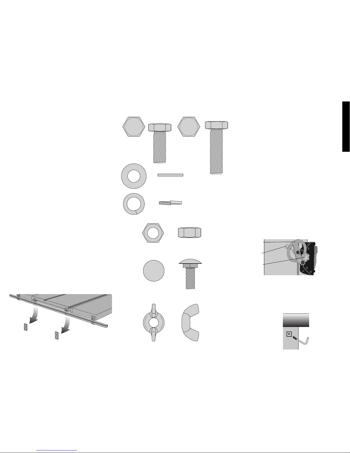
Hardware Included with the
DW7463 Heavy Duty Outfeed Table
M 10 NUT 16 mm HEX
(10 pieces)
Carriage Bolt
10 mm x 20 mm
(2 pieces)
FLAT WASHER
(10 PIECES)
10 MM LOCK WASHER
(10 PIECES)
BOLT
10 MM X 25 MM
(6 PIECES)
10 mm WING NUT
(2 pieces)
BOLT
10 MM X 35 MM
(4 PIECES)
Table saw Preparation: If you purchased the Outfeed
Table as an add-on accessory, start with this section. If
you purchased your Outfeed Table with your DW746
Woodworker’s Table Saw, skip to the assembly section.
• If you have no other accessories (52" Rail System or
Slide Table) on your saw, remove the rear rail and
associated hardware...
• ...OR with another accessory in place remove the rear
support brackets (Fig. 1) from between the saw table
and the rear rail. Do not remove the rear rail.
• Continue with Assembly, starting at Step 14.
Assembly
If you have other accessories (Slide Table and/or 52" Rail
System) completely assemble them first. Then return to
this manual to complete Outfeed Table Assembly, starting
at step 14.
PLEASE READ ENTIRE ASSEMBLY SECTION
BEFORE PROCEEDING.
STEP 1. Remove parts box, motor cover, fence beam, and
side tables from saw packaging.
STEP 2. Turn the saw right side up. You will need help.
The combined weight of the table top and motor is
approximately 200 lbs.
STEP 3. Cut and remove plastic strap holding the motor.
STEP 4. Using front hand crank, lower the motor some
and remove the foam packing material between the
motor and the mechanism.
STEP 5. Install bevel crank (Fig. 2). To do this, first
install the crank handle (A) over the shaft (B), rotate
slightly to fully engage the shaft pin. Screw the lock
knob (C) into place until it is fully seated, then back it
off 1/4 to 1/2 turn.
STEP 6. Using height crank, raise mechanism up as high
as it will go.
STEP 7. Install wrench hook (Fig. 3). On the front right
leg, near the top is a plastic threaded insert. Thread
the "L" shaped wrench hook in until no threads are visible.
A
B
C
FIG. 2
FIG. 3
Page 5
English
FIG. 6
FIG. 7
STEP 11.Parallel the front rail to the saw table (Fig. 6).
Using your fence face or a straightedge to extend the
table surface over the rail, make sure the distance from
the saw table top to the rail top is the same at both the
left and right side of the table. If the rail is not aligned
correctly, loosen the mounting screws slightly and tap
on the rail with a soft hammer or a regular hammer and
a block of wood until the distances are the same.
Tighten the hardware securely.
STEP 12. Attach left and right support tables (Fig. 7).
You will need: 6 - 10 x 25mm hex head bolts
6 - 10mm flat washers
6 - 10mm lock washers
Without the support table in place, install the 3 bolts per
side with washers as shown keeping 1/4" gap. Rest a
support table on the bolts, fitting into the notches. Using
the extruded fence face as a straightedge, flush the
support table to the saw table edge and snug the front
bolt. Repeat this process for the rear bolt and the center bolt. Tighten hardware. Repeat on the other side.
STEP 13. Attach front rail bracket to support tables (Fig
4).
You will need: 2 - 10 x 25mm flat head screws
2 - 10mm flat washers
2 - 10mm lock washers
2 - 10mm nuts
Align front bracket with support table and tighten bracket nut to the rail. Attach the support tables to the outer
front rail support brackets, keeping the washers and
nut on the inside of the table. Using the fence face as
a straight edge, make sure the front outer corner of the
support table is level with the inner edge and main
table surface.
Tighten hardware, including the 8mm rail support
bracket nut. Repeat this procedure for the other support table.
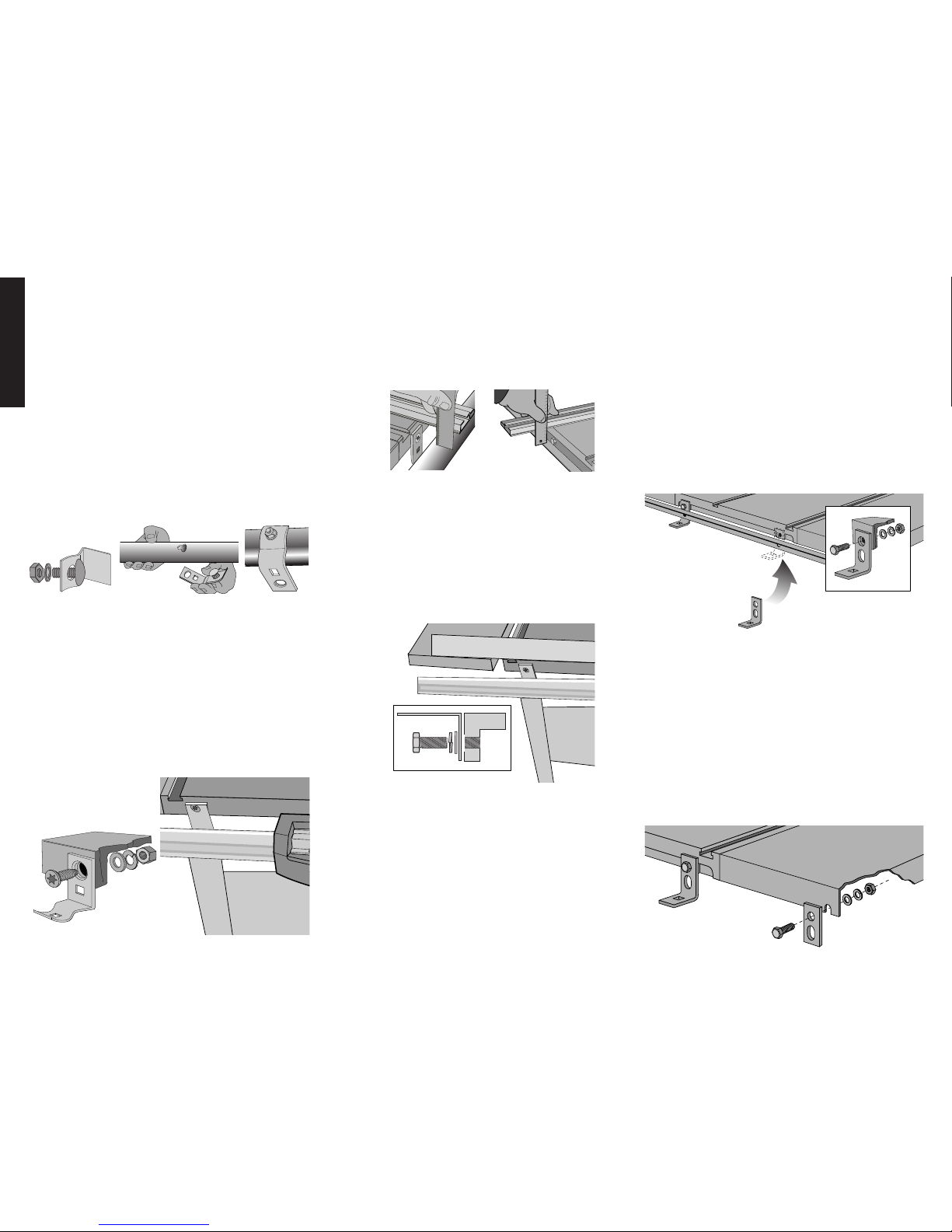
STEP 14. Attach hanger brackets to saw table (Fig. 8).
You will need: 2 - 10 x 35mm hex head bolts
2 - 10mm flat washers
2 - 10mm lock washers
2 - 10mm nuts
Secure a bolt through the square hole in each bracket
with a flat washer, lock washer, and nut, keeping the
washers and nuts to the inside of the table. When tightening nuts, keep the brackets positioned square to the
table. (With another accessory in place, insure the
hanger brackets are placed between the rear rail and
the saw table.)
STEP 15. Attach two rear support brackets (Fig. 9).
(With other accessories in place, rear support bracket(s) are not needed. The rear rail will attach directly to
the accessory).
You will need: 2 - 10 x 25mm hex head bolts
2 - 10mm flat washers
2 - 10mm lock washers
2 - 10mm nuts
Secure a bolt through the round hole in each bracket
with a flat washer, lock washer, and a nut, keeping the
washers and nut to the inside. Make sure hardware is
placed to the top of the slot in the rear of the support
table(s) and tighten. When tightening, keep the brackets positioned square to the table.
FIG. 8
FIG. 9
STEP 8. Unpack rail carton (contains front & rear rail) and
Outfeed Table carton.
STEP 9. Assemble front rail and brackets (Fig. 4).
You will need: 4 - 8mm carriage bolts (3 if adding a
Slide Table)
4 - 8mm lock washers
4 - 8mm nuts
Assemble carriage bolts, washers and nuts to front rail
brackets (just a few threads). Put the head of the carriage bolts into the keyhole slots in the front rail and
slide to engage the square part of the bolt. Run nut
until it is finger tight Repeat for other three brackets (If
you are also adding a Slide Table accessory, the left
most front rail bracket is not needed). When attaching
brackets to the rail, the rail must be positioned so that
the rip scale is right side-up. Also all 4 brackets should
face the same direction
STEP 10. Attach front rail with brackets to the table
top (Fig. 5)
You will need: 2 - 10 x 30mm flat head screws
2 - 10mm flat washers
2 - 10mm lock washers
2 - 10mm nuts
Secure each screw through the upper hole in the center brackets keeping the flat washer, lock washer and
nut to the inside of the table. Tighten snug but not very
tight. Tighten center rail bracket 8mm nuts, leaving the
outer ones finger tight.
FIG. 4
FIG. 5
Page 6
English
STEP 17. Parallel the rear rail to the table top (Fig. 6).
Using your fence face or a straightedge to extend the
table surface over the rail, make sure the distance from
the table top to the rail top is the same at both the left
and right side of the table. If the rail is not aligned correctly, loosen the hardware slightly and tap on the rail
with a soft hammer or a regular hammer and a block of
wood until the distances are the same. Tighten the
hardware securely. Repeat procedure to parallel rear
rail to accessories (if applicable).
STEP 18. Parallel the rear rail to support table(s)
(Fig. 7). Using your fence face as a straightedge, make
sure the rear outer corner of the support table is level
with the inner edge and main table surface. Adjust if
necessary and tighten hardware. Repeat this procedure for the other support table (if applicable).
STEP 19. Assemble the outfeed table (Fig. 11).
You will need: 2 - 10 x 25mm hex head bolts
2 - 10mm flat washers
2 - 10mm lock washers
2 - 10mm nuts
Place the table on the floor, flat side down. Mount the two
remaining hanger brackets using two M10 x 25 bolts.
Secure each bolt through the square hole in the short
leg of the bracket with a flat washer, lock washer, and
nut (Fig 11). Tighten snug only.
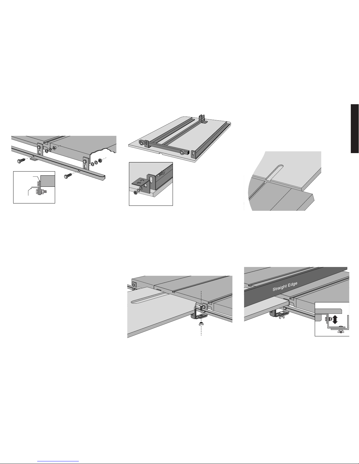
STEP 16. Position rear rail as shown and attach (Fig. 10).
You will need: 4 - 10 x 35mm hex head bolts
4 - 10mm flat washers
4 - 10mm lock washers
4 - 10mm nuts
TABLE
REAR SUPPORT
BRACKET
INVERTED
REAR RAIL
FIG. 10
STEP 20. Unfold the leg set by depressing the locking
buttons on both sides and swinging the leg set upward
until the locking buttons engage.
STEP 21. Place the outfeed table into position (Fig. 12).
You will need: 2 - 10mm carriage bolts
2 - 10mm wing nuts
Position table so the hanger brackets on the outfeed
table are on top of the brackets on the table saw. Place
the carriage bolts down through the square holes in
the brackets and secure each with a wing nut. Tighten
securely.
FIG. 11
FIG. 12
STEP 22. Check Outfeed Table miter clearance slot
alignment. Place miter gauge into right hand miter slot
in the saw table. Slide miter gauge beyond the rear of
the saw table and into the clearance slot in the Outfeed
Table top. Outfeed Table should not interfere with the
smooth operation of the miter gauge. If necessary,
loosen the M10 x 25 hardware (Fig. 13) holding the
table to the hanger brackets and tap on the outfeed
table with a soft hammer or a regular hammer and a
block of wood until clearance slot is aligned.
STEP 23. Parallel outfeed table to the table top.
Outfeed table should be level with or slightly below the
table top. For the edge closest to the table use your
fence face or a straightedge to extend the saw table
surface over the outfeed table. To align the tables tap
on the outfeed table with a soft hammer or a regular
hammer and a block of wood until they are parallel.
Tighten the M10 X 25 hardware holding the outfeed
table to the hanger brackets securely (Fig. 14). Using
the adjustable feet on the bottom of the leg set, level
the rear of the outfeed table to match its front edge.
FIG. 13
STEP 24. See DW746 manual for Table Saw operating
instruction and adjustments.
FIG. 14
Page 7

English
Additional Information
Removal and Storage:
• The outfeed table can be easily taken off by removing
the carriage bolts and wing nuts. Remove the outfeed
table from the back of the saw. Fold leg set down, locking into place, and table is ready for storage. Replace
hardware into hanger brackets for safe keeping
Cleaning:
• The table board of your Outfeed table is a composite
material, excessive moisture can cause deterioration.
Cleaning with a damp cloth or a mild solvent on the top
surface is acceptable, but the edges of the board
should not be wetted.
Adjust the rear fence glide
If necessary, adjust the rear glide to locate it correctly
against the rear rail by loosening the two screws which
secure it to the fence beam. The plastic retaining clip
should be deflected somewhat when the glide is positioned correctly. This adjustment should only be necessary if the rear rail has been relocated by the addition of
an optional accessory.
Page 8

Français
DeWalt… GARANTI SOLIDE
Les outils industriels de haute performance DeWalt sont fabriqués pour les
applications en construction et industrielles les plus rudes. La conception
de chaque outil dans la gamme – des perceuses aux ponceuses et aux
scies à table – est le résultat d’un emploi dans des conditions rigoureuses
sur le tas dans tous les secteurs d’activité. Chaque outil est fabriqué avec
une précision méticuleuse au moyen de systèmes de fabrication sophistiqués et d’un contrôle intensif de la qualité. Chaque outil est contrôlé avant
qu’il ne quitte l’usine afin de vérifier qu’il satisfait à nos normes de durabilité, fiabilité et puissance.
DeWALT Fabriqué pour les travaux durs...NOUS LE GARANTISSONS.
AVERTISSEMENT : POUR VOTRE PROPRE SÉCURITÉ, LISEZ LE GUIDE D’UTILISATION AVANT D’UTILISER LA SCIE • PORTEZ TOUJOURS DES LUNETTES DE PROTECTION DES YEUX • NE
PORTEZ PAS DE GANTS, DE CRAVATE, DE BIJOUX OU DE VÊTEMENTS AMPLES • ATTACHEZ VOS CHEVEUX S’ILS SONT LONGS • GARDEZ VOS MAINS ET VOS DOIGTS HORS DU TRAJET DE
LA LAME — FAITES EXTRÊMEMENT ATTENTION SI VOUS BISEAUTEZ • UTILISEZ TOUJOURS LE PROTECTEUR DE LA LAME ET L’ÉCARTEUR POUR TOUTE OPÉRATION POUR LAQUELLE IL PEUT
ÊTRE UTILISÉ Y COMPRIS SCIER • UTILISEZ UN « POUSSOIR » AU BESOIN • SACHEZ ÉVITER LES REBONDS — VOIR LE GUIDE • SOUTENEZ TOUJOURS VOTRE TRAVAIL AVEC LA TABLE ET
LE GUIDE OU LE CALIBRE À ONGLETS • N’UTILISEZ JAMAIS LE GUIDE ET LE CALIBRE À ONGLETS ENSEMBLE • NE PASSEZ JAMAIS LAMAIN AUTOUR OU AU DESSUS DE LA LAME • MONTEZ
BIEN LA LAME AVANT DE L’UTILISER • NE RETIREZ JAMAIS DES MORCEAUX COINCÉS OU COUPÉS TANT QUE L’ALIMENTATION N’EST PAS ÉTEINTE ET QUE LA LAME N’EST PAS ARRÊTÉE •
N’EXPOSEZ PAS CET OUTIL À LA PLUIE ET NE L’UTILISEZ PAS DANS DES LIEUX HUMIDES • NE LE FAITES PAS FONCTIONNER EN CAS D’ÉTAT D ’ÉBRIÉTÉ OU D’ÉTAT DROGUÉ • MANQUER DE
RESPECTER CES CONSIGNES PEUT RÉSULTER DANS DES BLESSURES GRAVES.
AVERTISSEMENT : L’UTILISATION DE CET OUTIL PEUT GÉNÉRER DES POUSSIÈRES
CONTENANT DES PRODUITS CHIMIQUES CONNUS POUR ÊTRE À L’ORIGINE DE CANCERS,
DE MALFORMATIONS CONGÉNITALES OU AUTRES ENDOMMAGEMENTS DU SYSTÈME REPRODUCTIF.
UTILISEZ UN APPAREIL RESPIRATOIRE APPROPRIÉ.
Page 9

Français
Articles inclus
• (1) table de sortie DW7463
• (1) sac de quincaillerie
Outils requis
• (2) clés 16 mm ou 5/8 po à extrémités ouvertes
• mètre
• marteau mou ou régulier et un bloc de bois
Pour accélérer le montage, les outils suivants seraient les bien-
venus :
• clé à douilles 16 mm ou 5/8 po
Quincaillerie requise
Le sac de quincaillerie inclus contient tous les articles, écrous,
boulons et rondelles nécessaires au montage des composants de
la table de sortie DW7463 et à sa fixation sur la scie à table pour
travail du bois DW746. (Lors du montage en tant qu’accessoire
supplémentaire, utilisez les articles de quincaillerie neufs à la
place des articles démontés).
Pour faciliter le montage de votre scie/accessoire, appariez les
écrous, boulons et rondelles avec le tableau des articles de quincaillerie. Avant chaque étape, consultez le tableau et identifiez
les articles dont vous avez besoin.
Préparation de la scie à table : Si vous avez acheté la table de
sortie comme un accessoire rajouté, commencez par cette section. Si vous avez acheté la table de sortie avec la scie à table
pour travail du bois DW746, passez à la section montage.
• Si vous ne disposez d’aucun autre accessoire (système de
rails 52 po (132,08cm) ou table coulissante) sur votre scie,
retirez le rail dorsal et les articles de quincaillerie associés...
• ...OU si un autre accessoire est en place, retirez les fixations
de support dorsal (Fig. 1) présentes entre la table de la scie
et le rail dorsal. Ne retirez pas le rail dorsal.
• Continuez avec le montage en commençant à l’étape 14.
Montage
Si vous disposez d’autres accessoires (table coulissante et/ou
système de rails 52 po (132,08 cm)) montez les complètement
d’abord. Puis revenez au présent guide pour achever le montage
de la table de sortie en commençant à l’étape 14.
VEUILLEZ LIRE COMPLÈTEMENT LA SECTION MONTAGE
AVANT DE PROCÉDER.
ÉTAPE 1. Retirez la boîte des composants, le panneau couvrant
le moteur, le montant du guide et les tables latérales hors de
l’emballage de la scie.
ÉTAPE 2. Retournez la scie pour mettre le côté droit en haut.
Vous aurez besoin d’aide. Le poids combiné du dessus de
table et du moteur est d’environ 200 lb.
ÉTAPE 3. Coupez et retirez les lanières en plastique qui retien-
nent le moteur.
ÉTAPE 4. Au moyen de la manivelle frontale, abaissez un peu le
moteur et retirez la mousse d’emballage entre le moteur et le
mécanisme.
ÉTAPE 5. Installer la manivelle à biseau (Fig. 2). Pour cela,
installez d’abord la poignée de la manivelle (A) sur le manche
(B) puis faites tourner légèrement pour enclencher complètement l’ergot du manche. Vissez le bouton de verrouillage (C)
en place jusqu’à ce qu’il soit complètement enfoncé, puis
dévissez-le de 1/4 à 1/2 tour.
ÉTAPE 6. Au moyen de la manivelle de réglage de la hauteur
soulevez le mécanisme jusqu’au niveau le plus haut possible.
ÉTAPE 7. Installer le crochet-clé (Fig. 3). Sur la jambe frontale
droite, presque tout en haut se trouve un insert en plastique
fileté. Vissez le crochet-clé en forme de « L » jusqu’à ce que
seulement quelques pas de vis soient visibles.
A
B
C
FIG. 2
FIG. 1
FIG. 3
Articles de quincaillerie inclus avec
la table de sortie usage intensif
DW7463
ÉCROU HEXAGONAL
M 10 16 MM
(10 PIÈCES)
BOULON DE
CARROSSERIE
10 MM X 20 MM
(2 PIÈCES)
RONDELLE PLATE
(10 PIÈCES)
RONDELLE D’ARRÊT
10 MM
(10 PIÈCES)
BOULON
10 MM X 25 MM
(6 PIÈCES)
ÉCROU À OREILLES
10 MM
(2 PIÈCES)
BOULON
10 MM X 35 MM
(4 PIÈCES)
Page 10

Français
ÉTAPE 8. Déballez le carton des rails (contenant les rails frontal
et dorsal) et celui de la table de sortie.
ÉTAPE 9. Monter le rail frontal et les fixations (Fig. 4).
Vous aurez besoin de :
4 – boulons de carrosserie 8 mm (3 si vous
ajoutez une table coulissante)
4 – rondelles d’arrêt 8 mm
4 – écrous 8 mm
Montez les boulons de carrosserie, les rondelles et les écrous
sur les fixations du rail frontal (juste quelques pas de vis).
Mettez la tête des boulons de carrosserie dans les fentes
dans le rail frontal et faites glisser pour enclencher la partie
carrée du boulon . Vissez manuellement l’écrou pour le serrer et répétez la procédure pour les trois autres fixations (si
vous ajoutez aussi une table coulissante, la fixation à l’ex-
trême gauche du rail frontal est inutile). Pendant la fixation
des fixations sur le rail, le rail doit être positionné de manière
que l’échelle longitudinale ait le côté droit vers le haut. Les 4
fixations doivent aussi toutes regarder dans la même direction.
ÉTAPE 10. Attacher le rail frontal avec les fixations au
dessus de la table (Fig. 5).
Vous aurez besoin de :
2 – vis à tête plate 10 x 30 mm
2 – rondelles plates 10 mm
2 – rondelles d’arrêt 10 mm
2 – écrous 10 mm
Fixez chaque vis à travers le trou supérieur dans les fixations
centrales en positionnant la rondelle plate, la rondelle d’arrêt
et l’écrou sur le côté interne de la table. Serrez pour ajuster
mais pas trop. Serrez les écrous de 8 mm des fixations centrales du rail, en conservant le seul serrage manuel pour les
plus extérieures.
FIG. 4
FIG. 5
FIG. 6
FIG. 7
ÉTAPE 11 Placer le rail frontal parallèlement au dessus de la
table de la scie (Fig. 6). En utilisant le devant du guide ou
une règle de vérification pour prolonger la surface de la table
par dessus le rail, assurez-vous que la distance du haut de la
table de la scie au haut du rail est la même du côté droit et du
côté gauche de la table. Si le rail n’est pas correctement
aligné, desserrez légèrement les vis de montage et tapotez
sur le rail avec un marteau mou ou un marteau régulier et un
bloc en bois jusqu’à ce que les distances soient identiques.
Serrez à fond les articles de quincaillerie.
ÉTAPE 12. Attacher les tables de support droite et gauche (Fig.
7). Vous aurez besoin de :
6 – boulons à tête hexagonale 10 x 25 mm
6 – rondelles plates 10 mm
6 – rondelles d’arrêt 10 mm
La table de support n’étant pas en place, installez 3 écrous de
chaque côté avec des rondelles comme montré en maintenant un espace de 1/4 po (6,36 mm). Faites reposer la table
de support sur les écrous, en l’encastrant dans les encoches.
En utilisant le guide comme une règle de vérification, faites
araser la table de support avec le bord de la table de la scie
et ajustez le boulon frontal. Répétez ce procédé pour le
boulon dorsal et le boulon central. Serrez tous les articles de
quincaillerie. Répétez pour l’autre côté.
ÉTAPE 13. Attacher la fixation du rail frontal aux tables de
support (Fig. 4). Vous aurez besoin de :
2 – vis à tête plate 10 x 25 mm
2 – rondelles plates 10 mm
2 – rondelles d’arrêt 10 mm
2 – écrous 10 mm
Alignez la fixation frontale avec la table de support et serrez
l’écrou de la fixation au rail. Attachez les tables de support à la
fixation extérieure de support du rail frontal en positionnant les
rondelles et l’écrou sur le côté interne de la table. En utilisant
le devant du guide comme une règle de vérification, assurezvous que le coin extérieur frontal de la table de support est de
niveau avec le coin interne et la surface principale de la table.
Serrez tous les articles de quincaillerie, y compris l’écrou de
la fixation de support du rail 8 mm. Répétez cette procédure
pour l’autre table de support.
ÉTAPE 14. Attacher les fixations pour suspendre à la table de
la scie (Fig. 8). Vous aurez besoin de :
2 – boulons à tête hexagonale 10 x 35 mm
2 – rondelles plates 10 mm
2 – rondelles d’arrêt 10 mm
2 – écrous 10 mm
Fixez un boulon à travers le trou carré dans chaque fixation
avec pour chacun une rondelle plate, une rondelle d’arrêt et
un écrou en positionnant les rondelles et l’écrou sur le côté
interne de la table. Pendant le serrage des écrous, maintenez
les fixations à l’équerre avec la table. (Si un autre accessoire
est en place, assurez-vous que les fixations pour suspendre
sont placées entre le rail dorsal et la table de la scie.)
ÉTAPE 15. Attacher les deux fixations de support dorsal (Fig.
9). (Si d’autres accessoires sont en place, les fixations de
support dorsal sont inutiles. Le rail dorsal s’attachera directement à l’accessoire).
Vous aurez besoin de :
2 – boulons à tête hexagonale 10 x 25 mm
2 – rondelles plates 10 mm
2 – rondelles d’arrêt 10 mm
2 – écrous 10 mm
Fixez un boulon à travers le trou rond dans chaque fixation
avec pour chacun une rondelle plate, une rondelle d’arrêt et
un écrou en positionnant les rondelles et l’écrou à l’intérieur.
Assurez-vous que ces articles se trouvent en haut de chaque
fente au dos de la (les) table(s) de support et serrez. Alors que
vous serrez, maintenez les fixations à l’équerre avec la table.
FIG. 8
FIG. 9
Page 11

Français
ÉTAPE 17 Placer le rail dorsal parallèlement au dessus de la
table de la scie (Fig. 6). En utilisant le devant du guide ou
une règle de vérification pour prolonger la surface de la table
par dessus le rail, assurez-vous que la distance du dessus de
la table au haut du rail est la même du côté droit et du côté
gauche de la table. Si le rail n’est pas correctement aligné,
desserrez légèrement les vis de montage et tapotez sur le rail
avec un marteau mou ou un marteau régulier et un bloc en bois
jusqu’à ce que les distances soient identiques. Serrez à fond
les articles de quincaillerie. Répétez la procédure pour placer
le rail dorsal parallèlement aux accessoires (si applicable).
ÉTAPE 18. Placer le rail dorsal parallèlement à la table de
support (Fig. 7). En utilisant le devant du guide comme une
règle de vérification, assurez-vous que le coin extérieur dorsal
de la table de support est de niveau avec le coin interne et la
surface principale de la table. Ajustez si nécessaire et serrez
les articles de quincaillerie. Répétez cette procédure pour
l’autre table de support (si applicable).
ÉTAPE 19. Monter la table de sortie (Fig. 11).
Vous aurez besoin de :
2 – boulons à tête hexagonale 10 x 25 mm
2 – rondelles plates 10 mm
2 – rondelles d’arrêt 10 mm
2 – écrous 10 mm
Posez la table par terre, le côté plat contre le sol. Montez les
deux fixations pour suspendre restantes au moyen des deux
boulons M10 x 25. Fixez chaque boulon à travers le trou carré
dans la jambe courte de la fixation avec une rondelle plate,
une rondelle d’arrêt et un écrou (Fig. 11). Serrez pour ajuster.
ÉTAPE 16. Positionner le rail dorsal comme montré et l’at-
tacher (Fig. 10). Vous aurez besoin de :
4 – boulons à tête hexagonale 10 x 35mm
4 – rondelles plates 10 mm
4 – rondelles d’arrêt 10 mm
4 – écrous 10 mm
TABLE
REAR SUPPORT
BRACKET
INVERTED
REAR RAIL
FIG. 10
ÉTAPE 20. Dépliez le jeu de jambes en appuyant sur les bou-
tons de verrouillage des deux côtés et en balançant le jeu de
jambes vers le haut jusqu’à ce que les boutons de verrouillage
s’enclenchent.
ÉTAPE 21. Mettre en place la table de sortie (Fig. 12).
Vous aurez besoin de :
2 – boulons de carrosserie 10 mm
2 – écrous à oreilles 10 mm
Positionnez la table de façon que les fixations pour suspendre
de la table de sortie se trouvent par dessus les fixations de la
scie à table. Introduisez les boulons de carrosserie à travers
les trous carrés des fixations et fixez-les, chacun avec un
écrou à oreilles. Serrez à fond.
FIG. 11
FIG. 12
ÉTAPE 22. Vérifiez l’alignement des fentes de dégagement
des onglets de la table de sortie. Placez le calibre à onglets
dans la fente de l’onglet à main droite de la table de la scie.
Faites glisser le calibre à onglets au delà du dos de la table de
la scie pour l’introduire dans la fente de dégagement du
dessus de la table de sortie. La table de sortie ne doit pas
gêner le fonctionnement du calibre à onglets. Au besoin,
desserrez les articles M10 x 25 (Fig. 13) attachant la table aux
fixations pour suspendre et tapotez sur la table de sortie avec
un marteau mou ou un marteau régulier et un bloc de bois
jusqu’à ce que la fente de dégagement soit alignée.
ÉTAPE 23. Placer la table de sortie parallèlement au dessus
de la table. La table de sortie doit être de niveau avec le
dessus de la table ou légèrement plus basse. Pour le bord le
plus proche de la table, servez-vous du devant du guide ou
d’une règle de vérification pour prolonger la surface de la
table de la scie par dessus la table de sortie. Pour aligner les
tables, tapotez sur la table de sortie avec un marteau mou ou
un marteau régulier et un bloc de bois jusqu’à ce qu’elles
soient parallèles. Serrez à fond les articles M10 X 25
attachant la table de sortie aux fixations pour suspendre (Fig.
14). Grâce au pied réglable en bas du jeu de jambes, abaissez le dos de la table de sortie de façon qu’il soit à la même
hauteur que le bord frontal.
FIG. 13
ÉTAPE 24. Voir le guide DW746 pour le mode d’emploi et le
réglage de la scie à table.
FIG. 14
Page 12

Français
Information supplémentaire
Démontage et Stockage :
• La table de sortie peut aisément être démontée en retirant les
boulons de carrosserie et les écrous à oreilles. Retirez la
table de sortie du dos de la scie. Pliez le jeu de jambes, qui
se verrouille ainsi, et la table est prête à être stockée.
Remettez les articles dans les fixations pour suspendre afin
de les ranger en lieu sûr.
Nettoyage :
• Le panneau de la table de sortie est constitué d’un matériau
composé et une humidité excessive peut le détériorer. Le nettoyage avec une éponge humide ou un solvant doux de la surface du panneau est acceptable mais les bords du panneau
ne doivent pas être mouillés.
Régler la bande de glissement
arrière du guide
Au besoin, régler la bande de glissement arrière pour l’appuyer correctement sur le rail arrière en desserrant les
deux vis qui le fixent à la poutrelle du guide. L’étrier en
plastique est légèrement dérivé quand la bande de glissement est bien placée. Ce réglage est nécessaire uniquement si le rail arrière est replacé après l’ajout d’un accessoire optionnel.
Page 13

Español
DeWalt… garantizado resistente
Las herramientas de alto rendimiento industrial de DeWalt están fabricadas para soportar las más rudas aplicaciones en la industria y la construcción en los Estados Unidos. El diseño de cada herramienta de la línea
–desde los taladros, las lijadoras y hasta las sierras de mesa– son el resultado de riguroso uso en los sitios de trabajo y a través de la industria. Cada
herramienta es producida con ardua precisión, usando los más avanzados
sistemas de manufactura y un intenso control de calidad. Cada herramienta es revisada antes de salir de la fábrica para asegurarle que cumple
con sus estándares de durabilidad, confiabilidad y potencia.
DeWALT Fabricado fuerte como el lugar de trabajo…LO
GARANTIZAMOS.
ADVERTENCIA: PARASU PROTECCIÓN PERSONAL, LEA EL MANUAL DE INSTRUCCIONES ANTES DE OPERAR LASIERRA • USE SIEMPRE PROTECCIÓN PARA LOS OJOS • NO USE GUANTES,
CORBATAS, JOYERÍA O ROPA SUELTA • AMARRE EL CABELLO LARGO • MANTENGA LAS MANOS Y DEDOS FUERA DEL CAMINO DE LASIERRA — ESPECIALMENTE AL BISELAR • USE SIEMPRE
EL PROTECTOR DE LAHOJA YEL SEPARADOR PARA CADA OPERACIÓN DONDE PUEDASER USADA, INCLUYENDO EL CORTE FRANCO • USE UNA«VARILLA DE EMPUJE» CUANDO SE REQUIERA
• APRENDA COMO EVITAR LOS CONTRAGOLPES — VEA EL MANUAL • APOYE SIEMPRE EL TRABAJO CON LA MESAY GUARDA O EL MEDIDOR DE LA ESCUADRA DE INGLETES • NUNCAUSE
EL MEDIDOR DE LA ESCUADRA DE INGLETES Y LA GUARDAAL MISMO TIEMPO • NUNCAALCANCE ALREDEDOR O SOBRE LA SIERRA • ASEGURE LA SIERRA MONTADA ANTES DE OPERAR •
NUNCA QUITE PIEZAS ATORADAS O ATASCADAS HASTA DESCONECTAR LA SIERRA Y QUE ÉSTA SE HAYA DETENIDO • NO EXPONGA A LA LLUVIA O LUGARES HÚMEDOS • NO OPERE ESTA
MÁQUINA BAJO LA INFLUENCIA DEL ALCOHOL O DROGAS • EL INCUMPLIMIENTO CON ESTAS ADVERTENCIAS PUEDE RESULTAR EN GRAVES LESIONES PERSONALES.
ADVERTENCIA: EL USO DE ESTA HERRAMIENTA PUEDE GENERAR POLVO QUE CONTENGA
COMPUESTOS QUÍMICOS QUE PUEDEN CAUSAR CÁNCER, DEFECTOS DE NACIMIENTO U
OTROS DAÑOS AL SISTEMA REPRODUCTIVO. USE LA PROTECCIÓN RESPIRATORIAAPROPIADA.
Page 14

Español
Artículos incluidos
• (1) Subconjunto de la mesa de salida de material DW7463
• (1) Bolsa con herrajes
Herramientas requeridas
• (2) Llave de extremo abierto de 16 mm
• Regla
• Martillo suave o regular y bloque de madera
Para hacer más rápido el ensamblado, lo siguiente sería de
ayuda:
• Dado de 16 mm
Herrajes necesarios
La bolsa de con herrajes que se incluye contiene todas las tuercas, pernos y arandelas necesarias para ensamblar los componentes incluidos con la mesa de salida de material para instalarla en la sierra de mesa para carpintero DW7463 (Cuando se
instale como accesorio adicional use herrajes nuevos en lugar de
los herrajes extraídos).
Para facilitar el ensamblado de su banco/sierra, iguale las tuercas, pernos y arandelas con la gráfica de herrajes. Antes de
cada paso, revise sus herrajes contra la gráfica e identifique las
piezas que necesita.
Preparación de la sierra de mesa: Si compró usted la mesa de
salida de material como accesorio adicional, empiece con esta
sección. Si usted compró su mesa de salida de material con la
sierra de mesa para carpintero DW7463, vaya hasta la sección
de ensamblado.
• Si no tiene otros accesorios (Sistema de rieles de 1.32m o
mesa deslizante) en su sierra, extraiga el riel posterior y los
herrajes asociados...
• ...o con algún otro accesorio en su lugar, extraiga los pun-
tales de soporte posterior (Fig. 1) entre la mesa de aserrar
y el riel posterior. No extraiga el riel posterior.
• Continúe con el ensamble empezando en el paso 14.
FIG. 1
Ensamblado
Si tiene usted otros accesorios (Mesa deslizante y/o el Sistema
de rieles de 1.32m) ensámblelos primero. Después regrese a
este manual para terminar el ensamblado de la mesa de salida
de material, empezando en el paso 14.
ANTES DE PROCEDER, LEA TODA LA SECCIÓN
DE ENSAMBLADO.
PASO 1. Retire la caja de partes, la cubierta del motor, guía, y las
mesas laterales del paquete de la sierra.
PASO 2. Voltee la sierra con el lado derecho hacia arriba.
Necesitará ayuda. El peso combinado de la cubierta de la
mesa y el motor es de 90 kilos aproximadamente.
PASO 3. Corte y retire los flejes plásticos que sujetan el motor.
PASO 4. Usando la manivela del frente, baje un poco el motor y
retire el material de espuma de empaque entre el motor y el
mecanismo.
PASO 5. Instale la manivela de biselado (Fig. 2). (Fig. 2) Para
hacer esto, instale primero la manivela (A) en la flecha (B),
gire ligeramente para enganchar el pasador de la flecha.
Atornille la perilla de seguridad (C) en su lugar hasta que esté
completamente asentada en su lugar y luego afloje 1/4 a 1/2
vuelta.
PASO 6. Usando la manivela de altura, levante el mecanismo tan
alto como llegue.
PASO 7. Instale el gancho para llaves de tuercas (Fig. 3).
(Fig. 3) En la pata delantera derecha, cerca de la parte de
arriba hay un injerto de plástico roscado. Enrosque uno de
los ganchos de llave en forma de «L» hasta que sólo unas
cuantas vueltas de rosca sean visibles.
A
B
C
FIG. 2
FIG. 3
Herrajes incluidos con
la mesa de salida para trabajo
pesado DW7463
M 10 TUERCA HEXAGONAL
16MM
(10 PIEZAS)
PERNO DE CARRUAJE
10 MM X 20MM
(2 PIEZAS)
ARANDELA PLANA
(10 PIEZAS)
10 MM ARANDELA
DE SEGURIDAD
(10 PIEZAS)
PERNO
10 MM X 25 MM
(6 PIEZAS)
10 MM TUERCA
MARIPOSA
(2 PIEZAS)
PERNO
10 MM X 35 MM
(4 PIEZAS)
Page 15

Español
PASO 8. Desempaque la caja del riel (contiene el riel posterior y
frontal) y la caja de la mesa de salida de material.
PASO 9. Ensamblado del riel frontal y soportes (Fig. 4).
Necesitará:4 – 8 mm pernos de carruaje (3 si está insta-
lando una mesa deslizante)
4 arandelas de seguridad de 8mm
4 tuercas de 8mm
Ensamble los pernos de carruaje, arandelas y tuercas a los
soportes del riel frontal (sólo unas cuantas roscas). Coloque
la cabeza de los pernos de carruaje en las ranuras en el riel
frontal y deslice para enganchar la parte cuadrada del perno.
Enrosque la tuerca con la mano hasta que apriete, repita para
los otros tres soportes (Si también está instalando una mesa
deslizante, no necesita el soporte frontal de extrema izquierda). Cuando coloque los soportes en el riel, el riel debe estar
colocado de manera que la escala para corte al hilo esté con
el lado derecho hacia arriba. Además, los cuatro soportes
deberán ver en la misma dirección.
Paso 10. Instale el riel frontal con los soportes a la mesa.
(Fig. 5)
Necesitará: 2 tornillos de cabeza plana de 10 x 30mm
2 arandelas planas de 10mm
2 arandelas de seguridad de 10mm
2 tuercas de 10mm
Asegure cada tornillo a través del orificio superior de los puntales de soporte del centro, dejando las arandelas planas,
arandelas de seguridad y tuercas en el interior de la mesa.
Apriete un poco pero no mucho. Apriete las tuercas de 8 mm
de los soportes del riel central, dejando las de afuera apretadas a mano.
FIG. 4
FIG. 5
FIG. 6
FIG. 7
PASO 11. Alinee en paralelo el riel posterior con la superficie
de la mesa de aserrar (Fig. 6). Use la cara de la cara de la
guía o una regla para extender la superficie de la mesa sobre
el riel, cerciórese que la distancia desde la parte superior de
la mesa al lado superior del riel es igual del lado izquierdo y
derecho de la mesa. Si el riel no está alineado correctamente, afloje ligeramente los tornillos de montaje y golpee
suavemente con un martillo suave o un martillo regular y un
bloque de madera hasta que la distancia sea la misma.
Apriete los herrajes.
PASO 12. Instale las cubiertas de soporte izquierda y
derecha de la mesa (Fig. 7).
Necesitará: 6 Pernos de 10 x 25mm de cabeza hexagonal
6 arandelas planas de 10mm
6 arandelas de seguridad de 10mm
Sin la mesa de soporte en su lugar, instale los tres pernos con
arandelas por lado, como se muestra dejando un claro de 1/4”
(6 mm). Descanse una mesa de soporte en los pernos, acomodando en las muescas. Usando la cara extruida de la guía
como regla, ajuste la mesa de soporte al paño con la orilla de
la mesa de aserrar y apriete el perno del frente. Repita este
procedimiento para el perno trasero y el perno central.
Apriete los herrajes. Repita en el otro lado.
PASO 13. Instale el soporte del riel frontal a la mesa de
soporte (Fig. 4).
Necesitará: 2 tornillos de cabeza plana de 10 x 25mm
2 arandelas planas de 10mm
2 arandelas de seguridad de 10mm
2 tuercas de 10mm
Alinee el soporte frontal con la cubierta de la mesa de soporte
y apriete la tuerca contra el riel. Instale las mesas de soporte
a los puntales de soporte externo del riel frontal, dejando las
arandelas y tuerca del lado interno de la mesa. Usando la
cara de la guía como regla, asegúrese que la esquina exterior
delantera de la mesa de soporte está nivelada con la orilla
interna y la superficie principal de la mesa.
Apriete los herrajes, incluyendo la tuerca de 8 mm del puntal
de soporte del riel. Repita este procedimiento para la otra
mesa de soporte.
PASO 14. Instale los soportes colgantes en la cubierta de la
mesa de aserrar (Fig. 8).
Necesitará: 2 Pernos de 10 x 35mm de cabeza
hexagonal
2 arandelas planas de 10mm
2 arandelas de seguridad de 10mm
2 tuercas de 10mm
Asegure el perno a través del orificio cuadrado en cada soporte
con una arandela plana, arandela de seguridad y tuerca,
dejando las arandelas y tuerca en el lado interno. Cuando
apriete las tuercas, mantenga los soportes cuadrados con la
mesa. (Con otro accesorio en su lugar, asegure que los
soportes colgantes estén colocados entre el riel posterior y la
cubierta de la mesa de aserrar).
PASO 15. Instale dos puntales de soporte posterior (Fig. 9).
(Con otros accesorios en su lugar, el/los soporte(s) posteriores no son necesarios. El riel posterior se instalará directamente al accesorio).
Necesitará: 2 Pernos de 10 x 25mm de cabeza hexagonal
2 arandelas planas de 10mm
2 arandelas de seguridad de 10mm
2 tuercas de 10mm
Asegure el perno a través del orificio redondo en cada
soporte con una arandela plana, arandela de seguridad y
tuerca, dejando las arandelas y tuerca en el lado interno.
Cerciórese que los herrajes sean colocados en la parte superior de la ranura en el lado posterior de las mesas de soporte
y apriete. Cuando apriete las tuercas, mantenga los soportes
cuadrados con la mesa.
FIG. 8
FIG. 9
Page 16

Español
PASO 17. Alinee en paralelo el riel posterior con la superficie
de la mesa (Fig. 6). Use la cara de de la guía o una regla
para extender la superficie de la cubierta de la mesa sobre el
riel, cerciórese que la distancia desde la parte superior de la
cubierta de la mesa al lado superior del riel es igual del lado
izquierdo y derecho de la cubierta de la mesa. Si el riel no
está alineado correctamente, afloje ligeramente los tornillos
de montaje y golpee suavemente con un martillo suave o un
martillo regular y un bloque de madera hasta que las distancias sean iguales. Apriete los herrajes. Repita el procedimiento para alinear en paralelo el riel posterior con los accesorios (si se aplica).
PASO 18. Alinee en paralelo el riel posterior con la(s) cubier-
tas de la(s) mesa(s) de soporte. (Fig. 7). Usando la cara de
la guía como regla, asegúrese que la esquina exterior
delantera de la cubierta de la mesa de soporte está nivelada
con la orilla interna y la superficie principal de la cubierta de la
mesa. Ajuste si es necesario y apriete los herrajes. Repita
este procedimiento para la otra mesa de soporte (si es aplicable).
PASO 19. Ensamble la mesa de salida (Fig. 11).
Necesitará: 2 Pernos de 10 x 25mm de cabeza hexagonal
2 arandelas planas de 10mm
2 arandelas de seguridad de 10mm
2 tuercas de 10mm
Coloque la mesa en el piso, con el lado plano hacia abajo.
Monte los dos soportes colgantes remanentes usando dos
pernos M10 x 25. Asegure cada perno a través del orificio
cuadrado en la pata corta del soporte con una arandela plana,
arandela de seguridad y tuerca (Fig 11). Apriete al llegue
solamente.
PASO 16. Coloque el riel posterior como se muestra e instale
(Fig. 10).
Necesitará: 4 Pernos de 10 x 35mm de cabeza hexagonal
4 arandelas planas de 10mm
4 arandelas de seguridad de 10mm
4 tuercas de 10mm
TABLE
REAR SUPPORT
BRACKET
INVERTED
REAR RAIL
FIG. 10
PASO 20. Desdoble el juego de patas presionando los botones
de fijación en ambos lados y moviendo el juego de patas
hacia arriba hasta que se enganchen los botones de fijación.
PASO 21. Coloque la mesa de salida en posición (Fig. 12).
Necesitará: 2 pernos de carruaje de 10 mm
2 Tuercas mariposa de 10 mm
Coloque la mesa de manera que los soportes colgantes de la
mesa de salida estén sobre los soportes de la sierra de mesa.
Inserte los pernos de carruaje hacia abajo a través de los orificios cuadrados en los soportes y asegure cada uno con una
tuerca mariposa. Apriete completamente.
FIG. 11
FIG. 12
PASO 22. Revise la alineación de despeje de las ranuras de
la mesa de salida de material. Coloque la regla de ingletes
en la ranura de ingletes derecha de la mesa de aserrar.
Deslice la regla de ingletes detrás del lado posterior de la
mesa de aserrar y dentro de la ranura de despeje en la mesa
de salida. La mesa de salida no deberá interferir con el funcionamiento de la regla de ingletes. Si es necesario, afloje los
herrajes M10 x 25 (Fig. 13) que sujetan la mesa en los
soportes colgantes y golpee suavemente con un martillo
suave o un martillo regular y un bloque de madera hasta alinear
la ranura de despeje.
PASO 23. Alinee en paralelo la mesa de salida con la super-
ficie de la mesa. La mesa de salida deberá estar nivelada o
ligeramente debajo de la superficie de la mesa. Para la orilla
más cercana a la mesa de aserrar use una regla o la cara de
la guía para extender la superficie de la mesa de aserrar
sobre la mesa de salida. Para alinear las mesas, golpee
suavemente sobre la mesa del riel usando un martillo suave
o un bloque de madera hasta que estén paralelas. Apriete los
herrajes M10 X 25 sujetando firmemente la mesa de salida
contra los soportes colgantes (Fig. 14). Usando las bases
ajustables en la parte inferior del juego de patas, nivele la orilla posterior de la mesa de salida con la orilla frontal de la
misma.
FIG. 13
FIG. 14
Page 17

Español
Ajuste el deslizador de la gua
trasera
En caso necesario, ajuste el deslizador trasero para colocarlo correctamente contra el riel trasero aflojando los dos
tornillos que lo fijan a la viga de la gua. La pinza de
retencin de plstico debe inclinarse cuando el deslizador
queda correctamente colocado. Este ajuste solamente es
necesario si el riel trasero se ha movido por la adicin de
un accesorio opcional.
 Loading...