

Page 1

DEWALT Industrial Tool Co., 701 East Joppa Road, Baltimore, MD 21286 (FEB03) Form No. 394050-01
DW7461 Copyright © 1999,2000
Page 2

INSTRUCTION MANUAL
GUIDE D'UTILISATION
MANUAL DE INSTRUCCIONES
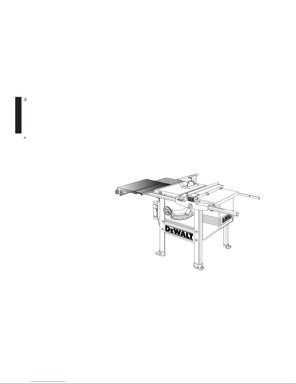
DW7461
Heavy Duty Slide Table
Table coulissante usage intensif
Mesa deslizante para trabajo pesado
For Use Only With DEWALT DW746 Table Saw
A utiliser seulement avec les scies à table D
EWALT DW746
Para uso sólo con la Sierra de Mesa D
EWALT DW746
INSTRUCTIVO DE OPERACIÓN, CENTROS DE SERVICIO Y PÓLIZA
DE GARANTIA. ADVERTENCIA: LEASE ESTE INSTRUCTIVO ANTES
DE USAR EL PRODUCTO. SI TIENE DUDAS, POR FAVOR LLAME.
Before returning this
product call
1-800-4-DEWALT
IF YOU SHOULD EXPERIENCE A PROBLEM WITH YOUR DEWALT PURCHASE,
CALL 1-800-4 DEWALT.
IN MOST CASES, A DEWALT REPRESENTATIVE CAN RESOLVE
YOUR PROBLEM OVER THE PHONE.
IF YOU HAVE A SUGGESTION OR COMMENT, GIVE US A CALL.
YOUR FEEDBACK IS VITAL TO THE SUCCESS OF DEWALT'S
QUALITY IMPROVEMENT PROGRAM.
See our catalog on the World Wide Web. www.dewalt.com
Page 3
English
D
EWALT… GUARANTEED TOUGH
DEWALT high performance industrial tools are made for
America’s toughest industrial and construction applications. The
design of every tool in the line – from drills to sanders to table
saws – is the result of rigorous use on job sites and throughout
industry. Each tool is produced with painstaking precision using
advanced manufacturing systems and intense quality control.
Every tool is checked before it leaves the factory to make sure
that it meets your standards for durability, reliability and power.
D
EWALT Built Job site Tough…WE GUARANTEE IT.
WARNING: FOR YOUR OWN SAFETY, READ INSTRUCTION MANUAL BEFORE OPERATING SAW • ALWAYS WEAR EYE PROTECTION • DO NOT WEAR
GLOVES, NECKTIES, JEWELRY OR LOOSE CLOTHING • CONTAIN LONG HAIR • KEEP HANDS AND FINGERS OUT OF THE SAW BLADE PATH — USE EXTRA
CAUTION WHEN BEVELING • ALWAYS USE BLADE GUARD AND SPREADER FOR EVERY OPERATION FOR WHICH IT CAN BE USED, INCLUDING THROUGH
SAWING • USE A “PUSH STICK” WHEN REQUIRED • KNOW HOW TO AVOID KICKBACKS — SEE MANUAL • ALWAYS SUPPORT WORK WITH TABLE AND
FENCE OR MITER GAUGE • NEVER USE FENCE AND MITER GAUGE TOGETHER • NEVER REACH AROUND OR OVER SAW BLADE • SECURELY MOUNT
SAW BLADE BEFORE OPERATING • NEVER REMOVE JAMMED OR CUT-OFF PIECES UNTIL POWER IS OFF AND BLADE HAS STOPPED • DO NOT EXPOSE
TO RAIN OR USE IN DAMP LOCATIONS • DO NOT OPERATE THIS MACHINE WHILE UNDER THE INFLUENCE OF ALCOHOL OR DRUGS • FAILURE TO COMPLY WITH THESE WARNINGS MAY RESULT IN SERIOUS PERSONAL INJURY.
WARNING: USE OF THIS TOOL CAN GENERATE DUST CONTAINING CHEMICALS
KNOWN TO CAUSE CANCER, BIRTH DEFECTS OR OTHER REPRODUCTIVE HARM.
USE APPROPRIATE RESPIRATORY PROTECTION.
Page 4
English
1
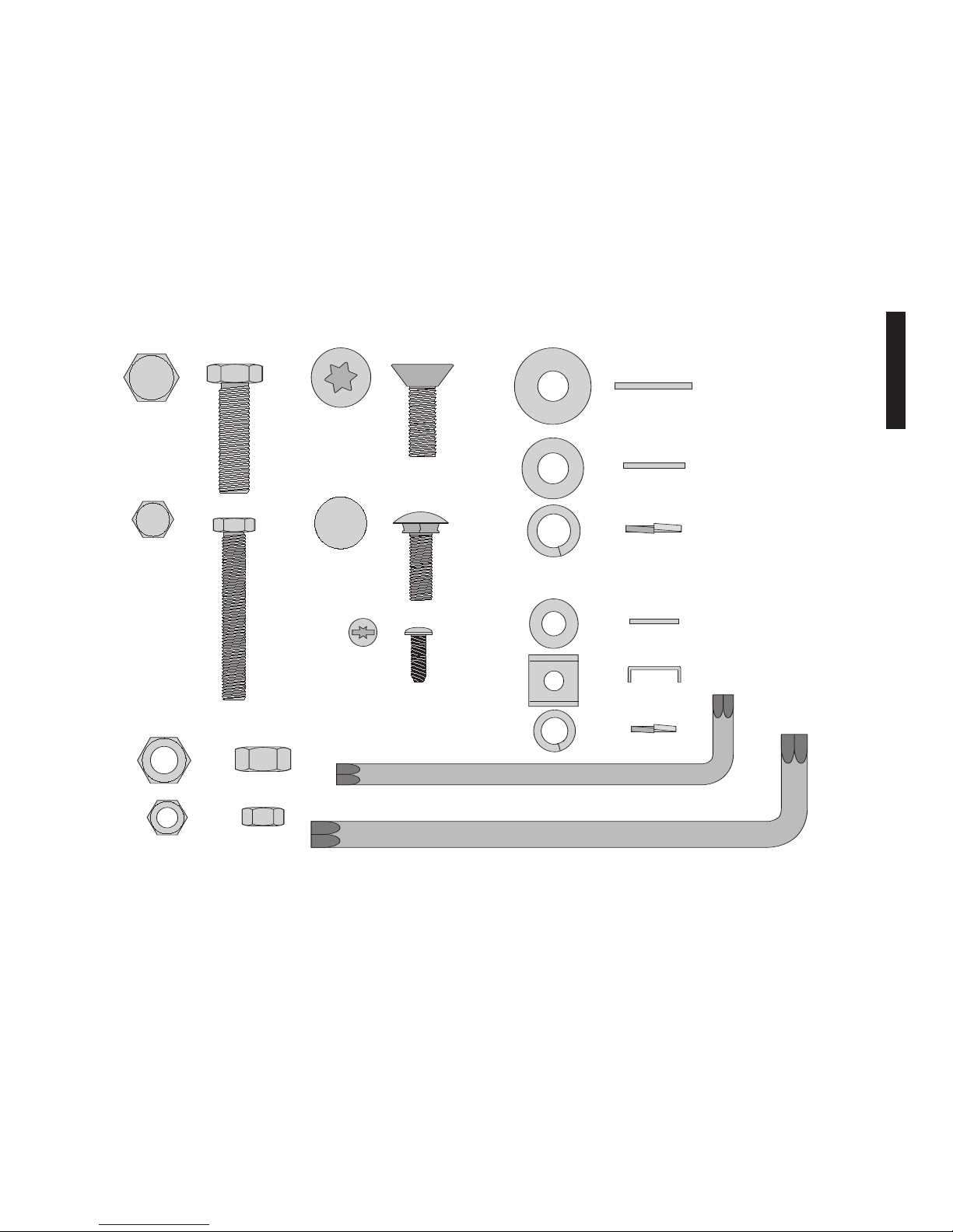
M 10 NUT 16 mm HEX
(11 pieces)
Carriage Bolt
8 mm x 25 mm
(2 pieces)
BOLT
10 mm x 35 mm
(11 pieces)
BOLT
8 mm x 55 mm
(4 pieces)
T50 TORX
Flat Head Screw
10mm X 30mm
(3 pieces)
Screw
5mm x 16 mm
(2 pieces)
10MM LARGE
FLAT WASHER
(8 PIECES)
10MM FLAT WASHER
(7 PIECES)
10 MM LOCK WASHER
(11 PIECES)
8MM FLAT WASHER
(2 PIECES)
LEG CLAMP
BRACKET
(4 PIECES)
8 MM LOCK WASHER
(10 PIECES)
M 8 NUT 13 mm HEX
(10 pieces)
T40 TORX
WRENCH (1)
T50 TORX
WRENCH (1)
Hardware Included with the DW7461 Heavy Duty Slide Table
Page 5
STEP 12. Unpack Slide Table carton.
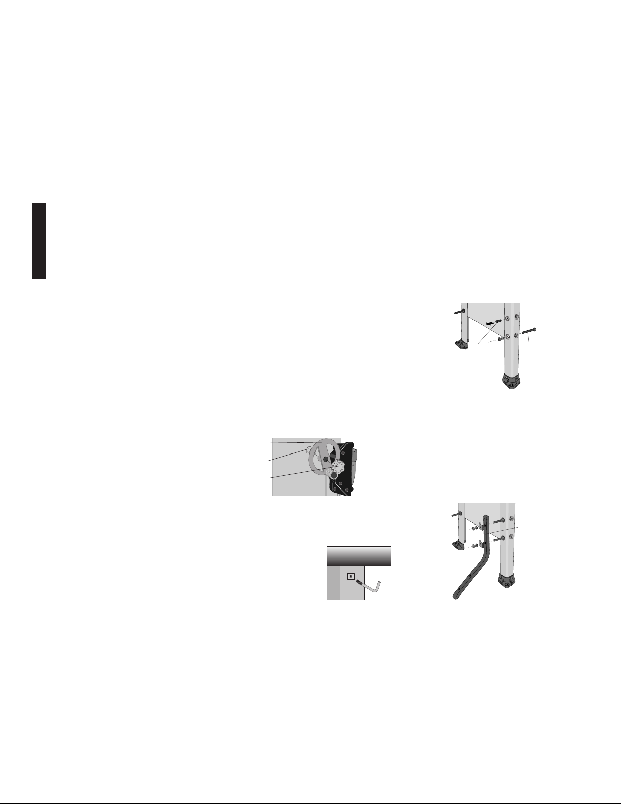
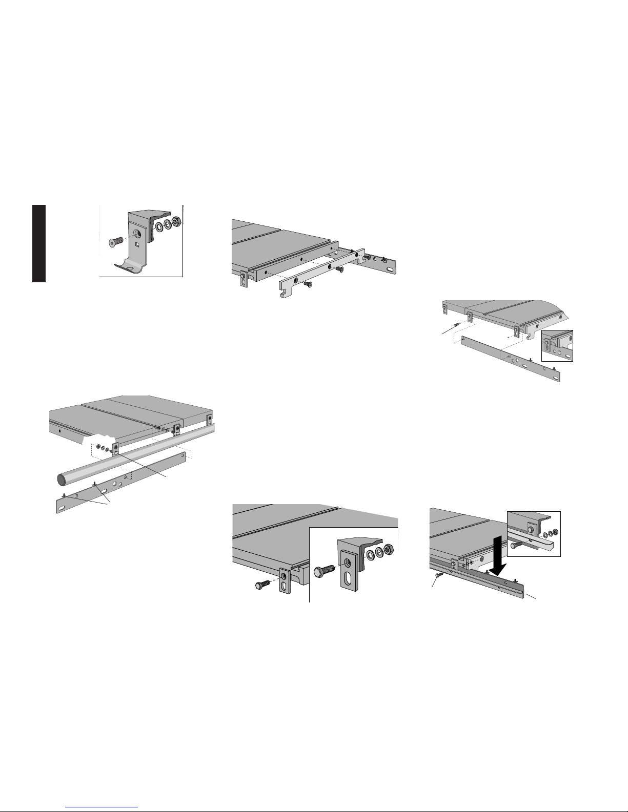
STEP 13. Replace table saw leg screws (Fig. 3).
You will need: 4 - 8 x 55mm hex head bolts
4 - 8mm lock washers
4 - 8mm nuts
Working on one bolt at a time, remove M8 cap screws
and replace with an M8 x 55 hex head bolt (Do not
remove all M8 cap screws at the same time.) Install
bolt from the inside of the table saw and secure with a
lock washer and nut, fully tighten and insure that washer and nut are within the depression on the leg.
Continue, one at a time, until all four M8 bolts on the
left side of the saw have been replaced.
STEP 14. Install stabilizing legs on saw.
You will need: 4 - Leg clamp brackets
4 - 8mm lock washers
4 - 8mm nuts
The legs can be installed in either of two positions
depending on whether you are using a mobile base
(DW7460). Without the mobile base, the legs are
installed with the identification mark (hole) toward the
top as shown in figure 4. If a mobile base is installed,
then the identification mark is toward the bottom.
Secure the stabilizing legs to the saw using the leg
clamp brackets, lock washers, and nuts. Snug the
nuts, but do not tighten.
English
2
Items Included
• (1) Slide Table sub-assembly
• (1) Support bracket
•(2) Support rail
• (3) Rear support bracket
• (2) Stabilizing leg
• (1) Miter gauge
• (1) Miter gauge stop
•(1) Miter gauge clamp
•(1) Hardware bag
Tools Included
•Torx T40 wrench
• Torx T50 wrench
Tools Needed
• (2) 16mm or 5/8" open end wrench
• 13mm or 1/2" open end wrench
• Ruler
• Soft hammer or regular hammer and block of wood
• Small flat blade screwdriver
To speed assembly, the following would be helpful:
• 16mm or 5/8" socket wrench
• 13mm or 1/2" socket wrench
Necessary Hardware
The included hardware bag contains all the necessary
nuts, bolts, and washers to assemble the components
included with the DW7461 Slide Table and to attach it to
the DW746 Woodworker’s Table Saw (When attaching as
an add-on use new hardware in place of removed hardware).
To make assembly of your saw/accessory easier, match
the nuts, bolts, and washers with the hardware chart.
Before each step, check your hardware against the chart
and identify the pieces you need.
PLEASE READ ENTIRE ASSEMBLY SECTION
BEFORE PROCEEDING.
Assembly
If you have other accessories (52" Rail System and/or
Outfeed Table) assemble the 52" Rail system first, except
for attaching the front and rear rail. Then return to this
manual at Step 16. Outfeed Table should be assembled
last.
Table saw Preparation: If you are adding the DW7461
Sliding Table to an existing DW746 saw, disassemble the
saw as described in steps 1 through 4. If your saw is not
yet assembled, begin assembly with step 5.
STEP 1: Remove rear fence rail. Unbolt and remove the
rear fence rail. If you have a 52” rail system or an outfeed support table which uses mounting brackets to
support the rail leave the brackets in place.
STEP 2 : Remove front fence rail. Remove the front fence
rail from the mounting brackets by unscrewing the
8MM nuts on the bottom and lifting straight up.
STEP 3: Remove front rail brackets. Remove the fence
rail mounting brackets from the saw by unscrewing the
T50 flat head screws.
STEP 4 : Remove left side support table. Loosen the
three M10 bolts holding the left support table to the
table saw. You can now lift the support table up and
off. Finish removing the hardware.
IF THE SAW IS NEW, COMPLETE STEPS 5-11. IF NOT
SKIP TO STEP 12.
STEP 5 : If the saw is new, remove parts box, motor cover,
fence beam, and side tables from saw packaging.
Unpack rail carton containing front and rear rails.
STEP 6. If the saw is new, turn the saw right side up. You
will need help. The combined weight of the table top
and motor is approximately 200 lbs.
STEP 7. Cut and remove plastic strap holding the motor.
STEP 8. Using front hand crank, lower the motor some
and remove the foam packing material between the
motor and the mechanism.
STEP 9. Install bevel crank (Fig. 1). To do this, first
install the crank handle (A) over the shaft (B), rotate
slightly to fully engage the shaft pin. Screw the lock
knob (C) into place until it is fully seated, then back it
off 1/4 to 1/2 turn.
STEP 10. Using height crank, raise mechanism up as
high as it will go.
STEP 11. Install wrench hook (Fig. 2). On the front right
leg, near the top is a plastic threaded insert. Thread
the "L" shaped wrench hook in
until only a few threads are vis-
ible.
A
B
C
FIG. 1
FIG. 2
FIG. 3
ADD
REMOVE
FIG. 4
ID
MARK
Page 6
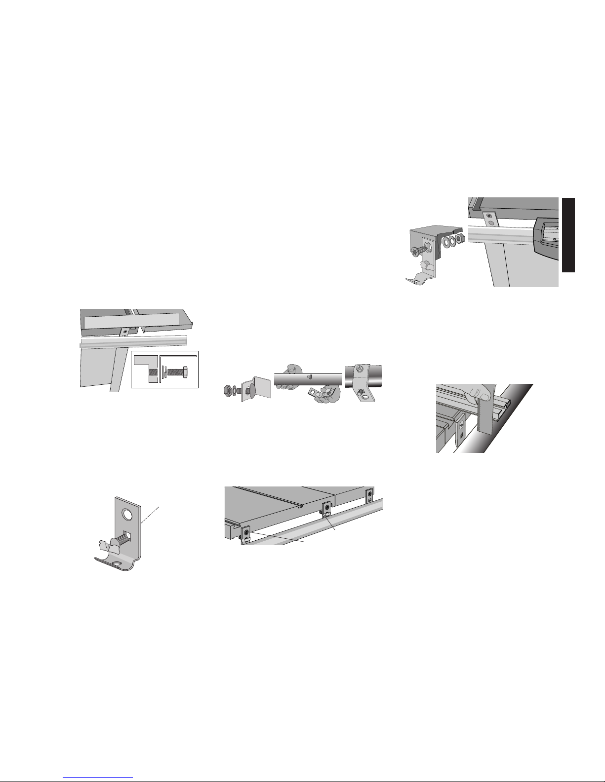
STEP 18. Install mounting brackets to fence rail tube
(Fig. 7). You will need:
3 - 8 x 20mm carriage bolts
3 - 8mm lock washers
3 - 8mm nuts
3 - mounting brackets (2 from step 17
above plus one more)
(Your saw is shipped with four fence rail mounting
brackets, but the left most bracket is not used with the
sliding table attachment, and can be set aside.)
Place the fence rail tube so that the scale reads
correctly.
Insert the three 20mm carriage bolts through the holes
on the curved face of each mounting bracket, and
loosely place a lock washer and nut on them. Put the
head of each carriage bolt into the keyhole slot of the
fence rail and slide them sideways to engage. The two
brackets with the additional carriage bolt taped in
place, are used for the middle keyholes. The third
bracket is used in the right most keyhole. Make sure all
three brackets face toward the rear of the fence rail.
Snug the nuts up, but do not tighten them all the way.
STEP 19. Attach fence rail tube to saw (Fig. 8 and 9).
You will need:
2 - 10 x 30mm flat head screws
2 - 10mm flat washers
2 - 10mm lock washers
2 - 10mm nuts
Secure the middle two brackets of the fence rail tube to
the tablesaw top using the screws, washers, and nuts.
The washers and nuts should be on the inside edge of
the table. Snug the nuts, but do not tighten them.
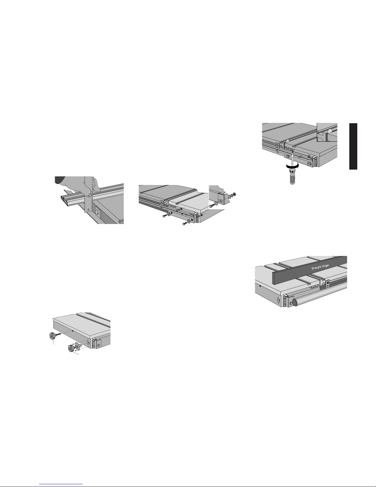
STEP 20. Parallel the front fence rail tube to the saw
table (Fig. 10). Before you adjust the height of the
fence rail tube, tighten the two nuts that hold the tube
to the mounting brackets.
Place a straight edge on the table extending out over
the rail tube (you can use the aluminum fence from
your saw as a straight edge). Using a ruler and this
straight edge, check to see if both ends of the rail rube
are the same distance below the table. If you need to
raise or lower one side of the tube, use a rubber mallet, or a hammer and a block of wood to prevent denting the tube and tap on the rail gently. Fully tighten the
mounting bolts.
STEP 21. Attach front rail bracket to support table (Fig. 11)
(If you have a 52” Rail System, skip this step)
You will need: 1 - 10 x 30mm flat head screw
1 - 10mm flat washer
1 - 10mm lock washer
1 - 10mm nut
Align front bracket with the support table and tighten
bracket nuts to the rail. Attach the support table to the
outer front rail support bracket, keeping the washers
and nut on the inside of the table. Using the fence face
as a straight edge, make sure the front outer corner of
the support table is level with the inner edge and main
table surface. Tighten hardware, including the 8mm rail
support bracket nut.
3
FIG. 10
STEP 15. Adjust stabilizing legs by sliding them down
until they contact the floor. Tighten hardware securely.
STEP 16. Attach right side support table (Fig.5).
(If the support table is already installed or you have a
52" Rail System, skip this step.)
You will need: 3 - 10 x 25mm hex head bolts
3 - 10mm flat washers
3 - 10mm lock washers
Without the support table in place, install the 3 bolts in
the right side with washers as shown keeping 1/4" gap.
Rest a support table on the bolts, fitting into the notches. Using the extruded fence face as a straightedge,
flush the support table to the saw table edge and snug
the front bolt. Repeat this process for the rear bolt and
the center bolt. Tighten hardware securely.
STEP 17. Install slide rail bolts to front fence mount-
ing brackets. (Fig. 6)
You will need: 2 - fence rail mounting brackets
2 - 8 x 25mm carriage bolts (no wahers
or nuts at this time)
2 - small pieces of tape
Insert the two 25mm carriage bolts through the square
holes on the flat side of two of the mounting brackets.
The head of the bolt should face forward as shown in
Fig. 5 . Temporarily hold them in place with a piece of
tape. This is done before mounting the brackets to the
rail, because you will not be able to insert these bolts
afterwards.
FIG. 7
FIG. 9
M8 x 10
TAPE
FIG. 8
FIG. 6
FIG.5
English
Page 7
STEP 22. Install front Slide Table support rails. (Fig.
12)
You will need: 2 - 8mm flat washers
2 - 8mm lock washers
2 - 8mm nuts
Examine the two sliding table support rails to determine
which one is for the front and which one is for the rear.
The front rail will have the height adjustment screws to
the left side, and behind the face as shown.
The sliding table front rail is secured to the backside of
the front fence rail mounting brackets using the carriage bolts temporarily taped in place previously.
Position the front rail over the taped carriage bolts, and
add the washers and nuts. Snug the nuts down, but do
not tighten.
STEP 23. Attach slide table support bracket (Fig. 13).
You will need: 3 - 10 x 30mm flat head screws
Place tab on the end of the support bracket through the
rectangular hole in the slide table support rail, line up
countersunk holes in support bracket with threaded
holes in side of table saw table. Using the included T50
torx wrench, install three M10 x 30 screws directly into
the table, no washers or nuts needed. Tighten securely.
Ensure that the screw heads are flush with or recessed
below the bracket surface.
STEP 24. To prevent the rail from sagging over time and
causing misalignment with the slide table, pre-stress
the rail downward. Apply downward pressure to left
end of front slide table support rail so right end will rock
up into contact with underside of table saw table. Fully
tighten nuts on M8 carriage bolts.
STEP 25. Install rear mounting brackets. (Fig. 14)
You will need: 3 - flat mounting brackets
3 - 10 x 35mm hex head bolts
3 - 10mm flat washers
3 - 10mm lock washers
3 - 10mm nuts
If you have either the 52” fence accessory or the outfeed support table, you can use the existing supports
instead of installing a new one. Skip this step.
Attach the two mounting brackets to the tablesaw top
using the bolts, washers, and nuts, as shown in Fig.
14. Tighten securely. The brackets are mounted using
the round holes, and the slotted holes will hang below
the table top.
Attach the third mounting bracket to the rear of the right
hand support table. The bracket is mounted using the
round hole into the slot in the support table.
When tightening nuts, keep the brackets positioned
square to the table.
English
FIG. 12
M8 CARRIAGE
(TAPED IN PLACE)
ADJUSTING HARDWARE
(ORIENTED AS SHOWN)
STEP 26. Install the rear sliding table support rail. (Fig. 15)
You will need: 2 - 10 x 35mm hex head bolts
2 - 10mm flat washers
2 - 10mm lock washers
2 - 10mm nuts
The rear sliding table support rail mounts inside the
brackets installed previously, and also locks onto the
tab of the support bracket similar to the way the front
rail is mounted. Temporarily insert the left side bolt and
nut to support the rail until you position the rear fence
support rail in the next step.
STEP 27. Install the rear fence support rail (Fig. 16).
If you are installing the sliding table to an existing saw,
take note that the rear fence support rail is inverted
from your original installation. The fence support rail
uses the same bolts as the sliding table support rail, but
is mounted on the outside of the brackets. Install the
right-hand bolt, washers and nut, and snug them up
without tightening. Remove the temporary bolt from the
left-hand bracket you installed above, and reinsert it
through the fence support rail bracket, and sliding table
support rail. The right-hand end of the fence support
rail should be even with the sliding table support rail.
APPLY DOWNWARD
PRESSURE
4
FIG. 14
FIG. 15
FIG. 16
FIG. 11
FIG. 13
TEMP. BOLT
(LEFT SIDE)
RIGHT SIDE BOLT
SHOULD BE
EVEN
Page 8
English
5
STEP 28. Tighten rear rail and slide table support
bracket (Fig. 17). Facing the back of the saw, apply
downward pressure to right end of slide table support rail
so left end will rock up into contact with underside of
table saw table. Lift up on rear fence support rail next to
left hand support bolt. Tighten hardware securely. Place
a straight edge ( the alminum fence supplied) on the
table extending out over the rear fence support rail.
Using a ruler and this straight edge, set the right side of
the rear fence support rail the same distance from the
table surface as the left hand side. Tighten right hand
hardware securely.
STEP 29. Attach rear fence support rail to right sup-
port table.
You will need: 1 - 10 x 35mm hex head bolt
1 - 10mm flat washer
1 - 10mm lock washer
1 - 10mm nut
Attach the rear fence support rail to the support bracket keeping the washers and nut to the inside. Using the
fence face as a straight edge, make sure the rear outer
corner of the support tabel is level with the inner edge
and main table surface. Tighten hardware securely.
STEP 30. Attach slide lock knob assembly (Fig. 18).
You will need: 2 - 5 x 16mm pan head screws
Set slide lock knob to "un-locked" position (pin most
retracted). Align mounting holes in lock knob housing
with the threaded holes in the slide table. Tighten
screws. Return knob to "locked" position, lock will
automatically engage and lock table.
STEP 31. Attach miter lock knob (Fig. 18). Screw lock
knob assembly into threaded hole in the slide table
until hand tight.
INSTALL SLIDE TABLE ONTO SUPPORT RAILS:
STEP 32. Slides in slide table are equipped with ship-
ping/alignment plugs to limit slide movement.
IMPORTANT: DO NOT remove shipping/alignment
plugs before slide table is fully installed.
STEP 33. Slide table is heavy. Use extreme caution when
lifting. Use two people to lift slide table.
STEP 34. Lift slide table out of shipping box and place
onto support rails.
STEP 35. You will need: 4 - 10 x 35mm hex head bolts
8 - Large 10mm flat washers
4 - 10mm lock washers
4 - 10mm nuts
In front of saw, place a large M10 washer on each bolt.
Install bolts through slots in slide table support pan and
support rails. In rear of saw, place a large M10 washer
between rear fence rail and slide table support pan.
(Fig. 19). Secure each bolt with a large M10 washer,
lock washer, and nut. Loosely tighten nut, then back off
one full turn. It may be necessary to align the flats on
the hex bolts with the rear rail.
STEP 36. Align slide table to saw table (Fig. 20). Prior
to adjustment, place the saw in it’s final location. Insure
that shipping/alignment plugs are in place. Using a
coin, feeler gauge or thick paper as a shim, push the
sliding table toward the saw table, but leave a clearance gap between them. The size of the gap is not
important, but should be relatively small and the two
tables should be parallel.
Adjust the height of the sliding table so it is approximately flush with the table saw top. The height adjustment screws are on the front and rear support rails.
Before completeing the final height adjustment of the
table, tighten the four mounting bolts to seat them in
their holes, but then loosen them again so the final
adjustment can be made. The bolts need to be loose
enough to allow the brackets to move up and down as
the height adjustment screws are turned.
STEP 37. Adjusting the height of the sliding table.
(Fig. 21) Prior to adjustment, insure that
shipping/alignment plugs are in place. Place a straight
edge across the tablesaw top and extended over the
sliding table top. Adjust the height of the sliding table
by turning the screws clockwise to raise the sliding
table until it is just slightly higher than the tablesaw top.
If you need to back the adjustment screws out, make
sure you press down on the table to ensure it is seated on the top of the screws.
When the height is correct, tighten the four mounting
bolts and re-check both the height and the side clearance with respect to the tablesaw top. Readjust as
necessary.
FIG. 19
FIG. 20
FIG. 17
STEP 38. Remove shipping/alignment plugs (Fig. 22).
This can be done by unlocking slide lock and giving the
slide table a firm push. Once shipping/alignment plugs
are removed, slide table should move freely. Save
shipping/alignment plugs, if slide table needs future
adjustment, is to be removed from saw, or is to be
transported, reinstall shipping/alignment plugs by lightly tapping plugs into end of ball bearing slide with small
mallet.
FIG. 18
MITER LOCK
KNOB
SLIDE LOCK KNOB
FIG. 21
Page 9
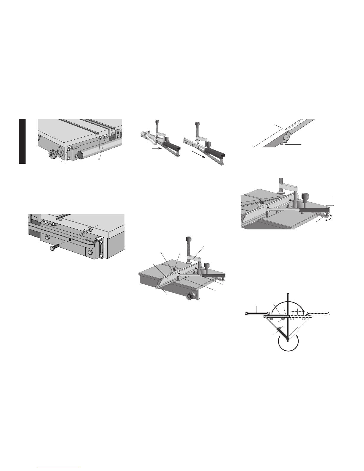
Miter Gauge Assembly - Fig. 25:
STEP 42. Attach fence to miter gauge. Loosen wing
nuts (D). Orient fence (A) and slide miter gauge (B)
locking bar to slot (C) in fence. Tighten thumb screws
(D) to lock fence into place, loosen thumb screws to
adjust.
STEP 43. Attach adjustable stop (E) to miter fence.
Slide adjustable stop locking hardware (F) into slot on
top of the fence. Tighten thumb screws to lock fence
into place, loosen thumb screws to adjust.
STEP 44. Attach quick release clamp (G) to miter
gauge. Put locking screw in full-up position. Orient
clamp pointing rearward and drop into top of miter
gauge. Turn clamp 180 degrees to retain.
Miter Gauge Use
Adjust miter gauge angle - Fig. 26
• Align mark on telescoping bar with end of housing (A).
Tighten thumb screw.
Angle Detent System - Fig. 26
• The miter gauge is equipped with a detent system for
easily setting the more frequently used angles. Adjust
miter gauge in the vicinity of the angle desired, press
and hold detent button (B) on bottom of beam and slide
scale in until the detent catches. Tighten thumb screw.
English
6
STEP 39. Re-check parallel of rails to the saw table top
(Fig. 17). Using your fence face or a straightedge to
extend the table surface over the rear fence rails, make
sure the distance from the saw table top to the rail top
is the same at both the left and right side of the saw
table. If a rail is not aligned correctly, loosen all mounting screws slightly and tap on the rail with a soft hammer or a regular hammer and a block of wood until the
distances are the same. Tighten the hardware
attached to the saw table securely. Repeat for the
remaining attachment points checking the distance
along the full length of the rail.
STEP 40. See DW746 manual for Table Saw operating
instruction and adjustments.
Miter Guage Assembly
STEP 41. Insert telescoping scale into housing.
Arrange miter gage as shown in Fig. 24. Insert telescoping scale bar into the housing. Align 90˚ mark with
end of outer housing. Tighten clamp.
Finish Table Saw Assembly:
Attach rear fence rail to Slide Table support pan (Fig. 23).
You will need: 1 - 10 x 35mm hex head bolt
1 - 10mm flat washer
1 - 10mm lock washer
1 - 10mm nut
Secure bolt with a flat washer, lock washer, and a nut.
Tighten hardware snug.
FIG. 23
Miter Gauge Calibration - Fig. 27
1. Set the miter gauge to 90˚ using the detent system.
2. Loosen eccentric lock screw (A). Inside housing using
hex key.
3. Turn eccentric (B) to adjust gauge to true 90˚ using calibration square. Tighten eccentric lock screw.
Reversing Miter Gauge - Fig. 28
The Miter Gauge can be reversed easily.
1. Loosen fence lock knobs (A), remove fence (B).
2. Remove lock knobs and fence clamp (C) from fence
base (D).
3. Loosen telescoping clamp (E) and pull angle scale out
of housing.
4. Rotate telescoping housing (F) to oposite side.
5. Rotate fence base to other side.
6. Re-enage degree scale into housing.
7. Re-install fence clamp and lock knobs.
8. Re-install fence and tighten clamp.
A
B
C
D
FIG. 24
E
F
G
A
FIG. 25
FIG. 26
B
FIG. 27
A
B
C
D
E
F
A
B
FIG. 28
SHIPPING/ALIGNMENT PLUGS
SHIPPING/ALIGNMENT
PLUGS
FIG. 22
Page 10

English
7
Operation of Slide Table
1. Install miter gauge in “T” slot in slide table in desired
location and angle. Adjust miter gauge fence approximately 1” from blade.
2. Tighten miter gauge lock knob on left side of slide table.
3. Move slide table toward operator and ensure that work
piece will clear blade. Cycle slide table and ensure that
end of miter gauge fence goes past blade centerline
and does not contact blade or blade guard.
4. Move slide table toward operator, place work piece on
slide table. Engage hold down clamp if needed. If using
flip stop, hold piece securely against flip stop and miter
gauge fence. Keep hold down clamp centered over
miter gauge bar. Do not overtighten clamp.
5. Turn on saw. Push slide table and work piece through
blade. Do not stand directly behind blade.
6. Turn off saw. Remove work piece. Return slide table to
home position.
Adjust the rear fence glide
If necessary, adjust the rear glide to locate it correctly
against the rear rail by loosening the two screws which
secure it to the fence beam. The plastic retaining clip
should be deflected somewhat when the glide is positioned correctly. This adjustment should only be necessary if the rear rail has been relocated by the addition of
an optional accessory.
Cleaning
Cleaning Slides:
STEP 1. Push Slide Table rearward as far as it will go.
Gently sweep sawdust off of slide table support pan.
Return slide table to its parked position.
STEP 2. To clean ball bearing slides, move slide table as
far forward as it will go. Using clean rag, gently wipe
exposed ball tracks on slides attached to support pan.
Look under slide table, gently wipe exposed ball tracks
on slides attached to underside of table. Push slide
table as far as it will go in other direction. Again, wipe
exposed ball tracks on slides attached to support pan
and underneath table.
Cleaning Slide Table:
• Protect your investment. Keep your slide table clean.
If you notice signs of rust on the table, steel wool the
areas. Clean with mineral spirits or denatured alcohol
and apply paste wax.
Page 11

Français
8
D
EWALT… GARANTI SOLIDE
Les outils industriels de haute performance DeWalt sont fabriqués pour les
applications en construction et industrielles les plus rudes. La conception
de chaque outil dans la gamme – des perceuses aux ponceuses et aux
scies à table – est le résultat d’un emploi dans des conditions rigoureuses
sur le tas dans tous les secteurs d’activité. Chaque outil est fabriqué avec
une précision méticuleuse au moyen de systèmes de fabrication sophistiqués et d’un contrôle intensif de la qualité. Chaque outil est contrôlé avant
qu’il ne quitte l’usine afin de vérifier qu’il satisfait à nos normes de durabilité, fiabilité et puissance.
DEWALT Fabriqué pour les travaux durs NOUS LE GARANTISSONS.
AVERTISSEMENT : POUR VOTRE PROPRE SÉCURITÉ, LISEZ LE GUIDE D’UTILISATION AVANT D’UTILISER LA SCIE • PORTEZ TOUJOURS DES LUNETTES DE PROTECTION DES YEUX • NE
PORTEZ PAS DE GANTS, DE CRAVATE, DE BIJOUX OU DE VÊTEMENTS AMPLES • ATTACHEZ VOS CHEVEUX S’ILS SONT LONGS • GARDEZ VOS MAINS ET VOS DOIGTS HORS DU TRAJET DE
LA LAME — FAITES EXTRÊMEMENTATTENTION SI VOUS BISEAUTEZ • UTILISEZ TOUJOURS LE PROTECTEUR DE LA LAME ET L’ÉCARTEUR POUR TOUTE OPÉRATION POUR LAQUELLE IL PEUT
ÊTRE UTILISÉ Y COMPRIS SCIER • UTILISEZ UN « POUSSOIR » AU BESOIN • SACHEZ ÉVITER LES REBONDS — VOIR LE GUIDE • SOUTENEZ TOUJOURS VOTRE TRAVAIL AVEC LATABLE ET
LE GUIDE OU LE CALIBRE À ONGLETS • N’UTILISEZ JAMAIS LE GUIDE ET LE CALIBRE À ONGLETS ENSEMBLE • NE PASSEZ JAMAIS LAMAIN AUTOUR OU AU DESSUS DE LA LAME • MONTEZ
BIEN LA LAME AVANT DE L’UTILISER • NE RETIREZ JAMAIS DES MORCEAUX COINCÉS OU COUPÉS TANT QUE L’ALIMENTATION N’EST PAS ÉTEINTE ET QUE LA LAME N’EST PAS ARRÊTÉE •
N’EXPOSEZ PAS CET OUTIL À LA PLUIE ET NE L’UTILISEZ PAS DANS DES LIEUX HUMIDES • NE LE FAITES PAS FONCTIONNER EN CAS D’ÉTAT D’ÉBRIÉTÉ OU D’ÉTAT DROGUÉ • MANQUER DE
RESPECTER CES CONSIGNES PEUT RÉSULTER DANS DES BLESSURES GRAVES.
AVERTISSEMENT : L’UTILISATION DE CET OUTIL PEUT GÉNÉRER DES POUSSIÈRES
CONTENANT DES PRODUITS CHIMIQUES CONNUS POUR ÊTRE À L’ORIGINE DE CANCERS,
DE MALFORMATIONS CONGÉNITALES OU AUTRES ENDOMMAGEMENTS DU SYSTÈME REPRODUCTIF.
UTILISEZ UN APPAREIL RESPIRATOIRE APPROPRIÉ.
Page 12

Français
9
Boulon de carrosserie
8 mm x 2 mm
( 2 pièces)
BOULON
10 mm x 25 mm
(4 pièces)
BOULON
10 mm x 35 mm
(10 pièces)
BOULON
8 mm x 55 mm
(4 pièces)
Tournevis à tête plate
T50 TORX
10 mm X 30mm
( 3 pièces)
Boulon de carrosserie
8 mm x 20 mm
( 2 pièces)
Écrou
5 mm x 13 mm
(2 pièces)
RONDELLE PLATE
LARGE 10 MM
(8 PIÈCES)
RONDELLE PLATE
10 MM
(7 PIÈCES)
RONDELLE D’ARRÊT
10 MM
(11 PIÈCES)
RONDELLE PLATE
8 MM
( 2 PIÈCES)
( 4 PIÈCES)
RONDELLE D’ARRÊT
8 MM
( 10 PIÈCES)
CLÉ TORX T40 (1)
CLÉ TORX T50 (1)
Articles de quincaillerie inclus avec la table coulissante usage intensif DW7461
Écrou
6 mm x 20 mm
(4 pièces)
Page 13

ÉTAPE 10 : Au moyen de la manivelle d’élévation,
soulever le mécanisme à sa hauteur maximale.
ÉTAPE 11 : Installation du crochet de la clé (fig. 2). Sur la
patte avant droite, près du haut, se trouve une douille
filetée en plastique. Visser le crochet en L presque
complètement dans la douille (jusqu’à ce qu’on ne voit
que quelques filets).
ÉTAPE 12 : Déballer la boîte contenant le plateau coulis-
sant.
ÉTAPE 13 : Réinstallation des vis de la patte de la scie
d’établi (fig. 3).
Pour ce faire, il faut :
quatre (4) boulons à tête hexagonale de 8 x 55 mm;
quatre (4) rondelles de blocage de 8 mm;
quatre (4) écrous de 8 mm;.
En dévissant un boulon à la fois, retirer chacune des
vis d’assemblage de type M8 et les remplacer par un
boulon à tête hexagonale de type M8 x 55 (ne pas
enlever toutes les vis en même temps). Installer le
boulon en l’enfilant par l’intérieur de la scie d’établi et le
fixer au moyen d’une rondelle de blocage et d’un
écrou. Serrer fermement en s’assurant que la rondelle
et l’écrou ne dépassent pas la section creuse de la
patte. Répéter ce processus pour chacun des quatre
boulons de type M8 du côté gauche de la scie d’établi.
Français
10
FIG. 3
INSTALLER
RETIRER
Articles fournis
• Un (1) assemblage de plateau coulissant
• Une (1) ferrure de support
• Deux (2) montants de support
•Trois (3) ferrures de support arrière
• Deux (2) pattes de stabilisation
• Une (1) jauge à onglets
• Une (1) butée de jauge à onglets
• Une (1) bride de serrage de jauge à onglets
• Un (1) sac de ferrures
Outils fournis
• Une (1) clé pour vis à tête étoilée de type T40
• Une (1) clé pour vis à tête étoilée de type T50
Outils requis
• Deux (2) clés à fourche de 16 mm (5/8 po);
• Une (1) clé à fourche de 13 mm (1/2 po);
• Une (1) règle;
• Un (1) marteau en caoutchouc ou un (1) marteau ordinaire avec un bloc en bois;
• Un (1) petit tournevis à lame plate.
Les outils suivants accélèrent l’assemblage :
• Une (1) clé à douille de 16 mm (5/8 po);
• Une clé à douille de 13 mm (1/2 po).
Ferrures requises
Le sac de ferrures fourni contient les écrous, les boulons
et les rondelles nécessaires pour assembler les éléments
fournis avec le plateau coulissant DW7461 et fixer ce
dernier à la scie d’établi de menuisier DW746. (Lorsqu’on
fixe le plateau coulissant en tant qu’accessoire complémentaire, on doit remplacer les anciennes ferrures par
celles fournies.)
Pour faciliter l’assemblage de la scie et de l’accessoire,
consulter le diagramme afin d’identifier chacune des ferrures et de déterminer celles dont on a besoin à chaque
étape.
LIRE CETTE SECTION AU COMPLET
AVANT DE PROCÉDER
Assemblage
En présence d’autres accessoires, comme un plateau d’évacuation ou un système de montants de 1 321 mm (52
po), assembler d’abord le système (sans toutefois fixer
les montants avant et arrière), puis poursuivre l’assemblage à l’étape 16 du présent manuel. Assembler le
plateau en dernier.
Préparation de la scie d’établi : si le plateau coulissant
DW7461 est installé sur une scie DW746 existante en tant
qu’accessoire complémentaire, démonter cette dernière
en suivant les étapes de 1 à 4 des présentes. Si la scie
n’est pas encore assemblée, passer directement à l’étape
5.
ÉTAPE 1 : Retrait du montant arrière du guide.
Déboulonner le montant et le retirer. En présence d’un
système de montants de 1 321 mm (52 po) ou d’un
plateau d’évacuation supportant le montant fixé au
moyen de pièces de fixation, ne pas retirer ces
dernières.
ÉTAPE 2 : Retrait du montant avant du guide. Retirer le
montant avant du guide de ses pièces de fixation en
dévissant les écrous de 8 mm fixés dans le bas et en
le soulevant vers le haut.
ÉTAPE 3 : Retrait des pièces de fixation du montant
avant. Retirer de la scie les pièces de fixation du montant avant du guide en dévissant les vis à tête plate
étoilée de type T50.
ÉTAPE 4 : Retrait du plateau d’évacuation de gauche.
Desserrer les trois boulons de type M10 retenant le
A
B
C
FIG. 1
FIG. 2
plateau gauche à la scie d’établi afin de pouvoir
enlever et soulever le plateau; retirer toutes les ferrures.
DANS LE CAS D’UNE NOUVELLE SCIE, PROCÉDER
AUX ÉTAPES DE 5 À 11. SINON, PASSER À L’ÉTAPE
12.
ÉTAPE 5 : Dans le cas d’une nouvelle scie, retirer la boîte
de pièces, la bâche du moteur, le longeron du guide et
les plateaux latéraux de l’emballage, puis déballer la
boîte contenant les montants avant et arrière.
ÉTAPE 6 : Dans le cas d’une nouvelle scie, mettre cette
dernière à l’endroit; on ne peut effectuer cette étape
seul, le poids combiné de la surface du plateau et du
moteur étant environ 91 kg (200 lb).
ÉTAPE 7 : Couper et retirer la bande en plastique qui
retient le moteur.
ÉTAPE 8 : Au moyen de la manivelle avant, baisser
légèrement le moteur et enlever le matériau d’emballage en mousse inséré entre le moteur et le mécanisme.
ÉTAPE 9 : Installation de la manivelle oblique (fig. 1).
Pour ce faire, installer d’abord la poignée de la manivelle (A) sur l’arbre (B), puis la tourner légèrement pour
engager complètement la goupille de l’arbre. Visser le
bouton de verrouillage (C) jusqu’à ce qu’il soit bien en
place, puis le dévisser entre un quart et un demi tour.
Page 14

ÉTAPE 14 : Installation des pattes de stabilisation sur la
scie d’établi.
Pour ce faire, il faut :
quatre (4) ferrures pour pattes
quatre (4) rondelles de blocage de 8 mm;
quatre (4) écrous de 8 mm.
On peut installer les pattes dans deux positions, selon
qu’on utilise ou non une base mobile (DW7460). En
l’absence de cette dernière, installer les pattes de
manière à ce que la marque d’identification (orifice) soit
orientée vers le haut, tel qu’illustré à la figure 4. En
présence d’une base, la marque doit être orientée vers
le bas. Fixer les pattes de stabilisation à la scie au
moyen des ferrures pour pattes, des rondelles de
blocage et des écrous. Visser ces derniers sans trop
les serrer.
ÉTAPE 15 : Réglage des pattes de stabilisation. Pour ce
faire, les faire glisser vers le bas jusqu’à ce qu’elles
entrent en contact avec le plancher; bien serrer toutes
les ferrures.
ÉTAPE 16 : Fixation du plateau de droite (fig. 5). (Si le
plateau ou le système de montants de 1 321 mm (52
po) est déjà installé, passer à l’étape suivante).
Pour ce faire, il faut :
trois (3) boulons à tête hexagonale de 10 x 25 mm;
trois (3) rondelles plates de 10 mm;
trois (3) rondelles de blocage de 10 mm.
Avant d’installer le plateau, visser les trois boulons du
côté droit; placer les rondelles tel qu’illustré, en laissant
un jeu de 6,4 mm (1/4 po). Déposer un des plateaux
sur les boulons en tenant compte des encoches. Faire
dépasser le guide afin de vérifier si le plateau est de
niveau avec le bord de la scie d’établi, puis serrer fermement le boulon avant. Serrer les boulons arrière et
central de la même manière, puis serrer toutes les ferrures.
ÉTAPE 17 : Installation des boulons des montants coulissants aux pièces de fixation du guide avant (fig. 6). Pour
ce faire, il faut :
deux (2) pièces de fixation pour les montants du guide
deux (2) boulons à tête bombée de 8 x 25 mm (aucun
écrou ni rondelle ne sont requis)
deux (2) petits morceaux de ruban adhésif
Insérer les deux boulons à tête bombée de 25 mm
dans les orifices carrés situés sur le côté plat de deux
des pièces de fixation. La tête des boulons doit être orientée vers l’avant (fig. 5). Maintenir ces derniers en
place temporairement au moyen d’un ruban adhésif
jusqu’au moment de fixer les ferrures aux montants; il
sera impossible de les insérer par la suite.
ÉTAPE 18 : Installation des pièces de fixation au tube des
montants du guide (fig. 7).
Pour ce faire, il faut :
trois (3) boulons à tête bombée de 8 x 20 mm;
trois (3) rondelles de blocage de 8 mm;
trois (3) écrous de 8 mm;
trois (3) pièces de fixation (les deux indiqués à l’étape
17, plus une autre)
(À la livraison, la scie est munie de quatre pièces de fixa-
tion pour les montants du guide. La pièce située à l’ex-
trémité gauche n’est pas destinée à être utilisée avec
le plateau coulissant et peut donc être mise de côté.)
Placer le tube des montants du guide de manière à
assurer une bonne lecture du vernier.
Insérer les trois boulons à tête bombée de 20 mm dans les
orifices situés sur la face courbée de chaque pièce de fixation, puis insérer une rondelle de blocage et un écrou sur
les boulons sans les serrer. Placer la tête de chaque
boulon à tête bombée dans une des fentes en forme de
serrure des montants du guide; ancrer les boulons en les
faisant glisser latéralement. (Les deux pièces de fixation
sur lesquelles on a fixé un boulon à tête bombée au
moyen de ruban adhésif doivent être installés dans les orifices centraux, tandis que la troisième pièce de fixation
doit être insérée dans l’orifice situé à l’extrême droite.
S’assurer que les trois pièces de fixation soient orientées
vers l’arrière des montants du guide. Visser les écrous
sans les serrer.
ÉTAPE 19 : Fixation du tube des montants du guide à la
scie d’établi (fig. 8 et 9).
Pour ce faire, il faut :
deux (2) vis à tête plate de 10 x 30 mm;
deux (2) rondelles plates de 10 mm;
deux (2) rondelles de blocage de 10 mm;
deux (2) écrous de 10 mm.
Fixer solidement les deux pièces de fixation situées au
centre du tube des montants du guide à la surface de
la scie d’établi au moyen des vis, des rondelles et des
écrous. Ces deux derniers éléments doivent être
placés sur le bord interne du tube. Visser les écrous
sans les serrer.
Français
11
FIG. 7
FIG. 6
MARK
IDENTIFICATION
FIG. 4
FIG. 5
RUBAN
ADHÉSIF
VIS D’ASSEM-
BLAGE DE
TYPE M8 x 10
FIG. 8
FIG. 9
Page 15

ÉTAPE 22 : Installation des montants de support avant du
plateau coulissant (fig. 12).
Pour ce faire, il faut :
deux (2) rondelles plates de 8 mm;
deux (2) rondelles de blocage de 8 mm;
deux (2) écrous de 8 mm.
Examiner les deux montants de support du plateau
coulissant afin de déterminer lequel doit être placé en
avant et lequel doit aller en arrière (les vis de réglage
de hauteur du montant avant sont situées sur le côté
gauche, derrière la face, tel qu’illustré).
Le montant avant du plateau coulissant doit être fixé à
l’arrière des pièces de fixation du montant avant du
guide au moyen des boulons à tête bombée maintenus
en place temporairement à l’aide de ruban adhésif.
Installer le montant avant sur ces derniers, puis
installer les rondelles et les écrous. Visser les écrous
sans les serrer.
ÉTAPE 23 : Installation de la ferrure de support du plateau
coulissant (fig. 13).
Pour ce faire, il faut :
trois (3) vis à tête plate de 10 x 30 mm.
Placer la languette située à l’extrémité de la ferrure de
support dans l’orifice rectangulaire situé sur le montant
de support du plateau coulissant, puis aligner les trous
à collerette de la ferrure de support avec les orifices
filetés qui se trouvent sur le côté du plateau de la scie
d’établi. Au moyen de la clé pour vis à tête étoilée de
type T50 fournie, installer les trois vis M10 x 30 directement dans le plateau, sans rondelles ni écrous; les serrer fermement. S’assurer que les têtes de vis ne
dépassent pas la surface de la ferrure (elles peuvent
être de niveau ou encastrées).
ÉTAPE 24 : Afin de prévenir l’affaissement éventuel du
montant et d’empêcher que ce dernier ne perde son
alignement avec le plateau coulissant, forcer l’extrémité gauche du montant avant vers le bas de
manière à ce que l’extrémité droite pivote vers le haut
et entre en contact avec le dessous du plateau de la
scie d’établi. Bien serrer les écrous sur les boulons à
tête bombée de type M8.
ÉTAPE 25 : Installation des ferrures de support arrière (fig.
14).
Pour ce faire, il faut :
trois (3) ferrures de support plate;
trois (3) boulons à tête hexagonale de 10 x 35 mm;
trois (3) rondelles plates de 10 mm;
trois (3) rondelles de blocage de 10 mm;
trois (3) écrous de 10 mm.
Si le système de montants de 1 321 mm (52 po) ou le
plateau d’évacuation sont déjà installés, on peut utiliser les supports existants au lieu d’en installer des nouveaux; le cas échéant, passer à l’étape suivante.
Fixer deux ferrures de support à la surface de la scie
d’établi au moyen des boulons, des rondelles et des
écrous, tel qu’illustré à la figure 14; les serrer fermement. Les ferrures de support doivent être installées
dans les trous ronds de manière à ce que les trous
allongés se retrouvent en dessous de la surface.
Fixer la troisième ferrure de support à l’arrière du
plateau de droite, dans le trou rond de la fente.
Lorsqu’on serre les écrous, s’assurer que les ferrures
soient perpendiculaires au plateau.
ÉTAPE 20 : Montage parallèle du tube des montants
avant du guide sur la scie d’établi (fig. 10).
Avant de régler la hauteur du tube, serrer les deux écrous
retenant ce dernier aux pièces de fixation.
Mettre une règle droite sur le plateau de manière à ce
qu’elle dépasse le tube des montants (on peut aussi se
servir du guide en aluminium de la scie). Au moyen de la
règle droite et d’une autre règle, vérifier si les deux
extrémités du tube sont à la même distance de la surface
du plateau. Au besoin, monter ou baisser le tube en frappant sur l’extrémité appropriée au moyen d’un maillet en
caoutchouc (ou d’un marteau avec un bloc en bois pour
ne pas endommager le tube). Serrer complètement les
boulons.
ÉTAPE 21 : Installation des pièces de fixation du montant
avant sur le plateau (fig. 11).
(Si le système de montants de 1 321 mm (52 po) est
déjà installé, passer à l’étape suivante).
Pour ce faire, il faut :
une (1) vis à tête plate de 10 x 30 mm;
une (1) rondelle plate de 10 mm;
une (1) rondelle de blocage de 10 mm;
un (1) écrou de 10 mm.
Aligner la pièce de fixation avant avec le plateau et en
serrer les écrous sur le montant. Fixer le plateau sur la
ferrure extérieure du montant de support avant, en
s’assurant que les rondelles et l’écrou soient orientés
vers l’intérieur du plateau. Au moyen du guide, s’assurer que le coin avant extérieur du plateau soit de
niveau avec le bord intérieur et la surface du plateau
principal. Serrer toutes les ferrures, y compris l’écrou
de 8 mm de la ferrure du montant de support.
Français
12
FIG. 11
FIG. 12
FIG. 13
VIS DE RÉGLAGE
(ORIENTÉES TEL QU’ILLUSTRÉ)
FIG. 10
BOULONS À TÊTE
BOMBÉE DE TYPE M8
(AVEC RUBAN ADHÉSIF)
FIG. 14
Page 16

ton en position de verrouillage (le verrou s’engage
automatiquement et bloque le plateau).
ÉTAPE 31 : Fixation du bouton de verrouillage de l’onglet
(fig. 18). Visser manuellement l’ensemble du bouton de
verrouillage dans l’orifice fileté du plateau coulissant et
le serrer fermement.
INSTALLATION DU PLATEAU COULISSANT SUR LES
MONTANTS DE SUPPORT :
ÉTAPE 32 : Les coulisses du plateau coulissant sont
pourvues de bouchons afin d’en empêcher le mouvement durant l’expédition.
IMPORTANT : NE PAS retirer ces bouchons avant d’avoir
complètement installé le plateau coulissant.
ÉTAPE 33 : Comme le plateau coulissant est lourd, on doit
faire preuve d’une grande prudence et s’assurer
qu’une autre personne peut aider à le soulever.
ÉTAPE 34 : Soulever le plateau coulissant hors du carton
d’expédition et le déposer sur les montants de support.
ÉTAPE 35 : Pour l’installer, il faut :
quatre (4) boulons à tête hexagonale de 10 x 35 mm;
huit (8) larges rondelles plates de 10 mm;
quatre (4) rondelles de blocage de 10 mm;
quatre (4) écrous de 10 mm.
Devant la scie, placer une rondelle large de type M10
sur chaque boulon, puis insérer ces derniers dans les
fentes du bac et des montants de support du panneau
coulissant. Derrière la scie, placer une rondelle large
de type M10 entre le montant arrière du guide et le bac
(fig. 19). Bien serrer chacun des boulons au moyen
d’une rondelle large de type M10, d’une rondelle de
blocage et d’un écrou. Visser l’écrou sans trop serrer,
puis le dévisser d’un tour complet. Il peut s’avérer
nécessaire d’aligner les surfaces des boulons à tête
hexagonale avec le montant arrière.
ÉTAPE 28 : Serrage du montant arrière et des ferrures de
support du plateau coulissant (fig. 17).
En se plaçant à l’arrière de la scie, exercer une pression
vers le bas sur l’extrémité droite du montant de support du
plateau coulissant de manière à ce que l’extrémité gauche
pivote vers le haut et entre en contact avec le dessous du
plateau de la scie d’établi. Soulever ensuite le montant de
support arrière du guide, près du boulon gauche; bien serrer toutes les ferrures. Mettre une règle droite (le guide en
aluminium fourni à cette fin) sur la section du plateau qui
dépasse le montant de support arrière du guide et, au
moyen de la règle droite et d’une autre règle, s’assurer
que l’extrémité droite du montant de support arrière du
guide soit à la même distance de la surface du plateau
que l’extrémité gauche; serrer manuellement les ferrures
droites.
ÉTAPE 29 : Fixation du montant de support arrière du
guide au plateau de droite.
Pour ce faire, il faut :
un (1) boulon à tête hexagonale de 10 x 35 mm;
une (1) rondelle plate de 10 mm;
une (1) rondelle de blocage de 10 mm;
un (1) écrou de 10 mm.
Fixer le montant de support arrière du guide à la ferrure
de support, en s’assurant que les rondelles et l’écrou
soient orientés vers l’intérieur du plateau. Au moyen du
guide, s’assurer que le coin arrière extérieur du plateau
soit de niveau avec le bord intérieur et la surface du
plateau principal; serrer toutes les ferrures.
ÉTAPE 30 : Fixation de l’ensemble du bouton de verrouil-
lage de la coulisse (fig. 18).
Pour ce faire, il faut :
deux (2) vis à tête cylindrique de 5 x 16 mm.
Placer le bouton de verrouillage de la coulisse en posi-
tion de déverrouillage (goupille complètement rentrée).
Aligner les orifices de montage du logement du bouton
de verrouillage avec les orifices filetés du plateau
coulissant; bien serrer toutes les vis. Remettre le bou-
ÉTAPE 26 : Installation du montant de support arrière du
plateau coulissant (fig. 15).
Pour ce faire, il faut :
deux (2) boulons à tête hexagonale de 10 x 35 mm;
deux (2) rondelles plates de 10 mm;
deux (2) rondelles de blocage de 10 mm;
deux (2) écrous de 10 mm.
Le montant de support arrière du plateau coulissant
doit être installé dans les ferrures fixées précédemment, et doit s’ancrer sur la languette de la ferrure de
support de la même manière que le montant avant.
Insérer temporairement le boulon et l’écrou du côté
gauche pour retenir le montant jusqu’à ce que le montant de support arrière du guide soit fixé à l’étape suivante.
ÉTAPE 27 : Installation du montant de support arrière du
guide (fig. 16).
Si on installe le plateau coulissant sur une scie existante,
il faut prendre note que le montant de support arrière
du guide est inversé par rapport à l’installation initiale.
Le montant de support du guide est fixé au moyen des
mêmes boulons que le montant de support du plateau
coulissant, sauf qu’il doit être placé à l’extérieur des
ferrures. Installer d’abord le boulon, les rondelles et
l’écrou sur le côté droit; les visser sans trop serrer.
Retirer le boulon installé temporairement dans la ferrure fixée à gauche, et le réinsérer dans la ferrure du
montant de support du guide et du montant du plateau
coulissant. L’extrémité droite du montant de support du
guide doit être égalisée avec le montant du plateau
coulissant.
Français
13
FIG. 19
FIG. 16
FIG. 15
FIG. 17
FIG. 18
Page 17

montant au moyen d’un marteau en caoutchouc (ou
d’un marteau ordinaire avec un bloc en bois) jusqu’à ce
que la distance soit la même. Bien serrer toutes les ferrures retenant la scie d’établi ainsi que toutes les
autres pièces de fixation. S’assurer que la distance du
montant soit adéquate en tous points.
ÉTAPE 40 : Consulter le manuel de la scie d’établi DW746
pour obtenir plus de renseignements concernant le
fonctionnement et le réglage de cette dernière.
Assemblage de la jauge à onglets
ÉTAPE 41 : Mise en place de la barre télescopique dans
le boîtier. Positionner la jauge à onglets conformément
à la figure 24, et insérer la barre télescopique dans le
boîtier. Aligner la marque de 90∞ avec l’extrémité du
boîtier externe, puis serrer la pièce de fixation.
Assemblage de la jauge à onglets – Fig. 25
ÉTAPE 42 : Fixation du guide à la jauge à onglets.
Desserrer les écrous à oreilles (D). Orienter le guide
(A) et faire glisser la barre de verrouillage de la jauge à
onglets (B), afin de les aligner avec la fente (C) du
guide. Verrouiller ce dernier en serrant les vis à oreilles
(D). On pourra les desserrer pour les réglages
ultérieurs.
ÉTAPE 43 : Fixation de la butée réglable (E) au guide.
Glisser la butée de verrouillage réglable (F) dans la
fente située sur la partie supérieure du guide.
Verrouiller ce dernier en serrant les vis à oreilles (les
desserrer pour le régler).
quatre boulons et vérifier de nouveau la hauteur du
plateau et le jeu entre ce dernier et la surface de la scie
d’établi. Régler de nouveau, le cas échéant.
ÉTAPE 38 : Retrait des bouchons d’expédition (fig. 22).
Pour ce faire, déverrouiller le bouton de verrouillage
situé sur le côté et pousser fermement sur le plateau
coulissant. Une fois les bouchons retirés, le plateau
coulissant devrait pouvoir glisser librement. Conserver
les bouchons; si le plateau doit être réglé de nouveau,
retiré de la scie ou expédié, ces bouchons peuvent être
réinsérés dans la coulisse de roulement à bille en cognant sur ces derniers au moyen d’un petit maillet.
Assemblage final de la scie d’établi :
Fixation du montant arrière du guide sur le bac de support
du plateau coulissant (fig. 23).
Pour ce faire, il faut
un (1) boulon à tête hexagonale de 10 x 35 mm;
une (1) rondelle plate de 10 mm;
une (1) rondelle de blocage de 10 mm;
un (1) écrou de 10 mm.
Serrer le boulon au moyen d’une rondelle plate, d’une
rondelle de blocage et d’un écrou; bien serrer toutes
les ferrures.
ÉTAPE 39 : Vérification du montage parallèle des mon-
tants avec la surface de la scie d’établi (fig. 17). Utiliser
la face du guide ou la règle droite pour allonger la surface de la scie d’établi par-dessus les montants arrière
du guide, puis s’assurer que la distance entre la surface de la scie d’établi et celle des montants soit la
même du côté gauche et du côté droit. Si un des montants n’est pas aligné correctement, desserrer légèrement les vis d’assemblage et cogner doucement sur le
ÉTAPE 36. Alignement du plateau coulissant avec la scie
d’établi (fig. 20). Avant d’effectuer le réglage, installer la
scie à son emplacement définitif et s’assurer que les
bouchons soient toujours en place. Au moyen d’une
pièce de monnaie, d’une jauge d’épaisseur ou d’une
épaisse feuille de papier en guise de cale, pousser le
plateau coulissant vers la scie d’établi en laissant un
jeu entre les deux; bien que l’espace entre les deux
outils ne soit pas important, il devrait être relativement
petit; le plateau et la scie doivent être parallèles.
Régler la hauteur du plateau coulissant; ce dernier doit
être plus ou moins de niveau avec la surface de la scie
d’établi. Les vis de réglage de hauteur sont situées sur
les montants de support avant et arrière. Avant de
régler la hauteur du plateau de manière définitive, serrer les quatre boulons pour bien les enfoncer dans les
orifices, puis les desserrer à nouveau afin de pouvoir
procéder au réglage final. Les boulons doivent être
suffisamment desserrés pour permettre aux ferrures de
se déplacer verticalement à mesure qu’on serre les vis
de réglage de hauteur.
ÉTAPE 37 : Réglage de la hauteur du plateau coulissant
(fig. 21). Avant de procéder au réglage, s’assurer que
les bouchons soient toujours en place. Placer la règle
droite sur le dessus de la scie d’établi et du plateau
coulissant; régler la hauteur du plateau en tournant les
vis vers la droite; ce dernier doit être légèrement plus
haut que la surface de la scie d’établi. Si on doit dévisser les vis de réglage, appuyer d’abord sur le plateau
pour s’assurer que ce dernier repose sur le dessus des
vis.
Une fois la hauteur réglée correctement, serrer les
Français
14
A
B
C
D
E
F
G
FIG. 24
FIG. 25
FIG. 20
FIG. 21
CALES D’EXPÉDITION
CALES D’EXPÉDITION
FIG. 22
FIG. 23
Page 18

ÉTAPE 44 : Fixation de la barre à décrochage rapide (G)
dans la jauge à onglets. Soulever complètement la vis
de blocage; orienter la pièce de fixation de manière à
ce qu’elle pointe vers l’arrière, et la laisser tomber dans
la partie supérieure de la jauge à onglets. Tourner la
pièce à un angle de 180∞ pour le retenir en place.
UTILISATION DE LA JAUGE À ONGLETS
Réglage de l’angle de la jauge à onglets – Fig. 26
· Aligner la marque de la barre télescopique avec l’extrémité du boîtier (A), puis serrer la vis à oreilles.
Détente de l’angle – Fig. 26
· La jauge à onglets est dotée d’une détente permettant de
régler rapidement les angles les plus fréquemment utilisés. Régler la jauge à onglets à proximité de l’angle
voulu, puis enfoncer le bouton de la détente (B) situé
au bas du longeron et le retenir en glissant la barre
vers l’intérieur jusqu’à ce que la détente s’enclenche.
Serrer la vis à oreilles.
Étalonnage de la jauge à onglets – Fig. 27
1. Régler la jauge à onglets à un angle de 90∞ au moyen
de la détente.
2. Desserrer la vis de blocage excentrée (A) située à l’intérieur du boîtier au moyen d’une clé hexagonale.
3. Tourner la vis excentrée (B) pour régler la jauge à un
angle exact de 90∞ (au moyen du dispositif d’étalonnage), puis la serrer.
Mise en position inversée de la jauge à onglets – Fig.
28
Français
15
A
B
FIG. 26
La jauge à onglets peut être facilement mise en position inversée. Pour ce faire, suivre les étapes
énumérées ci-dessous :
1. Desserrer les boutons de verrouillage du guide (A) et
retirer ce dernier (B).
2. Dégager les boutons de verrouillage et la pièce de fixation du guide (C ) de la base de ce dernier (D).
3. Desserrer le dispositif de serrage de la barre télescopique (E) et retirer l’échelle d’angle du boîtier.
4. Faire pivoter le boîtier de la barre télescopique (F) du
côté opposé.
5. Faire pivoter la base du guide du côté opposé.
6. Réinsérer l’échelle d’angle dans le boîtier.
7. Replacer la pièce de fixation du guide et les boutons de
verrouillage.
8. Remettre le guide en place et serrer la pièce de fixation.
Fonctionnement du plateau
coulissant
1. Installer la jauge à onglets, à l’endroit et à la position
voulus, dans la rainure en T située dans le plateau
coulissant, puis régler le guide de la jauge à environ 25
mm (1 po) de la lame.
2. Serrer le bouton de verrouillage de la jauge à onglets
situé du côté gauche du plateau coulissant.
3. Déplacer le plateau vers l’utilisateur en s’assurant que
l’ouvrage n’entre pas en contact avec la lame, puis le
faire pivoter en veillant à ce que l’extrémité du guide de
la jauge à onglets dépasse la ligne médiane de la lame
et n’entre pas en contact avec celle-ci ni avec le protège-lame.
4. Ramener le plateau coulissant vers l’utilisateur et y
installer l’ouvrage (se servir du dispositif de fixation, le
cas échéant). Lorsqu’on utilise une butée anti-basculement, tenir fermement l’ouvrage contre la butée et le
guide de la jauge à onglets. Maintenir le dispositif de
fixation bien centré sur la barre de la jauge à onglets;
ne pas trop serrer le dispositif.
5. Mettre la scie en marche. Glisser le plateau coulissant
et l’ouvrage vers la lame pour effectuer la coupe. Ne
pas se tenir directement derrière la lame.
6. Arrêter la scie et retirer l’ouvrage. Replacer le plateau
coulissant à la position de repos initiale.
Réglage de la traverse arrière du
guide
Au besoin, régler la traverse arrière afin de la positionner
correctement contre le montant arrière, en dévissant
les deux vis qui la retiennent au longeron du guide. La
clé de serrage en plastique doit être légèrement décentrée lorsque la traverse est positionnée correctement.
Ce réglage ne devrait s’avérer nécessaire que si le
montant arrière a été déplacé suivant l’installation d’un
accessoire complémentaire.
Nettoyage
Nettoyage des coulisses
ÉTAPE 1. Pousser le plateau coulissant vers l’arrière,
aussi loin que possible. Balayer doucement le bac de
support pour enlever la sciure de bois qui se trouve à
l’intérieur. Remettre le plateau à sa position initiale.
ÉTAPE 2. Pour nettoyer les coulisses de roulement à bille,
pousser le plateau aussi loin que possible. Au moyen
d’un linge propre, essuyer doucement les chemins de
guidage des billes exposées situés sur les coulisses
fixées au bac, ainsi que celles fixées en dessous du
plateau. Pousser le plateau coulissant aussi loin que
possible dans la direction opposée, puis essuyer de
nouveau les chemins de guidage décrits précédemment.
NETTOYAGE DU PLATEAU COULISSANT
· Afin de sauvegarder son investissement, il importe de
garder le plateau propre. Pour enlever la rouille, frotter
les zones affectées au moyen d’une laine d’acier et
nettoyer à l’aide d’essence minérale ou d’alcool
dénaturé, puis enduire d’une cire en pâte.
FIG. 27
A
B
A
B
C
D
E
F
FIG.28
Page 19

EspañolEspañol
16
DeWalt… Garantizado resistente
Las herramientas de alto rendimiento industrial de DeWalt están fabricadas para
soportar las más rudas aplicaciones en la industria y la construcción en los
Estados Unidos. El diseño de cada herramienta de la línea –desde los taladros,
las lijadoras y hasta las sierras de mesa– son el resultado de riguroso uso en
los sitios de trabajo y a través de la industria. Cada herramienta es producida
con ardua precisión, usando los más avanzados sistemas de manufactura y un
intenso control de calidad. Cada herramienta es revisada antes de salir de la
fábrica para asegurarle que cumple con sus estándares de durabilidad, confiabilidad y potencia.
DeWALT Fabricado fuerte como el lugar de trabajo…LO GARANTIZAMOS.
ADVERTENCIA: PARASU PROTECCIÓN PERSONAL, LEA EL MANUAL DE INSTRUCCIONES ANTES DE OPERAR LASIERRA • USE SIEMPRE PROTECCIÓN PARA LOS OJOS • NO USE GUANTES,
CORBATAS, JOYERÍA O ROPA SUELTA• AMARRE EL CABELLO LARGO • MANTENGA LAS MANOS Y DEDOS FUERA DELCAMINO DE LA SIERRA — ESPECIALMENTE AL BISELAR • USE SIEMPRE
EL PROTECTOR DE LA HOJAY EL SEPARADOR PARA CADA OPERACIÓN DONDE PUEDASER USADA, INCLUYENDO EL CORTE FRANCO • USE UNA «VARILLADE EMPUJE» CUANDO SE REQUIERA
• APRENDA COMO EVITAR LOS CONTRAGOLPES — VEA EL MANUAL • APOYE SIEMPRE EL TRABAJO CON LA MESA Y GUARDAO EL MEDIDOR DE LAESCUADRA DE INGLETES • NUNCA USE
EL MEDIDOR DE LA ESCUADRA DE INGLETES Y LA GUARDA AL MISMO TIEMPO • NUNCAALCANCE ALREDEDOR O SOBRE LA SIERRA • ASEGURE LA SIERRA MONTADAANTES DE OPERAR •
NUNCA QUITE PIEZAS ATORADAS O ATASCADAS HASTA DESCONECTAR LA SIERRA Y QUE ÉSTA SE HAYA DETENIDO • NO EXPONGA A LA LLUVIA O LUGARES HÚMEDOS • NO OPERE ESTA
MÁQUINA BAJO LA INFLUENCIADEL ALCOHOL O DROGAS • EL INCUMPLIMIENTO CON ESTAS ADVERTENCIAS PUEDE RESULTAR EN GRAVES LESIONES PERSONALES.
ADVERTENCIA: EL USO DE ESTA HERRAMIENTA PUEDE GENERAR POLVO
QUE CONTENGA COMPUESTOS QUÍMICOS QUE PUEDEN CAUSAR CÁNCER,
DEFECTOS DE NACIMIENTO U OTROS DAÑOS AL SISTEMA REPRODUCTIVO.
USE LA PROTECCIÓN RESPIRATORIA APROPIADA.
Page 20

EspañolEspañol
17
Perno de carruaje
8 mm x 2 mm
( 2 piezas)
PERNO
10 mm x 25 mm
(4 piezas)
PERNO
10 mm x 35 mm
(10 piezas)
PERNO
8 mm x 55 mm
(4 piezas)
T50 TORX
Tornillo cabeza plana
10 mm X 30 mm
( 3 piezas)
Perno de carruaje de
8 mm x 20 mm
( 2 piezas)
Tornillo
5 mm x 13 mm
(2 piezas)
ARANDELA GRANDE
PLANA DE 10 MM
(8 PIÈCES)
ARANDELA PLANA
DE 10 MM
(7 PIEZAS)
ARANDELA DE
SEGURIDAD
DE 10 MM
( 11 PIEZAS)
ARANDELA PLANA
DE 8 MM
( 2 PIEZAS)
( 4 PIEZAS)
ARANDELA DE
SEGURIDAD DE 8 MM
( 10 PIEZAS)
LLAVE TORX T40 (1)
LLAVE TORX T50 (1)
Herrajes incluidos con la mesa deslizante para trabajo pesado DW7461
Tornillo
6 mm x 20 mm
(4 piezas)
Page 21

Armado
Si usted ya tiene otros accesorios (tales como el sistema
de rieles de 52”, o la mesa para salida de material) arme
el sistema de rieles de 52” primero, dejando pendiente
agregar el riel frontal y el riel posterior. Luego regrese a
este manual al paso 16. La mesa para la salida de material debe armarse por último.
Preparación de la sierra de mesa: Si usted está agregando la mesa deslizante DW7461 a una sierra DW746,
desarme la sierra siguiendo las instrucciones descritas
bajo los pasos 1 al 4. Si todavía no ha armado la sierra,
comience a armarla con el paso 5.
PASO 1: Quite el riel de guarda posterior. Saque los
pernos para poder sacar el riel de guarda posterior, y
quítelo. Si usted tiene un sistema de rieles de 52” o
una mesa de para salida de material que usa ménsulas de montaje para soportar el riel, deje las ménsulas
en su lugar.
PASO 2: Quite el riel de guarda frontal. Saque el riel de
guarda de las ménsulas de montaje destornillando las
tuercas de 8 mm que se encuentran en la parte inferior y levantando el riel hacia arriba.
PASO 3: Quite las ménsulas del riel frontal. Saque las
ménsulas de montaje del riel de guarda frontal de la
sierra destornillando los tornillos de cabeza perdida
T50.
PASO 4: Quite la mesa de apoyo a la izquierda. Afloje
los tres pernos M10 que afianzan la mesa de apoyo
izquierda a la mesa de la sierra. Ahora usted puede
levantar la mesa de apoyo y sacarla. Acabe de sacar
los elementos de ferretería.
SI LA SIERRA ES NUEVA, COMPLETE LOS PASOS 5
AL 11. SI NO, OMITA LOS SIGUIENTES PASOS Y
CONTINÚE CON EL PASO 12.
PASO 5: Si la sierra es nueva, saque la caja de partes, la
cubierta del motor, la guía de la guarda, y las mesas
laterales de la caja en que viene la sierra.
Desempaque la caja que contiene los rieles frontales y
posteriores.
PASO 6: Si la sierra es nueva, colóquela boca arriba. Va
a necesitar ayuda. El peso combinado de la parte
superior de la mesa y el motor es aproximadamente 90
kilos (200 libras).
PASO 7: Corte y quite la tira plástica que sostiene el
motor.
PASO 8: Con la manivela que se encuentra al frente, baje
el motor un poco y quítele la espuma utilizada como
material de empaque entre el motor y el mecanismo.
PASO 9: Instale el torno de biselado (Fig. 1). Para
instalar este torno, primero instale el mango de la
manivela (A) sobre el árbol (B), dele vuelta justo hasta
que encaje en el pasador del árbol. Atornille la perilla
EspañolEspañol
18
FIG
FIG
Elementos incluidos
· (1) Subconjunto de mesa deslizante
· (1) Ménsula de soporte
· (2) Riel de soporte
· (3) Ménsula de soporte posterior
· (2) Pata estabilizadora
· (1) Patrón de ingletes
· (1) Tope patrón de ingletes
· (1) Abrazadera para el patrón de ingletes
· (1) Bolsa con elementos de ferretería
Herramientas incluidas
· Llave Torx T40
· Llave Torx T50
Herramientas requeridas
· (2) llaves de boca de 16 mm o 5/8”
· (1) llave de boca de 13 mm o _”
· Regla
· Martillo de peña blanda o martillo corriente y bloque de
madera
· Destornillador pequeño de hoja plana
Las siguientes herramientas son útiles para agilizar el
armado:
· llave de vasos de 16 mm o 5/8”
· llave de vasos de 13 mm o 5/8”
Elementos de ferretería necesarios
La bolsa incluida con la unidad contiene todos los pernos,
tuercas y arandelas necesarios para armar los componentes incluidos con la mesa deslizante DW7461 y agregarla a la sierra de mesa para carpintería DW746. (Si la
está instalando como un accesorio adicional, utilice los
tornillos, tuercas etc. nuevos en vez de volver a usar los
que ha sacado).
Para facilitar el armado de su sierra o accesorio, identifique las tuercas, pernos y arandelas que vienen en la
bolsa contra los ilustrados en el diagrama de ferretería.
Antes de iniciar cada paso, confirme que los elementos
que tiene son los descritos en la tabla e identifique las
piezas que necesita.
LEA TODA LA SECCIÓN SOBRE EL ARMADO
ANTES DE PROCEDER A HACERLO
del seguro (C) en su lugar hasta que quede bien asentada, luego dele un cuarto de vuelta o un medio giro
hacia atrás.
PASO 10: Levante el mecanismo lo más que pueda usan-
do la manivela frontal.
PASO 11: Instale el gancho para la llave (Fig. 2). En la
pata derecha delantera, cerca de la superficie, hay un
inserto plástico roscado. Enrosque el gancho para
llave en forma de “L” hasta que queden visibles sólo
unas pocas roscas.
PASO 12: Desempaque la caja que contiene la Mesa
Deslizable.
PASO 13: Reemplace los tornillos de las patas de la
sierra de mesa (Fig. 3)
Necesitará:
4 – pernos de cabeza hexagonal de 8 x 55 mm
4 – arandelas de seguridad de 8 mm
4 – tuercas de 8 mm
Trabajando en un perno a la vez, saque los tornillos de
cabeza de M8 y reemplácelos con los pernos de
cabeza hexagonal de M8 x 55 (no saque todos los
tornillos de cabeza al mismo tiempo). Introduzca el
perno de adentro para afuera en la mesa de la sierra y
asegúrelo en su lugar con una arandela de seguridad
y tuerca, apriételo bien y confirme que la arandela y la
tuerca han quedado dentro de la depresión en la pata
de la mesa. Continúe con los otros pernos, uno a la
vez, hasta que los cuatro pernos de M8 en el lado
izquierdo de la mesa de la sierra han sido reemplazados.
FIG. 1
FIG. 2
FIG. 3
REEM-
PLÁCELOS
QUITE
Page 22

ruaje en la ranura bocallave de la guarda y deslícelos
hacia un lado para que encajen. Las otras dos ménsulas con los pernos de carruaje sostenidos en su
lugar con cinta adhesiva se usan para las bocallaves
centrales. La tercera ménsula se usa en la bocallave
en el extremo más hacia la derecha. Confirme que
todas las tres ménsulas han quedado de cara hacia la
parte posterior del riel de guarda. Apriete un poco las
tuercas, pero no del todo.
PASO 19. Sujete el tubo del riel de guarda a la sierra
(fig. 8 y 9) Necesitará:
2 – tornillos de cabeza perdida de 10 x 30 mm
2 – arandelas planas de 10 mm
2 – arandelas de seguridad de 10 mm
2 – tuercas de 10 mm
Asegure las dos ménsulas centrales del tubo del riel de
guarda a la superficie de la mesa de la sierra utilizando los tornillos, arandelas y tuercas. Las arandelas y
tuercas deben quedar en el borde interior de la mesa.
Apriete los tornillos, pero no del todo.
PASO 17: Instale los pernos del riel deslizante a las
ménsulas de montaje de la guarda frontal (Fig. 6)
Necesitará:
2 – ménsulas de montaje para el riel de guarda
2 – pernos de carruaje (cabeza de hongo y cuello
cuadrado) (no se necesitan tuercas ni arandelas a
este momento)
2 – tiras pequeñas de cinta adhesiva
Inserte los dos pernos de carruaje por los agujeros
cuadrados en el lado plano de las ménsulas de montaje. La cabeza del perno debe quedar hacia fuera como
se ilustra en la Fig. 5. Sosténgalos en su lugar con
cinta adhesiva. Esto se hace antes de sujetar las ménsulas al riel, porque después no se pueden insertar
estos pernos.
PASO 18: Sujete las ménsulas de montaje al tubo del
riel de guarda (Fig. 7) Necesitará:
3 – pernos de carruaje de 8 x 200 mm
3 – arandelas de seguridad de 8 mm
3 – tuercas de 8 mm
3 – ménsulas de montaje (3 del paso 17 más otra)
(La sierra viene con 4 ménsulas de montaje para el riel
de guarda, pero la ménsula que queda más a la
izquierda no se usa si se está agregando la mesa
deslizante, y se puede guardar para más tarde.)
Coloque el tubo del riel de guarda de manera que
se pueda leer la escala correctamente.
Introduzca los tres pernos de cabeza de carruaje por
los orificios en la cara curvada de cada una de las
ménsulas de montaje, y coloque una arandela de
seguridad y una tuerca sobre ellos, pero sin apretarlas.
Coloque la cabeza de cada uno de los pernos de car-
PASO 14: Instale las patas estabilizadoras en la mesa
de la sierra. Necesitará:
4 – bridas de apriete para las patas
4 – arandelas de seguridad de 8 mm
4 - tuercas de 8 mm
Las patas se pueden instalar en dos posiciones,
dependiendo de si usted va a usar o no una base móvil
(DW7460). Sin la base móvil, las patas se instalan con
la marca de identificación (agujero) hacia arriba como
se puede ver en la Figura 4. Si la base móvil está
instalada, entonces la marca de identificación queda
hacia abajo. Asegure las patas estabilizadoras a la
sierra utilizando las bridas de apriete, las arandelas de
seguridad y las tuercas. Apriete las tuercas pero no del
todo.
PASO 15: Ajuste las patas estabilizadoras deslizándolas
hacia abajo hasta que hagan contacto con el piso.
Apriete bien todos los elementos de ferretería.
PASO 16: Sujete la mesa de apoyo al lado derecho
(Fig. 5). (Si la mesa de apoyo ya está instalada o si
usted tiene un Sistema de Rieles de 52”, omita este
paso)
Necesitará:
3 – pernos de cabeza hexagonal de 10 x 25 mm
3 – arandelas planas de 10 mm
3 – arandelas de seguridad de 10 mm
Antes de instalar la mesa de apoyo en el lugar en que
va a ir, introduzca los tres pernos con las arandelas en
el lado derecho, según puede ver en la ilustración,
manteniendo un espacio de _”. Apoye la mesa de
apoyo en los pernos, cuidando de encajarla en las
muescas. Utilizando la cara de la guarda que sobresale como un borde recto, ponga la mesa de apoyo al
ras con la mesa de la sierra y apriete el perno frontal.
Repita este proceso para el perno posterior y el central. Apriete todos los pernos seguramente.
EspañolEspañol
19
G. 7
FIG. 9
FIG. 4
MARCA
DE ID
FIG. 5
FIG. 6
FIG. 7
CINTA
CINTA
M8 X 10
FIG. 8
Page 23

PASO 22. Instale los rieles de apoyo frontales de la
mesa deslizante (Fig. 12) Necesitará:
2 – arandelas planas de 8 mm
2 – arandelas de seguridad de 8 m
2 – tuercas de 8 mm
Examine los dos rieles de soporte de la mesa
deslizante para determinar cuál se debe instalar
enfrente y cuál se debe instalar atrás. El riel frontal
deberá tener los tornillos de ajuste de altura a la
izquierda, y detrás de la cara como se puede ver en la
ilustración.
El riel frontal de la mesa deslizante se debe sujetar a
la parte de atrás de las ménsulas de montaje de la
guarda frontal utilizando los pernos de carruaje que se
tenían en su lugar temporalmente con cinta adhesiva.
Posicione el riel frontal sobre los pernos de carruaje, y
agregue las arandelas y las tuercas. Apriete las tuercas, pero no del todo.
PASO 23: Instale la ménsula de soporte de la mesa
deslizante (Fig. 13) Necesitará:
3 – tornillos de cabeza perdida de 10 x 30 mm
Introduzca la lengüeta en el extremo de la ménsula de
soporte por medio del orificio rectangular en el riel de
soporte de la mesa deslizante, alinee los orificios avellanados en la ménsula de soporte con los orificios
roscados adentro de la mesa de la sierra. Utilizando la
llave Torx T50 incluida en el paquete, instale los tres
tornillos de M10 x 30 directamente a la mesa, no precisa de arandelas ni de tuercas. Apriételos firmemente. Asegúrese que las cabezas de los tornillos han
quedado al ras o están ligeramente hundidos bajo la
superficie de la ménsula.
PASO 20. Coloque el tubo del riel frontal de guarda en
paralelo a la mesa de la sierra (Fig. 10). Antes de
ajustar la altura del tubo del riel de guarda, apriete las
dos tuercas que sostienen el tubo a las ménsulas de
montaje.
Coloque un borde recto sobre la mesa de forma que se
extienda sobre el tubo de riel (puede usar la guarda de
aluminio de su sierra como un borde recto). Con una
regla y este borde recto, confirme que ambos extremos
del tubo de riel están a la misma distancia debajo de la
mesa. Si necesita subir o bajar uno de los extremos
del tubo, use un mazo de goma, o un martillo con un
bloque de madera para evitar abolladuras en el tubo y
dele unos golpecitos suaves al riel. Apriete los pernos
de montaje firmemente.
PASO 21. Sujete la ménsula del riel frontal a la mesa
de apoyo (Fig. 11)
(si tiene un Sistema de Rieles de 52” omita este paso)
Necesitará:
1 – tornillo de cabeza plana de 10 x 30 mm
1 – arandela plana de 10 mm
1 – arandela de seguridad de 10 mm
1 – tuerca de 10 mm
Alinee la ménsula frontal con la mesa de apoyo y apri-
ete las tuercas de la ménsula al riel. Sujete la mesa de
apoyo a la ménsula más externa del riel frontal, manteniendo las arandelas y la tuerca en el lado interior de
la mesa. Utilizando la cara de la guarda como un
borde recto, confirme que la esquina externa frontal de
la mesa de apoyo está a nivel con el borde interno y la
superficie principal de la mesa. Apriete los tornillos,
incluyendo la tuerca de 8mm de la ménsula de apoyo
del riel.
EspañolEspañol
20
FIG. 15
FIG. 11
FIG. 14
FIG. 12
FERRETERÍA DE AJUSTE
(POSICIONE DE LA MANERA
ILUSTRADA)
PERNO DE
CARRUAJE
(SOSTENIDO
CON CINTA)
PASO 24: Para evitar que con el tiempo el riel se encorve
y cause una mala alineación con la mesa deslizante,
hay que pretensar el riel hacia abajo. Aplique presión
hacia abajo al extremo izquierdo del riel de soporte de
la mesa deslizante de manera que el extremo derecho
va a subir y quedar en contacto con la parte debajo de
la mesa deslizante. Apriete las tuercas totalmente con
los pernos de carruaje de M8.
PASO 25: Instale las ménsulas de montaje posteriores
(Fig. 14) Necesitará:
3 – ménsulas de montaje planas
3 – pernos de cabeza hexagonal de 10 x 35 mm
3 – arandelas planas de 10 mm
3 – arandelas de seguridad de 10 mm
3 – tuercas de 10 mm
Si usted ya tiene el accesorio de la guarda de 52” o la
mesa de soporte para salida de material, puede usar
los soportes que ya están ahí en lugar de instalar
nuevos. Omita este paso.
Instale las dos ménsulas de montaje a la parte superior de la mesa de la sierra con los pernos, arandelas y
tuercas, como se puede ver en la Fig. 14. Apriételos
firmemente. Las ménsulas están instaladas utilizando
orificios redondos, y los orificios oblongos quedarán
colgando debajo de la superficie de la mesa.
Sujete la tercera ménsula de montaje a la parte posterior de la mesa de apoyo derecha. La ménsula se
instala utilizando el orificio redondo en la ranura de la
mesa de apoyo.
Cuando esté apretando las tuercas, mantenga las
ménsulas derechas, firmes en la relación con la mesa.
FIG. 10
FIG. 11
Page 24

PASO 28: Apriete la ménsula de apoyo del riel poste-
rior y de la mesa deslizante (Fig. 17). Parándose de
frente a la parte posterior de la sierra, aplique presión
hacia abajo al extremo derecho del riel de soporte de
la mesa deslizante de manera que el extremo izquierdo se balancea y entra en contacto con la parte de
debajo de la mesa. Levante el riel soporte posterior de
la guarda al lado del perno de soporte izquierdo.
Apriete todos los pernos, tornillos y tuercas. Coloque
un borde recto (como la guarda de aluminio que vino
con su unidad) en la mesa de manera que se extienda
sobre el riel de soporte de la guarda posterior. Con
una regla y este borde, ponga la cara derecha del
soporte de la guarda posterior a la misma distancia de
la superficie de la mesa que la cara izquierda. Apriete
firmemente los tornillos a la derecha.
PASO 29: Instale el riel de soporte de la guarda posterior
a la mesa de apoyo derecha.
Necesitará:
1 – perno de cabeza hexagonal de 10 x 35 mm
1 – arandela plana de 10 mm
1 – arandela de seguridad de 10 mm
1 – tuerca de 10 mm
Instale el riel de apoyo de la guarda posterior a la mén-
sula de apoyo cuidando que las arandelas y la tuerca
queden al interior. Utilizando la cara de la guarda como
un borde recto, confirme que la esquina exterior posterior de la mesa de apoyo está a nivel con el borde interior y la superficie de la mesa principal. Apriete todos
los elementos de ferretería seguramente.
PASO 26: Instale el riel de apoyo posterior de la mesa
deslizante (Fig. 15) Necesitará:
2 – pernos de cabeza hexagonal de 10 x 35 mm
2 – arandelas planas de 10 mm
2 – arandelas de seguridad de 10 mm
2 – tuercas de 10 mm
El riel de apoyo posterior de la mesa deslizante se
instala adentro de las ménsulas instaladas anteriormente y también encaja con la lengüeta de la ménsula
de soporte de una manera similar a la instalación del
riel frontal. Inserte el perno y la tuerca izquierdo temporalmente para soportar el riel hasta que el momento
en que usted posicione la guarda posterior en el siguiente paso.
PASO 27. Instale el riel de soporte de la guarda poste-
rior (Fig. 16)
Si está usted instalando la mesa deslizante a una sierra que ya tiene, sírvase notar que es necesario invertir
el riel de soporte de la guarda posterior de la posición
que tenía en su instalación original. El riel de soporte
de la guarda, utiliza los mismos pernos que el riel de
soporte de la mesa deslizante, pero está instalado en
la parte de afuera de las ménsulas. Instale el perno,
arandela y tuerca a mano derecha, apriételos, pero no
del todo. Saque el perno temporal de la ménsula
izquierda que puso en el paso anterior, y vuelva a
insertarlo por la ménsula del riel de soporte de la guarda y el riel de soporte de la mesa deslizante. El
extremo derecho del riel de soporte de la guarda
debería quedar al ras con el riel de soporte de la mesa
deslizante.
EspañolEspañol
21
FIG. 17
FIG. 17
PASO 30: Instale el conjunto de la perilla de seguridad
(Fig. 18) Necesitará:
2 remaches de 5 x 16 mm
Coloque la perilla del seguro en la posición “unlocked”
(abierta). El pasador debe quedar retraído. Alinee los
orificios de montaje en el alojamiento de la perilla del
seguro con los orificios roscados en la mesa
deslizante. Apriete los tornillos. Vuelva la perilla a la
posición “locked” (cerrada) y el seguro automáticamente va a encajar y asegura la mesa.
PASO 31: Instale la perilla de seguridad de ingletes
(Fig. 18). Rosque manualmente el conjunto de la perilla de seguridad en el agujero roscado en la mesa
deslizable hasta que quede firme.
INSTALACIÓN DE LA MESA DESLIZANTE EN LOS
RIELES DE SOPORTE
PASO 32: Las correderas en la mesa deslizante están
equipadas con tacos de embalaje y alineación para
limitar el movimiento lateral.
IMPORTANTE: NO quite los tacos de embalaje y alin-
eación antes de instalar la mesa deslizante totalmente.
PASO 33: La mesa deslizante pesa mucho. Siempre hay
que observar extrema cautela cuando la levanta. Se
necesitan dos personas para levantar la mesa
deslizante.
PASO 34: Levante la mesa con cuidado para sacarla de
la caja y colóquela sobre los rieles de soporte.
PASO 35: Necesitará:
4 – pernos de cabeza hexagonal de 10 x 35 mm
8 – arandelas planas grandes de 10 mm
4 – arandelas de seguridad de 10 mm
4 – tuercas de 10 mm
Coloque una de las arandelas grandes de 10 mm al
frente de la sierra, en cada uno de los pernos.
Introduzca los pernos por los orificios en el lado de la
bandeja y rieles de soporte de la mesa deslizante. En
la parte posterior de la mesa, coloque otra de las arandelas grandes de 10 mm entre el riel guarda posterior
y la bandeja de soporte de la mesa deslizante (Fig.
FIG. 15
PERNO TEMPORAL
(LADO IZQUIERDO)
DEBEN SER
IGUALES
APLICAR PRESIÓN
HACIA ABAJO
PERNO DERECHO
FIG. 16
FIG. 18
PERILLA DESLIZANTE DEL SEGURO
PERILLA DEL SEGURO
DE INGLETES
Page 25

PASO 37: Ajuste la altura de la mesa deslizante (Fig.
21). Antes de ajustar la altura de la mesa, confirme
que los tacos de embalaje y alineación están en su
lugar. Ponga un borde recto a través de la superficie de
la mesa de la sierra de manera que se extienda sobre
la superficie de la mesa deslizante. Para ajustar la
altura de la mesa deslizante dele vuelta a los tornillos
de ajuste en dirección de las agujas de un reloj para
elevarla hasta que esté un poco más alta que la superficie de la mesa de la sierra. Si necesita darle vuelta a
los tornillos en sentido contrario, asegúrese de oprimir
la mesa para asegurar que está asentada en la parte
de arriba de los tornillos.
Cuando logre poner la mesa a la altura correcta, apriete los dos pernos de montaje y vuelva a confirmar
tanto la altura como el espacio lateral respecto a la
superficie de la mesa de la sierra. Haga cualquier
ajuste que sea necesario.
PASO 38. Saque los tacos de embalaje y alineación
(Fig. 22). Esto se puede hacer abriendo el seguro de
las correderas y dándole un empuje fuerte a la mesa
deslizante. Una vez que se hayan sacado los tacos, la
mesa podrá moverse libremente. Guarde los tacos de
embalaje y alineación. Si en el futuro la mesa necesita
algún ajuste, o hay que desmontarla de la mesa de la
sierra, o necesita transportarse a algún lado, vuelva a
instalar los tacos de embalaje y alineación introduciéndolos con golpecitos suaves en el extremo del cojinete
corredizo con un mazo pequeño.
EspañolEspañol
22
19). Asegure cada uno de los pernos con una arandela
grande de M10 y una arandela de seguridad y tuerca.
Apriete la tuerca manualmente, luego dele un giro
completo hacia atrás. Tal vez sea necesario alinear las
arandelas planas en los pernos hexagonales con el riel
posterior.
PASO 36: Alinee la mesa deslizante con la mesa de
la sierra (Fig. 20). Antes de hacer los últimos ajustes,
coloque la sierra en su posición final. Confirme que los
tacos de embalaje y alineación están en su lugar.
Utilizando una moneda, o una plantilla de espesor o
aún un papel grueso como una laminilla, empuje la
mesa deslizante hacia la mesa de la sierra, pero deje
un espacio libre entre ellas. El tamaño del espacio no
es importante, pero sí debe ser relativamente pequeño
y las dos mesas deben quedar paralelas.
Ajuste la altura de la mesa deslizante para que quede
aproximadamente al ras con la mesa de la sierra. Los
tornillos para regular la altura se están situados en los
rieles frontales y posteriores. Antes de hacer el último
ajuste a la altura de la mesa, apriete los cuatro pernos
de montaje para que queden asentados en sus respectivos orificios, pero aflójelos de nuevo para poder hacer
el último ajuste. Es necesario que los pernos estén lo
suficientemente flojos para permitir que las ménsulas
se muevan hacia arriba y hacia abajo a medida que se
van girando los tornillos para regular la altura.
Acabe de armar la mesa: Fije el riel posterior de la
guarda a la bandeja de apoyo de la mesa deslizante
(Fig. 23) Necesitará:
1 – perno de cabeza hexagonal de 10 x 35 m
1 – arandela plana de 10 mm
1 – arandela de seguridad de 10 mm
1 – tuerca de 10 mm
Asegure el perno con la arandela plana, la arandela de
seguridad y la tuerca. Apriete el conjunto justo hasta
que se sienta firme.
PASO 39: Vuelva a confirmar que los rieles han quedado
en paralelo a la superficie de la mesa de la sierra (Fig.
17). Utilizando la cara de la guarda o un borde recto
que extienda la superficie de la mesa sobre los rieles
de la guarda posterior, verifique que la distancia desde
la superficie de la mesa de la sierra a la parte superior
del riel es la misma tanto en el extremo derecho como
en el extremo izquierdo de la mesa de la sierra. Si uno
de los rieles no está alineado correctamente, afloje los
tornillos de montaje un poco y dele unos golpecitos al
riel con un martillo suave o con un martillo corriente y
un bloque de madera hasta que las distancia sea la
misma en ambos extremos. Apriete firmemente los
elementos de ferretería en la mesa de sierra. Vuelva a
repetir este paso para todos los puntos de fijación,
revisando la distancia por toda la longitud del riel.
PASO 40. Consulte el manual de operaciones para la
Sierra de Mesa DW746 y las instrucciones para
ajustes.
CONJUNTO DEL PATRÓN DE INGLETES
PASO 41. Introduzca la escala telescópica en el alo-
jamiento. Coloque el patrón de ingletes de la manera
indicada en la Fig. 24. Inserte la barra de la escala
telescópica en el alojamiento. Alinee la marca de 90’
con el extremo del alojamiento exterior. Apriete la
abrazadera.
Conjunto del patrón de ingletes – Fig. 25
FIG. 19
FIG. 20
FIG. 21
BORDE RECTO
FIG. 22
TACOS PARA EMPAQUEY ALINEACIÓN
FIG. 23
Page 26

EspañolEspañol
23
FIG. 25
A
B
C
D
E
F
PASO 42. Instale una guarda al patrón de ingletes.
Afloje las tuercas mariposas (D). Coloque la guarda (A)
y deslice la barra del seguro del patrón de ingletes (B)
a que de manera que coordine con la ranura (C) en la
guarda. Apriete los tornillos de orejas (D) para afianzar la guarda en su lugar, afloje los tornillos de orejas
para hacer cualquier ajuste.
PASO 43. Instale el tope regulable (E) a la guarda del
inglete. Deslice los elementos de ferretería del tope
regulable (F) en la ranura en la parte superior de la
guarda. Apriete los tornillos de orejas para afianzar la
guarda en su lugar, aflójelos para hacer cualquier
ajuste.
PASO 44: Instale la abrazadera de desembrague rápi-
do (G) al patrón de ingletes. Coloque el tornillo de
seguridad en posición totalmente vertical. Oriente la
abrazadera a que apunte hacia atrás y déjela caer en
el patrón de ingletes. Dele una vuelta de unos 180 grados a la abrazadera para retenerla en su lugar.
UTILIZACIÓN DEL PATRÓN DE INGLETES
Regulación del ángulo del patrón de ingletes – Fig. 26
• Alinee la marca en la barra telescópica con el extremo
del alojamiento (A). Apriete el tornillo de orejas.
Sistema de detención de ángulo – Fig. 26
• El patrón de ingletes está equipado con un sistema de
detención para configurar los ángulos usados con más
frecuencia. Ajuste el patrón de ingletes aproximadamente al ángulo que desea, oprima y mantenga oprimido el botón fiador (B) al pie del brazo de la escala y
deslice la escala hasta que encaje el fiador. Apriete el
tornillo de orejas.
Calibración del patrón de ingletes Fig. 27
1. Coloque el patrón de ingletes a 90’ utilizando el sistema
de detención.
2. Afloje el tornillo de seguridad excéntrico (A) adentro del
alojamiento con una llave hexagonal.
3. Gire el tornillo excéntrico (B) para ajustar el calibre a 90’
precisamente, utilizando la escuadra de calibración.
Apriete el tornillo de seguridad excéntrico.
Invirtiendo el patrón de ingletes – Fig. 28
El patrón de ingletes se puede ser invertir fácilmente.
1. Afloje las perillas de seguridad de la guarda (A) y
quite la guarda (B).
2. Saque las perillas de seguridad y la abrazadera de la
guarda (C) de la base de la guarda (D).
3. Afloje la abrazadera telescópica (E) y tire de la escala
de ángulos para sacarla del alojamiento.
4. Dele vuelta al alojamiento telescópico (F) al lado
opuesto.
5. Dele vuelta a la base de la guarda al otro lado.
6. Vuelva a encajar la escala de ángulos en el alojamiento
7. Vuelva a instalar la abrazadera de la guarda y las
perillas de seguridad
8. Vuelva a instalar la guarda y afiance la abrazadera.
Operación de la mesa deslizante
1. Instale el patrón de ingletes en la ranura en “T” en la
mesa deslizante en la posición y ángulo deseado.
Ajuste la guarda del patrón de ingletes a que quede
aproximadamente a 1” de la hoja.
2. Apriete la perilla del seguro del patrón de ingletes en el
lado izquierdo de la mesa deslizante.
3. Mueva la mesa deslizante hacia el operario y confirme
que la pieza con que está trabajando pasa por la hoja.
Dele un ciclo completo a la mesa deslizante y
asegúrese que el extremo de la guarda del patrón de
ingletes va más allá de la línea central de la hoja y no
entra en contacto ni con la hoja ni con la guarda de la
hoja.
4. Mueva la mesa deslizante hacia el operario, ponga la
pieza que va a trabajar sobre la mesa deslizante. Si es
necesario, asegúrela con la abrazadera. Si está usando un fiador de disparo, sostenga las piezas seguramente contra el fiador de disparo y la guarda del patrón
de ingletes. Mantenga la abrazadera centrada sobre la
barra del patrón de ingletes. No apriete la abrazadera
demasiado.
5. Encienda la sierra. Empuje la mesa deslizante y la
pieza de trabajo por la hoja. No se pare directamente
detrás de la hoja.
6. Apague la sierra. Saque la pieza de trabajo. Vuelva a
poner la mesa deslizante a su posición inicial.
FIG. 24
A
B
C
D
E
F
G
FIG. 26
A
B
FIG. 25
FIG. 27
A
B
Page 27

EspañolEspañol
24
Ajuste el deslizador de la guarda
posterior
Si es necesario, ajuste la corredera posterior para colocarla correctamente contra el riel posterior, aflojando los
dos tornillos que la sujetan al brazo de la guarda. Cuando
la corredera está en la posición correcta, el clip de retención plástico debería quedar un poco desviado. Este
ajuste es necesario solamente si el riel posterior ha tenido
que ser instalado de nuevo debido a la adición de algún
accesorio opcional.
Limpieza
Limpieza de las correderas:
PASO 1: Empuje la mesa deslizante hacia atrás lo más
que se pueda. Barra el polvo de aserrín de la bandeja
de la mesa de soporte con cuidado. Vuelva a poner la
mesa deslizante en su posición estacionaria.
PASO 2: Para limpiar las correderas de los cojinetes,
mueva la mesa deslizante hacia adelante lo más que
se pueda. Con un trapo limpio, limpie con cuidado las
vías expuestas de los cojinetes en las correderas afianzadas a la bandeja de soporte. Mire debajo de la
mesa deslizante, con cuidado limpie las vías de los
cojinetes en las correderas instaladas en la parte inferior de la mesa. Empuje la mesa deslizante lo más que
pueda en dirección contraria. Vuelva a repetir el paso,
limpiando las vías del cojinete en las correderas instaladas en la bandeja de soporte y debajo de la mesa.
Limpieza de la mesa deslizante:
• Proteja su inversión. Mantenga su mesa deslizante
limpia. Si nota señales de óxido en la mesa, restriegue
el área afectada con lana de acero. Luego límpiela con
esencia mineral o alcohol desnaturalizado y aplique
cera en pasta.
 Loading...