

Page 1

iF YOU SHOULD EXPERIENCE A PROBLEM WiTH YOUR DEWALT PURCHASE,
CALL 1-800-4
iN MOST CASES, A DEWALT REPRESENTIVE CAN RESOLVE YOUR
PROBLEM OVER THE PHONE.
iF YOU HAVE A SUGGESTION OR COMMENT, GiVE US A CALL.
YOUR FEEDBACK iS VITAL TO THE SUCCESS OF DEWALT'S
QUALITY iMPROVEMENT PROGRAM.
See our catalog on the World Wide Web at www.dewalt.corn
iNSTRUCTiON MANUAL
GUIDE D'UTILISATION
MANUAL DE INSTRUCCIONES
DW744
Table Saw
INSTRUCTIVO DE OPERACION, CENTROS DE SERVICIO Y POLIZA DE
GARANTIA. ADVERTENClA: LEASE ESTE INSTRUCTIVO ANTES DE
USAR EL PRODUCTO. Sl TIENE DUDAS, POR FAVOR LLAME.
Scies circulaires _ table
Sierra de banco
Page 2

AWARNING: FOR YOUR OWN SAFETY, READ INSTRUCTION MANUAL BEFORE OPERATING SAW • ALWAYS WEAR EYE PROTECTION • DO NOT WEAR
GLOVES, NECKTIES, JEWELRY OR LOOSE CLOTHING • CONTAIN LONG HAIR * KEEP HANDS AND FINGERS OUT OF THE SAW BLADE PATH -- USE EXTRA
CAUTION WHEN BEVELING • ALWAYS USE BLADE GUARD AND SPREADER FOR EVERY OPERATION FOR WHICH IT CAN BE USED, INCLUDING THROUGH
SAWING • USE A "PUSH STICK" WHEN REQUIRED • KNOW HOW TO AVOID KICKBACKS -- SEE MANUAL • ALWAYS SUPPORT WORK WITH TABLE AND
FENCE OR MITER GAUGE • NEVER USE FENCE AND MITER GAUGE TOGETHER • NEVER REACH AROUND OR OVER SAW BLADE • SECURELY MOUNT
SAW BLADE BEFORE OPERATING • NEVER REMOVE JAMMED OR CUT-OFF PIECES UNTIL POWER IS OFF AND BLADE HAS STOPPED • DO NOT EXPOSE
TO RAIN OR USE IN DAMP LOCATIONS • SECURE TOOL PROPERLY TO PREVENT UNEXPECTED MOVEMENT • DO NOT OPERATE THIS MACHINE WHILE
UNDER THE INFLUENCE OF ALCOHOL OR DRUGS • FAILURE TO COMPLY WITH THESE WARNINGS MAY RESULT IN SERIOUS PERSONAL INJURY.
DEW,tU.T... BUILT JOBSITE TOUGH
DEWALThighperformance industrialtools are madefor America'stough-
est industrialandconstructionapplications.The designof everytool inthe
line - from drills to sanders to grinders- is the result of rigorous use on
jobsites and throughout industry. Each tool is producedwith painstaking
precision using advanced manufacturing systems and intense quality
control. Every tool is checked before it leaves the factory to make sure
that it meetsyour standards for durability, reliabilityand power.
DEWALT Built Jobsite Tough...WE GUARANTEE IT.
Page 3
i_, WARNING: For your own safety read instruction manual before operating table saw.
WARNING: When using electric tools, basic safety precautions should always be followed
to reduce risk of fire, electric shock, and personal injury, including the following:
Double lnsulatien
Double insulated tools are constructed throughout with two separate layers of electrical insu-
lation or one double thickness of insulation between you and the tool's electrical system.
Tools built with this insulation system are not intended to be grounded. As a result, your tool
is equipped with a two prong plug which permits you to use extension cords without concern
for maintaining a ground connection.
NOTE: Double insulation does not take the place of normal safety precautions when operat-
ing this tool. The insulation system is for added protection against injury resulting from a pos-
sible electrical insulation failure within the tool.
CAUTION: WHEN SERVICING USE ONLY IDENTICAL REPLACEMENT PARTS. Repair
or replace damaged cords.
Polarized Plugs
To reduce the risk of electric shock, this equipment has a polarized plug (one blade is wider
than the other). This plug will fit in a polarized outlet only one way. If the plug does not fit fully
into the outlet, reverse the plug. If it still does not fit, contact a quafified electrician to install the
proper outlet. Do not change the plug in any way.
Important Safety Instructions
, KEEP GUARDS IN PLACE and in working order.
, REMOVE ADJUSTING KEYS AND WRENCHES. Form habit of checking to see that keys
and adjusting wrenches are removed from tool before turning it on.
, KEEP WORK AREA CLEAN. Cluttered areas and benches invite injuries.
, DON'T USE IN DANGEROUS ENVIRONMENT. Don't use power tools in damp or wet
locations, or expose them to rain. Keep work area weft lighted.
, KEEP CHILDREN A WAY. All visitors should be kept safe distance from work area.
, MAKE WORKSHOP KID PROOF with padlocks, master switches, or by removing starter
keys.
, DON'TFORCE TOOL. It will do the job better and safer at the rate for which it was designed.
, USE RIGHT TOOL. Don't force tool or attachment to do a job for which it was not designed.
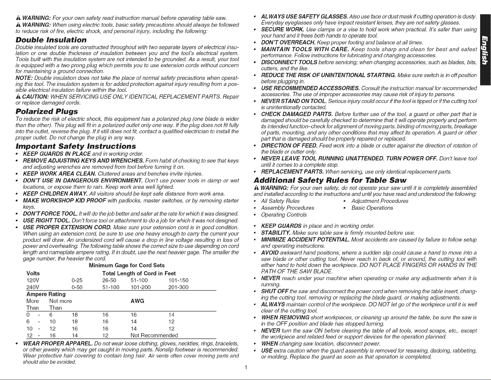
, USE PROPER EXTENSION CORD. Make sure your extension cord is in good condition.
When using an extension cord, be sure to use one heavy enough to carry the current your
product will draw. An undersized cord will cause a drop in line voltage resulting in loss of
power and overheating. The following table shows the correct size to use depending on cord
length and nameplate ampere rating. If indoubt, use the next heavier gage. The smaller the
gage number, the heavier the cord.
Minimum Gage for Cord Sets
Volts Total Length of Cord in Feet
120V 0-25 26-50 51-100 101-150
240V 0-50 51-100 101-200 201-300
Ampere Rating
More Not more AWG
Than Than
0 6 18 16 16 14
6 10 18 16 14 12
10 12 16 16 14 12
12 16 14 12 Not Recommended
WEAR PROPER APPAREL. Do not wear loose clothing, gloves, neckties, rings, bracelets,
or other jewelry which may get caught in moving parts. IVonslip footwear is recommended.
Wear protective hair covering to contain long hair. Air vents often cover moving parts and
should also beavoided.
, AL WAYS USE SAFETY GLASSES. Also use face ordust mask ffcutting operation isdusty.
Everyday eyeglasses only have impact resistant lenses, they are not safety glasses.
, SECURE WORK. Use clamps or a vise to hold work when practical It's safer than using
your hand and it frees both hands to operate tool.
, DON'T OVERREACH. Keep proper footing and balance at all times.
, MAINTAIN TOOLS WITH CARE. Keep tools sharp and clean for best and safest
performance. Follow instructions for lubricating and changing accessories.
, DISCONNECT TOOLS before servicing; when changing accessories, such as blades, bits,
cutters, and the like.
, REDUCE THE RISK OF UNINTENTIONAL STARTING. Make sure switch is in off position
before plugging in.
, USERECOMMENDEDACCESSORIES. Consulttheinstructionmanualforrecommended
accessories. The use of improper accessories may cause risk of injury to persons.
, NEVER STAND ON TOOL. Serious injury could occur ff the tool is tipped or ff the cutting tool
is unintentionally contacted.
, CHECK DAMAGED PARTS. Before further use of the tool, a guard or other part that is
damaged should be carefully checked to determine that it will operate properly and perform
its intended function-check for alignment of moving parts, binding of moving parts, breakage
of parts, mounting, and any other conditions that may affect its operation. A guard or other
part that is damaged should be properly repaired or replaced.
, DIRECTION OF FEED. Feed work into a blade or cutter against the direction of rotation of
the blade or cutter only.
, NEVER LEAVE TOOL RUNNING UNATTENDED. TURN POWER OFF. Don't leave tool
until it comes to a complete stop.
, REPLACEMENT PARTS. When servicing, use only identical replacement parts.
Additiena# Safety Ru#es for Tab#e Saw
,_, WARNING: For your own safety, do not operate your saw until it is completely assembled
and installed according to the instructions and until you have read and understood the following:
* All Safety Rules * Adjustment Procedures
* Assembly Procedures * Basic Operations
* Operating Controls
• KEEP GUARDS in place and in working order.
• STABILITY. Make sure table saw is firmly mounted before use.
• MINIMIZE ACCIDENT POTENTIAL. Most accidents are caused by failure to follow setup
and operating instructions.
• AVOID awkward handpositions, where a sudden slip could cause a hand to move into a
saw blade or other cutting tool. Never reach in back of, or around, the cutting tool with
either hand to hold down the workpiece. DO NOT PLACE FINGERS OR HANDS IN THE
PATH OF THE SAW BLADE.
• NEVER reach under your machine when operating or make any adjustments when it is
running.
• SHUT OFF the saw and disconnect the power cord when removing the table insert, chang-
ing the cutting tool, removing or replacing the blade guard, or making adjustments.
• AL WAYS maintain control of the workpiece. DO NOT let go of the workpiece until it is well
clear of the cutting tool
• WHEN REMOVING short workpieces, or cleaning up around the table, be sure the saw is
in the OFF position and blade has stopped turning.
• NEVER turn the saw ON before clearing the table of all tools, wood scraps, etc., except
the workpiece and related feed or support devices for the operation planned.
• WHEN changing saw location, disconnect power.
• USE extra caution when the guard assembly is removed for resawing, dadoing, rabbeting,
or molding. Replace the guard as soon as that operation is completed.
Page 4
* NEVERholdontoortouchthe'_reeend"oftheworkpiece
ora'_reepiece"thatiscutoff,whilepowerisONand/or
thesawbladeisrotating.
* IF YOU STALL OR JAM the saw blade in the workpiece,
tum saw OFF, remove the workpiece from the saw blade,
and check to see ff the saw blade is parallel to the miter
gauge slots or grooves and if the splitter is in proper
alignment with the saw blade. If ripping at the time, check
to see ff the rip fence is paraflel with the saw blade.
Readjust as indicated.
_ WARNING: Do not allow familiarity (gained from frequent
use of your saw) to replace following safety rules. Always
remember that a careless fraction of a second is sufficient
to inflict severe injury.
* MAKE SURE your fingers do not contact the terminals of
the power cord when installing or removing the plug to or
from the line power source.
* KICKBACKS - Kickbacks can cause serious injury. A
kickback occurs when a part of the workpiece binds
between the saw blade and the rip fence, or other fixed
object, and rises from the table and is thrown toward the
operator. Kickbacks can be avoided by attention to the
following conditions:
KICKBACKS--HOW TO AVOID THEM AND
PROTECT YOURSELF FROM POSSIBLE INJURY.
a) Be certain that the saw blade is parallel to the rip fence.
Adjust fence ff not parallel
b) Do not rip by applying the feed force to the section of the
workpiece that will become the cut-off (free) piece. Feed
force when ripping should always be applied between
the saw blade and the fence.., use apush stick for short
work, 6" (152mm) wide or less. For less than 2" (51mm)
wide, you must use a special fixture.
c) Keep saw blade guard, spfitter and anti-kickback teeth
in place and operating properly. Keep teeth sharp, ff
teeth are not operational, return your unit to the
nearest DEWAL T Service Center for repair. The
spfitter must be in alignment with the saw blade and the
teeth must stop a kickback once it has started. Check
their action before ripping by pushing the wood under
the anti-kickback teeth. The teeth must prevent the
wood from being pulled toward the front of the saw.
d) Plastic and composition (like hardboard) materials may
be cut on your saw. However, since these are usually
quite hard and slippery, the anti-kickback teeth may not
stop a kickback. Therefore, be especially attentive to
following proper set up and cutting procedures for
ripping.
e) Use saw blade guard and spfitter for every operation for
which it can be used, including all through sawing.
* DO NOT leave a long board (or other workpiece)
unsupported so the spring of the board causes it to shift on
the table. Provide proper support for the workpiece, based
on its size and the type of operation to be performed. Hold
the work firmly against the fence and down against the
table surface.
• NEVER use a length stop on the free endofthe workpiece
when crosscutting. Never hang onto or touch the free end
of the workpiece when crosscutting, or a free piece that is
cut off when ripping while power is ON and/or the saw
blade is rotating. In short, the cut-off piece in any 'thru-
sawing" (cutting completely through the workpiece)
operation must never be confined -- it must be allowed to
move away from saw blade.
• IF YOUR SAW makes an unfamiliar noise or ff it vibrates
excessively, cease operating immediately until the source
has been located and the problem corrected.
• KEEP OUT of the fine of saw blade. Stand to the side
whene vet possible.
• USE a push-stick when required. (See page 9)
• PAYparticular attention to instructions on reducing risk of
kickback.
• DO NOTperform any operation free hand.
• NEVER reach around, behind or over saw blade.
• USE RECOMMENDED ACCESSORIES. The use of
improper accessories may cause risk of personal injury.
i_,WARNING: Some dust created by power sanding, saw-
ing, grinding, drilling, and other construction activities con-
tains chemicals known to cause cancer, birth defects or
other reproductive harm. Some examples of these chemi-
cals are:
• lead from lead-based paints,
• crystalline silica from bricks and cement and other
masonry products, and
• arsenic and chromium from chemically-treated lum-
ber (CCA).
Your risk from these exposures varies, depending on how
often you do this type of work. To reduce your exposure to
these chemicals: work in a well ventilated area, and work
with approved safety equipment, such as those dust masks
that are specially designed to filter out microscopic particles.
• Avoidprolonged contact with dust from power sand-
ing, sawing, grinding, drilling, and other construc-
tion activities. Wear protective clothing and wash
exposed areas with soap and water. Allowing dust to
get into your mouth, eyes, or lay on the skin may promote
absorption of harmful chemicals.
_ WARNING: Use of this tool can generate and/or disburse
dust, which may cause serious and permanent respiratory
or other injury. Always use NIOSH/OSHA approved respira-
tory protection appropriate for the dust exposure. Direct par-
ticles away from face and body.
i_, CA UTION: Wear appropriate hearing protection dur-
ing use. Under some conditions and duration of use, noise
from this product may contribute to hearing loss.
SAVE THESE INSTRUCTIONS FOR
FUTURE USE
FIG. 1
FIG. 2
4_
6
Page 5

FIG. 3
SCREW-DOWN
HOLES
FIG. 4
WORK SUPPORT
EXTENSION
(RETRACTED)
GAUGE
MOUNTING
BLADE GUARD
ON-OFF SWITCH
RIP SCALE INDICATOR
FINE ADJUST
BLADE HEIGHT
BEVEL LOCK
LEVER
ANTI-KICKBACK TEETH
RAIL LOCK
LEVER
KNOB
ADJUSTMENT
WHEEL
RIP FENCE
LATCH
Specifications
Horsepower 2-1/2
Table Size 19 1/4" x 26 1/2"
Miter Angle 30° L&R
Bevel Angle 0° to 45°L
Blade Size 10" (254mm)
Max. Cut Depth 0° Bevel ................ 3 1/8" (79ram)
Max. Cut Depth 45° Bevel ..............2-1/4" (57mm)
RPM, no load 3650
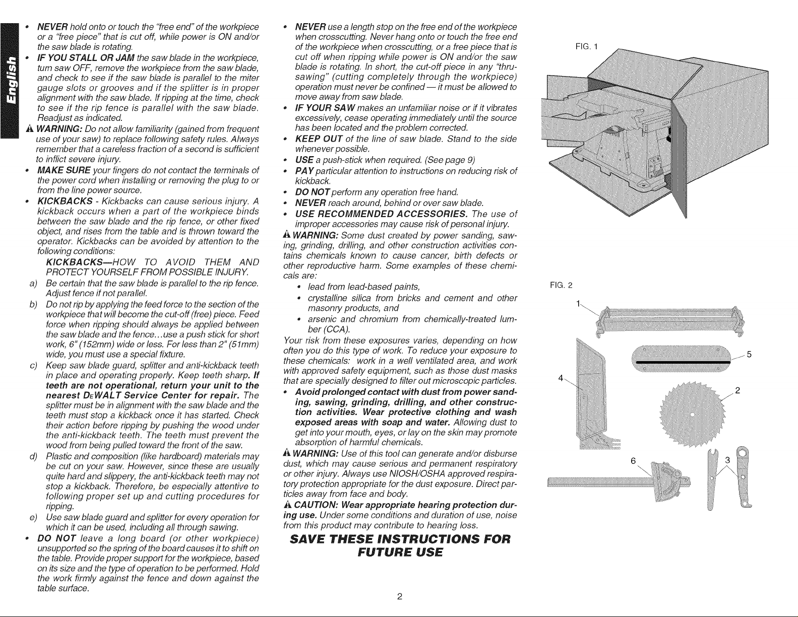
Unpacking
Open the box and slide the saw out, as shown in Figure 1.
Carefully unpack the table saw and all loose items from the
carton. Examine all parts to make sure that parts have not
been damaged during shipping. If any parts are missing or
damaged, contact your dealer to replace them before
attempting to assemble the tool.
Figure 2 shows all the loose items and hardware packed with
the saw.
1. Rip fence
2. Blade (attached to saw base)
3. Arbor wrench and spindle wrench (attached to saw
base)
4. Blade guard
5. Throat plate
6. Miter gauge
Examine Figures 3 & 4 to become familiar with the saw and
its various parts. The following sections on assembly and
adjustments will refer to these terms and you must know
what and where the parts are.
Assembly
YOUR SAW SHOULD BE ASSEMBLED IN THE
FOLLOWING ORDER:
1. Blade
2. Rip fence (NOTE: Adjust rip scale before proceeding.
See "Adjusting Rip Scale".)
3. Blade guard
4. Throat plate
FIG. 5
PIN
BLADE/WRENCH
STORAGE
OPENING
DUST EXHAUST
Page 6

Tools needed for assembly include a screwdriver and the
wrenches included with your saw.
ASSEMBLING THE RIP FENCE
The rip fence can be installed on the left or right side of your
table saw.
1. Locate the pin and opening on fence rails, as shown in
Figure 5. Align the pin with the slot and align the latch
with the opening.
2. Secure the rip fence by snapping the latches onto the
rails as shown in Figure 6. Be sure to snap both latches
in place.
ATTACHING/REPLACING THE BLADE
1. Raise the saw blade arbor to its maximum height by
turning the blade height adjustment wheel clockwise.
2. Remove the arbor nut and flange from the saw arbor by
turning counterclockwise.
3. Place the saw blade on to the spindle making sure the
teeth of the blade point down at the front of the table.
Assemble the washers and arbor nut to the spindle and
tighten arbor nut as far as possible by hand, making
sure that the saw blade is against the inner washer and
the large washer diameters are against the blade.
Ensure the side of outer washer marked "Blade Side" is
against the blade (see Figure 7). Ensure the spindle and
washers are free from dust and debris.
4. To keep the spindle from rotating when tightening the
arbor nut, use the open-ended spindle wrench to secure
the spindle (see Figure 8).
5. Using the arbor wrench, tighten the arbor nut by turn-
ing it clockwise (see Figure 8).
6. NOTE: Different types of blades make different kerfs
(width of cuts). Therefore, it is necessary to check
adjustment of rip fence pointer and blade guard splitter
when changing blades.
ADJUSTING THE RIP SCALE
1. Unlock the rail lock lever (see Figure 9).
2. Set the blade at 0° bevel and move the fence in until it
touches the blade.
3. Lock the rail lock lever.
4. Loosen the rip scale pointer screws (see Figure 16) and
set the rip scale pointer to read zero (0). Retighten the
rip scale pointer screws. The rip scale reads correctly
only when the fence is mounted on the right side of the
blade.
ATTACHING THE BLADE GUARD
1. Raise the saw blade arbor to its maximum height by
turning the blade height adjustment wheel clockwise.
2. Loosen, but do not remove the two bolts shown in
Figure 10.
3. Insert the blade guard as shown in Figure 11, ensuring
the bolts fit into the slots on the blade guard. The edge
of the splitter should protrude below and hook under the
shims. Tighten the bolts. Make sure the splitter is cen-
tered and parallel to the blade by lining up the parts with
a straight edge. If the blade and splitter are not aligned,
loosen, but do not remove the bolts again. Remove the
guard and reinsert it after adjusting the shims. These
shims allow for precision alignment of the blade and
splitter. Tighten the bolts securely. Make sure that there
is clearance between the splitter and the blade, and
that the blade spins freely. If the splitter is tilted relative
to the blade, the splitter plate can be bent until it lines
up correctly.
IMPORTANT: THE GUARD SHOULD BE IN PLACE
FOR ALL POSSIBLE CUTS.
4. Retighten the bolts securely.
_ WARNING: Before connecting the table saw to the power
source or operating the saw, always inspect the guard and
spfitter for proper alignment and clearance with saw blade.
Check alignment after each change of bevel angle.
When properly aligned, the splitter will be in line with the
blade at both table top level, and at the top of the blade.
Check using the straight edge. With power disconnected,
operate the blade tilt and height adjustments through the
extremes of travel and insure the guard clears the blade in all
operations and that the anti-kickback teeth are functioning.
ATTACHING THE THROAT PLATE
1. Align the throat plate as shown in Figure 12, and insert
the tabs on the back of the throat plate into the holes on
the back of the table.
2. Press down on the front of the throat plate to snap it into
place.
3. The throat plate includes four adjustment screws which
raise or lower the throat plate. When properly adjusted,
the front of the throat plate should be flush or slightly
below the surface of the table top and secured in place.
The rear of the throat plate should be flush or slightly
above the table top.
4. Turn the cam lock screw (Detail Fig. 12) clockwise 1/4
turn to lock the throat plate in place.
i_, CAUTION: The throat plate must be in place at all times.
Bench Mounting
TURN OFF AND UNPLUG TABLE SAW
The table saw must be mounted firmly. The mounting sup
face must have a 15" by 20" opening to allow dust to
escape.
Four holes are provided in the tool's feet for mounting. We
strongly recommend that these holes be used to anchor the
table saw to your workbench or other stationary rigid frame.
Alternately, to enhance the saw's portability, it can be
mounted to a piece of wood that can be "C" clamped to your
work surface, stand or Workmate® Workcenter. The
DEWALT DW7440 Table Saw Stand is designed for use with
this saw, and is available from your local DEWALT dealer or
service center.
FIG. 7A
FIG. 6
iNNER
WASHER
BLADE
REAR PINION BEARING ASSEMBLY
(SAW SHOWN UPSIDE DOWN FOR CLARITY)
OUTER
WASHER
ARBOR
NUT
Page 7
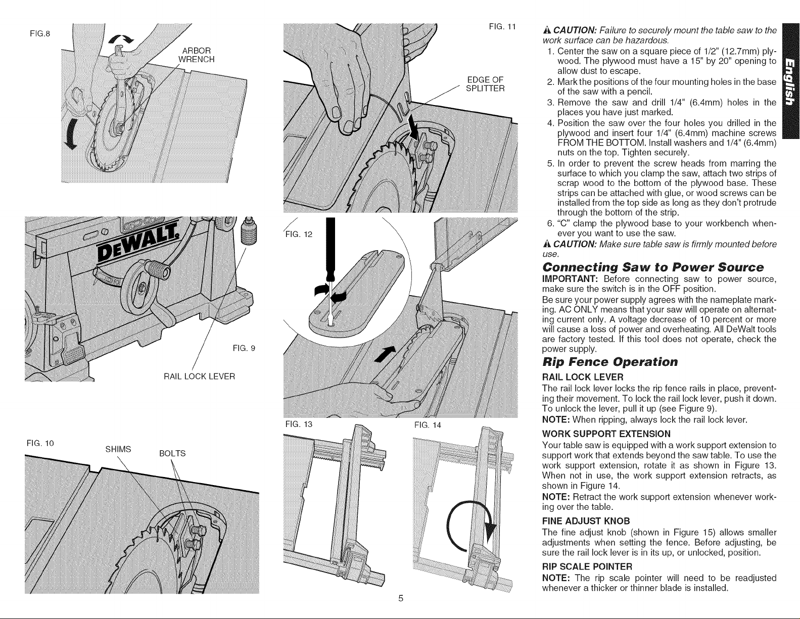
FIG.8
FIG.10
SHIMS
ARBOR
WRENCH
FIG.9
RAILLOCKLEVER
BOLTS
FIG.13
FIG.14
FIG.11
EDGEOF
SPLITTER
_ CAUTION: Failure to securely mount the table saw to the
work surface can be hazardous.
1. Center the saw on a square piece of 1/2" (12.7mm) ply-
wood. The plywood must have a 15" by 20" opening to
allow dust to escape.
2. Mark the positions of the four mounting holes in the base
of the saw with a pencil.
3. Remove the saw and drill 1/4" (6.4mm) holes in the
places you have just marked.
4. Position the saw over the four holes you drilled in the
plywood and insert four 1/4" (6.4mm) machine screws
FROM THE BOTTOM. Install washers and 1/4" (6.4mm)
nuts on the top. Tighten securely.
5. In order to prevent the screw heads from marring the
surface to which you clamp the saw, attach two strips of
scrap wood to the bottom of the plywood base. These
strips can be attached with glue, or wood screws can be
installed from the top side as long as they don't protrude
through the bottom of the strip.
6. "C" clamp the plywood base to your workbench when-
ever you want to use the saw.
CAUTION: Make sure table saw is firmly mounted before
use.
Connecting Saw to Power Source
IMPORTANT: Before connecting saw to power source,
make sure the switch is inthe OFF position.
Be sure your power supply agrees with the nameplate mark-
ing. AC ONLY means that your saw will operate on alternat-
ing current only. A voltage decrease of 10 percent or more
will cause a loss of power and overheating. All DeWalt tools
are factory tested. If this tool does not operate, check the
power supply.
Rip Fence Operation
RAIL LOCK LEVER
The rail lock lever locks the rip fence rails in place, prevent-
ing their movement. To lock the rail lock lever, push it down.
To unlock the lever, pull it up (see Figure 9).
NOTE: When ripping, always lock the rail lock lever.
WORK SUPPORT EXTENSION
Your table saw is equipped with a work support extension to
support work that extends beyond the saw table. To use the
work support extension, rotate it as shown in Figure 13.
When not in use, the work support extension retracts, as
shown in Figure 14.
NOTE: Retract the work support extension whenever work-
ing over the table.
FINE ADJUST KNOB
The fine adjust knob (shown in Figure 15) allows smaller
adjustments when setting the fence. Before adjusting, be
sure the rail lock lever is in its up, or unlocked, position.
RIP SCALE POINTER
NOTE: The rip scale pointer will need to be readjusted
whenever a thicker or thinner blade is installed.
Page 8

On-Off Switch
Lift the switch paddle up to turn your saw ON and push it
down to turn your saw OFF.
A hole is provided in the switch for insertion of a padlock to
lock the saw off (Figure 17).
_ WARNING: Be sure switch is in the OFF position before
plugging machine in.
Adjustments
NOTE: Your saw is fully and accurately adjusted at the fac-
tory at the time of manufacture. If readjustment due to ship-
ping and handling or any other reason is required, follow the
steps below to adjust your saw.
Once made, these adjustments should remain accurate.
Take a little time now to follow these directions carefully to
maintain the accuracy of which your saw is capable.
RAiL LOCK ADJUSTMENT
1. Lock the rail lock lever (Figure 9) by pushing down.
2. On the underside of your saw, tighten the nut shown in
Figure 18. Adjust this nut until the gap between the
belleville washers closes.
3. Once the springs are almost touching, tighten the nut
1/2 turn.
RIP SCALE ADJUSTMENT
See "ADJUSTING THE RIP SCALE" on page 4.
ADJUST BLADE ALIGNMENT TO TABLE
1. THE SAW MUST BE UNPLUGGED BEFORE YOU
MAKE ANY ADJUSTMENT TO THE BLADE.
2. Place the unit in an upright position. Using a 10ram
socket, loosen rear pivot bracket fasteners just enough
to allow the bracket to move side-to-side.(Figure 7A).
3. Adjust the bracket until the blade is parallel to the miter
gauge slot.
4. Tighten the rear pivot bracket fasteners to 7-8 ft.lbs.
BEVEL STOP AND POINTER ADJUSTMENT
1. Raise the blade fully by rotating the blade height adjust-
ment wheel clockwise until it stops.
2. Unlock the bevel lock lever (Figure 3) by pushing it up
and to the right. Loosen the bevel stop screw
(Figure 19).
3. Place a square flat against the table top and against the
blade between teeth, as shown in Figure 20. Ensure the
bevel lock lever is in its unlocked, or up, position.
4. Using the bevel lock lever, adjust the bevel angle until it
is flat against the square.
5. Tighten the bevel lock lever by pushing it down.
6. Turn the bevel stop cam until it firmly contacts the bear-
ing block. Tighten the bevel stop screw.
7. Check the bevel angle scale. If the pointer does not read
0°, loosen pointer screw (see Figure 19) and move the
pointer so it reads correctly. Retighten the pointer screw.
8. Repeat at 45°, but do not adjust pointer.
MITER GAUGE ADJUSTMENT
Your miter gauge features adjustable stops at 90° and 45°
left and right. To adjust these stops, loosen the lock nuts and
tighten or loosen the three adjusting screws against the stop
plate (see Figure 21).
FENCE PARALLEL ADJUSTMENT
1. Unlock rail lock lever.
2. Locate rear pinion bearing and loosen the two hex bolts
just enough to allow side-to-side movement.
3. Adjust fence parallel to blade.
4. Lock rail lock lever and check parallel alignment of the
blade.
5. Tighten the 2 hex bolts that secure the rear pinion bear-
ing assembly to the table.
NOTE: If there is not enough travel in the pinion bearing
assembly to allow the fence to be parallel to the blade,
take the unit to an authorized service center.
RACK AND PINION MESH ADJUSTMENT
Proper adjustment of the rack and pinion mesh is done at
the factory. If it should become necessary to adjust the rack
and pinion mesh, use the following procedure.
1. Turn the saw upside down and locate the front pinion
bearing.
2. Using a narrow blade screw driver or #20 torx driver,
access the screw through the slot. Loosen the screw
(counterclockwise) until the head touches the inside of
the bearing box.
3. Tighten the screw (clockwise) 3/4 of a turn.
4. Repeat procedure for rear pinion bearing.
Saw Blades
THIS SAW IS INTENDED FOR THE USE OF SAW
BLADES 10" IN DIAMETER OR SMALLER
1. The saw blade furnished with your new saw is a 10"
(254mm) combination blade, used for cross cutting
(across the grain) and ripping (with the grain) through
the material. The center hole to fit on the arbor is 5/8"
(16mm) diameter (.625"). This blade will produce a good
quality cut for most applications.
2. There are many types of blades available to do specific
and special jobs such as cross cut only, rip only, hollow
ground, thin plywood, paneling, etc.
3. Use only saw blades designed for maximum safe oper-
ating speeds of 5,000 RPM or greater.
4. Saw blades should always be kept sharp. It is recom-
mended that you locate a reputable sharpening service
to sharpen your blades when needed.
5. Never stack blades on top of one another to store. Place
material such as cardboard between them to keep the
blades from coming in contact with one another.
i_, CAUTION: Abrasive wheels should not be used on this
saw.
FINE ADJUST KNOB
SCREWS
FIG. 16
PADLOCK
INSERTION
HOLE
ON-OFF
SWITCH
FIG. 17
Page 9

FIG.18
FIG.19
FIG.20
BEVELSTOP
SCREW
BELVILLE
WASHERS
STOP CAM
POINTER
SCREW
I GAP
i
BEVEL
FIG. 21
STOP PLATE
PUSH STICK
LOCK HANDLE
ADJUSTING
SCREW
NUT
FIG. 22
FIG. 23
Kickback
Kickback is a dangerous condition! It is caused by the work-
piece binding against the blade. The result is that the work-
piece can move rapidly in a direction opposite to the feed
direction. During kickback, the workpiece could be thrown
back at the operator. It can also drag the operator's hand
back into the blade if the operator's hand is at the rear of the
blade. If kickback occurs, turn the saw OFF and verify the
proper functioning of the splitter, anti-kickback teeth and
guards before resuming work.
CA UTION:
1.Always use the guard and make certain it is in good
working order. The guard's spfitter helps prevent binding
and the anti-kickback teeth on each side of the spfitter
minimize the possibility of kickback. Use extra caution
until the workpiece is through the spfitter and has
engaged anti-kickback teeth.
2. Do not saw warped, bowed or cupped wood. The work-
piece must have one straight, smooth side to go against
the rip fence or miter gauge. The workpiece must sit flat
on the table without rocking.
3. Do not cut '_reehand" Always use either the rip fence or
the miter gauge. Never use both.
4. Use extra care when the guard assembly cannot be
used (during dadoing or molding).
5. Support large workpieces carefully. Allowing them to
sag or droop can cause kickback.
Operation
Plain sawing includes ripping and cross cutting, plus a few
other standard operations of fundamental nature. The fol-
lowing methods feature safety. As with all power tools
respecting the tool, using caution and following safe prac-
tices will considerably lessen the possibility of personal
injury. However, if normal safety precautions are overlooked
or completely ignored, personal injury to the operator can
result. Read and follow all warnings indicated on the saw.
Through sawing is any operation which renders the materi-
al into two separate pieces.Observe the safety rules includ-
ed in this manual.
THIS SAW IS NOT INTENDED FOR CUTTING METAL.
Operating Instructions
There are two basic types of cuts: ripping and crosscutting.
In general, cutting with the grain is ripping and across the
grain is crosscutting. However, with man made materials
this distinction is somewhat difficult to make. Therefore, cut-
ting a piece of wood to a different width is ripping and cut-
ting across the short dimension is crosscutting. Neither rip-
ping or crosscutting may be done safely freehand! Ripping
requires the use of the rip fence and crosscutting uses the
miter gauge.
_J,CAUTION: Before using the saw each and every time
verify the following:
1. Blade is tight.
2. Bevel angle lock knob is tight.
Page 10

3.Ifripping,ensureraillockleveristightandfenceispar-
alleltotheblade.
4.Ifcrosscutting,mitergaugeleveristight.
5.Guardisinplaceandworkingproperly.
6.Safetyglassesarebeingworn.
7.Thebladeguardisproperlyattachedandtheanti-kick-
backteetharefunctioning.
Failuretoadheretothesecommonsafetyrulescangreatly
increasethelikelihoodofinjury.
Ripping
1. Lock the rip fence by pressing the rail lock lever down,
Remove the miter gauge.
2. Raise the blade so it is about 1/8"(3.2mm) higher than
the top of the workpiece.
3. Hold the workpiece flat on the table and against the
fence. Keep the workpiece about 1" (25.4mm) away
from the blade.
,& CAUTION: The workpiece must have a straight edge
against the fence and must not be warped, twisted or
bowed. Keep both hands away from the blade and away
from the path of the blade.
4. Turn the saw on and allow the blade to come up to
speed. Both hands can be used in starting the cut.
When there is approximately twelve (12) inches
(305mm) left to be ripped...use only one hand, with your
thumb pushing the material, your index and second fin-
ger holding the material down and your other fingers
hooked over the fence. Always keep your thumb along
side your first two fingers and near the fence.
5. Keeping the workpiece against the table and fence,
slowly feed the workpiece rearward all the way through
the saw blade. Continue pushing the workpiece until it is
clear of the guard and it falls off the rear of the table. Do
not overload the motor.
6. Never try to pull the workpiece back with the blade turn-
ing. Turn the switch off, allow the blade to stop, raise the
anti-kickback teeth on each side of the splitter if neces-
sary and slide the workpiece out.
7. When sawing a long piece of material or a panel, always
use a work support. A sawhorse, rollers, or out feed
assembly provides adequate support for this purpose. The
work support must be at the same height as the saw
table.
A CAUTION: Never push or hold onto the '_ree" or "cut off"
side of the workpiece.
Bevel Ripping
This operation is the same as ripping except the bevel angle
is set to an angle other than zero degrees.
,_ WARNING: Before connecting the table saw to the power
soume or operating the saw, always inspect the guard and
spfitter for proper alignment and clearance with saw blade.
Check alignment after each change of bevel angle.
Ripping Small Pieces
It is unsafe to rip small pieces. It is not safe to put your hands
close to the blade. Instead, rip a larger piece to obtain the
desired piece. When a small width is to be ripped and the
hand cannot be safely put between the blade and the rip
fence, use one or more push sticks. A pattern is included on
page 9 to make push sticks. Use them to hold the workpiece
against the table and fence, and push the workpiece fully
past the blade. See Figure 22.
Crosscutting
1. Remove the rip fence and place the miter gauge in the
desired slot.
2. Adjust the blade height so that the blade is about 1/8"
(3.2ram) higher than the top of the workpiece.
3. Hold the workpiece firmly against the miter gauge with
the path of the blade in line with the desired cut location.
Keep the workpiece an inch or so in front of the blade.
KEEP BOTH HANDS AWAY FROM THE BLADE AND
THE PATH OF THE BLADE.
4. Start the saw motor and allow the blade to come up to
speed.
5. While using both hands to keep the workpiece against
the face of the miter gauge, and holding the workpiece
flat against the table, slowly push the workpiece through
the blade. See Figure 23.
6. Never try to pull the workpiece with the blade turning.
Turn the switch off, allow the blade to stop, and carefully
slide the workpiece out.
i_ CAUTION: Never touch or hold onto the "free" or "cut off"
end of the workpiece.
Bevel Crosscutting
This operation is the same as crosscutting except that the
bevel angle is set to an angle other than 0°.
_ WARNING: Before connecting the table saw to the power
source or operating the saw, always inspect the guard and
splitter for proper alignment and clearance with saw blade.
Check alignment after each change of bevel angle.
Mitering
This operation is the same as crosscutting except the miter
gauge is locked at an angle other than 0°. Hold the work-
piece FIRMLY against the miter gauge and feed the work-
piece slowly into the blade (to prevent the workpiece from
moving). See Figure 23.
MITER GAUGE OPERATION
To set your miter gauge, loosen the lock handle and move
the miter gauge to the desired angle. The miter gauge has
set stops and 90 ° and 45° left and right. To rotate the miter
gauge beyond these stops, flip the stop plate up, as shown
in Figure 21.
Compound Mitering
This is a combination of bevel crosscutting and mitering.
Follow the instruction for both bevel crosscutting and
mitering.
8
FIG. 24
DUST ACCESS
DOOR
HAIR PIN COTTERS
FIG. 25
HEIGHT
ADJUSTMENT
THREADS
Dado Cutting
A CAUTION: Do not attempt to stack dado blades thicker
than 13/16" (20mm). Do not use dado blades larger than 8"
(200mm) diameter. When installing the dado stack, do not
include the inner clamp washer. Replace it with the outer
clamp washer, then install the blade stack, arbor nut, and
tighten with the wrench supplied.
Since dado cuts are not through cuts, the cuts must be per-
formed with the blade guard removed. To remove the blade
guard, loosen the two bolts shown in Figure 10 and remove
the guard assembly.
When using the dado, the special dado insert (also sold as
an accessory) must be used.
Anytime a cut is required that is considerably wider than the
saw ken', a dado is used. A dado cut is commonly used to
add support and line up a shelf for a cabinet, bookcase or
some such project. When using the dado, the guard must be
removed. Use EXTREME care when using the dado without
the guard. If a deep cut is required. Use several successive
Page 11

passesratherthanattemptingtomakeitwithonepass.
Maximumdadowidthonthissawis13/16"(20mm).DO
NOTUSEWIDERCOMBINATIONS.
,_ CAUTION: Always check dado blade clearance before
plugging in the saw.
Be sure to place the guard and standard throat plate back in
position and check adjustments when the dado cuts are
complete.
Dust Collection
Your table saw is equipped with a dust shroud and dust col-
lection port. For best results, connect a vacuum to the port
at the rear of the saw.
If the saw is operated without a vacuum attached, most of
the dust will be blown out the dust collection port. However,
some dust will fall inside the base. If the saw is used on a
table or other surface without an opening on the bottom,
clean out the base and accumulated saw dust after each
cut.
After extended use, the saw's dust collection system may
become clogged. To clear the dust collection system:
a) Unplug the saw.
b) Turn the saw on its side, so the bottom, open part of the
unit is accessible.
c) Open the dust access door shown in Figure 24 by
removing the two hair pin cotters shown. Clean out the
excess dust, and re-secure the access door with the hair
pin cotters.
When cutting wet wood without a vacuum or when cutting
with a dado blade, removing the dust access door may be
helpful in preventing clogs.
Lubricatiore
1. All motor bearings are permanently lubricated at the fac-
tory and no additional lubrication is needed.
2. The height adjustment screw may require periodic
cleaning and lubrication. If you have difficulty raising or
lowering the blade:
a) Unplug the saw.
b) Turn the saw on its side, so the bottom, open part of
the unit is accessible.
c) Clean and lubricate the height adjustment screws
threads on the underside of your saw with general
purpose grease, shown in Figure 25.
Accessories
Recommended accessories for use with your tool are avail-
able at extra cost from your distributor or local service center.
DEWALT manufactures the following accessories for your
saw:
Portable Saw Stand
Outfeed Side Support
Replacement Throat Plate
Dado Throat Plate
_ CAUTION: The use of any non-recommended accesso-
ry may be hazardous.
If you need assistance in locating any accessory, please
contact DEWALT Industrial Tool Co., 701 East Joppa Road,
Baltimore, MD 21286 or call 1-800-4-DEWALT (1-800-433-
9258).
Cleaning
Use only mild soap and damp cloth to clean the tool. Never let
any liquid get inside the tool; never immerse any part of the tool
into a liquid. Never use solvents to clean saw or guard
components.
Important
To assure product SAFETY and RELIABILITY, repairs,
maintenance and adjustment (including brush inspection
and replacement) should be performed by authorized ser-
vice centers or other qualified service organizations, always
using identical replacement parts.
Three Year Limited Warranty
DEWALT will repair, without charge, any defects due to
faulty materials or workmanship for three years from the
date of purchase. This warranty does not cover part failure
due to normal wear or tool abuse. For further detail of war-
ranty coverage and warranty repair information, visit
www.dewalt.com or call 1-800-4-DEWALT (1-800-433-
9258). This warranty does not apply to accessories or dam-
age caused where repairs have been made or attempted by
others. This warranty gives you specific legal rights and you
may have other rights which vary in certain states or
provinces.
In addition to the warranty, DEWALT tools are covered by
our:
1 YEAR FREE SERVICE
DEWALT will maintain the tool and replace worn parts
caused by normal use, for free, any time during the first year
after purchase.
90 DAY MONEY BACK GUARANTEE
If you are not completely satisfied with the performance of
your DEWALT Power Tool, Laser, or Nailer for any reason,
you can return it within 90 days from the date of purchase
with a receipt for a full refund - no questions asked.
FREE WARNING LABEL REPLACEMENT: If your warning
labels become illegible or are missing, call 1-800-4-DEWALT
for a free replacement.
Page 12

i_,AVERTISSEMENT:PARMESUREDESECURITEPERSONNELLE,LIRELEGUIDED'UTILISATIONAVANTD'UTILISERLASCIE.TOUJOURSPORTERDESLUNETTESDESt_CU-
RIT¢:.NEPASPORTERDEGANTS,DECRAVATE,DEBIJOUXNIDEVETEMENTSAMPLES.PROT¢:GERLACHEVELURELORSQU'ELLEESTLONGUE.€:LOIGNER LES DOIGTS ET
LES MAINS DE LA TRAJECTOIRE DE LA LAME; PRENDRE PARTICULIEREMENT SOIN LORS DES COUPES EN BISEAU. TOUJOURS UTILISER LE PROTECTEUR ET LE Rt_PARTI -
TEUR POUR TOUTES LES COUPES, Y COMPRIS LES COUPES COMPLETES. UTILISER UN BATON POUR POUSSER LE MATERIAU LE CAS ECHCANT. SAVOIR COMMENT ¢:VITER
LES REBONDS; CONSULTER LE GUIDE. TOUJOURS SOUTENIR LA PIECE _, DE_COUPER b, L'AIDE DE LA TABLE ET DU GUIDE, OU DE L'INDICATEUR D'ONGLETS. NE JAMAIS
UTILISER SIMULTANEMENT LE GUIDE ET L'INDICATEUR D'ONGLETS. NE JAMAIS S'¢:TIRER AU-DESSUS NI AUTOUR DE LA LAME. BIEN FIXER LA LAME AVANT D'UTILISER
L'OUTIL NE JAMAIS RETIRER DES PIECES COINCC:ES NI COUPI_ES AVANT D'AVOIR MIS L'OUTIL HORS TENSION ET DE S'ETRE ASSURE DE L'IMMOBILISATION DE LA LAME.
PROTt_GER DE LA PLUIE ET NE PAS UTILISER DANS DES ENDROITS HUMIDES. BIEN FIXER L'OUTIL AFIN D'EN ¢:VITER DES MOUVEMENTS IMPREVUS. NE PAS SE SERVIR DE
L'OUTIL APRES AVOIR CONSOMMI 2 DE L'ALCOOL OU DES DROGUES. LE NON-RESPECT DU PRt_SENT AVERTISSEMENT COMPORTE DES RISQUES DE BLESSURES GRAVES.
D_WALT... CON_U POUR LE CHANTIER
Les outils industriels _ rendement _lev6 DEWALT r_pondent aux pires
exigences de I'industrie et de la construction en Am_rique du Nord. La
conception de chacun des outils de la gamme (des perceuses aux pon-
ceuses, en passant par les rectifieuses) r6sulte de leur utilisation
rigoureuse sur le chantier et dans I'industrie. Chaque outil est constru-
it avec une pr6cision laborieuse & I'aide de syst_mes de fabrication de
pointe et un intense contr61e de la qualit6. Chacun d'eux est soigneuse-
ment v6rifi6 avant de quitter I'usine afin de s'assurer que I'outil r6pond
aux normes de durabilit6, de fiabilit6 et de puissance des utilisateurs.
DEWALT Con£u pour le chantier ... NOUS LE GARANTISSONS.
10
Page 13

Irnportaretes rnesures de s_curit_ pour tous les outils
i_ P VERTISSEMENT : Afin de r#duire /es risques d'incendie, de secousses #/ectriques ou
de blessures Iorsqu'on utilise des outils #lectriques, il faut toujours respecter les mesures de
s#curit# suivantes.
LIRE TOUTES [ES DIRECTIVES
Pour tous les outils
• S'assurer que les protecteurs sont en place et en bon #taL
, ENLEVER LES CLE':S DE RE:GLAGE. Prendre I'habitude de v#rifier si les cl#s de r#glage
ont #t# retir#es avant de faire d#marrer Ibutil.
, BIEN DE=GAGER LA SURFACE DE TRAVAIL. Des surfaces et des #tablis encombr#s
peuvent #tre la cause de blessures.
, TENIR COMPTE DU MILIEU DE TRA VAIL. Prot#ger les outils #lectriques de la pluie. Ale
pas s'en servir clans des endroits humides ou mouill#s. Bien #clairer la surface de travail
, C=LOIGNER LES ENFANTS. Tousles visiteurs doivent _tre tenus a I'#cart de I'aire de
travail.
, RENDRE L'A TELLER SE:CURITAIRE POUR LES ENFANTS a I'aide de cadenas, de dis-
joncteurs, ou en retirant les cl#s de mise en tension.
, NE JAMAIS FORCER L'OUTIL. Afin d'obtenir un rendement sOr et efficace, utiliser Ibutil
son rendement nominal
, UTILISER L'OUTIL APPROPRIE=. Ale jamais exiger d'un petit outil ou d'un accessoire le
rendement d'un outil de fabrication plus robuste.
, PORTER DES VETEMENTS APPROPRIE=S. E-viterde porter des v#tements amples, des
gants, des colliers, des bagues, des bracelets ou d'autres bijoux qui peuvent #tre happ#s
par les pi#ces en mouvement. Le port des chaussures a semelle antid#rapante est
recommand#. Prot#ger la chevelure si e#e est Iongue.Se tenir #loign# des #vents
puisque ces demiers pourraient camoufler des pi#ces mobiles.
, PORTER DES LUNETTES DE SE:CURITE:. Porter #galement un masque respiratoire si
le travail de coupe produit de la poussi#re. Des lunettes de correction de la vue standard
comportent seulement des verres r#sistant aux chocs; ce NE sont PAS des lunettes de
s#curit#.
, NE PAS Di--,PASSER SA PORTE:E. Toujours demeurer clans une position stable et garder
son #quilibre.
, PRENDRE SOIN DES OUTILS. Conserver les outils propres et affOt#s pour qu'ils donnent
un rendement sup#rieur et sot. Suivre les directives concemant la lubrification et le rem-
placement des accessoires.
, DE.BRANCHER L'OUTIL avant de le r#parer ou d'en changer un accessoire (comme une
lame, un foret ou un couteau).
• minimiser les risques de d#marrages accidentels. S'assurer que I'interrupteur est en posi-
tion hors tension avant de brancher I'outiL
• utiliser les accessoires recommand#s. L'utilisation d'accessoires inappropri#s pr#sente
des risques de blessures.
, NE JAMAIS SE TENIR SUR L'OUTIL. Cela pr#sente des risques de blessures graves si
I'outil bascule ou si on touche a la lame par inadvertance.
, VE:RIFIER LES PI[':CES ENDOMMAGE_=ES. Avant de continuer 9 utiliser I'outil, il faut v#ri-
tier si le protecteur ou toute autre pi#ce endommag#e rempfit bien la fonction pour laque-
lie il a #t# pr#vu. V#rifier I'alignement et les attaches des pi#ces mobiles, le degr# d'usure
des pi#ces et leur montage, ainsi que tout autre facteur susceptible de nuire au bon fonc-
tionnement de I'outil. Ale jamais se servir d'un outil dont I'interrupteur est d#fectueux.
, NE JAMAIS LAISSER UN OUTIL EN MARCHE SANS SURVEILLANCE. LE METTRE
HORS TENSION. Alepas laisser I'outil avant I'immobilisation compl#te de la lame.
, NE PAS UTILISER LES OUTILS PORTA TIFS E':LECTRIQUES DANS DES ENDROITS
O0 L 'ATMOSPHE:RE CONTIENT DES VAPEURS COMBUSTIBLES OU EXPLOSIVES.
Les #tincelles que produ# le moteur en marche pourraient enflammer ces produits.
, DEMEURER VIGILANT. Travailler avec vigilance et faire preuve de bon sens. Ne pas se
servir de I'outil Iorsqubn est fatigu#.
, CORDONS DE RALLONGE PRE:VUS POUR L'EXTE:RIEUR. Lorsque I'outil est utilis#
I'ext#rieur, ne se servir que d'un cordon de rallonge congu pour I'ext#rieur et portant la
mention appropri#e.
, CORDONS DE RALLONGE. S'assurer que le cordon de rallonge est en bon #tat.
Lorsqu'on se sert d'un cordon de rallonge, s'assurer qu'il est de calibre appropri# pour la
tension n#cessaire au fonctionnement de I'outil. L'utilisation d'un cordon de calibre
inf#rieur occasionne une baisse de tension entraTnant une perte de puissance et la sur-
chauffe. Le tableau suivant indique le calibre appropri# selon la Iongueur du cordon et les
mentions de la plaque signal#tique de I'outil. En cas de doute, utiliser un cordon de carl-
bre sup#rieur. Le chiffre indiquant le calibre est inversement proportionnel au calibre du
cordon.
Tension Longueur totale du cordon en pieds
1L_V De 0 &25 De 26&50 De 51a l00 De 101_150
240V De 0 &50 De 51_100 De 101&L:_0 De L:_I &300
Intensite
AuAu (Calibre moyen de fil
moins plus
0 - 6 18 16 16 14
6 - 10 18 16 14 12
10- 12 16 16 14 12
12- 16 14 12 Non recommand_
A A VERTISSEMENT : EN CAS DE PANNE DE COURANT, si I'interrupteur reste en posi-
tion de marche, I'outil se remet imm#diatement en marche Iorsque le courant est r#tabfi.
A)
Calibre minimal des cordons de rallonge
Mesures de s_,curit_ propres aux scies circulaires
table
,& A VERTISSEMENT : Par mesure de s#curit#, ne pas utiliser la scie avant le montage final
conforme aux instructions ni avant d'avoir lu et compris lespoints suivants.
* Toutes les mesures de s#curit#
* Les directives relatives au r#glage
* Les directives relatives au montage
* Le fonctionnement de base
* Les commandes
, S'ASSURER QUE LES PROTECTEURS sont en place et en bon #tat.
, STABILITE:. S'assurer que la scie a table est bien install#e avant de s'en servir.
, MINIMISER LES RISQUES D'ACCIDENTS. La plupart des accidents ont lieu en raison
du non-respect des directives relatives au montage et au fonctionnement.
, E:VITER lespositions bizarres des mains car un soudain manque d'#quilibre pourrait pro-
jeter la main clans la trajectoire de la scie ou d'un autre outil de coupe. Alejamais placer
les mains derri#re ou pr#s d'un outil de coupe pour retenir la pi#ce a ouvrer. NE PAS
PLACER LES DOIGTS NI LES MAINS DANS LA TRAJECTOIRE DE LA LAME.
* NE JAMAIS placer les mains sous I'outil en service ni r#gler I'outil qui fonctionne.
, METTRE LA SClE HORS TENSION et la d#brancher Iorsqu'on enl#ve la pi#ce rapport#e,
qu'on remplace I'outil de coupe, qu'on retire ou remplace leprotecteur ou qu'on r#gle I'outiL
, TOUJOURS maTtriser la pi#ce a ouvrer. NE PAS la laisser aller avant qu'elle soit loin de
I'outil de coupe.
, LORSQU'ON RETIRE de petites pi#ces a ouvrer ou qu'on nettoie la table, s'assurer que
la scie est en position d'ARRET et que la lame est immobilis#e.
* nejamais mettre la scie EN MARCHE avant d'avoir lib#r# la table de tous les outils, bouts
de bois inutiles, etc., _ I'exception de la pi#ce a ouvrer et des dispositifs connexes d'afi-
mentation ou de soutien n#cessaires a la tgche.
* D#brancher la scie avant de la d#placer.
11
Page 14

* Faireparticuli#rementattentionIorsqubnretirelepro-
tecteurpoureffectuerdescoupesde refente,des
embr#vements,des feuilluresou des moulures.
Remettreleprotecteurenplaced#slafindestravaux.
* NejamaisretenirnitoucherI'extr#mit#inutiledelapi#ce
ouvrerniunepi#cenonretenueIorsquelascieest
SOUSTENSIONouIorsquelalametoume.
* Silalamesecoinceoucaleclanslapi#ceaouvrer,met-
trelascieHORSTENSION,retirerlapi#cedelalameet
v#rifiersilalameestparall#leauxfentesouauxrainures
delatable,etsilecouteaudiviseurestbienalign#surlos
lamesdescie.Sionproc#dait_ une coupe de refente,
v#rifier si le guide est parall#le a la lame. R#gler au
besoin.
AVERTISSEMENT : Ne pas laisser I'habitude (acquise
avec I'utilisation fr#quente de la scie) remplacer los
mesures de s#curit# suivantes. Toujours se rappeler
qu'une fraction de seconde d'inattention suffit a infliger
de graves blessures.
* S'ASSURER que los doigts ne sontpas en contact avec
los homes du cordon d'alimentation Iorsqu'on branche la
fiche dans la prise ou qubn Fen d#branche.
* Rebonds - Les rebonds peuvent causer de graves
blessures, fly a rebond Iorsqu'une pattie de la pi#ce
ouvrer se coince entre la lame et le guide de refente ou
tout autre objet fixe, et qu'elle sort de la table et est pro-
jet#e vers I'utilisateur. On pout #viter los risques de
rebond en se conformant aux directives suivantes.
REBONDS COMMENT LES E-WTER ET SE
PROTE-GER DES RISQUES DE BLESSURES QU'ILS
PRE-SENTENT.
a) S'assurer que la lame est parall#le au guide de
refente.
b) Ne pas couper en refente en exergant la pression
d'alimentation a la section de la pi#ce qui est inutile.
fl faut toujours exercer la pouss#e d'alimentation
entre la lame et le guide pendant los coupes de
refente, en utilisant un bgtonnet pour los petits
travaux (largeur d'au plus 152 mm (6 po)). Lorsque
la largeur est inf#rieure a 51 mm (2 po), il faut se
servir d'un dispositif sp#ciaL
c) Laisser le protecteur, le couteau diviseur et los cli-
quets d'arr@t en place et en bon #tat de fonction-
nement et aux centres de service authorise. Le
couteau diviseur doit @trealign# sur la lame et les cli-
quets doivent arr@ter un rebond d#s qu'il commence.
V#rifier leur fonctionnement avant d'effectuer des
coupes en refente.
d) La scie pout d#couper des plastiques et des
agglom#r#s (comme des panneaux rigides).
Toutefois, comme cos maMriaux sont tr#s rigides et
glissants, il arrive que les cliquets n'arr@tent pas les
rebonds, fl faut donc accorder une attention partic-
uli#re au montage et aux directives de coupe en
refente.
e) Utiliser le protecteur et le r#partiteur a chaque coupe
Iorsque c'est possible, y compris los coupes com-
pl#tes du mat#riau.
* Ne pas laisser une planche Iongue (ou toute autre pi#ce
ouvrer) sans soutien car la planche risque de rebondir
et de se d#placer sur la surface de travail. Bien soutenir
la pi#ce a ouvrer, selon ses dimensions et le type de tra-
vail effectu#. Maintenir la pi#ce fermement contre le
guide et la surface de travail.
o NE JAMAIS Ne pas utiliser une but#e sur la partie inutile
de la pi#ce a ouvrer lots de coupes transversales. Ne
jamais s'agripper ni toucher la partie inutile de la pi#ce
ouvrer lots de coupes transversales, ni a la partie inutile
d'une pi#ce coup#e en refente Iorsque Ibutil est SOUS
TENSION ou que la lame toume. Autrement dit, il ne
fautjamais retenir la partie inutile d'une pi#ce d#coup#e;
elle doit pouvoir se d#placer lat#ralement.
* Si la scie #met des bruits anormaux ou si elle vibre trop,
I'arr@tersans tarder, chercher la source du probl#me et
corriger la situation.
o TOUJOURS porter des lunettes de s#curit#. Porter
#galement un masque respiratoire sile travail de coupe
produfl de la poussi#re. Des lunettes de correction de la
vue standard comportent seulement des verres r#sistant
aux chocs; ce NE sont PAS des lunettes
de s#curit#.
, NE PASSE TENIR dans la trajectoire de la lame. Se
tenir sur le c6t# de la lame dans la mesure du possible.
, UTILISER un bgtonnet pour pousser le cas #ch#ant
(voir _ la page 29).
Porter une attention particuli#re aux mesures relatives
la r#duction des risques de rebonds.
Ne pas effectuer de t#ches a main lev#e.
Ne jamais s'#tirer autour ni au-dessus de la lame.
Utiliser les accessoires recommand#s. L'utilisation
d'accessoires inappropri#s pr#sente des risques de
blessures.
.&AVERTISSEMENT : Certains outils, tels que les
sableuses #/ectriques, les scies, /es meules, les pemeuses
ou certains autres outils de construction, peuvent soulever
de la poussi#re contenant des produits chimiques suscepti-
bles d'entraTner le cancer, des malformations cong#nitales
ou pouvant @trenocifs pour le syst#me reproductif. Parmi
ces produits chimiques, on retrouve :
le plomb dans les peintures a base de plomb;
la silice cristalline dans les briques et le ciment et
autres produits de magonnerie;
I'arsenic et le chrome dans le bois de sciage ayant
subi un traitement chimique (CCA).
Le risque associ# a de telles expositions peut varier selon
la fr#quence avec laquelle on effectue ces travaux. Pour
r#duire I'exposition a de tels produits, il faut travailler dans
un endroit bien ventil# et utiliser I'#quipement de s#curit#
appropri# tel un masque anti-poussi#res sp#cialement
con_u pour filtrer les particules microscopiques.
* Eviter tout contact prolong# avec la poussi@re
soulevde par cot outil ou autres outils #lectriques.
Porter des v#tements de protection et nettoyer les
12
parties expos#es du corps avec de I'eau savon-
neuse. S'assurer de bien se prot#ger afin d'#viter
d'absorber par la bouche, los yeux ou la peau des pro-
duits chimiques nocifs.
_&A VERTISSEMENT : Cot outil pout produire et r#pandre
de la poussi#re susceptible de causer des dommages
s#rieux et permanents au syst#me respiratoire. Toujours
utiliser un appareil respiratoire anti-poussi#res approuv# par
le NIOSH ou I'OSHA. Diriger los particules dans le sons
oppos# du visage et du corps.
A MISE EN GARDE : Porter un dispositif de protection
personnel anti-bruit appropri@ durant I'utilisation. Sous
certaines conditions et pendant toute la dur#e de I'utilisa-
tion, le bruit #manant de ce produit pourrait contribuer a la
perte d'audition.
CONSERVER £ES PRESENTES
DIRECTIVES A TITR£ DE R_'FER£NC£
FIG. 1
FIG. 2 1_
/5
4_
i i
i i[
ii
4
i ,
i[
i{{;
i :-z 2
:J
Page 15

TABLE
TROUS DE
FIXATION
\
GUIDE
D'ONGLET
FIG. 4
RALLONGE
(ESCAMOTEE)
ESPACE DE /
RANGEMENT DE%A
LAME OU DE LA CLE
TROUS DE
MONTAGE
PROTECTEUR
INTERRUPTOR
ORIFICE DE
DEPOUSSIERAGE
INDICATOR DE
L'ECHELLE DE
REFENTE
LEVIER DE VERROUILLAGE
DES RAILS
BOUTON DE REGLAGE
DE PRECISION
MANIVELLE DE RE¢:GLAGE
DE LA HAUTEUR DE LA LAME
LEVIER DE VERROUILLAGE
DE LANGLE DE COUPE
TIGE
CLIQUETS DARRET
PATTE DATTACHE DU
GUIDE DE REFENTE
13
FIG. 5
OUVERTURE
Fiche technique
Puissance (HP)
Dimensions de la table
Angle des onglets
Angle des biseaux
Dimension de la lame
Prof. de coupe max.
Prof. de coupe max.
R6gime sous vide (trs/min)
D_ballage
Ouvrir I'emballage et en sortir la scie (fig. 1).
Sortir soigneusement la scie circulaire & table et toutes les
pi_ces d6tach6es de I'emballage. Examiner toutes les
pi_ces pour s'assurer qu'elles n'ont pas @6 endommag6es
pendant le transport. S'il manque des pi_ces ou en cas de
dommages, communiquer avec le d6taillant afin de les rem-
placer avant de proc6der au montage.
La figure 2 montre toutes les pi_ces d6tach6es et les fer-
rures emball6es avec la scie.
1. Guide de refente
2. Lame (fix6e au socle de la scie)
3. CI6 de I'axe et cl6 de I'arbre (fix6s au socle de la scie)
4. Protecteur
5. plaque de lumi@e
6. Guide d'onglet
Examiner les figures 3 et 4 afin de mieux connaftre la scie
et ses composants. Les rubriques suivantes relatives au
montage et aux r6glages font r6f6rence aux composants de
la scie et il faut savoir oQils se trouvent.
21/2
19 1/4 po sur 26 1/2 po
30° & gauche et & droite
De 0 ° &45 ° & gauche
254 mm (10 po)
0° en biseau
79 mm (3 1/8 po)
45° en biseau
57 mm (2 1/4 po)
3 650
Montage
MONTER LA SCIE DANS L'ORDRE SUIVANT.
1. Lame
2. Guide de refente (Note : R6gler au pr6alable 1'6chelle de
refente. Consulter la rubrique relative au r6glage de
1'6chelle de refente qui suit.)
3. Protecteur
4. Plaque de lumi@e
II faut un tournevis et les cl6s fournies pour proc6der au
montage.
MONTAGE DU GUIDE DE REFENTE
Le guide de refente s'installe du c6t6 gauche ou droit de la
scie.
1. Trouver la tige et I'ouverture sur les rails du guide
(fig. 5). Aligner la tige sur la fente et la patte d'attache
sur I'ouverture.
2. Fixer le guide de refente en enclenchant les pattes
d'attache sur les rails (fig. 6). Bien enclencher les deux
pattes d'attache en place.
Page 16

INSTALLATIONETREMPLACEMENTDELALAME
1.SouleveraumaximumI'axedelalameen faisant tourn-
er dans le sens horaire la manivelle de r6glage de la
hauteur de la lame.
2. Retirer 1'6crou et la bride de I'axe de la scie en les
faisant tourner dans le sens antihoraire.
3. Installer la lame sur I'arbre en s'assurant que les dents
de la lame pointent vers lebas sur le devant de la table.
Installer les rondelles et 1'6crou de I'axe sur I'arbre.
Serrer 1'6crou de I'axe & la main au maximum en
s'assurant que la lame repose contre la rondelle
int6rieure et que la pantie large de la rondelle repose
contre la lame. S'assurer que le c6t6 de la rondelle
ext6rieure portant la mention <<BladeSide>>repose con-
tre la lame (fig. 8). S'assurer que I'arbre et les rondelles
sont libres de poussi@e et de d6bris.
4. Placer la cl6 a fourche sur I'arbre de la scie afin
d'emp6cher rarbre de tourner Iorsqu'on serre 1'6crou
(fig. 7A).
5. Serrer 1'6crou de I'axe & I'aide de la cl6 (fig. 8) en faisant
tourner 1'6crou dans le sens horaire.
6. NOTE :Les rainures (largeur de la voie coup6e) peu-
vent 6tre diff6rentes selon le type de lame utilis6e. II
faut donc v6rifier le r6glage de I'indicateur du guide de
refente ainsi que du r6partiteur Iorsqu'on remplace la
lame.
RE_GLAGE DE L'¢CHELLE DE REFENTE
1. D6verrouiller le levier de verrouillage des rails (fig. 9).
2. R6gler la lame a un angle de biseau de 0° et d6placer
le guide jusqu'& ce qu'il touche la lame.
3. Verrouiller le levier de verrouillage des rails.
4. Desserrer les vis de I'indicateur de 1'6chelle de refente
(fig. 16) et r6gler I'indicateur & z6ro (0). Resserrer les
vis de I'indicateur de 1'6chelle de refente. L'6chelle de
refente indique la bonne lecture seulement Iorsque le
guide est install6 du c6t6 droit de la lame.
FIXATION DU PROT_:GE-LAME
1. Soulever rarbre de la lame de la scie jusqu'a sa hauteur
maximale en tournant la roue de r6glage de hauteur
vers la droite.
2. Desserrer les deux boulons illustr6s a la figure 10 sans
les retirer.
3. Ins6rer le protege-lame, tel qu'illustr6 & la figure 11, en
s'assurant que les boulons s'ancrent fermement dans
les fentes de ce dernier. Le bord du couteau s6parateur
doit d6passer et s'accrocher sous les cales. Resserrer
les boulons. S'assurer que le couteau s6parateur soit
centr6 et plac6 parall_lement _ la scie en en alignant les
pi_ces au moyen d'une r_gle droite. Sile couteau et la
lame ne sont pas align6s, desserrer les boulons mais
sans les retirer.
Retirer le protege-lame. Le r6ins6rer apr_s avoir ajust6
les cales; ces derni@es permettent d'aligner pr6cis6-
ment la lame et le couteau s6parateur. Serrer solide-
ment les boulons en s'assurant qu'il y ait un jeu entre le
couteau s6parateur et la lame et que celle-ci tourne
librement. Sile couteau s6parateur est inclin6 par rap-
port a la lame, on peut plier la plaque du couteau jusqu'a
ce qu'elle soit align6e correctement.
IMPORTANT : LE PROTC:GE-LAME DOlT ¢:TRE EN
PLACE POUR CHAQUE TRAVAIL DE COUPE.
4. Resserrer fermement les boulons.
REMARQUE: V6rifier I'alignement apr_s chaque modifi-
cation apport6e & I'angle de coupe.
Lorsque I'alignement est correct, le r6partiteur est align6
sur la lame aux niveaux du dessus de la table et du
dessus de la lame. V6rifier & I'aide de la r_gle a niveler.
Lorsque la scie est d6branch6e, faire fonctionner le dis-
positif d'inclinaison et de r6glage de la hauteur de la lame
au maximum et au minimum afin de s'assurer que le pro-
tecteur ne touche jamais a la lame et que les cliquets
d'arr6t sont en service.
INSTALLATION DE LA PLAQUE DE LUMIERE
1. Aligner la plaque de lumi@e de la mani@e illustr6e & la
figure 12 et ins6rer les ergots & I'arri@e de la plaque de
lumi@e dans les trous & I'arri@e de la table.
2. Appuyer sur I'avant de la plaque de lumi@e afin de
I'enclencher en place.
3. La plaque de lumi@e comporte quatre vis de r6glage
permettant de la soulever ou de I'abaisser. Lorsque la
plaque est bien r6gl6e, I'avant de celle-ci devrait affleur-
er la surface de la table ou se trouver 16g@ement sous
le niveau de la table. On la fixe alors en place. L'arri@e
de la plaque de lumi@e devrait affleurer la surface de la
table ou se trouver 16g@ement au-dessus du niveau de
la table.
A MISE EN GARDE : La plaque de lumi6re devrait _tre en
place en tout temps.
Montage sur _tabli
METTRE LA SClE HORS TENSION ET LA
DEBRANCHER.
La scie circulaire & table doit 6tre solidement fix6e. La sur-
face de montage doit comporter une ouverture de
380 mm sur 508 mm (15 po X 20 po) afin de permettre
le d_poussi6rage.
Les pieds de I'outil sont pourvus de quatre trous pour le
montage. II est fortement recommand6 d'utiliser ces qua-
tre trous pour ancrer la scie circulaire a table sur un 6tabli
ou sur tout autre support fixe et rigide. Comme solution de
rechange, on peut la monter sur une piece de bois qui
peut, a son tour, 6tre fix6e & I'aide de pinces en C a la sur-
face de travail, & un support ou a un 6tau-6tabli
Workmate md afin d'en faciliter le transport. Le support de
scie circulaire a table DEWALT, module DW7440, est
con£u pour servir avec la scie et on peut sele procurer
chez le d6taillant ou au centre de service DEWALT de la
r6gion.
14
FIG. 6
FIG. 7
ECROU DE
L'AXE
RONDELLE RONDELLE
INTERIEURE EXTERIEURE
LAME
ASSEMBLAGE ROULEMENT-PIGNON
FIG. 7A
SU[
(LA SCIE EST RENVERS¢:E POUR CLARIFIER)
Page 17

FIG.8
FIG.10
CALES
CLED'AXE
FIG.9
LEVlERDEVERROUILLAGE
DESRAILS
BOULONS
FIG.13
15
FIG. 14
FIG. 11
REBORD DU
REPARTITEUR
FIG. 12
,_,MISE EN GARDE : L'installation non permanente de la
scie circulaire &table sur la surface de travail pr6sente des
risques.
1. Centrer la scie sur une piece carrie de contreplaqu6
d'une @aisseur de 12,7 mm (1/2 po). La piece doit
comporter une ouverture de XX mm sur XX mm
!15 po X 20 po) afin de permettre le d_poussi@age.
2. A I'aide d'un crayon, marquer I'emplacement des quatre
trous de montage & travers le socle de la scie.
3. Retirer la scie et percer des trous de 6,4 mm (1/4 po)
aux endroits marqu6s.
4. Placer la scie sur les quatre trous perc_s dans le con-
treplaqu6 et ins@er DU DESSOUS quatre vis
m_caniques de 6,4 mm (1/4 po), puis installer des ron-
delles et des 6crous de 6,4 mm (1/4 po) sur le dessus.
Bien serrer.
5. Afin d'emp_cher les t@es de vis d'_gratigner la surface
sur laquelle on fixe la scie, installer deux bandes de bois
inutiles sous la base de contreplaqu& Ces bandes peu-
vent @re collies ou viss6es du dessus en autant que les
vis ne d_passent pas sous la bande.
6. Fixer le contreplaqu6 & I'_tabli a I'aide d'une pince en C
Iorsqu'on veut se servir de la scie.
_J,MISE EN GARDE : S'assurer que la scie circulaire &
table est bien install6e avant de s'en servir.
Connexion _lectrique
IMPORTANT : Avant de brancher la scie, s'assurer que
I'interrupteur est en position HORS TENSION.
Veiller & ce que la tension d'alimentation soit conforme aux
exigences de la plaque signal6tique de I'outil. La mention
,,AC ONLY>> signifie que I'outil fonctionne seulement sur
une alimentation en courant alternatif. Une baisse de ten-
sion de plus de 10 p. 100 entrafne une perte de puissance
et la surchauffe. Tousles outils DeWALT sont essay6s
avant de quitter I'usine. Lorsque celui-ci refuse de fonction-
ner, v@ifier la source de courant 61ectrique.
Fonctionnernent du guide de
refente
LEVIER DE VERROUILLAGE DES RAILS
Le levier de verrouillage sent & bloquer les rails du guide de
refente en place afin d'en emp_cher le mouvement. Pour
bloquer le levier de verrouillage des rails, I'abaisser. Pour le
d_bloquer, le soulever (fig. 9).
NOTE : Toujours bloquer le levier de verrouillage des rails
pour effectuer des coupes de refente.
RALLONGE DE SOUTIEN
La scie circulaire & table comporte une rallonge pour
soutenir les pi_ces qui d@assent la table. Pour s'en servir,
faire tourner la rallonge (fig. 13). Lorsqu'elle ne sent pas, la
rallonge est escamotable (fig. 14).
NOTE • Escamoter la rallonge Iorsqu'elle ne sentpas.
Page 18

BOUTONDEREGLAGEDEPRECISION
Leboutonder6glagedepr6cision(fig.15)permetder6gler
leguideavecpr6cision.Avantdeproc6deraur6glage,
s'assurerquelelevierdeverrouillagedesrailsestsoulev6
oud6bloqu6.
INDICATEURDE L'ECHELLE DE REFENTE
NOTE : II faut r6gler I'indicateur de 1'6chelle de refente
Iorsqu'on installe une lame d'une 6paisseur diff6rente.
Ireterrupteur
Soulever la palette de I'interrupteur pour mettre la scie en
marche et I'abaisser pour arr6ter la scie.
L'interrupteur comporte un trou afin de pouvoir y ins6rer
un cadenas pour verrouiller la scie en position hors ten-
sion (fig. 17).
A VERTISSEMENT : S'assurer que I'interrupteur est en
position hors tension avant de brancher la scie.
R_glages
NOTE : La scie est compl_tement et pr6cis6ment r6gl6e en
usine. Lorsqu'on doit la r6gler de nouveau en raison de la
manutention et de I'exp6dition (ou pour toute autre raison),
se conformer aux consignes suivantes.
Lorsque ces r6glages sont effectu6s, ils sont permanents.
Prendre le temps de suivre soigneusement les consignes
du pr6sent guide afin de s'assurer de la pr6cision optimale
de la scie.
RE_GLAGE DU VERROUILLAGE DES RAILS
1. Bloquer le levier de verrouillage des rails (fig. 9) en
I'abaissant.
2. Serrer 1'6crou qui se trouve sous la scie (fig. 18). R6gler
1'6crou jusqu'& ce qu'il n'y ait plus de jeu entre les ron-
delles Belleville.
3. Lorsque le ressorts se touchent presque, desserrer
1'6crou de un demi-tour.
RE_GLAGE DE L'ALIGNEMENT DE LA LAME SUR LA
TABLE
1. DC:BRANCHER LA SCIE AVANT DE RC:GLER LA
LAME.
2. Placer la scie droite. ,_ I'aide d'une cl6 & douille de
10 mm, desserrer les attaches du support de pivot
arri_re suffisamment pour d6placer lat6ralement le
support (fig. 7A).
3. R6gler le support jusqu'& ce que la lame soit parall_le
la fente du guide d'onglet.
4. Resserrer les attaches du support de pivot arri_re en y
exer£ant un couple de 7-8 Ib-pi.
REGLAGE DE L'ECHELLE DE REFENTE
Voir la rubrique <<R6glage de 1'6chelle de refente,, a la
page 16.
REGLAGE DE LA BUTEE ET DE L'INDICATEUR DE
BISEAUX
1. Soulever la lame au maximum (en faisant tourner au
maximum la manivelle de r6glage de la hauteur de la
lame dans le sens horaire.
2. D6bloquer le levier de verrouillage de I'angle de coupe
(fig. 3) en le soulevant et en le poussant vers la droite.
Desserrer la vis de la but6e pour biseaux (fig. 19).
3. Placer une 6querre & plat contre le dessus de la table et
entre les dents de la lame (fig. 20). S'assurer que le
levier de verrouillage de I'angle de coupe est soulev6 ou
d6bloqu6.
4. R6gler I'angle de coupe & I'aide du levier de verrouillage
jusqu'& ce qu'il soit & plat contre r6querre.
5. Serrer le levier de verrouillage en rabaissant.
6. Faire tourner la came de la but6e pour biseaux jusqu'&
ce qu'elle entre fermement en contact avec le palier de
roulement. Serrer lavis de la but6e pour biseaux.
7. V6rifier 1'6chelle de biseaux. Lorsque I'indicateur ne se
trouve pas sur 0°, desserrer la vis de I'indicateur (fig. 19)
et d6placer I'indicateur jusqu'& ce que la lecture soit cor-
recte. Resserrer la vis de I'indicateur.
8. R6p6ter & 45°, mais ne pas r6gler I'indicateur.
R#GLAGE DU GUIDE D'ONGLET
Le guide d'onglet comporte des but6es r6glables & 90° et
45° a gauche et & droite. Pour r6gler ces but6es, desser-
rer les 6crous de blocage et serrer ou desserrer les trois
vis de r6glage contre la plaque de but6e (fig. 21).
RE_GLAGE PARALLELE DU GUIDE
1. D6bloquer le levier de verrouillage des rails.
2. Trouver le roulement de pignon arri_re et desserrer les
deux boulons haxagonaux suffisamment pour permettre
le d6placement lat6ral.
3. R6gler le guide de sorte qu'il soit parall_le & la lame.
4. Bloquer le levier de verrouillage des rails et v6rifier si le
guide est parall_le & la lame.
5. Serrer les deux boulons hexagonaux qui retiennent le
roulement de pignon arri_re contre la table.
NOTE : Lorsque le roulement de pignon ne peut se
d6placer suffisamment pour que le guide soit parall_le
la lame, confier I'outil au personnel d'un centre de ser-
vice autoris6.
REGLAGE DU PIGNON _, CRE_MAILLERE
Le pignon & cr6maill_re est bien r6g16en usine. Lorsqu'il
faut le r6gler de nouveau, faire ce qui suit.
1. Renverser la scie et trouver le roulement de pignon
avant.
2. _, I'aide d'un tournevis a lame 6troite ou d'un outil Torx
n° 20, atteindre lavis par la fente. Desserrer la vis dans
le sens antihoraire jusqu'& ce que la t6te touche
I'int6rieur de la bofte des roulements.
3. Serrer la vis (dans le sens horaire) de 3/4 tour.
4. R6p6ter pour le roulement de pignon arri_re.
£arnes
LA SCIE EST CON(_UE POUR UTILISER DES LAMES
D'UN DIAMETRE MAXIMAL De 254 mm (10 po).
16
BOUTON DE RC:GLAGE
DE PRC:CISION
VIS
FIG. 16
TROU POUR
LE CADENAS
-- INTERRUPTEUR
FIG. 17
Page 19

iiii_i_i,iii!!iii!i!/iiX_:ii'iiiili:i:iii'i'iiiiiii!
iiiii!!llliiiilliiiHi!!!ii!ii iiiii !iiii i! iii
iiiiiiiiiiii!iii'Fiiiiii!ii!!iiiiiiiiiiiiii:i;iii_iiiiiii:_i!!iiiiiii¸
VlS DE LINDICATEUR
BEVEL STOP
SCREW
FIG. 20
FIG. 18
RONDELLES
BELLEVILLE
I JEU
i
CAME DE
BUTEE DE
BISEAU
FIG. 19
FIG. 21
POIGN¢:E DE
VERROUILLAGE
PLAQUE DE BUTEE
BATON POUR
POUSSER
POIGNEEE DE
VERROUILLAGE
VlS DE
R¢:GLAGE
FIG. 22
FIG. 23
1. La lame fournie avec la scie est une lame universelle de
254 mm (10 po) qui sert pour effectuer des coupes
transversales (&travers le sens du grain) et de refente
(dans le sens du grain). Le trou qui s'adapte sur I'arbre
est de 16 mm (5/8 po ou 0,625 po). La lame produit une
coupe de bonne qualit6 pour la plupart des utilisations.
2. II existe de nombreux types de lames permettant
d'effectuer des t_ches sp6cifiques et particuli@es
(comme les lames pour coupes en travers seulement,
pour refente seulement, a dents 6vid6es, minces pour
contreplaqu6, a rev6tement, etc.).
3. Utiliser seulement des lames con£ues pour fonctionner
une vitesse de fonctionnement maximale d'au moins
5 000 trs/min.
4. Les lames de scie doivent toujours 6tre aff0t6es. II est
conseill6 de trouver un service d'aff0tage reconnu afin
de faire affQter ses lames au besoin.
5. Ne jamais empiler les lames Iorsqu'on les range. Placer
un mat6riau comme du carton entre elles pour 6viter
qu'elles ne se touchent.
A MISE EN OARDE : II ne faut pas utiliser de lames abra-
sives avec la scie.
Bebonds
Les rebonds sont dangereux! IIs sont provoqu6s par le
coincement de la piece & ouvrer sur la lame. II en r6sulte le
d6placement rapide de la piece dans un sens oppos6
celui de I'alimentation de la piece. En cas de rebond, la
piece peut 6tre projet6e sur rutilisateur. En outre, le rebond
peut projeter la main de I'utilisateur sur la lame si ce dernier
a pas plac6 sa main derriere la lame. En cas de rebond,
mettre la scie hors tension et v6rifier le bon fonctionnement
du r6partiteur, des cliquets et des protecteurs avant de
reprendre les travaux.
A MISE EN GARDE
1. Toujours utiliser le protecteur et s'assurer qu'il est en
bon dtat de fonctionnement. Le r6partiteur du pro-
tecteur aide a pr6venir les coincements et les cliquets
d'arr#t de chaque c6te du r6partiteur minimisent la pos-
sibilit6 de rebonds. Travailler soigneusement jusqu'a ce
que la piece ait traverse le repartiteur et qu'elle ait atteint
les cliquets d'arr#t.
2. Ne pas couper du bois gauchL fl6chi ni courbe. La pibce
ouvrer dolt avoir un rebord droit et uniforme qu'on
place contre le guide de refente ou le guide d'onglet. La
pibce dolt reposer a plat contre la table sans basculer.
3. Ne pas couper a main lev6e. Toujours utiliser le guide
de refente ou le guide d'onglet. Ne jamais utiliser les
deux.
4. Accorder une attention particuliere Iorsqu'on doit retirer
le protecteur (pour faire des embr6vements ou des
moulures).
5. Bien soutenir les grandes pieces, fly a risque de rebond
si on les laisse pendre ou s'affaisser.
17
Page 20

Fonct ionnernent
Les coupes ordinaires comprennent les refente et les
coupes transversales, ainsi que d'autres op6rations stan-
dard de nature fondamentale. Les m6thodes suivantes
comportent des mesures de st_ret6. Comme pour tous les
outils 61ectriques, on peut grandement minimiser les risques
de blessures en travaillant avec soin et en respectant les
consignes suivantes. Toutefois, si I'utilisateur ignore ou ne
prend pas toutes les pr6cautions normales, il y a risque de
blessures. Lire et respecter tousles avertissements des 6ti-
quettes de la scie. La coupe complete consiste en une
coupe divisant le mat6riau en deux. Se conformer aux
directives du pr6sent guide.
LA SCIE N'EST PAS CON(_UE POUR COUPER LES
METAUX.
Directives relatives au
fonctionnernent
IIy a deux types de coupes de base : en refente et en tra-
vers. En r_gle g6n6rale, les refentes se font dans le sens
du grain et les coupes transversales se font & travers le
sens du grain. II est toutefois difficile de faire cette distinc-
tion de le cas des mat6riaux synth6tiques. C'est pourquoi,
ilest entendu qu'une coupe de bois pour obtenir une largeur
diff6rente de la largeur initiale constitue une refente tandis
qu'une coupe dans la dimension la plus courte est une
coupe en travers. II n'est pas sot d'effectuer rune ou I'autre
de ces coupes & main lev6e. II faut utiliser le guide pour les
coupes en refente et le guide d'onglet pour les coupes en
travers.
_, M/SE EN GARDE : II faut toujours v@rifier les points
suivants avant chaque utilisation de la scie.
1. La lame est serr6e.
2. Le bouton de verrouillage du biseau est serr6.
3. En cas de refente, le levier de verrouillage des rails est
serr6 et le guide est parall_le & la lame.
4. En cas de coupes transversales, le levier du guide
d'onglet est serr6.
5. Le protecteur est en place et il fonctionne bien.
6. L'utilisateur porte des lunettes de s6curit6.
7. Le protecteur est bien fix6 et les cliquets d'arr6t fonc-
tionnent bien.
Le non-respect de ces mesures fondamentales augmente
grandement le risque de blessures.
Refente
1. Fixer le guide de refente en abaissant le levier de ver-
rouillage des rails. Retirer le guide d'onglet.
2. Soulever la lame de sorte qu'elle d6passe le dessus de
la piece & ouvrer de 3,2 mm (1/8 po).
3. Retenir la pi@cea plat contre la table et le guide. Garder
la piece a environ 25,4 mm (1 po) de la lame.
MISE EN GARDE : II faut placer un rebord droit de la
pi@cea ouvrer contre le guide et ce rebord ne dolt pas @tre
gauchL tordu ni recourb@. Eloigner los mains de la lame et
de sa trajectoire.
4. Mettre la scie en marche et attendre que la lame
atteigne son plein r6gime. On peut utiliser les deux
mains pour partir la coupe. N'utiliser qu'une seule main
Iorsqu'il reste environ 305 mm (12 po) de mat6riau
refendre en se servant du pouce pour pousser le mat6ri-
au, de I'index et du majeur pour retenir le mat6riau con-
tre la table ainsi que de I'annuaire et de I'auriculaire pour
le retenir contre le guide. Toujours laisser le pouce pros
de I'index et du majeur, pros du guide.
5. Tout en retenant la piece contre la table et le guide, ali-
menter lentement la pi@ce vers I'arri_re & travers la
lame. Continuer de pousser la pi@cejusqu'a ce qu'elle
soit sortie du protecteur et qu'elle tombe a I'arri@rede la
table. Ne pas surcharger le moteur.
6. Ne jamais tenter de retirer la pi@ce Iorsque la lame
tourne. Mettre I'interrupteur en position hors tension,
attendre I'immobilisation de la lame, soulever les cli-
quets d'arr6t de chaque c6t6 du r6partiteur au besoin et
faire glisser la pi@cehors de la scie.
7. Lorsqu'on scie une Iongue pi@ce de mat6riau ou un
panneau, toujours se servir d'un soutien. Un chevalet,
des rouleaux ou un dispositif d'alimentation externe fer-
ont I'affaire. Le soutien doit 6tre a la m6me hauteur que
la table de la scie.
._ MISE EN GARDE : Ne jamais pousser ni retenir la pattie
inutile du mat@riau d@coup@.
Refente en biseau
Ce genre de coupe se fait comme une refente sauf qu'on
r_gle le biseau a un angle autre que 0°.
_, A VERTISSEMENT : Avant de brancher la scie circulaire
table ou de la mettre en marche, toujours v@rifierI'aligne-
ment et le jeu du protecteur et du r@partiteur. Wrifier
I'alignement apr6s chaque modification apport@e a I'angle
de coupe.
I:tefente de petites pi_ces
II n'est pas s_r de couper en refente de petites pi@ces. II
n'est pas sQr de placer les mains pros de la lame. IIvaut
mieux, dans cecas, de couper en refente une grande piece
pour obtenir la piece voulue, Lorsqu'il faut refendre une
piece de petite largeur et qu'on ne peut placer la main entre
la lame et le guide, se servir d'un ou de plusieurs b_.tonnets.
Le pr6sent guide comporte un module a la page XX perme-
ttant de se fabriquer un tel b_tonnet. S'en servir pour retenir
la pi@cecontre la table et le guide, ainsi que pour pousser
la piece a travers la lame (fig. 22).
Coupes transversales
1. Retirer le guide de refente et placer le guide d'onglet
dans la fente voulue.
2. R6gler la hauteur de la lame de sorte qu'elle d6passe le
dessus du mat6riau de 3,2 mm (1/8 po).
FIG. 24
COUVERCLE DE
DEPOUSSIERAGE PINCES
FIG. 25
FILETS DE
RE_GLAGE DE
LA HAUTEUR
3. Retenir la piece fermement contre le guide d'onglet en
alignant la trajectoire de la lame sur I'emplacement
voulu de la coupe. Laisser la pi._ce a environ 25,4 mm
(1 po) du devant de la lame. ELOIGNER LES DEUX
MAINS DE LA LAME ET DE SA TRAJECTOIRE.
4. D6marrer la scie et attendre que la lame atteigne son
plein r6gime.
5. Tout en se servant des deux mains pour maintenir la
piece contre le devant du guide d'onglet eta plat contre
la table, pousser lentement la piece a travers la lame
(fig. 23).
6. Ne jamais tenter de retirer la piece Iorsque la lame
tourne. Mettre rinterrupteur en position hors tension,
attendre I'immobilisation de la lame et retirer soigneuse-
ment la pi@cehors de la scie.
18
Page 21

,_J,MISE EN GARDE : Ne jamais toucher ni retenir la pattie
inutile du mat@riau d6coup@.
Coupes transversales en biseau
Ce genre de coupe se fait comme une coupe transversale
saul qu'on r@gle le biseau & un angle autre que 0°.
i_,A VERTISSEMENT : Arant de brancher la scie circulaire
table ou de la mettre en marche, toujours v@rifier/'aligne-
ment et le jeu du protecteur et du r@partiteur. V@rifier
/'alignement apr@s chaque modification apport@e a/'angle
de coupe.
Onglets
Ce genre de coupe se fait comme une coupe transversale
sauf qu'on r@glele guide d'onglet &un angle autre que 0°.
Maintenir la pi@ce FERMEMENT contre le guide d'onglet
et alimenter la pi@ce lentement a travers la lame pour
I'emp@cher de bouger (fig. 23).
FONCTIONNEMENT DU GUIDE D'ONGLET
Pour r@gler le guide d'onglet, il faut desserrer la polgn@e
de verrouillage et d@placer le guide d'onglet vers I'angle
voulu. Le guide d'onglet comporte des but@es r@gl@es
& 90° et _.45° a gauche et _ droite. Pour d@placer le guide
d'onglet au-del& de ces but@es, soulever la plaque de
but@e (fig. 21).
Onglets mixtes
II s'agit d'un m@lange de coupe transversale en biseau et
d'une coupe en onglets. Suivre les consignes pour les
coupes transversales en biseau et pour les coupes en
onglets.
Embr_vements
A MISE EN GARDE : Ne pas tenter d'empiler des lames
d'embr@vement d'une @paisseur de plus de 20 mm
(13/16 po). Ne pas utiliser des lames d'embr@vement d'un
diam@tre de plus de 200 mm (8 po).
Puisque les embr@vements ne traversent pas le mat@riau,
il faut faire ce genre de coupe apr@s avoir retir@ le pro-
tecteur. Pour retirer ce dernier, desserrer les deux
boulons (fig. 10) et retirer le protecteur.
Lorsqu'on se sert d'une lame d'embr@vement (vendue
s@par@ment), il faut utiliser la pi@ce rapport@e sp@ciale
pour les embr@vements (vendue s@par@ment).
Chaque lois qu'il faut couper une rainure plus large que
celle de la scie, ilfaut faire un embr@vement. Ce genre de
coupe sert surtout pour donner du soutien et aligner une
tablette pour une @tag@re,une biblioth@que ou tout autre
projet semblable. Lorsqu'on fait un embr@vement, il faut
retirer le protecteur. Faire TRF:S attention Iorsqu'on fait un
embr@vement sans le protecteur. Lorsqu'il faut effectuer
une coupe profonde, faire plusieurs passes successives
au lieu de faire la coupe en une seule passe. La largeur
maximale de I'embr@vement sur la scie est de 20 mm
(13/16 po). NE PAS UTILISER DES COMBINAISONS
PLUS LARGES.
A MISE EN GARDE : Toujours v@rifier le jeu des lames
d'embr@vement avant d'utiliser la scie.
Remettre le protecteur en place et v@rifier les r@glages a la
fin des embr@vements.
D_poussi_rage
La scie circulaire _.table comporte un couvercle et un ori-
fice de d@poussi@rage. Afin d'optimiser les r@sultats,
brancher un boyau d'aspirateur sur I'orifice situ@e
I'arri@rede la scie.
Lorsqu'on se sert de la scie sans aspirateur, la plupart de
la poussi@re g@n@r@esera souffl@e hors de I'orifice de
d@poussi@rage. De la poussi@re s'accumulera toutefois
dans le socle de la scie. Lorsqu'on se sert de la scie sur
une table ou sur toute autre surface sans orifice vers le
bas, il faut nettoyer le socle de la scie et la sciure accu-
mul@eapr@s chaque coupe.
Le syst@me de d@poussi@rage peut se bloquer a la Iongue.
Pour le nettoyer, faire ce qui suit.
a) D@brancher la scie.
b) Basculer la scie sur son c6t@de fa(_on a avoir acc@s
au socle.
c) Ouvrir le couvercle de d@poussi@rage (fig. 24) en
retirant les deux pinces illustr@es. Enlever la pous-
si@re accumul@e et fixer de nouveau le couvercle
I'aide des pinces.
Lorsqu'on coupe du bois vert ou Iorsqu'on fait des
embr@vements, le retrait du couvercle de d@poussi@rage
pr@vient le blocage.
Lubrification
1. Tousles roulements du moteur ont @t@lubrifi@sen per-
manence & I'usine et ils ne n@cessitent aucune autre
lubrification.
2. II peut @tre n@cessaire de nettoyer et de lubrifier
r@guli@rementlavis de r@glagede la hauteur. Lorsqu'on
@prouvede la difficult@a soulever ou a abaisser la lame,
faire ce qui suit.
a) D@brancher la scie.
b) Basculer la scie sur son c6t@de fa_on & avoir acc@s
au socle.
c) Nettoyer et lubrifier les filets de la vis de r@glagede la
hauteur qui se trouve sous la scie avec de la graisse
d'usage g@n@ral(fig. 25).
Accessoires
Les accessoires recommand@s pour I'outil sont vendus
s@par@mentchez les d@taillants et au centre de service de
la r@gion.
La soci@t@DEWALT offre les accessoires suivants pour la
scie.
Support de scie portatif
Support lat@ral et d'alimentation
Plaque de lumi@re de rechange
Plaque de lumi@re pour embr@vements
/_ MISE EN GARDE : L'utilisation de tout accessoire non
recommand@ pour I'outil peut @tredangereuse.
Pour trouver un accessoire, pri@re de communiquer avec
DEWALT Industrial Tool Co., 701 East Joppa Road,
Baltimore, MD 21286, E.-U. ou composer sans frais
le 1 (800) 4-DEWALT (1 (800) 433-9258).
Nettoyage
Utiliser seulement du savon doux et un chiffon humide
pour nettoyer I'outil. Ne laisser aucun liquide s'infiltrer
dans I'outil et ne jamais immerger I'outil. Ne jamais utilis-
er des solvants pour nettoyer la scie ou le protecteur.
Important
Pour assurer la SECURIT¢: D'EMPLOI et la FIABILITE de
I'outil, n'en confier la r@paration, I'entretien et les rajuste-
ments (y compris I'inspection et le remplacement des balais)
qu'au personnel d'un centre de service DEWALT ou d'un
atelier d'entretien autoris@ n'utilisant que des pi@ces de
rechange identiques.
Garantie limit_e de trois arts
DEWALT r@parera,sans frais, tout produit d@fectueux caus@
par un d@fautde mat@riel ou de fabrication pour une p@riode
de trois ans b, compter de la date d'achat. La pr@sente
garantie ne couvre pas les pi@cesdont la d@fectuosit@a @t@
caus@e par une usure normale ou I'usage abusif de I'outil.
Pour obtenir de plus amples renseignements sur les pi@ces
ou les r@parations couvertes par la pr@sentegarantie, visiter
le site www.dewalt.com ou composer le 1 800 433-9258 (1
800 4-DEWALT). Cette garantie ne s'applique pas aux
accessoires et ne vise pas les dommages caus@s par des
r@parations effectu@es par un tiers. Cette garantie conf@re
des droits I@gauxparticuliers a I'acheteur, mais celui-ci pour-
rait aussi b@n@ficierd'autres droits variant d'un @tatou d'une
province _. I'autre.
En plus de la pr@sentegarantie, les outils DEWALT sont cou-
verts par notre :
CONTRAT D'ENTRETIEN GRATUIT D'UN AN
DEWALT entretiendra I'outil et remplacera les pi@ces us@es
au cours d'une utilisation normale et ce, gratuitement, pen-
dant une p@riode d'un an a compter de la date d'achat, et la
GARANTIE DE REMBOURSEMENT DE 90 JOURS
Si I'acheteur n'est pas enti@rement satisfait, pour quelque
raison que ce soit, du rendement de I'outil @lectrique, du
laser ou de la cloueuse DEWALT, celui-ci peut le retourner,
19
Page 22

accompagn6d'unre£u,dansles90jours&compterdela
dated'achat,pourobtenirunremboursementint6gral,sans
aucunprobl_me.
REMPLACEMENTGRATUITDE L'C_TIQUETTE
Si vos 6tiquettes d'avertissement deviennent illisibles ou
sont manquantes, composez le 1-800-4-DEWALT pour
obtenir une 6tiquette de remplacement gratuite.
2O
Page 23

_'_ADVERTENClA:PORSUPROPIASEGURIDAD,LEAELMANUALDEINSTRUCCIONESANTESDEOPERARLASIERRA• SIEMPRE UTILICE PROTECCION PARA LOS OJOS • NO
EMPLEE GUANTES, CORBATA, JOYAS O ROPAS SUELTAS • SUJETE SU CABELLO Sl LO TIENE LARGO • CONSERVE LAS MANOS Y LOS DEDOS FUERA DEL CAMINO DEL DISCO
DE LA SIERRA -- TENGA PRECAUCION EXTREMA CUANDO CORTE A BISEL • SIEMPRE UTILICE LA GUARDA DEL DISCO Y EL SEPARADOR PARA LOS CORTES A TODO LO
LARGO • EMPLEE UNA VARITA PARA EMPUJAR CUANDO SEA NECESARIO •SEPA COMO EVITAR LOS CONTRAGOLPES -- CONSULTE EL MANUAL •APOYE SIEMPRE LA PIEZA
DE TRABAJO EN LA MESA Y CONTRA LA GUIA O LA ESCALA ANGULAR • NUNCA UTILICE LA GUIA Y LA ESCALA ANGULAR AL MISMO TIEMPO • NUNCA SE COLOQUE POR ENCI-
MA O POR DEBAJO DEL DISCO DE LA SIERRA • ASEGURESE DE MONTAR EL DISCO CORRECTAMENTE ANTES DE OPERAR LA SIERRA. NUNCA QUITE PIEZAS QUE SE HAYAN
ATORADO O LAS PIEZAS QUE SE DESPRENDEN HASTA HABER APAGADO LA SIERRA Y QUE EL DISCO SE HAYA DETENIDO • NO SE EXPONGA A LA LLUVIA NI SE UTILICE EN
LUGARES INUNDADOS • ASEGURE FIRMEMENTE LA HERRAMIENTA PARA EVITAR MOVIMIENTOS INESPERADOS •NO OPERE ESTA MAQUINA BAJO LA INFLUENCIA DE ALCO-
HOL O DROGAS • NO SEGUIR ESTAS ADVERTENCIAS PUEDE OCASIONAR SEVERAS LESIONES PERSONALES GRAVES.
DEWALT...PARA TRABAJOS PESADOS
Las herramientas industriales DEWALT de alto rendimiento se han fab-
ricado para las m&s duras condiciones industriales y de construcci6n. El
diseSo de cada una de las herramientas de esta linea desde taladros
hasta lijadoras y esmeriladoras es resultado de su empleo bajo rig-
urosas condiciones en centros de trabajo e instalaciones industriales.
Cada instrumento se ha fabricado con precisi6n extrema bajo sistemas
avanzados de manufactura y rigido control de calidad. Cada her-
ramienta se verifica concienzudamente antes de dejar la f_brica, para
asegurarse de que satisface sus est&ndares de durabilidad, confiabili-
dad y potencia.
DEWALT
Para trabajos pesados_LO GARANTIZAMOS.
21
Page 24

Doble Aislarniento
Las herramientas D©BLEMENTE aisladas se han elaborado de manera integral con dos
¢apas separadas de aislamiento el@ctrico o una ¢apa doble de aislamiento entre usted y el
sistema ei@ctrico que contienen.
Las herramientas construidas con este sistema de aislamiento no requieren conectarse a tier-
ra. Come resultado su herramienta estfi equipada con una clavija de dos patas que le per-
mite emplear cordones de extensi6n sin preocuparse per tener una conexi6n a tierra.
NOTA: El doble aislamiento no substituye a las precauciones normales de seguridad cuan-
do se opera esta herramienta. La finalidad de este sistema de aislamiento es ofrecer a usted
protecci6n a_adida contra lesiones resultantes de fallas en el aislamiento el6ctrico interne de
la herramienta.
,&PRECAUCION: UTILICE SOLAMENTE REFACCIONES ORIGINALES cuando haga
servicio a cualquier herramienta. Repare o reemplace los cordones el@ctricos dadados.
Clavijas polarizadas
Se emplean clavijas polarizadas (con una pata mils ancha que la otra) para reducir los ties-
gos de choque el6ctrico. Cuando el corddn el@ctricocuente con este tipo de clavija, ajustarfi
en un contacto polarizado solamente de una manera. Si la clavija no ajusta completamente
en su contacto, invi6rtala. Si a0n asi no ajusta, Ilame a un electricista calificado para que le
instale un contacto polarizado apropiado. No modifique o haga cambios en la clavija por
ning0n motivo.
Instruccienes irnpertantes de seguridad
• CONSERVE LAS GUARDAS EN SU SITIO y/istas para trabajar.
• CONSERVE LIMPIA EL AREA DE TRABAJO. Las areas y bancos con objetos
acumulados en desorden propician los accidentes.
• NO SE EMPLEE EN AMBIENTES PELIGROSOS. No uti/ice herramientas e/@ctricas en
ligares inundados o mojados, ni /as exponga a la Iluvia. Conserve bien iluminada el area
de trabajo.
• CONSERVE APARTADOS A LOS NIl(lOS. Todos los visitantes deben permanencer a
distancia segura de la zona de trabajo.
• HAGA SU TALLER A PRUEBA DE NIl(lOS con candados, interruptores maestros y reti-
rando /as /laves de encendido.
• NO FUERCE LA HERRAMIENTA. Esta cumplira mejor con su trabajo y de manera mas
segura bajo /as especificaciones para las que se dised8.
• EMPLEE LA HERRAMIENTA ADECUADA. No fuerce una herramienta o sus disposi-
tivos en una tarea para los que no han sido disedados.
• UTILICE UN CABLE DE EXTENSION ADECUADO. AsegE_reseque su extensi6n est@en
buenas condiciones. Cuando utilice una extensi6n, asegEirese de emplear una que
soporte la corriente que su herramienta necesita. Una extensi6n con calibre insuficiente
provocara una ca[da en el voltaje de la ffnea, ocasionando p@rdida de potencia y sobre-
calentamiento. El cuadro siguiente muestra el calibre correcto a utilizarse de acuerdo con
/a Iongitud y el amperaje indicado en /a placa de identificaci6n. Si tiene dudas, utilice el
calibrte siguiente. Mientras mas pequedo sea el nElmero del calibre, mayor sera su capaci-
dad.
Volts
120V
240V
AMPERAJE
Mils No mils
de de
0 6
6 10
10 12
12 16-
Calibre minimo para cordones de extensidn
Longitud total del corddn en metros
0-7,6 7,6-15,2 15,2-30,4 30,4-45,7
0-15,2 15,2-30,4 30,4-60,9 60,9-91,4
Calibre del corddn AWG
18 16 16 14
18 16 14 12
16 16 14 12
14 12 Norecomendado
* CORDONES DE EXTENSION PARA INTEMPERIE. Cuando utilice la herramienta a la
intemperie, solamente utilice extensiones dise#adas para clio y as[ marcadas.
* VISTA LAS PRENDAS ADECUADAS. No utilice prendas de vestir flojas, guantes, cor-
batas, anillos, brazaletes ni otras piezas de joyerfa que pudiesen quedar atrapadas en /as
partes m6viles. Se recomienda el empleo de calzado antiderrapante. CE_braseel cabello
si Io tiene largo. Las rejillas de ventilaci6n cubren partes mdviles y tambi@n deben evi-
tarse.
* SIEMPRE UTILICE GAFAS DE SEGURIDAD. Tambi@n utilice una mascara contra polvo
si la operaci6n a efectuar Io produce. Los anteojos de uso diario solamente tienen /entes
resistentes al impacto, NO SON anteojos de seguridad.
* NO SE SOBREEXTIENDA. Conserve siempre bien apoyados los pies,/o mismo que el
equi/ibrio.
* CUIDE SUS HERRAMIENTAS. Conserve sus herramientas afi/adas y/impias para que
funcionen mejor y de manera mas segura. Siga /as instrucciones de cambio de acceso-
rios.
* DESCONECTE LA HERRAMIENTAS antes de efectuarles servicio y cuando les cambie
acesorios, como cuchillas, brocas y similares.
* REDUZCA EL RIESGO DE ENCENDIDO ACCIDENTAL. AsegEirese que el interruptor
est@en posici6n de apagado antes de conectar la herramienta.
, UTILICE LOS ACCESORIOS RECOMENDADOS. Busque en el manual de instrucciones
los accesorios recomendados. El uso de accesorios inadecuados puede causar riesgos
de lesiones.
, NUNCA SE PARE EN LA HERRAMIENTA. Puede provocarse lesiones graves si la her-
ramienta se vuelca o si hace contacto accidental con la herramienta de corte.
, REVISE LAS PARTES DAI(IADAS. Antes de seguir utilizando la herramienta, debe revis-
ar cuidadosamente una guarda o cualquier otra pieza que est@da_ada para determinar si
cumplira adecuadamente con su funci6n; revise la alineaci6n de/as piezas mdviles, sus
montajes, ruptura de partes y cualesquiera otras condiciones que pudiesen afectar su
operaci6n. Repare o reemplace /as piezas da_adas.
, NUNCA DEJE LA HERRAMIENTA EN FUNCIONAMIENTO Y DESATENDIDA.
APAGUELA. No deje la herramienta hasta que se haya detenido pot completo.
Reglas adicioreales de seguridad para sierras de banco
,& ADVERTENCIA: Por su propia seguridad, no opere su sierra hasta que este completa-
mente ensamblada e instalada conforme a /as instrucciones y hasta que haya lefdo y
entendido Io siguiente:
, Todas las reglas de seguridad
, Procedimientos de ajuste
, Procedimientos de ensamblaje
, Operaciones b_,sicas
, Controles de operaci6n
* CONSERVE LAS GUARDAS en su sitio yen funcionamiento.
* ESTABILIDAD. AsegElrese que la sierra est@firmemente montada antes de usarla.
* MINIMICE EL POTENCIAL DE ACCIDENTES. La mayor parte de los accidentes son
causados pot no seguir /as instrucciones iniciales y de operaci6n.
, EVITE colocar sus manos en posiciones inc6modas, en las que un resbal6n repentino
pueda causar que la mano se mueva hacia el disco u otra herramienta de code. Nunca
coloque las manos pot detras o alrededor de la herramienta de corte con el fin de sujetar
la pieza de trabajo. NO COLOQUE LOS DEDOS 0 LAS MANOS EN EL CAMINO DEL
DISCO.
* NUNCA se coloque pot debajo de su maquina durante la operaci6n ni haga ajustes cuan-
do est@en funcionamiento.
* APAGUE la sierra y desconecte el cord6n el@ctrico cuando quite el inserto de la mesa,
cambie el disco, quite o reemplace la guarda del disco o haga cualquier ajuste.
22
Page 25

* CONSERVE siempre el control de la pieza de trabajo.
NO suelte la pieza hasta que haya quedado fuera del
alcance de la herramienta de corte.
* CUANDO RETIRE piezas codas, o limpie la mesa,
aseg#rese que la sierra est# APAGADA y el disco ha
dejado de girar.
* NUNCA ENClENDA la sierra antes de eliminar cualquier
pieza de la mesa, con excepcidn de la pieza de trabajo
y los implementos necesarios para apoyarla o alimenta-
rla para la operacidn planeada.
o DESCONECTE la sierra cuando vaya a cambiarla de
lugar.
* TENGA extrema precaucidn cuando quite la guarda
para hacer una operacidn diferente como acanatar,
recortar, etc. Coloque la guarda de nuevo tan pronto
como termine la operacidn.
* NUNCA sujete ni toque el "extremo libre" de la pieza de
trabajo ni la "pieza libre" mientras el motor est# ENCEN-
DIDO y/o el disco este girando.
* SI A TORA 0 A TASCA el disco seen la pieza de traba-
jo, APAGUE la sierra, retire la pieza de trabajo del disco
y verifique que 6ste quede paralelo a las ranuras o
canales de la mesa y que el separador est6 correcta-
mente alineado con el disco. Siesta cortando tiras, ver-
ifique que la gum est# paralela al disco. Reajuste como
se indica.
A ADVERTENClA: No permita que la famfliaridad (ganada
con el uso frecuente de su sierra) reemplace las siguientes
reglas de seguridad. Recuerde siempre que un descuido en
una fraccidn de segundo es suficiente para provocar una
lesidn grave.
* ASEGURESE que sus dedos no hagan contacto con las
terminales del corddn el6ctrico cuando conecte o
desconecte la clavija de la toma de corriente.
* CONTRAGOLPES - Los contragolpes pueden ocasion-
ar lesiones graves. El contragolpe ocurre cuando una
parte de la pieza de trabajo se atora entre el disco y la
guM, o el disco mismo u otto objeto fijo se levanta de la
superficie de trabajo yes arrojado hacia el operador. Los
contragolpes se pueden evitar atendiendo a las sigu-
ientes condiciones:
CONTRAGOLPES - COMO EVITARLOS Y COMO
PROTEGERSE DE POSIBLES LESIONES.
a) Aseg#rese que el disco est# paralelo a la guM.
b) No corte tiras aplicando fuerza a la seccidn de la
pieza de trabajo que se desprender& La fuerza de aft-
mentacidn debe set aplicada siempre entre el disco y
la gufa.Utilice una vara para piezas codas, de 152
mm (6',) o menores. Para menos de 51 mm (2"),
deberb utilizar un dispositivo especial.
c) Conserve la guarda del disco y los separadores anti
contragolpes en su lugar y funcionando apro-
piadamente. El separador debe estar alineado con el
disco y los trinquetes deberan detener el contragolpe
una vez que se haya iniciado. Verifique el func-
ionamiento antes de cortar en tiras.
d) Se pueden cortar plbsticos y aglomerados en su sier-
ra. Sin embargo, ya que estos materiales son duros y
resbalosos, los trinquetes anti contragolpes pueden
no funcionar. Por consiguiente, ponga especial aten-
cidn a los siguientes procedimientos iniciales y de
corte en tiras.
e) Utilice la guarda del disco y el separador en todas las
operaciones que puedan ser empleados, incluyendo
cortes a todo Io largo.
* NO deje un tablero grande (u otra pieza de trabajo) sin
apoyo, de manera que el muelleo del tablero provoque
que se levante de la mesa. Proporcione apoyo para la
pieza de trabajo, basado en su tama#o y el tipo de tra-
bajo que vaya a efectuar. Apoye la pieza con firmeza
contra la gum y hacia abajo contra la superficie de la
mesa.
* NUNCA utilice un objeto para detener el viaje de la pieza
cuando corte de trav#s. Nunca toque el extremo libre de
la pieza cuando corte de trav#s ni tome la pieza que se
separa cuando corte tiras mientras la unidad est#
ENCENDIDA o el disco est# girando. No confine la pieza
libre cuando haga cortes a todo o largo -- permita que
se mueva lateralmente.
* SI SU SIERRA hace ruidos extra#os o vibra excesiva-
mente, dese la operacidn hasta que la fuente del proble-
ma haya sido Iocalizada y el problema corregido.
* NO se pare en Ifnea con el disco. Coldquese a un lado
siempre que sea posible.
* UTILICE una vara para empujar cuando se requiera.
(Observe la pagina 13).
o PRESTE atencidn particular alas instrucciones para
reducir el riesgo de contragolpes.
o NO realice ninguna operacidn a manos libres.
o NUNCA coloque las manos alrededor del disco o sobre
6ste.
EMPLEE LOS ACCESORIOS RECOMENDADOS. El
uso de accesorios inadecuados puede ocasionar riesgos
de lesiones personales.
A ADVERTENClA: Parte del polvo creado al lijar, aser-
ruchar, moler o perforar con maquina, asf como al realizar
otras actividades de la construccidn, contiene substancias
qufmicas que se sabe producen cbncer, defectos cong#ni-
tos u otras afecciones reproductivas. Algunos ejemplos de
esas substancias qufmicas son:
plomo de pinturas a base de plomo,
sflice cristalizado de ladrillos y cemento y otros produc-
tos de albadilerfa, y
ars#nico y cromo de la madera qufmicamente tratada
(CCA).
El riesgo al contacto con estas substancias varfa, seg#n la
frecuencia en que se haga este tipo de trabajo. Para reducir
la exposicidn a esas substancias qufmicas: trabaje en un
area bien ventilada, y trabaje con equipos de seguridad
aprobados, tales como mascaras contra el polvo especial-
mente dise#adas para filtrar las partfculas microscdpicas.
23
FIG. 1
FIG.2
/5
4\
6
\\
Page 26

FIG. 3
ORIFICIOUS DE MONTAJE
ESCALA DE INGLETE
ORIFICIOUS DE MONTAJE
GUARDO DEL DISCO
FIG. 4
EXTENSION DE
APOYO
(RETRAIDA)
COMPARTIMIENTO PARA HER-
RAMIENTA Y DISCOS
INDICADOR DE LA
ESCALA DE CORTE
AL HILO
AJUSTE FINO
PERILLA DE AJUSTE DE
ALTURA DEL DISCO
PLANCA DE SEGURO DEL BISEL
INTERRUPTOR DE ENCENDIDO Y APAGADO
TRINQUETE ANTI
CONTRAGOLPES
SEGURO DE LA GUIA
PARA CORTE AL HILO
ESCAPE DE POLVO
PALANCA DE
SEGURO DEL
RIEL
PERILLO DE
* Evite el contacto prolongado con polvos originados
por lijar, aserrar, esmerilar, taladrar y otras activi-
dades constructivas. Vista ropas protectoras y lave
las #reas expuestas con agua y jabSn. Permitir que el
polvo se introduzca en su boca, ojos, o dejarlo sobre la
pie/promueve la absorci6n de qufmicos da#inos.
&ADVERTENCIA: La utilizacidn de esta herramienta
puede originar polvo o dispersarlo, Io que podrfa causar
da#os graves y permanentes al sistema respiratofio, as[
como otras lesiones. Siempre use protecci6n respiratoria
aprobada por NIOSH/OSHA, apropiada para su uso en
condiciones de exposici6n al polvo. Procure que /as
partfculas no se proyecten directamente sobre su rostro o
su cuerpo.
A PRECAUClON: utilice la proteccidn auditiva apropiada
durante el uso. Bajo ciertas condiciones de duracidn de
uso, el ruido producido por este producto puede contribuir
a la p#rdida auditiva.
CONSERVE ESTAS INSTRUCCIONES
PARA R£FERENCIAS FUTURAS
Especificaciones
Caballos de fuerza 2-1/2
Tama_o de la mesa 488 mm x 673 mm
Angulo de inglete 30° I y D
Angulodebisel 0°a45 °1
Tama_o del disco 254 mm (10")
Profundidad max. de corte Bisel 0° 79 mm (3-1/8")
Profundidad max. de corte Bisel 45°57 mm (2-1/4")
RPM sin carga 3650
Desernpacado
Abra la caja y deslice la sierra hacia fuera, como se obser-
va en la figura 1.
Desempaque cuidadosamente la sierra de banco y todas
las piezas sueltas de lacaja. Examine todas las piezas para
asegurarse que no se hayan daSado durante el embarque.
Si falta o se ha da_ado cualquier parte, comuniquese con
su distribuidor para reemplazarlas antes de intentar ensam-
blar la herramienta.
La figura 2 ilustra las piezas sueltas y la herramienta
empacada con la sierra.
1. Guia para corte al hilo
2. Disco (en la base de la sierra)
3. Llave para el eje y Ilave para la flecha (en la base de la
sierra)
4. Guarda del disco
5. Placa
6. Escala angular
Examine las figuras 3 y 4 para familiarizarse con la sierra y
sus partes. Las siguientes secciones de ensamblaje y
ajustes se referir_.n a esos t_rminos y usted deber_, saber
qu6 piezas son yen d6nde est_.n.
24
Page 27

Ensamblaje
DEBE ENSAIVIBLAR SU SIERRA EN EL SIGUIENTE
ORDEN:
1. Disco
2. Guia para corte al hilo (NOTA: ajuste la escala de la
guia para corte al hilo antes de proceder. Consulte la
secci6n "Ajuste de la escala de corte al hilo" m&s
adelante.)
3. Guarda del disco
4. Placa
Las herramientas necesarias para ensamblar incluyen un
destornillador y las Ilaves que se vienen con su sierra.
ENSAMBLAJE DE LA GUIA PARA CORTE AL HILO
La guia para corte al hilo puede instalarse a la izquierda o
a la derecha de su sierra de banco.
1. Coloque el perno y la abertura en los rieles de la guia,
como se ilustra en la figura 5. Haga coincidir el perno
con la ranura y el seguro con la abertura.
2. Asegure la guia con los seguros en los rieles como se
muestra en la figura 6. AsegOrese de activar ambos
seguros en su lugar.
INSTALACJON Y REEMPLAZO DEL DISCO
1. Levante el eje del disco a su altura m_.xima girando la
manivela de ajuste de altura en el sentido de las
manecillas del reloj.
2. Quite latuerca y la arandela del eje girando en sentido
opuesto alas manecillas del reloj.
3. Coloque el disco de la sierra en la flecha asegurando
que los dientes que se encuentran abajo apunten hacia
el frente de la mesa. Ensamble las roldanas y la tuerca
del eje a la flecha y apriete la tuerca del eje a mano
tanto como le sea posible, asegur_,ndose que el disco
quede contra la roldana interior, con el diAmetro mayor
de _sta Oltima en contacto con el disco. AsegOrese que
el lado de la roldana exterior marcado con la leyenda
"Blade Side" quede contra el disco (observe la figura 7.
AsegOrese que la flecha y las roldanas est6n libres de
polvo y desechos.
4. Para evitar que la flecha gire al apretar la tuerca del eje,
utilice la Ilave de extremo abierto para asegurar la
flecha (figura 8).
5. Apriete la tuerca del eje girando la Ilave del eje en el
sentido de las manecillas del reloj (figura 8).
6. NOTA: Los diferentes tipos de discos hacen diferentes
anchos de corte, por consiguiente, es necesario veri-
ficar el ajuste del indicador de la guia y el separador de
la guarda al cambiar de disco.
AJUSTE DE LA ESCALA DE CORTE AL HILO
1. Desasegure de la palanca del riel (observe la figura 9).
2. Ajuste el disco a bisel de 0° y mueva la guia hasta que
haga contacto con el disco.
3. Asegure la palanca del riel.
4. Afloje los tornillos del indicador de la escala de corte al
hilo (figura 16) y ajSstelo para que ofrezca lectura de
cero (0). Apriete de nuevo los tornillos del indicador de
la escala. La escala de corte al hilo solamente ofrece
lecturas correctas cuando est,. montada del lado dere-
cho del disco.
COMO INSTALAR LA PROTECCION DE LA HOJA
1. Levante el portahoja a su altura maxima girando la
rueda de ajuste de altura de la hoja en direcci6n de las
agujas del reloj.
2. Afloje, pero no quite los dos pernos indicados en la
Figura 10.
3. Inserte el protector del disco de corte tal como se mues-
tra en la Figura 11, asegurAndose de que los tornillos
casen en las ranuras del protector del disco. El extremo
inferior del separador, con las ranuras, debe ser inser-
tado entre las platinas. Apriete los pernos. Aseg5rese
de que el separador se encuentre centrado y paralelo al
disco, alineando para ello las partes por medio de un
elemento recto. Si el disco y elseparador no se encuen-
tran alineados, afloje de nuevo los pernos sin retirarlos.
Retire el protector e inst_,lelo nuevamente despu6s de
ajustar las platinas. Estas platinas permiten la alin-
eaci6n precisa del disco y el separador. Apriete firme-
mente los pernos. AsegSrese de dejar un espacio entre
el separador y el disco, y que _ste gire libremente. Si el
separador se encuentra inclinado con relaci6n al disco,
el plato del separador puede ajustarse hasta Iograr su
correcta alineaci6n.
ilVIPORTANTE: SIEMPRE DEBE ESTAR COLOCADA
LA PROTECCION DE LA HOJA PARA TODOS LOS
CORTES POSIBLES.
4. Vuelva a apretar los pernos firmemente.
Cuando el separador est_ correctamente alineado, debe
quedar en linea con el disco, a nivel de la mesa tanto como
en la parte superior del disco. Verifique utilizando una regla.
Con la corriente desconectada, opere los ajustes de altura
e inclinaci6n del disco a trav6s de los extremos de la car-
rera y asegSrese que la guarda libre el disco en todas las
operaciones y que el trinquete anti contragolpes funcione.
iNSTALACION DE LA PLACA DE RESPALDO
1. Coloque la placa de respaldo como se muestra en la
figura 12, e inserte las leng_etas en la parte posterior de
la placa dentro de los orificios de la parte trasera de la
mesa.
2. Presione el frente de la placa para acomodarla en su
sitio.
3. La placa incluye cuatro tornillos de ajuste que ayudan a
subirla o bajarla. Cuando est,. correctamente ajustada,
el frente de la placa debe quedar al ras o ligeramente
por debajo de la superficie de la mesa y asegurada en
su posici6n. La parte trasera de la placa debe estar al
ras o ligeramente por encima de la superficie de la
mesa.
PRECAUCION: La placa de respaldo debe estar en su
posicidn siempre.
25
FIG. 5
FIG. 6
(SIERRA
ILUSTRADA
DE CABEN-
ZA PARA
MAYOR
CLARIDAD)
FiG. 7
PERNO
FLECHA
ROLDANA
INTERIOR
\
ABERTURA
.TORNILLOS DE 10
MM CON CABEZA
HEXAGONAL
TUERCA
DEL EJE
ROLDANA
DISCO EXTERIOR
Page 28

FIG.8
FIG. 10
CUNAS
LLAVE DEL
EJE
FIG. 9
PALANCA DE SEGURO DEL RIEL
TORNILLOS
FIG. 13
FIG. 14
FIG. 11
BORDE DEL
SEPARADOR
FIG. 12
Montaje en banco
APAGUE Y DESCONECTE LA SIERRA DE BANCO
La sierra de banco debe montarse firmemente. La superfi-
cie de montaje debera tenet una abertura de 381 mm x 508
mm (15" x 20") para permitir que escape el polvo.
La base esta provista con cuatro perforaciones para este
prop6sito. Le recomendamos ampliamente que utilice estas
perforaciones para anclar la sierra a su banco de trabajo u
otra estructura estacionario. Como alternativa, para aumen-
tar la portabilidad de su sierra, puede ser montada sobre
una pieza de madera que pueda prensarse a su superficie
de trabajo, banco o a su centro de trabajo WorkmateO. La
base para sierra de banco DEWALT DW7440 estA dise_ada
para utilizarse con esta sierra, y estA a su disposici6n con
su distribuidor o centro de servicio local.
i_,PRECAUCION: No asegurar la sierra de banco a la
superficie de trabajo puede set peligroso.
1. Centre la sierra en una pieza cuadrada de madera con-
traplacada de 12,7 mm (1/2") de espesor. La pieza de
madera debe tener una abertura de 381 mmx 508 mm
para dejar escapar el polvo.
2. Marque con un IApiz la posici6n de las cuatro perfora-
ciones de montaje de la base.
3. Levante la sierra y pen'ore barrenos de 6,4 mm (1/4") en
los lugares que marc&
4. Coloque la sierra sobre los cuatro orificios que perfor6 e
inserte cuatro tornillos de 6,4 mm (1/4") DESDE LA
PARTE INFERIOR y cuatro roldanas y tuercas de 6,4
mm (1/4") en la parte superior. Apriete con firmeza.
5. Con el fin de evitar que las cabezas de los tornillos mar-
quen la superficie sobre la que asentara la sierra,
coloque dos tiras de madera de desperdicio debajo de
la base de madera contraplacada, como se muestra en
la figura 3. Estas tiras de madera pueden pegarse o
atornillarse con pijas desde la parte de arriba para evi-
tar que salgan por la parte inferior de las tiras.
6. Prense la base de madera contraplacada asu banco de
trabajo cuando quiera usar la sierra.
_,PRECAUCION: Aseg_rese que la sierra esta firme-
mente montada antes de usarla.
Cenexi6n de la sierra a la torna de
corriente
IMPORTANTE: Antes de conectar la sierra a la toma de
corriente, aseg0rese que el interruptor este en la posici6n
de APAGADO.
Aseg0rese que su alimentaci6n de corriente concuerda con
la marcada en la placa de identificaci6n. AC ONLY significa
que su sierra operara Onicamente con corriente alterna.
Disminuciones en el voltaje de 10 % o mayores causar_n
p@dida de potencia y sobrecalentamiento. Todas las her-
ramientas DeWalt se prueban en la f_brica. Siesta her-
ramienta no funciona, verifique la alimentaci6n de corriente.
26
Page 29

Operaci6n de la guia para corte
ai hilo
PALANCA DE SEGURO DEL RIEL
La palanca de seguro del riel sujeta los rieles de la guia para
corte al hilo en su sitio, evitando el movimiento. Para ase-
gurar esta palanca, emp0jela hacia abajo. Para desasegu-
rarla, tire de la palanca hacia arriba (observe la figura 9).
NOTA: siempre que corte al hilo asegure la palanca del
seguro del riel.
EXTENSION PARA SOPORTE DE PIEZAS DE TRABA-
JO
Su sierra de banco est_ equipada con una extensi6n para
apoyar las piezas que sobresalgan de la mesa. Para utilizar
esta extensi6n, girela como se muestra en la figura 13.
Cuando se usa, la extensi6n se retrae, como se ilustra en la
figura 14. NOTA: retraiga la extensi6n siempre que trabaje
sobre la mesa.
PERILLA DE AJUSTE FINO
LA PERILLA DE AJUSTE FINO (FIGURA 15) PERMITE
HACER PEQUENOS AJUSTES A LA GUIA. ANTES DE
AJUSTAR, ASEGURESE QUE LA PALANCA DEL
SEGURO DEL RIEL ESTE HAClA ARRIBA, EN LA
POSICION DESASEGURADA.
INDICADOR DE LA ESCALA DE CORTE AL HILO
NOTA: El indicador de la escala de corte al hilo deber_ rea-
justarse siempre que se cambie el disco por uno m_.s grue-
so o mb,s delgado.
Interruptor de encendido y
apagado
Levante la paleta del interruptor para ENCENDER su sier-
ra, y emp0jela hacia abajo para APAGARLA.
El interruptor cuenta con un orificio para insertar un candado
para asegurar la sierra en posici6n de apagado (figura 17).
_ADVERTENCIA: Aseg_rese que el interruptor este en
posicidn de APAGADO antes de conectar la maquina.
Ajustes
NOTA: Su sierra viene perfectamente ajustada de f_brica.
Si se requiere un reajuste debido a algOn problema causa-
do por el envio, siga los pasos que se mencionan a contin-
uaci6n.
Una vez hechos, estos ajustes deben conservarse. Tome un
poco de tiempo para seguir estas instrucciones y observar la
precisi6n de trabajo de la que es capaz su ingleteadora.
AJUSTE DEL SEGURO DEL RIEL
1. Asegure la palanca del riel (figura 9) empuj_.ndola hacia
abajo.
2. Por la parte de abajo de su sierra, apriete la tuerca que
muestra en la figura 18. Ajuste esta tuerca hasta que la
separaci6n entre las roldanas Belville se cierre.
3. Una vez que los resortes casi se toquen, afloje la tuer-
ca 1/2 vuelta.
AJUSTE DE LA ALINEACION DEL DISCO CON
RESPECTO A LA MESA
1. DESCONECTE LA SIERRA ANTES DE REALIZAR
CUALQUIER AJUSTE AL DISCO.
2. Coloque la unidad hacia arfiba. Afloje los tornillos de los
soportes con un dado de 10 ram, Io suficiente para per-
mitir que se muevan de lado a lado (figura 7A).
3. Ajuste el soporte hasta que el disco quede paralelo a la
ranura de inglete.
4. Apriete los tornillos de los soportes traseros a un torque
de 7-8 ft.lbs.
AJUSTE DE LA ESCALA DE CORTE AL HILO
Consulte la secci6n "AJUSTE DE LA ESCALA DE
CORTE AL HILO" m&s atr_s.
AJUSTE DEL TOPE Y EL INDICADOR DE BISEL
1. Levante el disco completamente girando la manivela de
ajuste de altura en el sentido de las manecillas del reloj
hasta que se detenga.
2. Suelte la palanca del seguro de bisel (figura 3) empu-
j_ndola hacia arfiba y hacia la derecha. Afloje el tornil-
los del tope de bisel (figura 19).
3. Coloque una escuadra en piano contra la superficie de
la mesa y contra el disco entre los dientes. Observe la
figura 20. AsegOrese que la palanca de seguro de bisel
est6 libre, o en la posici6n alta.
4. Ajuste el _ngulo de bisel usando la palanca del seguro,
hasta que quede piano contra la escuadra.
5. Apriete la palanca del seguro de bisel empuj&ndola
hacia abajo.
6. Gire la leva de tope de bisel hasta que haga contacto
firme contra el bloque de baleros. Apriete el tornillo de
tope de bisel.
7. Verifique la escala de &ngulo de bisel. Si el indicador no
muestra lectura de 0°, afloje el tornillo del indicador
(figura 19) y mueva el indicador de manera que ofrezca
la lectura correcta. Apriete el tornillo del indicador.
8. Repita a 45°, pero no ajuste el indicador.
AJUSTE DE LA ESCALA DE INGLETE
La escala angular cuenta con topes prestablecidos a
90° y a 45° hacia la izquierda y hacia la derecha. Para
ajustar estos topes, afloje las tuercas de seguridad y
apfiete o afloje los tres tornillos de ajuste contra la placa
tope (observe la figura 21).
AJUSTE DE LA GUIA EN PARALELO
1. Afloje la palanca del seguro del riel.
2. Localice el balero del pi56n trasero y afloje los dos
tornillos de cabeza hexagonal los suficiente para permi-
tir el movimiento de lado a lado.
3. Ajuste la guia en paralelo con respecto al disco.
4. Apriete la palanca del seguro del riel y verifique la alin-
eaci6n en paralelo con el disco.
5. Apriete los dos tornillos con cabeza hexagonal que
sujetan el montaje del balero trasero a la mesa.
27
PERILLO DE AJUSTE
FINO
FIG. 16
ORIFICIO
PARA EL
CAN DADO
INTERRUPTOR
DE
ENCENDIDO Y
APAGADO
FIG. 17
Page 30

TUERCA
iiii_i_i,iii!!iii!i!/iiX_:ii'iiiili_i:iii'i'iiiiiii!
iiiii!!llliiiilliiiHi!!!ii!ii iiiii !iiii i! iii
iiiiiiiiiiii!iii'Fiiiiii!ii!!iiiiiiiiiiiiiiiijJiii_iiiiiii:_i!!iiiiiii¸
TORNILLO DE TOPE
DE BISEL
FIG. 20
ROLDANAS
BELVILLE
I GAP
i
LEVA DE
TOPE DE
FIG. 19
TORNILLO DEL
INDICADOR
FIG. 18
BISEL
FIG. 21
MANGO DEL SEGURO
PLACA TOPE
PALO PARA
EMPUJAR
TUERCA
TORNILLO DE
AJUSTE
28
FIG. 22
FIG. 23
NOTA: Si no hay suficiente carrera en el montaje del balero
del pi_6n para permitir que la guia quede paralela al disco,
Ileve la unidad a un centro de servicio autorizado.
AJUSTE DEL ENGRANADO DE PI_I6N Y CRE-
MALLERA
El ajuste apropiado del engranado de pi56n y cremallera se
realiza en la f_brica. Si Ilegase a ser necesario ajustar-
Io, realice el siguiente procedimiento.
1. Coloque la sierra de cabeza y Iocalice el balero del
pifi6n frontal.
2. Con un destornillador de punta plana angosto o un
destornillador Torx #20, accese el tornillo a trav6s de la
ranura. Afloje el tornillo (en sentido opuesto alas
manecillas del reloj) hasta que la cabeza toque el inte-
rior de la caja del engrane.
3. Apriete el tornillo (en el sentido de las manecillas del
reloj) 3/4 de vuelta.
4. Repita el procedimiento con el balero del pifi6n trasero.
Discos de sierra
1. El disco que acompa_a a su sierra es un disco de com-
binaci6n de 254 mm (10"), que se utiliza para corte de
trav6s (a trav6s del hilo) y para corte al hilo. El centro,
para ajustarse al eje, debe set de 16 mm (0.625").
2. Existe una gran variedad de discos para las distintas
aplicaciones y trabajos especificos tales como corte de
trav6s solamente, corte al hilo solamente, de dientes
c6ncavos, para madera contraplacada delgada, para
laminados, etc. Estos discos producen mejores acaba-
dos y son m&s eficientes en su sierra. Usted desear_
hacerse de algunos de 6stos al tiempo que vaya desar-
rollando sus habilidades con la sierra.
3. Utilice Onicamente discos de sierra cuya velocidad de
operaci6n nominal sea de 5000 RPM o mayor.
4. Los discos de sierra deben conservarse afilados. Se
recomienda que acuda con un servicio de afilado confi-
able para afilar sus discos cuando sea necesario.
5. Nunca coloque un disco encima de otro para guardar-
los. Coloque alg_n objeto entre ellos, como un cart6n
parra evitar que las bases hagan contacto una con otra.
A PRECAUClON: No deben emplearse discos abrasivos
con esta sierra.
Contragoipe
iEI contragolpe es una condici6n peligrosa! Es causado por
la pieza de trabajo al atorarse contra el disco. El resultado
es que la pieza de trabajo puede moverse r_,pidamente en
direcci6n opuesta a la de alimentaci6n. Durante el con-
tragolpe, la pieza de trabajo puede set arrojada hacia el
operador. Puede incluso jalar la mano del operador hacia el
disco si 6sta se encuentra en posici6n incorrecta. Si ocurre
un contragolpe, APAGUE la sierra y verifique el correcto
funcionamiento del separador, eltrinquete anti contragolpes
y las guardas antes de reiniciar el trabajo.
,A PRECA UCION:
Page 31

1.Siempreutilicelaguarday asegOresequeest6en
condicionesdetrabajo.El separadordela guarda
ayudaa evitaratoronesy los trinquetesanticon-
tragolpesacadaladodeldiscominimizanlaposibilidad
decontragolpes.Tengamuchocuidadohastaquela
piezahayapasadoporcompletoatrav#sdelseparador
ydelostrinquetes.
2.Nocortemaderatorcidaopandeada.Lapiezadetra-
bajodebetenetunacaralisayplanaparaapoyarlacon-
tralagufaolaescalaangular.Lapiezadetrabajodebe
asentarseperfectamenteenlamesasinbalancearse.
3.Nocorteamanoslibres.Siempreutilicelagufaola
escalaangular.Nuncauseambas.
4.Tengacuidadocuandoel montajedelaguardano
puedausarse(durantecortedecanalesomolduras).
5.Apoyelaspiezasgrandes.Permitirquesebalanceen
puedeocasionarcontragolpes.
Operaci6re
El aserrado simple incluye el corte al hilo y el corte de
trav6s, mAs otras operaciones fundamentales. Los sigu-
ientes m_todos proporcionan seguridad. Utilizar la her-
ramienta con el respeto y la precauci6n debidas asi como
hacer caso de las instrucciones de seguridad, disminuye
notablemente la posibilidad de lesiones personales. Sin
embargo, si las instrucciones de seguridad son omitidas o
completamente ignoradas, puede haber riesgo de lesiones.
Lea y siga todas las advertencias indicadas en la sierra.
Observe las reglas de seguridad incluidas en este manual.
ESTA SIERRA NO ESTA HECHA PARA CORTAR PIEZAS
METALICAS.
Irestrucciorees de operaci6re
Existen dos tipos de corte bAsicos: al hilo y a trav_s del hilo.
Sin embargo, esta distinci6n es dificil de hacer con materi-
ales fabricados por el hombre; entonces, cortar una pieza
de madera a un ancho diferente es co[tar al hilo, y cortar a
trav_s de la dimensi6n mAs corta es cortar de trav6s, iNi el
corte al hilo ni el de trav6s deben efectuarse a manos libres!
El corte al hilo requiere el empleo de la guia para corte al
hilo y el corte de trav_s requiere de la escala angular.
_, PREC,4UClON: Antes de usar la sierra cada vez veri-
fique Io siguiente:
1. El disco estb apretado.
2. La perilla de seguridad de angulo de bisel estb apretada.
3. Si se cortara al hilo, que el seguro de riel de la gufa esta
apretado y la gufa esta paralela al disco.
4. Si se cortara de trav6s, que la escala angular esta apre-
tada.
5. La guarda esta en su lugar y funciona correctamente.
6. Se Ilevan puestos anteojos de seguridad.
7. La guarda del disco esta bien instalada y los trinquetes
anti contragolpes funcionan.
No seguir estas indicaciones de seguridad pueden
aumentar el riesgo de lesiones.
Corte al hilo
1. Asegure la guia para corte al hilo empujando la palanca
del seguro hacia abajo. Quite la escala angular.
2. Eleve el disco para que quede aproximadamente 3,2
mm (1/8") por arriba de la pieza de trabajo.
3. Sujete la pieza de trabajo plana sobre la mesa y contra
la guia. Conserve la pieza a aproximadamente 25,4 mm
(1") del disco.
PRECAUClON: La pieza de trabajo debera tener una
cara recta apoyada contra la gufa y no deberb estar pan-
deada o torcida. Conserve ambas manos alejadas del disco
y de su camino.
4. Encienda la sierra y permita que el disco alcance la
maxima velocidad. Se pueden emplear ambas manos
para iniciar el corte. Cuando resten aproximadamente
305 mm (12") por cortar.., utilice t3nicamente una mano,
con el pulgar empujando el material, su indice y el dedo
medio sujetando la pieza hacia abajo y sus otros dedos
colocados contra la guia. Conserve siempre el pulgar al
lado de los primeros dos dedos y cerca de la guia.
5. Conserve la pieza de trabajo contra la mesa y la guia, y
alimente lentamente todo el camino. Contin0e alimen-
tando la pieza hasta que haya pasado la guarda y caiga
por detras de la mesa. No sobrecargue el motor.
6. Nunca intente tirar de la pieza de trabajo por atrAs mien-
tras el disco contin0e girando. Apague el interruptor,
permita que el disco se detenga, levante los trinquetes
anti contragolpes a cada lado del disco si es necesario
para deslizar la pieza hacia fuera.
7. Cuando corte una pieza grande o un tablero, ap6yelo
siempre. Un caballete, un montaje para salida o un
apoyo para piezas salientes le brindan el apoyo nece-
sario para este prop6sito. El apoyo para la pieza debera
tener la misma altura que la mesa de la sierra.
/_ PRECAUClON: Nunca empuje ni sujete la parte que se
separa de la pieza de trabajo.
Corte de tiras a bisel
Esta operaci6n es la misma que el corte al hilo con la excep-
ci6n de que el Angulo de bisel es diferente a cero grados.
AADVERTENClA: Antes de conectar la sierra a la toma
de corriente o de operarla, revise siempre que la guarda y
el separador est6n correctamente alineados y que exista
luz suficiente. Verifique la afineacidn despues de cada
cambio de angulo de biselado.
Corte de f:iras peque_as
Es inseguro cortar tiras peque_as. No es seguro colocar sus
manos cerca del disco. En lugar de esto, corte una tira larga
para obtener la pieza deseada. Cuando se desea co[tar un
ancho peque_o y no se puede colocar la mano entre el
disco y la guia, utilice una o varias varitas para empujar. Se
incluye un patr6n en este manual para hacer estas varitas.
29
FIG. 24
PUERTA DE
ACCESO PARA
POLVO
Utilicelas para sujetar la pieza de trabajo contra la mesa y
la guia y empuje la pieza de trabajo completamente hasta
que pase el disco. Observe la figura 22.
HORQUILLAS
FIG. 25
CUERDA PARA
AJUSTE DE
ALTURA
Corf:e de tray, s
1. Quite la guia para corte al hilo y coloque la escala angu-
lar en la ranura correspondiente.
2. Ajuste la altura del disco para que sobresalga aproxi-
madamente 3,2 mm (1/8") de la parte superior de la
pieza de trabajo.
3. Sujete firmemente la pieza de trabajo contra la escala
angular con esta Oltima en el camino del disco en linea
con el lugar que se desea cortar. Conserve la pieza de
trabajo aproximadamente a 25 mm del disco. CON-
SERVE AMBAS MANOS ALEJADAS DEL DISCO Y
DE SU ZONA DE CORTE.
4. Arranque el motor de la sierra y permita que el disco
alcance la mAxima velocidad.
Page 32

5.Useambasmanosparasujetarlapiezacontralacara
delaescalaangular,yenpianocontralamesa,empu-
jelentamentelapiezaatrav6sdeldisco.Observela
figura23.
6.Nuncaintentetirardelapiezadetrabajocuandoel
discoest_girando.Apagueelinterruptor,permitaqueel
discosedetengaydeslicelapiezahaciafueracuida-
dosamente.
APRECAUCION:Nunca toque o sujete la parte que se
desprende de la pieza de trabajo.
Corte de tray, s a bisel
Esta operaci6n es la misma que el corte de trav6s con la
excepci6n de que el _.ngulo de bisel es diferente a cero
grados.
_ADVERTENC/A: Antes de conectar la sierra a la toma
de corriente o de operarla, revise siempre que la guarda y
el separador est6n correctamente alineados y que exista
/uz suficiente. Verifique la afineacidn despues de cada
cambio de angulo de biselado.
Corte angular
Esta operaci6n es la misma que el corte de trav6s con la
excepci6n que el Angulo en la escala angular es diferente a
0°. Sujete la pieza CON FIRMEZA contra la escala angular
y alim_ntela lentamente en el disco para evitar que se
mueva. Observe la figura 23.
OPERACION DE LA ESCALA DE INGLETE
Para ajustar la escala de inglete, afloje el mano del seguro
y mueva la escala hasta el b,ngulo deseado. La escala
angular tiene topes prestablecidos a 90° y a 45° hacia la
izquierda y hacia la derecha. Para girar la escala angular
m_,s allb, de estas graduaciones, levante la placa tope,
como se observa en la figura 21.
Corte angular cornpuesto
Esta es una combinaci6n de corte de trav6s a bisel y corte
angular. Se utiliza con poca frecuencia. Siga las instruc-
clones par el corte de trav_s a bisel y el corte angular.
Corte de canales
PRECAUC/ON: No intente apilar discos para corte de
canales a mas de 20 mm (13/16") de espesor. No utilice dis-
cos para cortar canales mbs grandes de 200 mm (8") de
diametro. Cuando instale la pila de discos para corte de
canales, no incluya la roldana de fijacidn interior.
Reemplbcela con la roldana de fijacidn exterior, a contin-
uacidn instale la pila de discos, la tuerca del eje, y apriete
con la Ilave que se le suministrd.
Ya que los cortes de canales no traspasan la pieza, deben
realizarse sin la guarda. Para quitar laguarda afloje los dos
tornillos ilustrados en la figura 10 y quite el montaje de la
guarda.
Cuando utilice el disco para canales, debe emplear el
inserto especial para canales (tambi6n se vende como
accesorio).
Siempre que se requiera hacer un corte considera-ble-
mente m_.s ancho que el que se Iogra con un disco normal,
se emplea un disco para canales. Un corte de canal se uti-
liza siempre que se desea aSadir soporte. Cuando se utilice
este tipo de disco, debe removerse la guarda. Tenga
EXTREMA precauci6n cuando utilice este disco sin la guar-
da. Si se requiere un corte profundo haga varias pasadas
sucesivas en vez de intentar hacerlo de una sola vez. El
ancho m&ximo para este tipo de discos es de 20 mm
(13/16"). NO EMPLEE COMBINACIONES M_,S ANCHAS.
,_ PRECAUCION: Siempre revise la luz del disco antes de
conectar la sierra.
AsegOrese de regresar la guarda y la placa de respaldo
est_ndar a su posici6n y revisar los ajustes cuando termine
de hacer cortes de canal.
Recolecci6n de polvo
Su sierra de banco esta equipada con una cubierta para
polvo y un puerto para recolecci6n del mismo. Para obten-
er mejores resultados, conecte una aspiradora al puerto
que se encuentra en la parte trasera de la sierra.
Si la sierra se opera sin una aspiradora, la mayor parte del
polvo saldr_, por el puerto de recolecci6n. Sin embargo,
parte de este polvo caera dentro de la base. Si se utiliza la
sierra sobre una mesa u otra superficie sin abertura, limpie
la base y el serrin acumulado despu_s de cada corte.
Despu_s de uso prolongado, el sistema de recolecci6n de
polvo de la sierra puede bloquearse. Para limpiar el sistema
de recolecci6n de polvo:
a) Desconecte la sierra.
b) Coloque la sierra de lado, de manera que la parte infe-
rior quede accesible.
c) Abra la puerta de acceso mostrada en la figura 24 qui-
tando las dos horquillas. Limpie el exceso de polvo y re
asegure la puerta con las horquillas.
Cuando corte madera h_meda sin usar aspiradora, o cuan-
do corte con disco para canales, puede set de ayuda para
evitar que se tape la sierra remover la 3uerta de acceso
para el polvo.
Lubricaci6n
1. Todos los baleros de motor se lubrican permanente-
mente en la f_.brica y no requieren de lubricaci6n adi-
cional.
2. El tornillo de ajuste de altura puede requerir limpieza
peri6dica y lubricaci6n. Si tiene dificultad para subir o
bajar el disco:
a) Desconecte la sierra.
b) Coloque la sierra de lado, de manera que la parte
inferior quede accesible
c) Limpie y lubrique la cuerda de los tornillos de ajuste
de altura que se encuentran bajo su sierra con grasa de
uso general, como se observa en la figura 25.
Accesorios
Los accesorios recomendados est_.n a su disposici6n con
cargo extra con su distribuidor local o en los centros de ser-
vicio autorizado.
3O
DEWALT fabrica los siguientes accesorios para su sierra:
Base port_.til
Soporte de apoyo lateral
Placa de respaldo de repuesto
Placa de respaldo para corte de canales
_,PRECAUCION: El empleo de cualquier accesorio no
recomendado puede ser peligroso.
Si necesita ayuda para encontrar cualquier accesorio,
comuniquese pot favor a DEWALT Industrial Tool Co., 701
East Joppa Road, Baltimore, MD 21286.
Limpieza
Utilice Onicamente jab6n suave y un trapo hOmedo para
limpiar la herramienta. Nunca permita que ningOn liquido se
introduzca en la herramienta; nunca sumerja ninguna parte
de la herramienta en un liquido. Nunca emplee solventes
para limpiar la sierra ni los componentes de la guarda.
Importante
Para garantizar la SEGURIDAD y la CONFIABILIDAD,
deberan hacerse reparaciones, mantenimiento y ajustes de
esta herramienta en los centros autorizados de servicio
DEWALT u otras organizaciones autorizadas. Estas organi-
zaciones prestan servicio a las herramientas DEWALT y
emplean siempre refacciones legitimas DEWALT.
PARA REPARACION Y SERVIClO DE SUS
HERRAMIENTAS EL¢CTRICAS, FAVOR DE DIRIGIRSE
AL CENTRO DE SERWClO IVlASCERCANO
CUUACAN, SIN
Av. NicolAsBravo #1063 Sur
Col. IndustrialBravo (667)7 12 42 11
GUADALAJARA, JAL
Av. La Paz#1779
Col.Americana SectorJub,rez (33) 3825 6978
MEXICO,D.F.
EjeCentral Lb,zaro Cardenas No.18
Local D, Col. Obrera (55) 5588 9377
MERIDA,YUC
Calle63 #459-A- Col. Centro (999) 9285038
MONTERREY,N.L
Av. Francisco I.Madero No.831 - Col. Centro (81) 8375 2313
PUEBLA, PUE
17 Norte#205 - Col. Centro (222) 246 3714
QUERETARO, QRO
Av. Madero 139 Pte.- Col. Centro (442) 214 1660
SAN LUIS POTOSI,SLP
Av. Universidad 1525 - Col. SanLuis (444) 814 2383
TORREON, COAH
Blvd. Independencia,96 Pte.- Col.Centro (871) 716 5265
VERACRUZ, VER
Prolongaci6nDiaz Mir6n #4280 - Col. Remes (229) 9217016
WLLAHERMOSA, TAB
Constituci6n516-A - Col.Centro (993) 312 5111
PARA OTRAS LOCALIDADES LLAME AL: (55) 5326 7100
Page 33

P61iza de Garantlia
IDENTIFICACION DEL PRODUCTO:
Sello o firma del Distribuidor.
Nombre del producto: Mod./Cat.:
Marca: N0m. de serie:
(Datos para set Ilenados pot el distribuidor)
Fecha de compra y/o entrega del producto:
Nombre y domicilio del distribuidor donde se adquiri6 el
producto:
Este producto estA garantizado por un ago a partir de la
fecha de entrega, contra cualquier defecto en su fun-
cionamiento, asi como en materiales y mano de obra
empleados para su fabricaci6n. Nuestra garantia incluye la
reparaci6n o reposici6n del producto y/o componentes sin
cargo alguno para el cliente, incluyendo mano de obra, asi
como los gastos de transportaci6n razonablemente eroga-
dos derivados del cumplimiento de este certificado.
Para hacer efectiva esta garantia deberA presentar su her-
ramienta y esta p61iza sellada pot el establecimiento com-
ercial donde se adquiri6 el producto, de no contar con 6sta,
bastarA la factura de compra.
EXCEPClONES.
Esta garantia no sera vAlida en los siguientes casos:
• Cuando el producto se hubiese utilizado en condiciones
distintas alas normales;
• Cuando el producto no hubiese sido operado de acuer-
do con el instructivo de uso que se acompaSa;
• Cuando el producto hubiese sido alterado o reparado
por personas distintas a las enlistadas al final de este
certificado.
Anexo encontrarA una relaci6n de sucursales de servicio de
fAbrica, centros de servicio autorizados y franquiciados en la
Rep0blica Mexicana, donde podrA hacer efectiva su garan-
tia y adquirir partes, refacciones y accesorios originales.
Gararetia lirnitada por tres a_os
DEWALT reparar& sin cargo, cualquier falla que surja de
defectos en el material o la fabricaci6n del producto, por
hasta tres aSos a contar de la fecha de compra. Esta garan-
tia no cubre fallas de las piezas causadas pot su desgaste
normal o abuso a la herramienta. Para mayores detalles
sobre la cobertura de la garantia e informaci6n acerca de
reparaciones realizadas bajo garantia, visitenos en
www.dewalt.com o IIAmenos al 1 800 433-9258 (1-800-4-
DEWALT). Esta garantia no aplica a accesorios o a daSos
causados por reparaciones realizadas o intentadas pot ter-
ceros. Esta garantia le otorga derechos legales especificos,
ademAs de los cuales puede tener otros dependiendo del
estado o provincia en que se encuentre.
AdemAs de la garantia, las herramientas DEWALT estAn
cubiertas por:
1 AI_O DE SERVIClO GRATUITO
DEWALT mantendrA la herramienta y reemplazarA las
piezas gastadas por su uso normal, sin cobro, en cualquier
momento durante un ago a contar de la fecha de compra.
GARANT|A DE REEMBOLSO DE SU DINERO POR 90
D|AS
Si no estA completamente satisfecho con el desempe_o de
su mAquina herramienta, laser o clavadora DEWALT,
cualquiera sea el motivo, podra devolverlo hasta 90 dias de
la fecha de compra con su recibo y obtener el reembolso
completo de su dinero - sin necesidad de responder a
ninguna pregunta.
REEIVIPLAZO DE LAS ETIQUETAS DE ADVERTENCIA
GRATUITO: Si sus etiquetas de advertencia se tornan ileg-
ibles o se pierden, Ilame al 1-800-4-DEWALT para que se
las reemplacen sin cost.
DW744
Tensi6n de alimentaci6n 120 V CA-
Potencia nominah 1 675 W
Consumo de corriente: 15,0 A
Frecuencia de operaci6n: 60 Hz
BOSQUES DE CIDROS ACCESO RADIATAS NO. 42
"HERRAMIENTAS ELECTRICAS"
Epecificaciones
IMPORTADO: DEWALT S.A. DE C.V.
COL. BOSQUES DE LAS LOMAS.
05120 MEXICO, D.F
TEL. 326-7100
Para servicio y ventas consulte .;...... '.
31
Page 34

Push Stick Pattern
ModUle de b _ton pour pousser
Patr6n de palanca para empujar
_CAUTION
Make push stick from plywood or hardwood
equal to or less than the width of the material
_to be cut.
MISE EN GARDE
Fabriquer le b&ton avec du contreplaqu6 ou du bois
franc, d'une largeur au plus egale & cefle du
_mat6riau &decouper.
PRECAUCION
Haga una palanca para empujar con madera o madera
contraplacada igual o menor al espesor del material
que va a cortar.
Adjust length of push stick so hand
will clear blade guard and rip fence.
R6gler la Iongueur du b&ton pour pousser de sorte
que la main reste loin du protecteur
et du guide de refente.
Ajuste la Iongitud de la vara para
que la mano pase libre por la guard4
del disco y la guia. OPTIONAL HANGING HOLE
TROU DE SUSPENSION FACULTATIF
ORIFICIO OPCIONAL PARA COLGAR
NOTCH TO HELP PREVENT HAND FROM SLIPPING
ENCOCHE PR#:VENANT LE GLISSEMENT DE LA MAIN
CURVA PARA AYUDAR A EVITAR QUE LA MANO SE DESLICE
OFF HERE TO PUSH 1/4" (6.3mm) WOOD
DI_COUPER ICl POUR POUSSER DU BOIS D'UNE #:PAISSEUR DE 6,3 mm (1/4 po)
CORTE AQUI PARA EMPUJAR MADERA DE 6,3 mm (1/4")
CUT OFF HERE TO PUSH 1/2" (12.7mm) WOOD
DECOUPER ICI POUR POUSSER DU BOIS D'UNE EPAISSEUR DE 12,7 mm (1/2 po)
CORTE AQUI PARA EMPUJAR MADERA DE 12,7 mm (112")
32
Page 35

DEWALTIndustrialToolCo.,701EastJoppaRoad,Baltimore,MD21286 (JUL04-CD-1) FormNo.626685-00 DW744
Copyright©2002,2004DEWALT
ThefollowingaretrademarksforoneormoreDEWALTpowertools:theyellowandblackcolorscheme;the"D"shapedairintakegrill;thearrayofpyramidsonthehandgrip;thekitboxcon-
figuration;andthearrayoflozenge-shapedhumpsonthesurfaceofthetool.
 Loading...