

Page 1

DEWALTIndustrial Tool Company, P.O. Box 158, 626 Hanover Pike, Hampstead, MD 21074 Printed in U.S.A. (OCT98) Form No. 386171
DW730 Copyright © 1997, 1998
DW730/MiterSawWkStn 5/2/02 10:48 AM Page 2
Page 2

INSTRUCTION MANUAL
GUIDE D'UTILISATION
MANUAL DE INSTRUCCIONES
DW730
Heavy Duty Miter Saw Workstation
Poste de travail de service intensif pour scies à onglets
Estación de trabajo para sierra angular para trabajo pesado
DW730/MiterSawWkStn 5/2/02 10:48 AM Page 3
Page 3

English
DW730 - 7’ Miter Saw Workstation with
Folding Legs
This workstation is designed for use with most miter saws. Certain
saws, including the DW708 sliding compound miter saw, may
require the tool mount to be reoriented 180˚ to properly secure the
saw. See mounting section for details. If you have any problem with
alignment or mounting, call 1-800-4-D
EWalt.
CAUTION: Read and understand all safety instructions before
using this or any other accessory with a miter saw.
Tools Required
1. 3’ level or straight edge
2. 12’ or 16’ long, 3/4” wide tape measure
3. Socket or wrench set.
4. Drill with 7/16” drill bit.(Not required for D
EWalt miter saws)
5. Phillips head screw driver
General Safety Instructions for Miter
Saw Accessories
• Open folding legs fully before placing tool on the stand.
• Safety glasses should be worn when using a miter saw.
• This workstation is designed to support 300 lbs. (136 kg.) safely
in a work environment. It is unsafe to climb, sit, or stand on the
workstation.
• Follow the mounting instructions carefully. Fasten the tool to the
base securely as instructed.
• Do not modify or use the workstation for an operation for which
it is not intended.
• This stand is designed to be used on a flat stable surface. To use
it on an uneven surface is dangerous.
1
PREPARATION
Lay the miter saw stand on the floor with the folded legs on top.
Push the brass locking pin and pull each leg up until the locking pin
clicks into its detent. Lift the stand by the center beam and place it
in an upright position. The stand should be stable and should not
rock. Check the legs to be sure that the locking pins have engaged
and the legs are firmly held in place.
Assembly
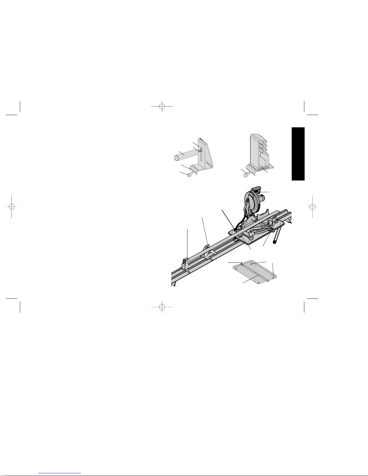
DW7301-Work Support (Fig.1)
a. The work support has a security screw (A) to capture the rail
and keep it from being knocked off the rails by your material.
b. Assemble the composite nylon work support horn (B) to the
adjustable work support (C) using the 1 1/2” carriage bolt (D)
supplied engaging the shoulder of the carriage bolt in the slot.
Rotate the work support horn clockwise to tighten.
c. Install knob (E).
d. Install the adjustable work support by sliding it onto the beam
from the left end with the knob (E) facing front.
e. After the saw is mounted to the beam, you can adjust the work
support horn until its height matches the height of the saw
table. Raise or lower the horn until it just contacts a straight
edge laid across the saw table. (Fig. 3) Rotate the horn clock-
wise to tighten in place.
DW7302-Work Stop (Fig.2)
a. Slide the work stop onto the rails from the left end.
b. Install the knob (A).
c. Position the work stop in the desired position and tighten knob (A)
to secure.
DW730/MiterSawWkStn 5/2/02 10:48 AM Page 4
Page 4
English
Miter Saw Mounting (Fig.3)
NOTE: Four rubber feet have been provided with the tool mount.
(Fig. 3) Should you decide to leave your miter saw on the tool mount
and remove the assembly from the rails, these feet facilitate a stable
base that will not slide during use. Assemble the feet to the underside of the tool mount with the four #10 1”(25mm) self-tapping
screws in the holes provided.
NOTE: The miter saw must be able to be positioned on the tool
mount so that all four corners can be bolted to the mount. If this is
not possible or if the saw obstructs the tool mount locking knobs,
please call D
EWalt Industrial Tools at 1-800-4-DEWalt (433-9258) for
technical assistance.
Saw Mounting Instructions (DW704 and
DW705)Fig.5
The mount has been pre-drilled for the DW704 and DW705:
Slide the tool mount onto the beam by inserting the flat bar between
the T-tracks. Position the tool mount on the right end of the beam
with the tape measure clamp facing toward the left. Secure the tool
mount unit to the beam by turning the locking knobs until snug.
a. Place the saw on the tool mount and orient it so the enclosed 2 3/4”
hex head bolts and flat washers can be inserted through the miter
saw base and tool mount. Secure each bolt loosely with another
flat washer and self-locking nuts.
b. Re-check saw fence and work support alignment by placing a
straight-edge along the back of the saw fence and the back of the
work support.(Fig. 3)
c. Securely tighten the self-locking nuts.
d. Loosen the tool mount locking knobs, check movement of the tool
mount along the rail, and tighten the locking knobs.
2
FIG. 1
FIG. 2
FIG. 3
WORK SUPPORT
WORK STOP
A
B
C
D
E
A
TAPE CLIP
FEET
FLAT BAR
LOCKING KNOBS
STRAIGHT EDGE
WORK STOP
WORK SUPPORT
DW708
TAPE
CLAMP
DW730/MiterSawWkStn 5/2/02 10:48 AM Page 5
Page 5

English
Slide the tool mount onto the beam by inserting the flat bar
between the T-tracks. Position the tool mount on the right end of
the beam with the tape measure clamp facing toward the left.
Secure the tool mount unit to the beam by turning the locking
knobs until snug.
Holes must be drilled in order to secure the saw to the tool mount.
When properly installed, the saw fence is aligned with the work
support so that the material you cut is square to the saw fence.
(Fig. 3) Before drilling any mounting holes, ensure that the saw
fence is aligned with the vertical face of the work support.
a. Place the saw on the tool mount, centering it left-to-right. Place
a straight edge against the saw fence and align the saw with the
vertical face of the work support. See Figure 3.
b. Mark the mounting holes on the tool mount.
c. Remove the saw and drill 7/16” holes at each location.
d. Place the miter saw on the tool mount.
e. Insert hex head bolts with flat washers through the saw base and
tool mount and loosely install flat washers and self-locking nuts
under the tool mount.
NOTE: The enclosed hardware is designed to secure D
EWalt miter
saws. Other miter saws may require a different length bolt for
proper fastening. The bolt must be long enough to allow 2 threads
to protrude through the self-locking nut.
f. Re-check saw fence and work support alignment by placing a
straight-edge along the face of the saw fence and the face of the
work support. See Figure 3.
g. Securely tighten the self-locking nuts.
h. Loosen the locking knobs, check movement of the tool mount
along the rail, and tighten the locking knobs.
3
Saw Mounting Instructions: (DW708)
NOTE:The DW730 has been pre-drilled for the DW708 sliding
compound miter saw. The tool mount must re-oriented 180˚
prior to mounting. When mounting the DW708 leave the rear
mounted stabilizer bars attached to the saw to ensure maximum stability.
1. Remove the two black knobs.
2. Remove the center bolt.
3. Remove the flat bar and rotate the tool mount 180 degrees.
4. Replace the center bolt and tighten it securely.
5. Replace the two black knobs.
Slide the tool mount onto the beam by inserting the flat bar between
the T-tracks. Position the tool mount on the right end of the beam
with the tape measure clamp facing toward the left. Secure the tool
mount unit to the beam by turning the locking knobs until snug.
a. Place the saw on the tool mount and orient it so the enclosed 2 3/4”
hex head bolts can be inserted through the miter saw base and tool
mount. Secure the bolts loosely with the flat washer and self-locking nuts.
b. Re-check saw fence and work support alignment by placing a
straight-edge along the back of the saw fence and the back of the
work support.
c. Securely tighten the self-locking nuts.
d. Loosen the locking knobs, check movement of the tool mount along
the rail, and tighten the locking knobs.
Mounting all other miter saws
T est fit your miter saw to the tool mount. If all four corners of the saw
are not on the tool mount after alignment of the saw fence and the
work support, the tool mount may need to be re-oriented 180˚.
Remove the saw and perform steps 1 through 5 above before proceeding.
DW730/MiterSawWkStn 5/2/02 10:48 AM Page 6
Page 6
4
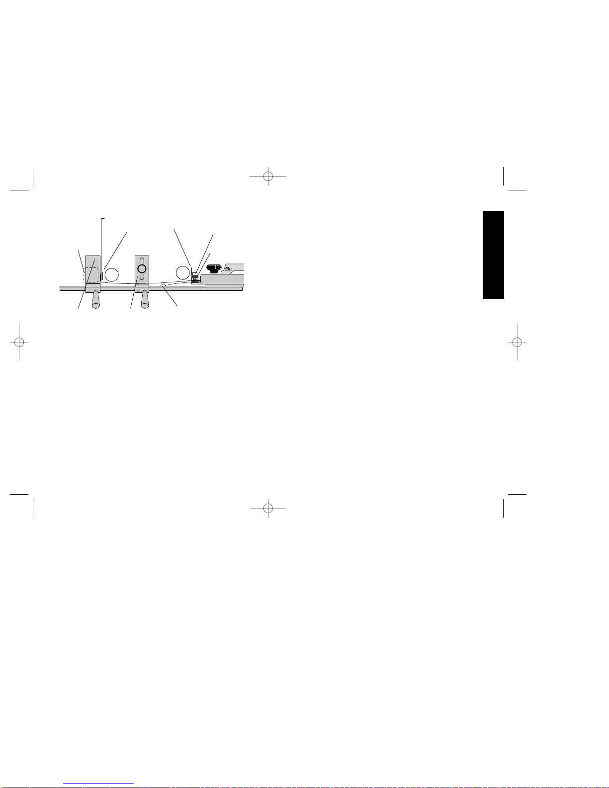
Measuring System Calibration (Fig.4)
The DW730 allows you to use a standard tape measure to easily
and accurately measure work to be cut. To ensure optimum accuracy, the unit must be calibrated prior to use.
a. Slide the work stop to approximately 3 feet from the miter saw
blade. Lock the work stop in place.
b. Position the miter saw blade at 90 degrees and lock the tool
mount in place by tightening the two black knobs.
c. Using a standard 3/4” wide, 12’ or 16’ tape measure, measure
the distance between the right edge of the work stop and the left
set of a saw blade tooth. For optimum accuracy, it is vital to
remember this measurement exactly.
d. Mount the tape measure in the work stop by sliding the belt clip
over the lip inside the work stop. Pull the end of the tape out and
flip the black tape clip down.
e. Pull the tape out, routing it under the black work support horn.
FIG. 4
SIGHT LINES
TAPE MEASURE
PLASTIC CLAMP
SCREW
WORK SUPPORT
WORK STOP
TAPE
MEASURE
(NOT
INCLUDED)
TAPE CLAMP
TAPE CLIP
English
A
B
Fold the tape back so the end is underneath and slide the top of
the tape into the tape clamp underneath the plastic clamp screw.
Route the end of the tape measure back through the tape clamp
so it rests on the rail between the two tracks. (Fig. 4)
f. Pull the tape measure out of the work stop until you read the mea-
surement obtained in step c. Line this measurement up exactly
at the right edge of the black tape clip(Fig. 4)(A). Since you have
not moved the saw or the work stop, you can calibrate the tape
measure to the edge of the tape clip and use that point as your
reference. This is where you will set the desired work length when
using the DW730. When you have positioned the tape at the
proper mark, tighten the plastic clamp screw. Your DW730
should now be calibrated.
g. If you choose to verify the calibration, loosen the work stop and
slide it to a specific measure; for example, 40.0”. Now, cut a piece
of scrap wood and measure. The length should be exactly the
same as the work stop reading. If it is not, re-calibrate the DW730
by starting at step “a” above.
h. After completion of work with the DW730, you may wish to
remove your saw and tape measure. Before doing so, record the
reading at the left edge of the tape clamp (Fig. 4)(B). You may
choose to make a mark on the tape measure, or use a pencil and
write the measurement down on the tool mount next to the tape
clamp. The next time you set up the DW730, simply mount the
tape measure in the work stop as before, and clamp the tape in
the tape clamp at the calibration setting. As long as the saw is still
mounted in the same location, the DW730 will again be calibrated.
Stowage
a. Remove the tape measure by loosening the plastic clamp screw
and sliding the tape from the work stop.
b. Loosen the black knobs on the tool mount and slide the saw off
DW730/MiterSawWkStn 5/2/02 10:48 AM Page 7
Page 7

English
In addition to the warranty, DEWALT tools are covered by our:
30 DAYNO RISK SATISFACTION GUARANTEE
If you are not completely satisfied with the performance of your
D
EWALT heavy duty industrial tool, simply return it to the partici-
pating seller within 30 days for a full refund. Please return the
complete unit, transportation prepaid. Proof of purchase may be
required.
5
of the rail. It is not necessary to remove the saw from the tool
mount. There are four feet on the bottom of the mount that allow
the saw to be used on any flat surface while still fastened to the
tool mount.
c. The work stop and work support may be removed or left on at the
discretion of the user. Tip the DW730 on its side and fold all four
legs by sliding the brass locking pin out of its detent, fold the leg,
and ensure that the brass locking pin engages the detent in the
folded position.
Accessories
Recommended accessories for use with your tool are available at
extra cost from your distributor or local service center.
CAUTION: The use of any non-recommended accessory may
be hazardous.
Important
To assure product SAFETY and RELIABILITY, repairs, maintenance and adjustment should be performed by authorized service
centers or other qualified service organizations, always using
identical replacement parts.
Full Warranty
DEWALT heavy duty industrial tools are warranted for one year
from date of purchase. We will repair, without charge, any defects
due to faulty materials or workmanship. For warranty repair information, call 1-800-4-D
EWALT. This warranty does not apply to
accessories or damage caused where repairs have been made or
attempted by others. This warranty gives you specific legal rights
and you may have other rights which vary in certain states or
provinces.
DW730/MiterSawWkStn 5/2/02 10:48 AM Page 8
Page 8

Modèle DW730 - Poste de travail de 2.2 m
(7 pi) à pattes pliantes pour scies à
onglets
Le poste de travail est conçu pour servir avec la plupart des scies à
onglets. On peut également l'utiliser avec la scie coulissante à
onglets mixtes, modèle DW708, après y avoir apporté quelques
modifications. Voir la rubrique relative au montage pour obtenir de
plus amples renseignements. En cas de problème de centrage ou
de montage, composer le 1 (800 4-DeWalt (433-9258).
MISE EN GARDE : Lire et comprendre toutes les mesures de
sécurité avant d'utiliser le présent accessoire ou tout autre accessoire avec une scie à onglets.
Outils requis
1. Un niveau ou une règle de précision de 1,1 m (3 pi)
2. Un ruban à mesurer de 19 mm (3/4 po) de largeur sur 4,0 m (12
pi) ou 4,9 m (16 pi) de longueur
3. Un jeu de douilles ou de clés
4. Une perceuse avec un foret de 11 mm (7/16 po)
5. Un tournevis à lame Phillips
Mesures de sécurité relatives aux accessoires de scies à onglets
• Ouvrir complètement les pattes pliantes avant de placer l'outil sur
le support.
• Porter des lunettes de sécurité lorsqu'on utilise une scie à
onglets.
• Le poste de travail est conçu pour soutenir 136 kg (300 lb) en
toute sécurité dans une zone de travail. Il est toutefois déconseillé d'y monter ou de s'y asseoir.
• Bien respecter les consignes de montage. Bien fixer l'outil au sup-
port de la façon indiquée. Ne jamais utiliser des brides temporaires lorsqu'on se sert d'une scie à onglets.
• Ne pas modifier le poste de travail ni s'en servir pour une utilisation non recommandée.
• Le poste de travail est conçu pour servir sur une surface plane et
stable. Il est dangereux de s'en servir sur une surface inégale.
PRÉPARATIFS
Placer le support de la scie à onglets sur le sol avec les pattes
pliées sur le dessus. Enfoncer la tige de verrouillage en laiton et
déplier chaque patte jusqu'à ce que la tige de verrouillage s'enclenche. Soulever le support par la poutre centrale et le placer à
l'endroit. Le support doit être stable et il ne devrait pas bercer.
Vérifier si les tiges de verrouillage des pattes sont bien enclenchées
et si les pattes sont bien retenues en place.
Assemblage
Modèle DW7301 - Soutien (Fig. 1)
a. Le soutien comporte une vis de fixation permettant de fixer le rail
et d'empêcher le soutien d'être expulsé des rails par le matériau.
b. Fixer le rebord en nylon composite (A) au soutien réglable (B) à
l'aide du boulon de carrosserie (C) de38 mm (1 1/2 po) fourni en
insérant l'épaule du boulon de carrosserie dans la fente. Faire
tourner le rebord du soutien dans le sens horaire pour le serrer.
c. Installer le bouton (D).
d. Installer le soutien réglable en le faisant glisser sur la poutre à par-
tir de la gauche en plaçant le bouton (E) vers l'avant.
e. Lorsque la scie est installée sur la poutre, on peut régler le rebord
du soutien jusqu'à ce que sa hauteur corresponde à celle de la
table. Soulever ou abaisser le rebord jusqu'à ce qu'il entre en contact avec une règle de précision déposée sur la table de la scie.
Faire tourner le rebord dans le sens horaire afin de fixer le tout.
Français
6
DW730/MiterSawWkStn 5/2/02 10:48 AM Page 9
Page 9

7
Modèle DW7302 - Butée (Fig. 2)
a. Faire glisser la butée sur les rails à partir de la gauche.
b. Installer le bouton (A).
c. Placer la butée dans la position voulue et serrer le bouton (A) pour
la fixer en place.
Montage de la scie à onglets (Fig. 3)
NOTE : Le dispositif de fixation de l'outil comporte quatre pattes de
caoutchouc (fig. 3). Lorsqu'on décide de laisser la scie à onglets
sur le dispositif de fixation et de retirer l'assemblage des rails, ces
pattes procurent une base stable et empêchent le glissement pendant l'utilisation. Installer les pattes dans les trous prévus à cet effet
sur la face inférieure du dispositif de fixation de l'outil à l'aide de
quatre vis autotaraudeuses n° 10 de 25 mm (1 po).
NOTE : La scie à onglets doit pouvoir être placée sur le dispositif
de fixation de sorte qu'on puisse en boulonner les quatre coins au
dispositif. Lorsque ce n'est pas le cas ou lorsque la scie nuit au
fonctionnement des boutons de verrouillage du dispositif de fixation,
prière de communiquer avec le soutien technique de DeWalt
Industrial Tools en composant le 1 (800) 4-DeWalt (433-9258).
Instructions relatives au montage de la
scie (Modèles DW704 et DW705) (Fig. 5)
Le dispositif de fixation est déjà percé pour l'installation d'une scie
de modèle DW704 ou DW705.
Faire glisser le dispositif de fixation de l'outil sur la poutre en insérant
la barre de fer entre les voies en T. Placer le dispositif de fixation à
l'extrémité droite de la poutre avec la bride du ruban à mesurer vers
la gauche. Fixer le dispositif à la poutre en faisant tourner les boutons de verrouillage jusqu'à ce qu'ils soient bien serrés.
a. Placer la scie sur le dispositif de fixation et l'orienter de façon à
pouvoir passer les boulons à tête hexagonale de 69 mm (2 3/4
po) et les rondelles plates à travers le socle de la scie et le dis-
Français
FIG. 1
FIG. 2
FIG. 3
SOUTIEN
BUTÉE
A
B
C
D
E
A
PINCE À
RUBAN
PATTES
BARRE DE FER
BOUTONS DE VER-
ROUILLAGE
LIGNES FINES
BUTÉE
SOUTIEN
DW708
RUBAN À
MESURER
DW730/MiterSawWkStn 5/2/02 10:48 AM Page 10
Page 10

ofreinés.
b. Revérifier le centrage du guide de la scie et du soutien en plaçant
une règle de précision le long de l'arrière du guide de la scie et de
l'arrière du soutien.
c. Bien serrer les écrous autofreinés.
d. Relâcher les boutons de verrouillage, vérifier le déplacement de
l'outil le long du rail et serrer les boutons de verrouillage.
Montage de tous les autres modèles de
scies à onglets
Placer la scie à onglets contre le dispositif de fixation de l'outil pour
en vérifier la compatibilité. Lorsque les quatre coins de la scie ne
sont pas sur le dispositif de fixation de l'outil après avoir aligné le
guide de la scie sur le soutien, il peut être nécessaire de déplacer le
dispositif de fixation de l'outil sur 180°. Enlever la scie et répéter les
étapes 1 à 5 précédentes.
Faire glisser le dispositif de fixation de l'outil sur la poutre en insérant
la barre de fer entre les voies en T. Placer le dispositif de fixation à
l'extrémité droite de la poutre avec la bride du ruban à mesurer vers
la gauche. Fixer le dispositif à la poutre en faisant tourner les boutons de verrouillage jusqu'à ce qu'ils soient bien serrés.
Il faut percer des trous afin de fixer la scie au dispositif de fixation de
l'outil. Lorsque la scie est bien installée, son guide est centré sur le
soutien de sorte que le matériau coupé est perpendiculaire au guide
(fig. 3). Avant de percer des trous, s'assurer que le guide est aligner sur la face verticale du soutien.
a. Installer la scie sur le dispositif de fixation de l'outil, en la centrant
de gauche à droite. Placer une règle de précision contre le guide
de la scie et aligner la scie sur la face verticale du soutien (fig. 3).
b. Marquer l'emplacement des trous de montage sur le dispositif de
fixation de l'outil.
c. Enlever la scie et percer des trous de 12 mm (7/16 po) à chaque
emplacement.
8
Français
positif de fixation. Installer chaque boulon lâchement avec une
autre rondelle plate et les écrous autofreinés.
b. Revérifier le centrage du guide de la scie et du soutien en plaçant
une règle de précision le long de l'arrière du guide de la scie et de
l'arrière du soutien (fig. 3).
c. Bien serrer les écrous autofreinés.
d. Relâcher les boutons de verrouillage du dispositif de fixation de
l'outil, vérifier le déplacement de l'outil le long du rail et serrer les
boutons de verrouillage.
Instructions relatives au montage de la
scie (Modèle DW708)
NOTE : Le poste de travail est déjà percé pour l'installation d'une
scie coulissante à onglets mixtes de modèle DW708. Il faut
déplacer sur 180° le dispositif de fixation de l'outil avant de procéder
au montage. Lorsqu'on installe une scie (modèle DW708), laisser
les stabilisateurs fixés à l'arrière en place afin d'en maximiser la stabilité.
1. Retirer les deux boutons noirs.
2. Retirer le boulon du centre.
3. Retirer la barre de fer et faire tourner la planche sur 180 degrés.
4. Remettre le boulon du centre en place et bien le serrer.
5. Remettre en place les deux boutons noirs.
Faire glisser le dispositif de fixation de l'outil sur la poutre en insérant
la barre de fer entre les voies en T. Placer le dispositif de fixation à
l'extrémité droite de la poutre avec la bride du ruban à mesurer vers
la gauche. Fixer le dispositif à la poutre en faisant tourner les boutons de verrouillage jusqu'à ce qu'ils soient bien serrés.
a. Placer la scie sur le dispositif de fixation et l'orienter de façon à
pouvoir passer les boulons à tête hexagonale de 69 mm (2 3/4
po) à travers le socle de la scie et le dispositif de fixation. Installer
les boulons lâchement avec la rondelle plate et les écrous aut-
DW730/MiterSawWkStn 5/2/02 10:48 AM Page 11
Page 11

9
ruban pour le faire sortir et abaisser la pince noire à ruban.
e. Faire sortir le ruban en le dirigeant sous le rebord noir du soutien.
Plier le ruban vers l'arrière pour en fixer l'extrémité au rebord et
faire glisser le haut du ruban dans la pince à ruban sous la vis de
serrage en plastique. Diriger l'extrémité du ruban de nouveau par
la pince à ruban de sorte que le ruban repose sur le rail entre les
deux voies (fig. 4).
f. Faire sortir le ruban à mesurer de la butée jusqu'à l'obtention de la
mesure obtenue à l'étape c. Aligner cette mesure exactement à
l'extrémité droite de la pince à ruban noire (fig. 4) (A). Puisque la
scie ni la butée n'ont été déplacées, le ruban à mesurer peut être
étalonné au rebord de la pince à ruban et on peut se servir de ce
point comme référence. C'est à cet endroit qu'il faut régler la
longueur du matériau lorsqu'on utilise le poste de travail, modèle
DW730. Lorsque le ruban est placé au bon endroit, serrer la vis de
serrage en plastique. Le poste de travail, modèle DW730, est
alors étalonné.
g. Lorsqu'on veut vérifier l'étalonnage, desserrer la butée et la faire
glisser à une mesure spécifique (40,0 po, par exemple). Couper
Français
d. Installer la scie à onglets sur le dispositif de fixation de l'outil.
e. Passer les boulons à tête hexagonale à travers le socle de la scie
et le dispositif de fixation et installer lâchement les rondelles plates
et les écrous autofreinés sous le dispositif de fixation de l'outil.
NOTE : Les ferrures fournies servent à installer des scies à onglets
DeWalt. Il peut être nécessaire d'utiliser des boulons de longueur différente pour installer convenablement d'autres modèles de scies à
onglets. Le boulon doit être suffisamment long pour laisser dépasser deux filets de l'écrou autofreiné.
f.Revérifier le centrage du guide de la scie et du soutien en plaçant une
règle de précision le long de l'arrière du guide de la scie et de l'ar-
rière du soutien (fig. 3).
g. Bien serrer les écrous autofreinés.
h. Relâcher les boutons de verrouillage, vérifier le déplacement de
l'outil le long du rail et serrer les boutons de verrouillage.
Étalonnage du système de mesure (Fig.4)
Le poste de travail, modèle DW730, permet de se servir d'un ruban
à mesurer standard et de mesurer avec précision le matériau à
couper. Afin d'en optimiser la précision, le poste doit être étalonné
avant de servir.
a. Faire glisser la butée à environ 276 cm (3 pi) de la lame de la scie
à onglets. Verrouiller la butée en place.
b. Fixer la lame de la scie à 90° et verrouiller le dispositif de fixation de
l'outil en place en serrant les deux boutons noirs.
c. À l'aide d'un ruban à mesurer standard de 19 mm (3/4 po) de
largeur sur 3,6 m ou 4,9 m (12 pi ou 16 pi) de longueur, mesurer
la distance entre le rebord droit de la butée et le jeu gauche de dent
de lame. Afin d'optimiser la précision de la lecture, il est essentiel
de s'en rappeler exactement.
d. Installer le ruban dans la butée en faisant glisser la pince pour la
ceinture sur la lèvre à l'intérieur de la butée. Tirer sur l'extrémité du
FIG. 4
LIGNES FINES
RUBAN À MESURER
VIS DE SERRAGE
EN PLASTIQUE
SOUTIEN
BUTÉE
RUBAN À
MESURER
BRIDE À
RUBAN
PINCE À RUBAN
A
B
DW730/MiterSawWkStn 5/2/02 10:48 AM Page 12
Page 12

Important
Pour assurer la SÉCURITÉ D’EMPLOI et la FIABILITÉ de l’outil,
n’en confier la réparation, l’entretien et les rajustements qu’au personnel d'un centre de service ou d'un atelier d’entretien autorisé n’utilisant que des pièces de rechange identiques.
Garantie complète
Les outils industriels de service intensif DeWALT sont garantis pendant un an à partir de la date d’achat. Toute pièce d’un outil
DeWAL Tqui s’avérait défectueuse en raison d’un vice de matière ou
de fabrication sera réparée ou remplacée sans frais. Pour obtenir
de plus amples renseignements sur les réparations couvertes par la
garantie, composer le 1 (800) 4-DeWALT (1 (800) 433-9258). La
présente garantie ne couvre pas les accessoires ni les dommages
causés par des réparations tentées ou effectuées par des tiers. Les
modalités de la présente garantie donnent des droits légaux spécifiques. L'utilisateur peut également se prévaloir d'autres droits selon
l'état ou la province qu'il habite.
En outre, la garantie suivante couvre les outils DeWALT.
GARANTIE DE SATISFACTION DE 30 JOURS OU ARGENT
REMIS
Si, pour quelque raison que ce soit, l'outil industriel de service intensif DeWalt ne donne pas entière satisfaction, il suffit de le retourner
chez le marchand participant dans les 30 jours suivant la date
d'achat afin d'obtenir un remboursement complet. Il faut retourner,
port payé, l'outil complet. On peut exiger une preuve d'achat.
10
Français
ensuite un bout de bois inutile et le mesurer. Il devrait avoir exactement la même longueur que la mesure choisie. Lorsque ce n'est
pas le cas, il faut étalonner de nouveau le poste de travail, modèle
DW730, en recommençant à l'étape «a» précédente.
h. Après avoir terminé une tâche sur le poste de travail, on peut
vouloir en retirer la scie et le ruban à mesurer. Il faut au préalable
consigner la lecture prélevée au rebord gauche de la pince à
ruban (fig. 4) (B). On peut alors faire une marque sur le ruban ou
inscrire la mesure à l'aide d'un crayon sur le dispositif de fixation de
l'outil près de la pince à ruban. Ainsi, lors de la prochaine utilisation du poste de travail, il suffit d'installer le ruban à mesurer dans
la butée de la façon décrite précédemment et de le fixer dans la
pince à ruban au réglage étalonné. Tant que la scie est installée
au même endroit, le poste de travail reste étalonné.
Rangement
a. Retirer le ruban à mesurer en desserrant la vis de serrage en plas-
tique et en faisant glisser le ruban hors de la butée.
b. Desserrer les boutons noirs du dispositif de fixation de l'outil et faire
glisser la scie hors des rails. Il n'est pas nécessaire de retirer la
scie du dispositif de fixation de l'outil. Les quatre pattes du dispositif permettent d'utiliser la scie sur toute surface plane.
c. L'utilisateur peut décider de retirer ou non la butée et le soutien.
Renverser le poste de travail sur le côté et en plier les quatre pattes
en faisant glisser la tige de dégagement de laiton hors de son dispositif de retenue, en pliant la patte et en s'assurant que la tige de
dégagement de laiton s'enclenche dans le dispositif de retenue de
la position pliée.
Accessoires
Les accessoires recommandés pour l’outil sont vendus séparément
chez les détaillants et au centre de service de la région.
MISE EN GARDE : L’utilisation de tout accessoire non recom-
mandé peut être dangereuse.
DW730/MiterSawWkStn 5/2/02 10:48 AM Page 13
Page 13

11
DW730 - Estación de trabajo para sierra
angular de 2,13 m (7’) con patas plegables
Esta estación de trabajo está diseñada para emplearse con la mayoría de las sierras angulares. Puede utilizarse también con la sierra
de inglete compuesto DW708 con algunas modificaciones. Consulte
la sección de montaje para conocer los detalles. Si tiene cualquier
problema con la alineación o con el montaje por favor llame al 326-
7100.
PRECAUCIÓN: Lea y comprenda todas las instrucciones de
seguridad antes de utilizar este o cualquier otro accesorio con la
sierra angular.
Herramientas requeridas
1. Nivel de 90 cm (3’) o una regla.
2. Flexómetro de 3,6 m (12 ft.) o 5 m (16 ft.) por 19 mm (3/4”).
3. Juego de llaves o de dados.
4. Taladro con broca de 7/16” (11 mm).
5. Destornillador Phillips.
Instrucciones generales de seguridad
para accesorios de sierra angular
• Abra completamente las patas plegables antes de colocar la her-
ramienta en la base.
• Debe utilizar gafas de seguridad cuando utilice una sierra angu-
lar.
• Esta estación de trabajo está diseñada para soportar hasta 136
kg (300 lbs.) de manera segura en el espacio de trabajo. No es
seguro pararse, sentarse y trepar en la estación de trabajo.
• Siga cuidadosamente las instrucciones de montaje. Fije la her-
ramienta a la base de manera segura como se le indica. Nunca
debe utilizar prensas temporales cuando trabaje con una sierra
angular.
• No modifique ni utilice la estación de trabajo para una operación
para la que no está destinada.
• La base está diseñada para usarse en una superficie plana y
estable. Utilizarla en una superficie irregular es peligroso.
PREPARACIÓN
Coloque la base para sierra angular en el suelo con la patas plegadas hacia arriba. Empuje el perno de seguridad de latón y tire de
cada pata hasta que el perno de seguridad haga clic en el retén.
Levante la base por la viga central y colóquela en la posición de trabajo. La base deberá ser estable y no deberá balancearse. Revise
las patas para asegurarse que los pernos de seguridad engancharon y que las patas estén firmes en su posición.
Ensamblaje
Soporte de trabajo DW7301 (Fig. 1)
a. La estación de trabajo tiene un tornillo de seguridad para capturar
el riel y evitar que salga de su sitio con el material.
b. Ensamble el cuerno de nylon (A) al soporte ajustable (B) con el
tornillo de carro de 1 1/2” que se suministra enganchando el hombro del tornillo de carro en la ranura. Gire el cuerno del soporte de
trabajo en el sentido de las manecillas del reloj para apretarlo.
c. Instale la perilla.
d. Instale el soporte de trabajo ajustable deslizándolo en la viga
desde el extremo izquierdo con la perilla (E) hacia el frente.
e. Después de montar la sierra en la viga, puede ajustar el cuerno del
soporte de trabajo hasta que su altura concuerde con la altura de
la mesa de la sierra. Suba o baje el cuerno hasta que apenas haga
contacto con una regla que se coloque en la mesa de la sierra.
Gire el cuerno en el sentido de las manecillas del reloj para apretarlo en posición.
Español
DW730/MiterSawWkStn 5/2/02 10:48 AM Page 14
Page 14

Tope de trabajo DW7302 (Fig. 2)
a. Deslice el tope sobre los rieles desde el extremo izquierdo.
b. Instale la perilla (A).
c. Coloque el tope en la posición deseada y apriete la perilla (A) para
asegurarlo.
Montaje de la sierra angular (Fig. 3)
NOTA: Se han provisto cuatro regatones de goma con la base de
la herramienta (Fig. 3). Si usted decide dejar la sierra angular en
base y quitar el montaje de los rieles, estos regatones facilitan estabilizar la base mientras no se utilice de manera deslizable.
Ensamble los regatones a la parte inferior de la base con los cuatro
tornillos auto roscantes # 10 de 25 mm (1”) que se le proporcionan.
NOTA:La sierra angular debe poder colocarse en la base de la herramienta de manera que puedan atornillarse las cuatro esquinas. Si
esto no es posible o si la sierra obstruye las perillas de montaje de
la herramienta, por favor llame al 326-7100 para recibir asistencia
técnica.
Instrucciones de montaje de la sierra
(DW704 y DW705)
El montaje se ha pre barrenado para los modelos DW704 y DW705
Deslice la base de la herramienta en la viga insertando la barra
plana entre los rieles. Coloque la base en el extremo derecho de la
viga con la pinza para la cinta métrica apuntando hacia la izquierda. Asegure la unidad de la base de la herramienta a la viga girando las perillas hasta apretarlas.
a. Coloque la sierra sobre la base y oriéntela de manera que los
tornillos de 44 mm (2-3/4”) con cabeza hexagonal se puedan insertar a través de la base de la sierra angular y la base de la estación
de trabajo. Asegure los tornillos sin apretarlos con la roldana plana
y las tuercas auto asegurables.
12
Español
FIG. 1
FIG. 2
FIG. 3
SOPORTE DE TRABAJO
A
B
C
D
E
A
SUJETADOR
PARA CINTA
MÉTRICA
REGATONES
BARRA
PLANA
PERILLAS DE
SEGURIDAD
REGLA
DW708
PINZA PARA
CINTA
TOPE DE TRABAJO
TOPE DE
TRABAJO
SOPORTE DE
TRABAJO
DW730/MiterSawWkStn 5/2/02 10:48 AM Page 15
Page 15

13
c. Retire la sierra y perfore orificios de 7/16” (11 mm) en cada lugar .
d. Coloque la sierra angular sobre la base.
e. Inserte tornillos con cabeza hexagonal con roldanas planas a
través de la base de la sierra y la base para la herramienta y
coloque las roldanas y las tuercas auto asegurables sin apretar
bajo la base para la herramienta.
NOTA: La herramienta proporcionada está diseñada para fijar las
sierras angulares DeWALT. Otras sierra pueden requerir tornillos
de diferente longitud para sujetarse de manera apropiada. El
tornillo debe ser suficientemente largo para permitir que sobresalgan dos vueltas de cuerda de la tuerca auto asegurable.
f. Verifique la alineación de la guía de la sierra y el soporte de tra-
bajo colocando una regla a lo largo de la cara de la guía de la
sierra y la cara del soporte de trabajo.
g. Apriete con firmeza las tuercas auto asegurables.
h. Afloje las perillas de seguridad, verifique el movimiento de la
base de la herramienta a lo largo del riel y apriete de nuevo las
perillas de seguridad.
Español
b. Revise la alineación de la guía y el soporte de trabajo colocando
una regla a lo largo de la guía de la sierra y en la parte posterior
del soporte de trabajo.
c. Apriete con firmeza las tuercas auto asegurables.
d. Afloje las perillas de seguridad, verifique el movimiento del monta-
je de la herramienta a lo largo del riel y apriete las perillas.
Instrucciones de montaje de la sierra:
(DW708 y otras sierras)
NOTA: Cuando monte la sierra DW708, deje las barras estabilizadoras posteriores instaladas en la sierra para asegurar la
máxima estabilidad.
1. Quite las dos perillas negras.
2. Quite el tornillo central.
3. Quite la barra plana y gírela 180 grados.
4. Coloque de nuevo la barra central y apriétela y asegúrela.
5. Coloque de nuevo las dos perillas negras.
PARAMONTAR OTRAS SIERRAS ANGULARES
NOTA: Deslice la base de la herramienta en la viga insertando la
barra plana entre los rieles T. Coloque la base en el extremo derecho de la viga con la pinza para la cinta métrica apuntando hacia la
izquierda. Asegure la base a la viga girando las perillas de seguridad hasta quedar apretadas.
Deben perforarse los orificios para poder asegurar la sierra a la
estación de trabajo. Cuando está instalada correctamente, la guía
de la sierra debe quedar alineada con la base de manera que el
material de trabajo esté a escuadra con respecto a la guía. Antes de
perforar los orificios de montaje, asegúrese que la guía esté alineada con la cara vertical del soporte de trabajo.
a. Coloque la sierra sobre la base, centrándola de izquierda a
derecha. Coloque una regla contra la guía de la sierra y alinee la
sierra con la cara vertical del soporte de trabajo.
b. Marque los orificios de montaje en la base de la herramienta.
FIG. 4
LÍNEAS DE
VISIÓN
CINTAMÉTRICA
TORNILLO DE SUJE-
CIÓN DE PLÁSTICO
SOPORTE DE TRABAJO
TOPE DE TRABAJO
CINTAMÉTRICA
PINZA PARA
LA CINTA
SUJETADOR DE LACINTA
A
B
DW730/MiterSawWkStn 5/2/02 10:48 AM Page 16
Page 16

una medida específica; por ejemplo 1,0 m (40”). Ahora corte una
pieza de material de desperdicio y mídalo. La longitud deberá ser
exactamente la misma que la lectura del tope de trabajo. Si no es
así, repita la calibración comenzando por el paso “a”.
h. después de haber terminado un trabajo con la estación DW730,
usted puede desear retirar su sierra y la cinta métrica. Antes de
hacerlo, apunte la lectura en el borde izquierdo de la pinza sujetadora de la cinta (Fig. 4) Puede hacer una marca en la cinta métrica, o utilizar un lápiz y escribir la medida en la base de la herramienta, junto a la pinza sujetadora de la cinta. La siguiente vez
que utilice la estación DW730, simplemente monte la cinta métrica
en el tope como lo hizo anteriormente, y fije la cinta en la pinza en
el sitio de calibración. Mientras la sierra permanezca montada en
el mismo sitio, la estación DW730 permanecerá calibrada.
Almacenaje
a. Retire la cinta métrica aflojando el tornillo de sujeción de plástico y
deslizando la cinta del tope de trabajo.
b. Afloje las perillas negras de la base de la herramienta y deslice la
sierra hacia fuera del riel. No es necesario quitar la sierra de la
base. Esta cuenta con cuatro patitas en la parte inferior para poder
colocar la sierra en cualquier superficie plana mientras esté unida
a la base.
c. El tope de trabajo y el soporte de trabajo puede quitarse o dejarse
a discreción del usuario. Coloque la estación de trabajo de lado y
pliegue las cuatro patas deslizando el perno de seguridad de latón
hacia fuera del retén. Pliegue la pata y asegúrese que el perno de
latón enganche con el retén en la posición plegada.
Accesorios
Los accesorios recomendados para usarse con su herramienta
están a su disposición con costo adicional con su distribuidor o centro de servicio locales.
14
Español
Calibración del sistema de medición (Fig.4)
La estación de trabajo DW730 le permite utilizar una cinta métrica
estándar para medir sus cortes de manera sencilla y precisa. Para
asegurar la máxima precisión, debe calibrar la unidad antes de usarla.
a. Deslice el tope de trabajo a aproximadamente 90 cm del disco de la
sierra angular. Asegure el tope en esta posición.
b. Coloque el disco de la sierra angular a 90 grados y asegure la base
en esa posición apretando las dos perillas negras.
c. Con una cinta métrica estándar de 3,6 o 5 metros por 19 mm (3/4”),
m ida la distancia entre el borde derecho del tope de trabajo y la
punta de un diente del disco de la sierra que esté inclinado hacia la
izquierda. Para obtener la mayor precisión, es vital recordar esta
medida con exactitud.
d. Monte la cinta métrica en el tope de trabajo deslizando el sujetador
sobre el borde interior del tope de trabajo. Empuje el extremo de la
cinta hacia afuera y pliegue el sujetador negro hacia abajo.
e. Tire de la cinta hacia afuera, guiándola bajo el cuerno negro del
soporte de trabajo. Doble la cinta hacia atrás de manera que el
extremo quede debajo y deslice la parte superior de la cinta dentro
de la pinza que se encuentra debajo del tornillo de sujeción de plástico. Guíe el extremo de la cinta hacia atrás, a través de la pinza de
manera que se apoye en el riel entre las dos guías (Fig. 4).
f. Tire de la cinta métrica hacia fuera del tope de trabajo hasta leer la
medida obtenida en el paso c. Haga coincidir exactamente esta
medida en el borde derecho del sujetador negro. Ya que no ha movido la sierra ni el tope de trabajo, puede calibrar la medida de la cinta
al borde del sujetador y utilizar ese punto como referencia. En este
momento usted ajusta el espacio de trabajo que desee cuando utiliza la estación de trabajo DW730. Una vez que haya posicionado la
cinta en la marca apropiada, apriete el tornillos de sujeción de plástico. Su estación DW730 está calibrada ahora.
g. Si desea verificar la calibración, afloje el tope de trabajo y deslícelo a
DW730/MiterSawWkStn 5/2/02 10:48 AM Page 17
Page 17

15
En adición a la garantía, las herramientas DeWALT están amparadas por nuestra:
GARANTÍA DE SATISFACCIÓN SIN RIESGO POR 30 DÍAS
Si usted no se encuentra completamente satisfecho con el desempeño de su herramienta industrial DeWALT, sencillamente devuélvala a los vendedores participantes durante los primeros 30 días
después de la fecha de compra para que le efectúen un reembolso
completo. Por favor regrese la unidad completa, con el transporte
pagado. Se puede requerir prueba de compra.
Español
PRECAUCIÓN: El uso de cualquier accesorio no recomendado
para emplearse con su herramienta puede ser peligroso.
Importante
Para garantizar la SEGURIDAD y la CONFIABILIDAD del producto,
las reparaciones, el mantenimiento y los ajustes deberán realizarse
en los centros de servicio autorizado Black & Decker u otras organizaciones de servicio calificado. Estas organizaciones prestan servicio a las herramientas DeWALT Y utilizan siempre refacciones
DeWALT. Los centros de servicio para herramientas industriales de
Black & Decker están certificados para dar servicio a las herramientas industriales DeWALT.
Garantía Completa
Las herramientas industriales DeWALT están garantizadas durante
un año a partir de la fecha de compra. Repararemos, sin cargos,
cualquier falla debida a material o mano de obra defectuosos.
Hemos hecho arreglos con la División de Herramientas Industriales
de Black & Decker para que hagan las reparaciones en garantía a
las herramientas DeWALT. Por favor regrese la unidad completa,
con el transporte pagado, a cualquier Centro de Servicio para
Herramientas Industriales de Black & Decker o a las estaciones de
servicio autorizado enlistadas bajo "Herramientas Eléctricas" en la
Sección Amarilla. Esta garantía no se aplica a los accesorios ni a
daños causados por reparaciones efectuadas por terceras personas. Esta garantía le otorga derechos legales específicos, y usted
puede tener otros derechos que pueden variar de estado a estado.
DW730/MiterSawWkStn 5/2/02 10:48 AM Page 18
 Loading...