

Page 1

SmartWireless® CX
www.detcon.com
Sensor Station for SmartWireless®
Mobile Gas Detection System
Operator’s Installation and Instruction Manual
DETCON, Inc.
4055 Technology Forest Blvd.,
The Woodlands, Texas 77381
Ph.713.559.9200 / Fax 281.298.2868
May 30, 2014 • Document #4409 • Revision 1.4
Page 2

This page left intentionally blank
Sentinel CX
Shipping Address: 4055 Technology Forest Blvd., The Woodlands Texas77381
Mailing Address: P.O. Box 8067, The Woodlands Texas 77387-8067
Phone: 713.559.9200 • Fax: 281.292.2860 • www.detcon.com • sales@detcon.com
Sentinel CX Sensor Station IM Rev. 1.4 ii
Page 3

Sentinel CX
Table of Contents
1. Introduction............................................................................................................................................1
1.1 Features ..........................................................................................................................................................1
1.2 Optional Components.....................................................................................................................................2
1.3 Alarms and Fault Condition ........................................................................................................................... 2
1.4 Power Supply-Internal Rechargeable Battery and Charging Accessory ........................................................ 3
1.5 Radio Module................................................................................................................................................. 4
1.6 Sensor Inputs.................................................................................................................................................. 5
1.7 Alarm Outputs................................................................................................................................................ 6
1.8 Power Switch.................................................................................................................................................. 8
1.9 Power Connector............................................................................................................................................ 8
1.10 Remote I/O Cabling Accessory and Safe Use ................................................................................................ 8
2. Safety Guidelines for safe use.............................................................................................................10
3. Installation............................................................................................................................................12
3.1 Initial Setup .................................................................................................................................................. 12
4. Recharging the Internal Battery Pack...............................................................................................18
4.1 Non-Hazardous and Indoor Location ...........................................................................................................18
4.2 Connecting to Mains Supply........................................................................................................................ 18
5. Maintenance and Service Personnel Activities..................................................................................19
5.1 Replacement of Condensation Prevention Packet ........................................................................................ 19
5.2 Replacement of Lithium Ion Battery Pack ................................................................................................... 19
5.3 Proper Cleaning Procedure........................................................................................................................... 19
5.4 Servicing Risks and Verification of Safe State after Servicing .................................................................... 20
6. Troubleshooting Guide........................................................................................................................21
7. Customer Support and Service Policy...............................................................................................22
8. Warranty Notice ..................................................................................................................................23
9. Appendix...............................................................................................................................................24
9.1 Specifications ............................................................................................................................................... 24
9.2 Spare Parts and Wireless Accessories .......................................................................................................... 25
9.3 Revision Log ................................................................................................................................................ 26
Table of Figures
Figure 1 SmartWireless® CX Sensor Station..................................................................................................1
Figure 2 SmartWireless® CXT Radio Module ...............................................................................................4
Figure 3 Sensor Input PCA..............................................................................................................................5
Figure 4 Sensor Input Connector Pin-out........................................................................................................6
Figure 5 Relay PCA.........................................................................................................................................6
Figure 6 External Alarm Connector pin out for ‘Wet’ alarm contacts ............................................................7
Figure 7 External Alarm Connector Pin out for ‘Dry’ alarm contacts.............................................................7
Figure 8 Power Connector...............................................................................................................................8
Figure 9 Mount CX on Tripod.......................................................................................................................13
Figure 10 Attach Sensor Brackets to Tripod .................................................................................................14
Figure 11 A1 C1D2 Alarm Connections .......................................................................................................14
Figure 12 Enclosure.......................................................................................................................................15
Figure 13 Connector to Transceiver ..............................................................................................................15
Figure 14 Battery Bracket in position............................................................................................................16
Sentinel CX Sensor Station IM Rev. 1.4 iii
Page 4

Sentinel CX
Figure 15 Battery and Battery Bracket ..........................................................................................................16
Figure 16 Battery Connections......................................................................................................................17
This page left intentionally blank
Shipping Address: 4055 Technology Forest Blvd., The Woodlands Texas77381
Mailing Address: P.O. Box 8067, The Woodlands Texas 77387-8067
Phone: 713.559.9200 • Fax: 281.292.2860 • www.detcon.com • sales@detcon.com
Sentinel CX Sensor Station IM Rev. 1.4 iv
Page 5

Sentinel CX
1. Introduction
1.1 Features
The SmartWireless® CX Sensor Station (Figure 1) is an accessory to the SmartWireless® CXT. The CX
wirelessly transmits the data from the sensors to the CXT and includes a battery that powers the radio,
alarm devices, and the attached sensors. The CX can sustain up to four 4-20mA wired sensors.
Remote mounted gas detection sensors include any analog 4-20maDC device such as;
toxic gas,
combustible gas, or
oxygen deficiency sensors.
Antenna
Strobe
Power
LED
4-20 Sensor Input PCA
& 4 Relay PCA
Optional
Ext Alarm
Connector
Power
Connector
RXT-320
Transceiver
Power
Switch
Sensor Ports
Battery Pack
Alarm Horn
Figure 1 SmartWireless® CX Sensor Station
The SmartWireless® CX Sensor Station package is a Division 2 assembly housed in a 316 stainless steel
enclosure that offers various connector options for multiple configurations.
System components of the SmartWireless® gas detection system include;
Smart Wireless CXT Controller
Smart Wireless CX Sensor Station,
alarm stations and
gas detection sensors.
Sentinel CX Sensor Station IM Rev. 1.4 Page 1 of 26
Page 6

Sentinel CX
SmartWireless® CXT Controller
The Detcon SmartWireless® CXT controller is a multi-channel mobile gas detection control system
mounted on a tripod or a suitable stand. The CXT can be utilized as a self-contained gas detection,
display/alarm system package or wirelessly connected to the main network. The CXT is equipped with an
auto configure system to automatically search for Detcon equipment associated with the controller.
SmartWireless® CX Sensor Station
The SmartWireless® CX Sensor Station is an accessory to the SmartWireless® CXT. The CX wirelessly
transmits the data from up to 4 wired sensors back to the CXT and includes a battery that powers the radio,
alarm devices, and the attached sensors.
Alarm Stations
Alarm stations can be used as part of the gas detection system. Class I Division 1 and Class I Division 2
alarm stations are available. The stations are battery powered and controlled wirelessly by the CXT. The
strobe and horn installed on the CX are activated by the CXT when the alarms levels are reached.
Alarm options are as follows:
1. Integral audio visual mounted on the CX (Class 1; Division 2 only)
2. Standalone audio visual alarm station (Class 1; Division 2)
3. Standalone audio visual alarm station (Class 1; Division 1)
Gas Detection Sensors
Gas sensors with a 4-20mA output can be connected directly to the CX. The Model CX sensors from
Detcon are designed specifically to work with the SmartWireless® CX.
Associated Accessories
The accessories associated for the CX Controller product are as follows:
Detcon Tripod
Detcon Battery Charging Accessory
Detcon Division 2 cables (various)
Detcon Operators Manual
1.2 Optional Components
Options for the SmartWireless® CX Sensor Station are as follows:
strobe
horn
external ‘Wet’ or ‘Dry’ alarm port
1.3 Alarms and Fault Condition
The CX Sensor Station includes an optional strobe and/or a piezoelectric horn and an external alarm
connector. The strobe is associated with Alarm 1, the horn is associated with Alarm2 and the external alarm
connector utilizes all alarm outputs (alarm 1, 2, 3 and fault) for connection to external alarm devices. The
external alarm outputs can be used to control annunciating devices or as signal inputs to other control
devices. The CX permits alarm and fault conditions to cause an assigned relay to fire, triggering external
alarm devices. When the alarm level is reached either the devices mounted to the box or attached to the
external alarm connector are activated, or both. The assigned relay outputs will return to normal state when
a gas alarm or a fault condition clears. The Alarm Relay Output can be either ‘Wet’ or ‘Dry’ determined
Sentinel CX Sensor Station IM Rev. 1.4 Page 2 of 26
Page 7

Sentinel CX
when the unit is ordered. The ‘Wet output connector provides 12V outputs for external alarms. The ‘Dry’
output connector provides dry contacts for external power to control external alarms.
All alarms can be configured as Energized/De-Energized, Latching/Non-Latching and Silenceable/NonSilenceable for the relays. This setup must be performed at the controller, refer to the controller manual for
more information.
1.4 Power Supply-Internal Rechargeable Battery and Charging
Accessory
SmartWireless® CX is powered by an internal rechargeable Smart Battery capable of delivering continuous
operation in a no alarm condition for two to eight weeks depending on the quantity and type of sensors tied
to the control panel. The internal re-chargeable battery pack shall only be charged in a non-hazardous area
where the required operating temperature limits are 0C to +45C. It may be used in the field and be
discharged in the temperature range of -20C to +60C.
The internal re-chargeable battery pack shall only be charged in a non-hazardous
area where the required operating temperature limits are 0C to +40C. Charging
CAUTION
outside this temperature range may degrade the life of the battery pack.
The Battery Pack Detcon PN 360-3S6PFP-290 contains an internal protection
circuit which maintains its safe operation against all potential hazard conditions.
CAUTION
No other Battery Pack except Detcon PN 360-3S6PFP-290 may be used in the
operation of this device.
CAUTION
The internal battery can only be recharged in a non-hazardous area and only using the Detcon supplied
Battery Charger Accessory that runs on AC power.
Detcon Approved Battery Charger Accessory Ratings:
AC Input Power
Voltage: 100-240 VAC, 50-60 Hz (requires correct PN version for optional 110 or 220 VAC use)
Current: 2.0 Amps maximum
DC Output Power
Voltage: 24+/- 1 VDC
Current: 3.1 Amps maximum
NOTE 1
Sentinel CX Sensor Station IM Rev. 1.4 Page 3 of 26
No other Battery Charger or VDC input power source may be used with this CX Controller
product.
Page 8

Sentinel CX
1.5 Radio Module
The SmartWireless® CX offers a wireless option to connect it to the SmartWireless CXT and other devices
wirelessly. The Radio Module includes a transceiver that operates at 2.4GHz and conforms to non-licensed
radio frequency usage worldwide. Spread spectrum technology supports integrity and security for the
wireless network.
The SmartWireless CXT and CX products use a wireless network with a mesh topology. If radio
communication directly between two devices is impossible due to distance or obstruction, each wireless
device is capable of locating an alternate route through an additional wireless device to communicate with
the designated device. This innovative technology is designed to create a robust network that automatically
routes around congestion and line-of-sight obstacles while improving throughput as subscriber device
density increases.
The radio module is housed in a black ABS box mounted inside of the CX stainless steel enclosure. The
standard package includes two PCAs mounted inside the black ABS box (radio PCA and Smart battery
charging PCA), 5 dB antenna, and a protective antenna cover. The battery PCA includes circuitry to safely
recharge the battery from a 24VDC input and a fuel gauge circuit to monitor the charge remaining in the
battery.
The radio PCA includes a 2.4Ghz radio and a rotary switch for setting the RF channel of the system (Figure
2). Use a small screwdriver to rotate the switch until the arrow points to the desired RF channel number (16
channels available, 0h-Fh).
NOTE
All devices within the network must be on the same RF channel to operate correctly.
Each radio module is required to have a unique address. These addresses typically start at 01h and continue
sequentially for each SmartWireless CX in the gas detection system. The radio PCA includes a pair of
rotary switches to set this address (Figure 2).
NOTE
The switch for the most significant digit (MSD) is on the right and the least significant digit
(LSD) is on the left.
Modbus
Address LSD
Switch
RF Channel
Selector Switch
Modbus
Address MSD
Switch
Figure 2 SmartWireless® CXT Radio Module
Sentinel CX Sensor Station IM Rev. 1.4 Page 4 of 26
Page 9

Sentinel CX
1.6 Sensor Inputs
The SmartWireless® CX Sensor Station includes a Sensor Input PCA that accepts 4-20mA inputs from up
to 4 attached sensors. The PCA includes two rotary switches to set its Modbus address (Figure 3). This
address is set to 01 for SmartWireless® systems using a CXT or Model X40 controller. If an MCX-32
controller is being used, this address needs to be unique for each CX Sensor Station in the system. For an
MCX-32 system, the addresses should start at 40h and continue sequentially for each CX in the system.
Sensor Connector Ratings
Voltage: 9-11.2 VDC
Current: 100 mA max through any single sensor connector
Modbus Address
LSD Switch
Modbus Address
MSD Switch
Figure 3 Sensor Input PCA
Four "quick connects" on the side of the CX are for sensor connection (Figure 4), supply power to the
sensor from the internal battery and accept the 4-20mA signal from the sensor.
NOTE
Power supplied to the sensors is 11VDC. Any attached sensor must be designed to work at
this voltage level.
The four sensor input lines are fused at the PC board level for safety purposes. These fuses are not
designed for field replacement and shall not under any circumstances be attempted to be changed out by
anyone but Detcon Factory trained Service personnel.
These PC board mounted fuses are not designed for field replacement and shall not
under any circumstances be attempted to be changed out by anyone but Detcon
CAUTION
Factory-Trained Service personnel.
Sentinel CX Sensor Station IM Rev. 1.4 Page 5 of 26
Page 10

Sentinel CX
Enclosure
PCB
3
4
Shld (Green) 4
PWR (Red) 3
4-20mA (White) 2
GND (Black) 1
Sensor Connector
2
1
1
1
(White) 4-20mA
(Red) PWR
(Black) GND
(Green) Shld
Sensor
Cable to Sensor 1
Figure 4 Sensor Input Connector Pin-out
1.7 Alarm Outputs
The SmartWireless® CX can optionally include an internal Relay PCA for activating alarm annunciators.
The Relay PCA includes four Class I Division 2 Groups A,B,C,D relays. If the SmartWireless® CX
includes an attached strobe and/or horn, these devices are also activated by the Relay PCA.
Each Relay PCA must have a unique Modbus address. The Relay PCA includes a single rotary switch to set
its Modbus address (Figure 5). The most significant digit of the address is hard-wired to “8”. The least
significant digit (LSD) is controlled by the rotary switch. The Relay PCA addresses should start at 80h and
continue sequentially for each SmartWireless® CX in the system.
Alarm Relay Connections
Modbus™
LSD Address
Modbus™
Connections
Internal Alarm
Connections
Figure 5 Relay PCA
If the SmartWireless® CX is ordered with the Relay PCA option, the Relay PCA can be configured to
provide either ‘Wet’ or ‘Dry’ contacts for external annunciator activation. The ‘Wet’ contact option
provides 11V Battery Power to external annunciators when an alarm is initiated. The ‘Wet’ relay contacts
are rated for 9-11.1 VDC, 2A max total (A1, A2, A3, and FLT outputs combined). The “wet” contacts are
available on a 5 pin Alarm Connector (Figure 6). These outputs are specifically meant for external 12V
annunciators such as the external A1 C1D2 Horn, which is designed to operate on the unit’s 12V Battery.
Sentinel CX Sensor Station IM Rev. 1.4 Page 6 of 26
Page 11

12V Battery Power
Figure 6 External Alarm Connector pin out for ‘Wet’ alarm contacts
Sensor Connector Ratings
Voltage: 9-11.2 VDC
Current: 2 Amps max through single relay connector (2 Amps max total across 4 connectors.
12V Return
FAULT
ALARM 3
ALARM 2
ALARM 1
Relay PCA
Enclosure
NC
COM
NO
NC
COM
NO
NC
COM
NO
NC
COM
NO
3
4
5
FAULT (BLUE) 5
ALARM 3 (Brown) 4
ALARM 2 (Gray) 3
ALARM 1 (White) 2
GND (Black) 1
1
Alarm Connector
Sentinel CX
2
1
When utilizing ‘Wet’ contacts, the maximum power that can be drawn by the
CAUTION
annunciators is 2A.
The SmartWireless® CX is also available with ‘Dry’ relay contacts (Figure 7). Dry relay Contacts allow
the user to control annunciators that operate off an exterior power source that relies on the controller to
provide only contact closure to apply voltage to the annunciator. The relays are rated for 120-220 VAC/24
VDC, 2 A max. It is important to note that the ‘Dry’ contact feature utilizes a common return for all
annunciators.
3
FAULT
ALARM 3
ALARM 2
ALARM 1
Enclosure
NC
COM
NO
NC
COM
NO
NC
COM
NO
NC
COM
NO
4
1
5
6
FAULT (Blue) 6
ALARM 3 (Orange) 4
ALARM 2 (Green) 3
ALARM 1 (White) 1
COM (Black) 5
Alarm Connector
(Pin 2 is not used)
2
1
Relay PCA
Figure 7 External Alarm Connector Pin out for ‘Dry’ alarm contacts
Sentinel CX Sensor Station IM Rev. 1.4 Page 7 of 26
Page 12

Sentinel CX
1.8 Power Switch
Power to the SmartWireless® CX is controlled by a power switch located on the bottom of the enclosure
(Figure 1). Pressing this switch while the power is off will turn the CX on. Pressing the switch while the
power is on will turn the power off. When the power to the CX is on, the green LED indicator on top of the
enclosure will be illuminated.
1.9 Power Connector
The internal battery inside the SmartWireless® CX Sensor Station can be recharged by connecting 24VDC
to the power connector on the side of the enclosure (Figure 1). A VAC/24VDC battery charging adapter is
included with every CX.
Detcon Approved Battery Charger Accessory Ratings:
AC Input Power
Voltage: 100-240 VAC, 50-60 Hz (requires correctly selected 110 VAC or 220 VAC Charger)
Current: 2.0 Amps maximum
DC Output Power
Voltage: 24+/- 1 VDC
Current: 3.1 Amps maximum
The SmartWireless® CX Sensor Station must be charged with the Detcon supplied
Battery Charger. (Detcon P/N: 976-0003BC-00T for 110VAC and P/N 976-
CAUTION
0003BC-220 for 220VAC ). Use of any other charger may damage the controller.
Pin 2
Pin 1
+24VDC (White) 3
GND (Black) 2
Chassis GND (Green) 1
Figure 8 Power Connector
Pin 3
1.10Remote I/O Cabling Accessory and Safe Use
The I/O cabling option designed for the CX Sensor Station and its safe use is described in the cabling
Speciation section in Section 9.1. A specific list of Detcon approved cabling option lengths are given in the
Spare Parts List.
Security clips, which require a tool for removal, are provided and are required for all I/O Turck connector
based cables. All Turck connectors should have the security clip engaged at all times except for when
disconnecting them in the safe area.
Sentinel CX Sensor Station IM Rev. 1.4 Page 8 of 26
Page 13

CAUTION
CAUTION
Sentinel CX
Use only Detcon specified cable accessories described in this Manual to maintain
the Division 2 rating and safe use of this product.
Security clips, which require a tool for removal, are provided and are required for
all I/O Turck connector based cables. Turck connectors should have the security
clip engaged at all times except for when disconnecting in the safe area.
Sentinel CX Sensor Station IM Rev. 1.4 Page 9 of 26
Page 14
Sentinel CX
2. Safety Guidelines for safe use
If equipment is used in a manner not specified by Detcon, the protection provided by the equipment may be
impaired. It is mandatory to read and follow all of the Safety Warnings and Cautions listed below.
ThisapparatusissuitableforuseinClassI,Division2,GroupsA,B,C,D,orunclassifiedlocations.
Warning
Explosion Hazard. Do not make any disconnections while the circuit is live or
Warning
Warning
unless the area is known to be free of ignitable concentrations.
Charging of the internal Battery Pack shall never be done while equipment is
located in the Division 2 hazardous area. The equipment must be moved to a nonhazardous are for the battery charging to take place. The temperature during the
indoorbatterychargingshall be between 0 - 40C.
Warning
Warning
Warning
Warning
Explosion Hazard. Do not remove or replace the Lithium Ion Battery Pack unless
power has been disconnected or unless the area is known to be free of ignitable
concentrations.
Substitution of any component may impair suitability for Division 2 use.
Exposure to some chemicals may degrade the sealing properties of materials used
in the following devices used in this equipment; namely the Div2 Strobe, relay
contacts,andmagneticprogrammingswitches
All Turck connectors have dust/water sealing caps that are mandatory to be
installed on any connector that is not actively connected to a cable. This is
required to maintain the safety rating of this device. These caps are tethered
adjacent to each of the connector fittings for convenient connection.
The user must consult this manual for more information about any location marked
CAUTION
DANGER
Sentinel CX Sensor Station IM Rev. 1.4 Page 10 of 26
with this symbol.
Danger of electrical shock. User must ensure that power has been disconnected
prior to installation or servicing of the equipment.
Page 15

Warning
which requires suitable securement that holds four times the weight of the unit.
Assembly, 2 people are required to work together to avoid possible lifting risk.
Sentinel CX
When moving the base CX Sensor Station handle it with 2 hands securely around
the body of the unit so as to prevent a possible dropping or lifting hazard.
When wall mounting the CX Sensor Station, make sure to have 2 people working
together and follow the recommended wall mounting instruction in Section 3.1.9,
Warning
Warning
Warning
Warning
This will prevent chances of a dropping hazard during the installation or prevent
the risk of the unit falling off from the wall mount.
When moving or manipulating the CX Sensor Station mounted to the Tripod
Do not place your fingers in the areas of the sliding tripod legs as there is risk of
hand injury. Personnel should wear safety gloves while moving and setting up the
tripod assembly.
To avoid accidental tip-over risk of injury, press and anchor the 3 pointed legs of
the tripod deep and firmly into the soft ground. If the ground is too hard for use
of the point, use an independent anchored pin and a short chain connecting to each
leg to secure the unit.
To avoid a tripping hazard, hang a brightly colored flag type marker half down
each tripod leg to provide visual warning of the location of the tripod legs.
To avoid any possible ergonomic risk in interfacing with the CX Sensor Station,
make sure it is installed at a height of 4-5 feet. Place the unit in place where it is
Warning
Sentinel CX Sensor Station IM Rev. 1.4 Page 11 of 26
easy to access the front of the unit and as possible avoid placing it where there is
constant direct sunlight.
Page 16

Sentinel CX
3. Installation
3.1 Initial Setup
The Detcon tripod (P/N 975-TRIPOD-100) provides a stable and mobile base for the SmartWireless® CX
Sensor Station. A maximum of two sensors can be secured to the tripod using Detcon brackets (P/N 943004413-000) installed on the tripod.
1. Unpack the tripod, open the legs and place on a level surface. The tripod must have the 3 legs
extended to widest position possible and be locked in place. The tripod must be firmly located on
level terrain or this is an extreme safety risk of the unit tipping over and causing personnel harm or
equipment damage. As is possible, the points of the tripod legs should be equally plunged into the
ground to make the tripod most firmly stabilized.
The tripod must have the 3 legs extended to widest position possible and be locked
in place. It then shall be firmly located on level terrain or there is an extreme safety
CAUTION
2. Mount the CX Sensor Station to the center pipe using the supplied U-bolts in accordance with
Figure 9. The height position should be about 4-5 feet maximum to minimize tip-over potential.
The U-bolts should be thoroughly tightened such that there is no vertical slide of the controller up
or down the tripod center pipe. If it slides it may be a safety issue related to personnel injury.
CAUTION
NOTE
3. Install the 8" antenna on the antenna connector on the top right of the CX Sensor Station (Figure 1).
4. Secure the antenna cover over the antenna.
Position the CX controller on the tripod and position the tripod such that all disconnecting
devices are readily accessible.
risk of the unit tipping over and causing personnel harm and/or equipment damage.
The installed height position should be 4-5 feet maximum to minimize tip-over
potential. The U-bolts should be thoroughly tightened so there is no chance for
vertical slide of the controller up or down the tripod center pipe. If it slides
unexpectedly it is a safety issue related to personnel injury and/or tipping over.
5. If sensors are being mounted on the tripod legs, attach the sensor mounting brackets to the tripod
legs using the supplied 1/4" bolts, nuts and lock washers in accordance with Figure 10.
Sentinel CX Sensor Station IM Rev. 1.4 Page 12 of 26
Page 17

Tripod Center Pipe
11.25"
10.25"
12.25"
Sentinel CX
21.3"
3.5"
12"
4.5"
Pipe Mounting U-Bolts
and hardware
Figure 9 Mount CX on Tripod
Tripod Leg
Mounting
Hardware
Sensor with
Mini Condulet
Mounting Plate
Mounting
Support
Sentinel CX Sensor Station IM Rev. 1.4 Page 13 of 26
Page 18

Sentinel CX
Figure 10 Attach Sensor Brackets to Tripod
6. Hang the sensors on the brackets using the hook and pin supplied with the bracket.
7. Connect sensor cables to the sensor ports on the CX (Figure 1).
8. If the unit is ordered with the optional external A1 C1D2 Horn, the horn should be mounted either
on the tripod, or on a separate tripod. . The optional A1 C1D2 Horn requires the cable for the
External ‘Wet’ Alarms.
a. The horn should be wired to the ‘Wet’ Alarm Output cable per Figure 11.
b. The alarm Cable should be connected to the External Alarm Connector on the controller.
Turck Alarm Cable
from Sentinel
Gray
White
Black
Green/Yellow
Red
Black
To
Horn
C1D1 Cable Assembly
12-24 Alarm
Terminal PCA
Figure 11 A1 C1D2 Alarm Connections
Battery Installation
9. Loosen the screws holding the door panel in place, and swing the front door of the enclosure open
to gain access to the battery bracket.
Sentinel CX Sensor Station IM Rev. 1.4 Page 14 of 26
Page 19

Sentinel CX
Figure 12 Enclosure
10. Unplug the connector from the transceiver, and move it out of the way to gain access to the screws
holding the battery bracket in place. There should be enough of a service loop to safely move this
connector out of the way for removal/installation of the battery bracket.
Figure 13 Connector to Transceiver
11. Remove the 6-32 screws and washers holding the battery bracket is place, and remove the bracket
from the enclosure. Retain the screws and washers for installation of the bracket with the battery
pack.
Sentinel CX Sensor Station IM Rev. 1.4 Page 15 of 26
Page 20

Figure 14 Battery Bracket in position
Sentinel CX
12. Install the battery pack in the bracket. The battery will fit snugly into the holder, being somewhat
held in place by the foam padding in the bracket.
Figure 15 Battery and Battery Bracket
13. Position the battery bracket (and battery) with the connector on the left side, and install the battery
and bracket in the enclosure using the 6-32 screws removed is step 11. Some wiring may need to
be moved out of the way during this process to ensure that the wiring is not caught under the
bracket.
14. Locate the connector mate for the battery connector, and plug the two connectors together.
Sentinel CX Sensor Station IM Rev. 1.4 Page 16 of 26
Page 21

Figure 16 Battery Connections
15. Re-install the connector to the transceiver (removed in step 10).
Sentinel CX
16. Cycle power to ensure that the unit powers up. The LED on the top of the unit should illuminate to
indicate power is applied. Close the front door panel and screw the front cover down. The screws
should be tightened down to a ‘snug’ fit. These screws do not need to be tightened down
completely, but need to be tightened down enough to give the front door a water tight seal.
17. Turn power on to the unit. The LED on the top of the unit should illuminate to indicate power is
applied.
Sentinel CX Sensor Station IM Rev. 1.4 Page 17 of 26
Page 22

Sentinel CX
4. Recharging the Internal Battery Pack
4.1 Non-Hazardous and Indoor Location
At a safe time interval prior to full discharge of the internal battery pack, relocate the CX Sensor Station to
a non-hazardous indoor location area that has suitable 110 VAC or 220 VAC AC power receptacles
available.
4.2 Connecting to Mains Supply
Using the appropriate Battery Charging Accessory product (PN 976-0003BC-00T for 110 VAC or PN 976-
0003BC-220 for 220 VAC), find the corresponding Mains Supply receptacle in an indoor non-hazardous
area and plug-in the pronged end of the cable. Connect the Turck connector to the external port labeled
external power. Turn on the power switch and begin charging. Operate the charger for the necessary time
it takes to accomplish a full charge.
Only the Mains supply cord that is supplied with the Detcon-approved Battery
Charger Accessory product shall be used. Use of any other Mains supply cords will
CAUTION
Warning
impair the safety of this device.
Charging of the internal Battery Pack shall never be done while equipment is
located in the Division 2 hazardous area. The equipment must be moved to a nonhazardous indoor location area for the battery charging to take place. The
temperature during the indoor battery charging shall be between 0-40C.
Warning
The charging power supply is only safely rated for indoor use, so use of the Detcon
charging accessory is limited to indoor non-hazardous areas.
Sentinel CX Sensor Station IM Rev. 1.4 Page 18 of 26
Page 23

Sentinel CX
5. Maintenance and Service PersonnelActivities
Only service or maintenance related activities as described below in Sections 5.1- 5.4 are
NOTE
The following is a list of items that are supplied standard with the CX Sensor Station. They can also be
purchased for service or maintenance needs. These components are only to be supplied by Detcon as part of
this product configuration. No substitutions are allowed.
Rechargeable Battery Pack (Detcon PN 360-3S6PFP-290)
Condensation Prevention Packet (Detcon PN 960-798434-000)
Battery Charging Accessory (Detcon PN 976-0003BC-00T or PN 976-0003BC-220)
allowed to be performed by the on-site un-certified service personnel. Any other required
service or maintenance related activity shall only be performed by a Factory-Certified
Detcon technician.
Any maintenance or servicing performed outside the allowable scope of this section
CAUTION
may impair the safe operation of this device.
5.1 Replacement of Condensation Prevention Packet
On an annual or bi-annual basis, the Condensation Prevention packet should be exchanged with a new
packet. Remove the CX Sensor Station to a non-hazardous area and turn power OFF. Open hinged door
and locate packet. Remove packet and replace with a new packet in the same physical position. Close
hinged door and turn power ON.
5.2 Replacement of Lithium Ion Battery Pack
Explosion Hazard. Do not remove or replace the Lithium Ion Battery Pack unless
power has been disconnected or unless the area is known to be free of ignitable
Warning
If there are any warnings or fault indicators that suggest there is a problem with the lithium ion battery pack
(ie. not charging when expected), it should be removed and replaced. Relocate the CX Sensor Station to a
non-hazardous area and remove power from the CX Sensor Station by turning the power switch to OFF.
Open the hinged door to gain access to interior. Locate the four screws that attach the metal bracket that
secures the battery pack. Undo the four screws and set them aside carefully. Lift metal bracket and expose
battery pack. Disconnect the two wire male/female connector to free the pack. Replace the old pack with a
new pack and reverse the directions given above, making sure the wire connections are made correctly.
concentrations.
5.3 Proper Cleaning Procedure
If the unit requires cleaning, take a clean water-damped wet cloth and wipe off the exterior surfaces of the
unit as required. Allow for air dry. It is not necessary to relocate the unit to a non-hazardous area to
perform cleaning.
Sentinel CX Sensor Station IM Rev. 1.4 Page 19 of 26
Page 24

Sentinel CX
5.4 Servicing Risks and Verification of Safe State after Servicing
While performing any of the above-mention user-authorized service activities, proper caution shall be used
to avoid safety risks.
The first protective measure and mandatory requirement is that the CX Sensor Station must be relocated to
a non-hazardous area while performing these functions.
The second protective measure is to make sure the power switch is turned OFF while opening the enclosure
and addressing internal components.
The third protective measure is to use static protection while touching any internal components within the
controller enclosure.
The fourth protective measure is to follow these instructions properly and secure the hinged enclosure
cover fully closed before returning unit to the hazardous area.
Once all servicing has been completed turn power ON and verify that all configured gas sensors are reading
the correct value and also verify that the battery charge level is correct. Once verified, it is safe to return
the unit to active usage.
Sentinel CX Sensor Station IM Rev. 1.4 Page 20 of 26
Page 25

6. Troubleshooting Guide
Sensor COMM Error
Verify all SmartWireless® CXT devices have a unique Modbus ID number.
Verify the Sensor Input PCA and Relay PCA Modbus address are set correctly
Verify the Radio Module Modbus address is set correctly
Sensor Fault
Verify if sensor displays any fault. If so, follow sensor trouble shooting notes.
Verify if sensor cell needs replacement.
Low Battery
Attach external battery charger
Verify solar panel (if used) is oriented correctly
Poor Link Quality
Verify antenna is securely attached to all devices.
Verify obstructions are eliminated or minimized between SmartWireless® CXT devices and
controller or other CXT devices.
Sentinel CX
Slow Gas Response
Some delay in gas response is normal if the network update rate is greater than zero. To increase
response time, reduce the update rate. Reducing the update rate will reduce the battery life for
devices.
SmartWireless® CXT not found during controller Auto Configure
Verify CXT device set to correct RF Channel
Verify Radio Module has correct Modbus address
Verify the Sensor Input PCA and Relay PCA Modbus address are set correctly
Verify a proper mA load is present on sensor input. Sensor inputs are not detected unless the mA
input is greater than 1.9mA.
Contact the Detcon Service Department for further troubleshooting assistance at 713-559-9200
Sentinel CX Sensor Station IM Rev. 1.4 Page 21 of 26
Page 26

Sentinel CX
7. Customer Support and Service Policy
Detcon Headquarters
Shipping Address: 4055 Technology Forest Blvd, The Woodlands, Texas 77381
Mailing Address: P.O. Box 8067, The Woodlands Texas 77387-8067
Phone: 713.559.9200
Fax: 281.298.2868
• www.detcon.com
• service@detcon.com
• sales@detcon.com
All Technical Service and Repair activities should be handled by the Detcon Service Department via
phone, fax or email (contact information given above). RMA numbers should be obtained from the Detcon
Service Department prior to equipment being returned. For on-line technical service, have the model
number, part number, and serial number of product(s) in question available.
All Sales activities (including spare parts purchase) should be handled by the Detcon Sales Department via
phone, fax or email (contact information given above).
NOTE
NOTE
All additional parts must be supplied by Detcon. Use of parts from a third party will void
warranty and safety approvals.
The CX Sensor Station should only be repaired by Detcon personnel or a Detcon trained
representative.
Sentinel CX Sensor Station IM Rev. 1.4 Page 22 of 26
Page 27

Sentinel CX
8. Warranty Notice
Detcon Inc. warrants the SmartWireless® CX Sensor Station to be free from defects in workmanship of
material under normal use and service for one year from the date of shipment.
Detcon Inc. will repair or replace without charge any such equipment found to be defective during the
warranty period. Full determination of the nature of, and responsibility for, defective or damaged
equipment will be made by Detcon Inc. personnel.
Defective or damaged equipment must be shipped to the Detcon Inc. factory or representative from which
the original shipment was made. In all cases, this warranty is limited to the cost of the equipment supplied
by Detcon Inc. The customer will assume all liability for the misuse of this equipment by its employees or
other contracted personnel.
All warranties are contingent upon the proper use in the application for which the product was intended and
does not cover products which have been modified or repaired without Detcon Inc. approval, or which have
been subjected to neglect, accident, improper installation or application, or on which the original
identification marks have been removed or altered.
Except for the express warranty stated above, Detcon Inc. disclaims all warranties with regard to the
products sold. Including all implied warranties of merchantability and fitness and the express warranties
stated herein are in lieu of all obligations or liabilities on the part of Detcon Inc. for damages including, but
not limited to, consequential damages arising out of, or in connection with, the performance of the product.
Sentinel CX Sensor Station IM Rev. 1.4 Page 23 of 26
Page 28

Sentinel CX
9. Appendix
9.1 Specifications
System Specifications
Capacity: Up to 4 Analog 4-20mA inputs
Sensor Inputs: Up to 4 Analog 4-20mA
Outputs: 4 switched alarm outputs, (11VDC)
Warranty: One year
Environmental Specifications
1) Operating Temperature: -20C to +60C (for field use where battery pack is only discharging)
2) Operating Temperature: 0C to +40C (for non-hazardous area where battery is only charging)
Storage Temperature: -40C to +85C
Humidity: 0-99%RH, non-condensing
Altitude: 0 – 2000m
Electrical Specifications
Battery Charger Input: 100-240 VAC, 50-60 Hz, Max Current 2 Amps
Battery Charger Output: 24 +/- 0.1 VDC nominal, Max Current 3.25 Amps
Internal Battery Pack: Rechargeable Lithium–Ion, 9-11.2 VDC, 17.4Ah capacity
External Alarm Connectors: ‘Wet’: 9-11.1 VDC, 2A max total (A1, A2, A3, and FLT outputs
combined)
‘Dry’: Dry Contact 120-220VAC/24VDC, 2A Max
Sensor Input Connectors: 9-11.1 VDC, 100mA max per connector
RFI/EMI Protection: Complies with EN61326
Electrical Classification: NEMA 4X, Class I Division 2 Groups A,B,C,D
Cabling Specifications
External Alarms Cables: Use only Detcon cables, termination insulation resistance > 10K ohms.
‘Wet’: Connector style is 5 pin Turck connector with security clip.
‘Dry’: Connector style is 6 pin Turck connector with security clip.
Sensor Input Cables: Use only Detcon cables, termination insulation resistance > 10K ohms
Connector style is 4 pin Turck connector with security clip.
Power Input Cable: Use only Detcon Battery Charging Accessory product
Connector style is 3 pin Turck connector with security clip.
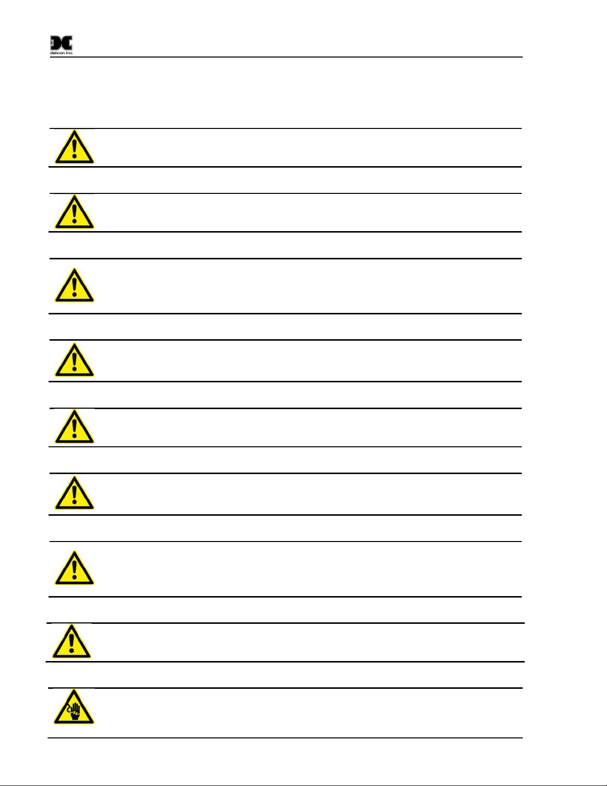
Mechanical Specifications
Dimensions: 12" W x 21.3" H x 4.73" D (including antenna and strobe)
12" W x 12.25" H x 4.73 D (without antenna and strobe)
Wireless Specifications
Frequency: ISM 2.4GHz
Range: Indoor/No Line of Sight – 1,000ft
Outdoor RF Line of Sight – 1.5 Miles
Spread Spectrum: Digital-Sequence Spread Spectrum (DSSS)
Modulation: 0-QPSK
Sensitivity: -102dBm (1% PER)
Sentinel CX Sensor Station IM Rev. 1.4 Page 24 of 26
Page 29

9.2 Spare Parts and Wireless Accessories
Part Number Spare Parts
976-0003BC-00T CXT Battery Charger Accessory for 110 VAC
976-0003BC-220 CXT Battery Charger Accessory for 220 VAC
976-0003A4-200 Antenna Assembly
960-798434-000 Condensation Prevention Packet (replace annually)
894-7845K6-400 Hole Plug
500-005199-000 Relay Board
500-005194-000 Sensor Input Board
360-3S6PFP-ASM Battery Pack
320-N45161-000 Power Switch
302-RSFCC0-05M Connector Dust Cap
302-RFK40D-05M Sensor Connector
302-RFK380-05M Power Connector
302-RFK520-05M External Alarm Connector for ‘Wet’ Relay Contacts
302-PRSF63-M20 External Alarm Connector for ‘Dry’ Relay Contacts
275-556160-432 Power LED Indicator
976-001320-CHR Radio Module (320 Network)
Part Number Accessories
975-TRIPOD-100 Detcon tripod
943-004413-000 Detcon Tripod sensor brackets
975-TRIPOD-MNI Mini Sensor Tripod
980-PRSM40-02M 2m Sensor Cable (with security clip)
980-PRSM40-10M 10m Sensor Cable (with security clip)
980-PRSM40-30M 30m Sensor Cable (with security clip)
980-PRSM40-45M 45m Sensor Cable (with security clip)
980-PRSM52-02M 2m External Alarm Cable for ‘Wet’ Alarms (with security clip)
980-PRSM52-30M 30m External Alarm Cable for ‘Wet’ Alarms (with security clip)
980-PRSM52-45M 45m External Alarm Cable for ‘Wet’ Alarms (with security clip)
980-PRKM63-30M 30m External Alarm Cable for ‘Dry’ Alarms (with security clip)
980-PRKM63-45M 45m External Alarm Cable for ‘Dry’ Alarms (with security clip)
Sentinel CX
Sentinel CX Sensor Station IM Rev. 1.4 Page 25 of 26
Page 30

Sentinel CX
9.3 Revision Log
Revision Date Changes made Approval
1.0 03/27/2013 Release LBU
1.1 10/30/13 Update for removable battery pack LBU
1.2 11/20/13 Updates for Approval Agency BM
1.3 04/04/14 Updates to sensor wiring, and battery charging BM
1.4 05/30/14 Various corrections, clarifications and addition of final Warnings BM
Shipping Address: 4055 Technology Forest Blvd., The Woodlands Texas77381
Mailing Address: P.O. Box 8067, The Woodlands Texas 77387-8067
Phone: 713.559.9200 • Fax: 281.292.2860 • www.detcon.com • sales@detcon.com
Sentinel CX Sensor Station IM Rev. 1.4 Page 26 of 26
Page 31
3
REV
4409-1
DRAWING NO.
A
SIZENAJOB NO.
Antenna
Alarm Port
Power-In
Port
Power Switch
Power
Switch
Strobe
Power LED
Enclosure Label
12
Serial Number
Name Plate
Sonalert
10.25
11.25
Sonalert
21.275
12.25
2~3" Pole Mounting
Hardware
Sensor
Ports
P.O. NO.
REQ. NO.
PROJECT NO.
SERIAL NO.
PLANT:
The information and technical data disclosed by
NA
this document may be used and disseminated
only for the purposes and to the extent
NA
specifically authorized by Detcon Incorporated
in writing. Such information and technical data
are proprietary to Detcon Incorporated and may
NA
not be used or disseminated except as provided
in the foregoing sentence.
NA
NA
NOTE:
Unit shown has the max options:
Power Input Port
4 sensor ports
Alarm Output connector
Strobe and Sonalert Horn
All dimensions are in inches
detcon, inc.
CLIENT:
ECO-1830
ECO-1808
ECO-1753
RELEASE
SUBJECT
PROJECT:
NA
DRAWN BY:
R HUTSKO
FIRST ISSUE:
3
2
1
0
Rev
ADD EPOXY TO HORN THREADS
04/01/14
10/08/13
MAKE BATTERY PACK REMOVABLE
07/26/13
01/21/13
DATE
CHANGE ENCLOSURE
ISSUED FOR APPROVAL
REVISION HISTORY
DESCRIPTION
RH
DRN
RH
RH
RH
CHKD
4409
LU
BM
4409
BM
LU
4409
LU
BM
4409
LU
BM
APPD
DWG #
REF. DWGS
DETCON INC.
4055 Technology Forest Bvd. Suite 100 * The Woodlands Texas 77381 * www.detcon.com
NA
01/21/13
_
Sentinel w Solid Cover
Dimensional
P/N 954-CX04y4-200
SCALE
SALES ORDER NO.
NTS
NA
DETCON PRPOSAL #
NA
DRAWING NO.
4409-1
REV
SIZE
A
3
Page 32
External Alarm
3
REV
4409-2
DRAWING NO.
A
SIZE
JOB NO.
NA
PLANT:
NANANA
REVISION HISTORY
REF. DWGS
REQ. NO.
SERIAL NO.
in the foregoing sentence.
Rev
DATE
DESCRIPTION
DRN
CHKD
APPD
DWG #
P.O. NO.
PROJECT NO.
NA
NA
The information and technical data disclosed by
this document may be used and disseminated
only for the purposes and to the extent
specifically authorized by Detcon Incorporated
in writing. Such information and technical data
are proprietary to Detcon Incorporated and may
not be used or disseminated except as provided
1
0
2
3
07/26/13
01/21/13
10/08/13
04/01/14
MAKE BATTERY PACK REMOVABLE
ADD EPOXY TO HORN THREADS
ISSUED FOR APPROVAL
CHANGE ENCLOSURE
RH
RH
RH
RH
LU
LU
LU
LU
BM
BM
BM
BM
4409
4409
4409
4409
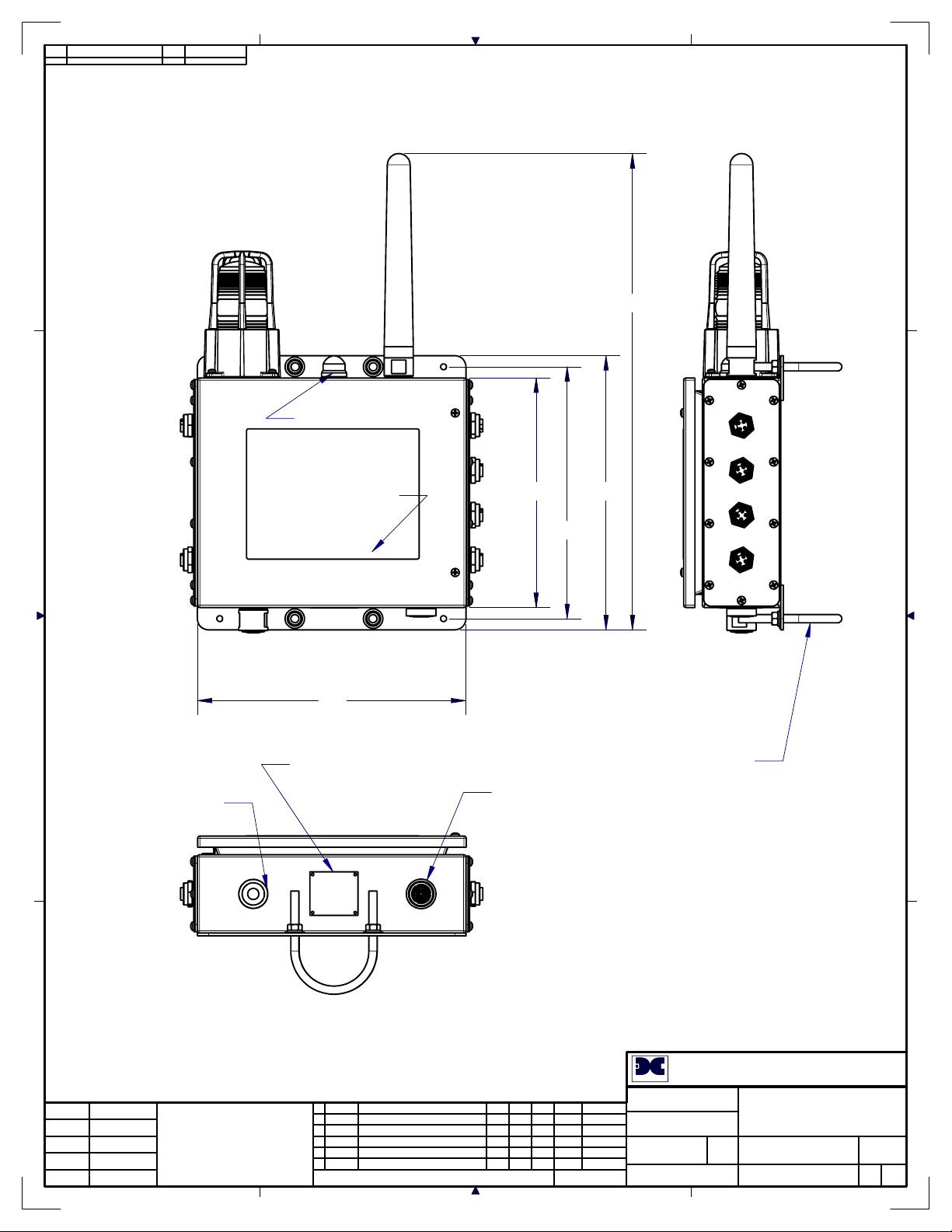
Switch
Power
Sonalert
Connector
Charger
Battery Pack
Connector
RXT-320
Xcvr
Sensor Ports
(Optional)
Strobe
Power LED
Antenna
Sentinel Relay PCA
and 4-20mA PCA
RELEASE
SUBJECT
FIRST ISSUE:
R HUTSKO
01/21/13
NTS
DETCON PRPOSAL #
NA
NA
4409-2
SIZE
A
REV
3
ECO-1753
ECO-1808
ECO-1830
DRAWN BY:
PROJECT:
CLIENT:
NA
SCALE
SALES ORDER NO.
P/N 954-CX04y4-200
detcon, inc.
4055 Technology Forest Bvd. Suite 100 * The Woodlands Texas 77381 * www.detcon.com
NA
_
DETCON INC.
Sentinel w Solid Cover
Overview
DRAWING NO.
NOTE:
Unit shown has the max options:
Power Input Port
4 sensor ports
Alarm Output connector
Strobe and Sonalert Horn
All dimensions are in inches
Cover removed for clarity
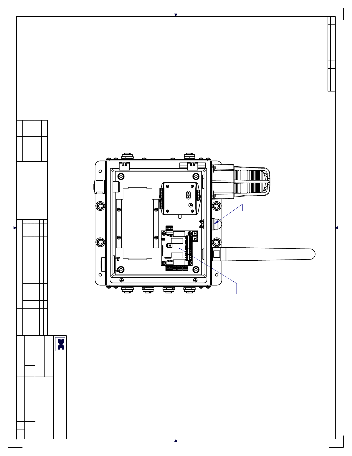
Page 33

4409-3
DRAWING NO.
REV
SIZE
3
A
White
Gray
Brown
Blue
Red
Black
White
Red
Sensor 1
Red
Black
Black
White
Black
Sensor 2
Red
Red
Relay PCA
Black
White
Sensor 3
Red
4-20mA PCA
Sensor 4
Red
Black
White
NOTE:
Green wire from sensor
connectors to be tied to
base plate (Ground).
Black
Red
+ -
(Mounted under the Relay PCA)
Wiring
NA
SALES ORDER NO.
DETCON PRPOSAL #
SCALE
NTS
R HUTSKO
DRAWN BY:
FIRST ISSUE:
ECO-1753
SUBJECT
RELEASE
4409
DWG #
4409
BM
BM
APPD
LU
LU
CHKD
RH
DRN
RH
NA
01/21/13
REF. DWGS
P/N 954-CX04y4-200
Sentinel w Solid Cover
DETCON INC.
_
NA
4055 Technology Forest Bvd. Suite 100 * The Woodlands Texas 77381 * www.detcon.com
CLIENT:
NA
PROJECT:
ECO-1808
ECO-1830
4409
4409
BM
BM
LU
LU
RH
RH
detcon, inc.
Sonalert Horn
DESCRIPTION
CHANGE ENCLOSURE
ISSUED FOR APPROVAL
ADD EPOXY TO HORN THREADS
MAKE BATTERY PACK REMOVABLE
REVISION HISTORY
NA
JOB NO.
SIZE
A
DRAWING NO.
4409-3
REV
3
LED
+
Strobe
Red
Black
Red
Black
White
Brown
Gray
+
To
Red
Color
1502B Cable Wiring
Black
Blue
(Optional)
External Alarm
Black
-
A
B
Blue
Black
White
shown)
Connector
("Wet' alarm wiring
NOTE:
1502B Cable
Red
To
Antenna
RXT-320
Green wire from Power
Input connector to be tied
to base plate (Ground).
Black
Black
White
Power Port
Red
Red
Black
White
Red
Black
Black
Flat Battery Pack
Assembly
Red
Power
Switch
10/08/13
DATE
07/26/13
04/01/14
01/21/13
2
1
3
0
Rev
The information and technical data disclosed by
this document may be used and disseminated
only for the purposes and to the extent
specifically authorized by Detcon Incorporated
in writing. Such information and technical data
are proprietary to Detcon Incorporated and may
not be used or disseminated except as provided
in the foregoing sentence.
NA
NA
NANANA
PROJECT NO.
REQ. NO.
SERIAL NO.
PLANT:
P.O. NO.
 Loading...