

Page 1

detcon inc.
Detcon Model Series
DM-400IS
Explosion Proof and Intrinsically Safe Toxic Gas Sensors
Operator’s Installation & Instruction Manual
November 8, 2010 • Document #2432 • Version 1.5.8
phone 888-367-4286, 281-367-4100 • fax 281-292-2860 • www.detcon.com • sales@detcon.com
Page 2

Table of Contents
3.0 Description
3.1 Principle of Operation
3.2 Application
3.3 Specifications
3.4 Installation
3.5 Start-up
3.6 Calibration
3.7 Trouble Shooting Guide
3.8 Spare Parts List
3.9 Warranty
3.10 Service Policy
DM-400IS Toxic Gas Sensors PG.2
Page 3

This manual covers the following Models...
Model # Gas Name Symbol
DM-400-C2H3O Acetyldehyde C2H3O
DM-400-C2H2 Acetylene C2H2
DM-400-C3H3N Acrylonitrile C3H3N
DM-400-NH3 (-20°C) Ammonia NH3
DM-401-NH3 (-40°C) Ammonia NH3
DM-402-NH3 (
DM-400-AsH3 Arsine AsH3
DM-400-Br2 Bromine Br2
DM-400-C4H6 Butadiene C4H6
DM-400-CS2 Carbon Disulfide CS2
DM-400-CO Carbon Monoxide CO
DM-400-COS Carbonyl Sulfide COS
DM-400-CL2 Chlorine CL2
DM-400-CLO2 (>40 ppm range) Chlorine Dioxide CLO2
DM-401-CLO2 (≤40 ppm range) Chlorine Dioxide CLO2
DM-400-B2H6 Diborane B2H6
DM-400-C2H6S Dimethyl Sulfide C2H6S
DM-400-C3H5OCL Epichlorohydrin C3H5OCL
DM-400-C2H5OH Ethanol C2H5OH
DM-400-C2H5SH Ethyl Mercaptan C2H5SH
DM-400-C2H4 Ethylene C2H4
DM-400-C2H4O Ethylene Oxide C2H4O
DM-400-F2 Fluorine F2
DM-400-CH2O Formaldehyde CH2O
DM-400-GeH4 Germane GeH4
DM-400-N2H4 Hydrazine N2H4
DM-400-H2 (ppm range) Hydrogen H2
DM-401-H2 (% LEL range) Hydrogen H2
DM-400-HBr Hydrogen Bromide HBr
DM-400-HCL Hydrogen Chloride HCL
DM-400-HCN Hydrogen Cyanide HCN
DM-400-HF Hydrogen Fluoride HF
DM-400-H2S Hydrogen Sulfide H2S
DM-400-CH3OH Methanol CH3OH
DM-400-CH3SH Methyl Mercaptan CH3SH
DM-400-NO Nitric Oxide NO
DM-400-NO2 Nitrogen Dioxide NO2
DM-400-O3 Ozone O3
DM-400-COCL2 Phosgene COCL2
DM-400-PH3 Phosphine PH3
DM-400-SiH4 Silane SiH4
DM-400-SO2 Sulfur Dioxide SO2
DM-400-C4H8S Tetrahydrothiophene C4H8S
DM-400-C4H4S Thiophane C4H4S
DM-400-C6H5CH3 Toluene C6H5CH3
DM-400-C4H6O2 Vinyl Acetate C4H6O2
DM-400-C2H3CL Vinyl Chloride C2H3CL
continuous exposure
) Ammonia NH3
DM-400IS Toxic Gas Sensors PG.3
Page 4

3.0 DESCRIPTION
Construction of Electrochemical Sensor
Reference Electrode
Counter Electrode
Electrolyte Reservoir
Sensing Electrode
Diffusion Barrier
Detcon Model series DM-400IS, toxic gas sensors are designed to detect and continuously monitor for toxic gas in the
ppm range. Method of detection is by diffusion/adsorption requiring no moving parts. The sensor assembly consists of
an electrochemical fuel cell mounted in an Intrinsically Safe stainless steel and ABS plastic housing that includes an
integral rain-shield, a universal signal conditioning control transmitter circuit, a base connector board and an explosion
proof junction box.
Typical ranges of detection are 0-10ppm, 0-25ppm, 0-50ppm and 0-100ppm. Other ranges are available and all ranges are covered by this manual. To find out the specific gas type and range of detection of your sensor(s), refer to the label located on
the stainless steel sensor housing.
3.0.1 Sensor Technology
The sensors are electrolytic chemical cells. Each cell consists of three electrodes embedded in an electrolyte solution all
housed beneath a diffusion membrane. Sensitivity to specific target gases is achieved by varying composition of any
combination of the sensor components. Good specificity is achieved in each sensor type. The cells are diffusion limited
via small capillary barriers resulting in long service life of up to 3 or more years. The fuel cell is packaged as a field
replaceable plug-in sensor via gold plated pins. Pre-amplifier and intrinsically safe barrier circuits are epoxy potted in the
stainless steel housing and include the mating sockets for the sensor.
DM-400IS Toxic Gas Sensors PG.4
Page 5

3.0.2 Control Transmitter Circuit
T
E
X
A
S
H
O
U
S
T
O
N
SIGNAL
Model DM-4xx
ZERO
FINE
COARSE
Gas Sensor
detcon inc.
UNIVERSAL
TRANSMITTER
0
1
2
3
4
5
6
7
8
9
A
B
C
D
E
Span Adjustments
Plug-in Transmitter Circuit
Signal Test Points
BLK
BLU
YEL
WHT
MA
Sensor
4-20 mA Loop
+VDC
VDC Common
Intrinsically Safe
Sensor Head
Transmitter Electronics
in Explosion-Proof housing
The 4-20 mA DC control transmitter is equipped with zero and span adjustments accessible through a face plate allowing
one man remote calibration without communication with control room personnel. The transmitter circuit module is
plug-in replaceable, via gold plated pins, facilitating easy maintenance and repair.
3.0.3 Base Connector Board
The base connector board is mounted in the explosion proof enclosure and includes: the mating connector for the control circuit, reverse input and secondary transient suppression, input filter and lugless terminals for all field wiring.
3.0.4 Explosion Proof Enclosure
The explosion proof enclosure is a Killark type HKB-GC with 3/4” NPT female entry ports. It’s constructed of cast aluminum and given an epoxy paint finish. The enclosure is fitted with a threaded cover. Electrical classification is Class 1;
Groups B, C, D; Div. 1.
DM-400IS Toxic Gas Sensors PG.5
Page 6

3.1 PRINCIPLE OF OPERATION
Functional
Block
Diagram
4-20 mA +
Sensor
Element
Preamp
I/O Circuit
Protection
4-20 mA –
(11.5-28 VDC)
Transmitter Power
Signal Conditioning
(zero/span)
Method of detection is by an electrochemical reaction at the surface of an electrode called the sensing electrode. Air
and gas diffuse through the capillary diffusion barrier. The controlling circuit maintains a small external operating voltage between the sensing and counter electrodes of the proper bias and magnitude so that no current flows to or from
the reference electrode while its potential is maintained at the correct fixed voltage — usually ground. The electrochemical reaction creates a change in current flow from the counter electrode to the sensing electrode. This change in current
is proportional to the gas concentration and is reversible. The quick response of the sensor results in continuous monitoring of ambient air conditions. The Intrinsically Safe Housing design allows direct contact of the target gas to the
electrochemical sensor, thus maximizing response time, detectability and repeatability.
3.2 APPLICATION
3.2.1 Sensor Placement/Mounting
Sensor location should be reviewed by facility engineering and safety personnel. Area leak sources and perimeter mounting
are typically used to determine number and location of sensors. The sensors are generally located 2 - 4 feet above grade.
3.2.2 Interference Data
Detcon Model DM-400IS series electrochemical sensors are subject to interference from other gases. This interaction is
shown in the table in section 3.2.4 as the relation between the amount of the interfering gas applied to the sensor, and
the corresponding reading that will occur. All measurements are in ppm unless otherwise noted.
The table is laid out with the Model Number of each sensor in a column on the left side of the page. The interfering
gases are listed in a row across the top of the page. Each page lists all Model Numbers but 5 pages are necessary to list
all interfering gases, thus each page is a repeat of the full line of Detcon sensors. Be sure to reference each page to ascertain the full listing of interfering gases for a particular sensor.
As an example, the first listing shows that the Model DM-400IS-C2H30 acetyldehyde sensor will have an interference
reading of 340 ppm if 40 ppm of C2H2 (Acetylene) is applied.
NOTE:
Interference factors may differ from sensor to sensor and with life time. It is not advisable to calibrate with
interference gases. They should be used as a guide only.
3.2.3 Interference Gas List
Gas Name
Symbol
Acetyldehyde C2H3O
Acetylene C2H2
Acrylonitrile C3H3N
Alcohols Alcohols
Amines Amines
Ammonia NH3
Arsenic Triflouride AsF3
Arsenic Pentaflouride AsF5
Arsine AsH3
Boron Triflouride BF3
Bromine Br2
Butadiene C4H6
Buten-1- Buten-1
Carbon Dioxide CO2
DM-400IS Toxic Gas Sensors PG.6
Page 7

Carbon Disulfide CS2
Carbon Oxide Sulfide COS
Carbon Monoxide CO
Carbonyl Sulfide COS
Chlorine CL2
Chlorine Dioxide CLO2
Chlorine Triflouride CLF3
Diborane B2H6
Dimethyl Sulfide C2H6S
Disilane Si2H6
Epichlorohydrin C3H5OCL
Ethanol C2H5OH
Ethyl Mercaptan C2H5SH
Ethylene C2H4
Ethylene Oxide C2H4O
Fluorine F2
Formaldehyde CH2O
Germane GeH4
Hydrazine N2H4
Hydrocarbons C-H’s
Hydrocarbons (unsaturated) C-H’s (u)
Hydrogen H2
Hydrogen Bromide HBr
Hydrogen Chloride HCL
Hydrogen Cyanide HCN
Hydrogen Flouride HF
Hydrogen Selenide HSe
Hydrogen Sulfide H2S
Iodine I2
Isopropanol C3H8O
Methane CH4
Methanol CH3OH
Methyl-ethyl-ketone C4H8O
Methyl Mercaptan CH3SH
Nitric Oxide NO
Nitrogen N2
Nitrogen Dioxide NO2
Ozone O3
Phosgene COCL2
Phosphine PH3
Phosphorous Triflouride PF3
Silane SiH4
Silicon Si
Silicon Tetra Flouride SiF4
Sulfur Dioxide SO2
Tetrahydrothiophene C4H8S
Thiophane C4H4S
Toluene C6H5CH3
Tungsten Hexaflouride WF6
Vinyl Acetate C4H6O2
Vinyl Chloride C2H3CL
DM-400IS Toxic Gas Sensors PG.7
Page 8

3.2.4.1 Interference Gas Table (page 1 of 5)
NOTE:
Reference the listing on page 3 to match model number with gas name. Reference the listing in section 3.3 to
match the interfering gas symbol with the gas name.
Model Number C2H30 C2H2 C3H3N Alcohols Amines NH3 AsF3 AsF5 AsH3 BF3 Br2 C4H6 Buten-1
DM-400IS-C2H3O n/a 40=340 40=75 n/d n/d n/d n/d n/d n/d n/d n/d 40=170 n/d
DM-400IS-C2H2 340=40 n/a 340=75 n/d n/d n/d n/d n/d n/d n/d n/d 340=170 n/d
DM-400IS-C3H3N 75=40 75=340 n/a n/d n/d n/d n/d n/d n/d n/d n/d 75=170 n/d
DM-400IS-NH3 (-20°C) n/d n/d n/d 1000=0 yes n/d n/a n/d n/d 1=0 n/d n/d n/d n/d
DM-401IS-NH3 (-40°C) n/d n/d n/d n/d yes n/d n/d n/d n/d 1=0 n/d n/d n/d n/d
DM-402IS-NH3 (CE) n/d n/d n/d n/d n/d n/d n/d n/d n/d n/d n/d n/d n/d
DM-400IS-AsH3 n/d n/d n/d n/d n/d 100=0.01 n/d n/d n/a n/d n/d n/d n/d
DM-400IS-Br2 n/d n/d n/d n/d n/d n/d n/d n/d n/d n/d n/a n/d n/d
DM-400IS-C4H6 170=40 170=340 170=75 n/d n/d n/d n/d n/d n/d n/d n/d n/a n/d
DM-400IS-CS2 140=40 140=340 140=75 n/d n/d n/d n/d n/d n/d n/d n/d 140=170 n/d
DM-400IS-CO n/d n/d n/d n/d n/d n/d n/d n/d n/d n/d n/d n/d n/d
DM-400IS-COS 135=40 135=340 135=75 n/d n/d n/d n/d n/d n/d n/d n/d 135=170 n/d
DM-400IS-CL2 n/d n/d n/d n/d n/d n/d n/d n/d n/d n/d 1=0.55 n/d n/d
DM-400IS-CLO2 (>10ppm) n/d n/d n/d n/d n/d n/d n/d n/d n/d n/d 1=0.18 n/d n/d
DM-401IS-CLO2 (≤10ppm)n/d n/d n/d n/d n/d n/d n/d n/d n/d n/d n/d n/d n/d
DM-400IS-B2H6 n/d n/d n/d n/d n/d 100=0.013 n/d n/d 0.15=0.2 n/d n/d n/d n/d
DM-400IS-C2H6S 150=40 150=340 150=75 n/d n/d n/d n/d n/d n/d n/d n/d 150=170 n/d
DM-400IS-C3H5OCL 50=40 50=340 50=75 n/d n/d n/d n/d n/d n/d n/d n/d 50=170 n/d
DM-400IS-C2H5OH 180=40 180=340 180=75 n/d n/d n/d n/d n/d n/d n/d n/d 180=170 n/d
DM-400IS-C2H5SH n/d n/d n/d n/d n/d n/d n/d n/d n/d n/d n/d n/d n/d
DM-400IS-C2H4 220=40 220=340 220=75 n/d n/d n/d n/d n/d n/d n/d n/d 220=170 n/d
DM-400IS-C2H4O 275=40 275=340 275=75 n/d n/d n/d n/d n/d n/d n/d n/d 275=170 n/d
DM-400IS-F2 n/d n/d n/d 1000=0 n/d n/d n/d n/d 0.1=0 n/d yes n/d n/d n/d
DM-400IS-CH2O 330=40 330=340 330=75 n/d n/d n/d n/d n/d n/d n/d n/d 330=170 n/d
DM-400IS-GeH4 n/d n/d n/d n/d n/d 100=<1 n/d n/d 0.2=0.14 n/d n/d n/d n/d
DM-400IS-N2H4 n/d n/d n/d 1000=0 n/d 200=0.04 n/d n/d 0.1=0.1 n/d n/d n/d n/d
DM-400IS-H2 (ppm) n/d n/d n/d n/d n/d n/d n/d n/d n/d n/d n/d n/d n/d
DM-401IS-H2 (LEL) n/d n/d n/d n/d n/d 100=0 n/d n/d n/d n/d n/d n/d n/d
DM-400IS-HBr n/d n/d n/d 1000=0 no n/d n/d n/d 0.1=0.3 n/d n/d n/d n/d
DM-400IS-HCL n/d n/d n/d 1000=0 no n/d n/d n/d 0.1=0.3 n/d n/d n/d n/d
DM-400IS-HCN n/d n/d n/d 1000=0 n/d n/d n/d n/d 0.1=0 n/d yes n/d n/d n/d
DM-400IS-HF n/d n/d n/d 1000=0 n/d n/d yes n/d yes n/d 0.1=0 yes n/d n/d n/d n/d
DM-400IS-H2S n/d n/d n/d n/d n/d n/d n/d n/d n/d n/d n/d n/d n/d
DM-400IS-CH3OH 415=40 415=340 415=75 n/d n/d n/d n/d n/d n/d n/d n/d 415=170 n/d
DM-400IS-CH3SH n/d n/d n/d n/d n/d n/d n/d n/d n/d n/d n/d 275=170 n/d
DM-400IS-NO n/d n/d n/d n/d n/d n/d n/d n/d n/d n/d n/d n/d n/d
DM-400IS-NO2 n/d n/d n/d n/d n/d n/d n/d n/d n/d n/d n/d n/d n/d
DM-400IS-O3 n/d n/d n/d n/d n/d n/d n/d n/d 0.1=
DM-400IS-COCL2 n/d n/d n/d 1000=0 n/d 50=0.5 n/d n/d n/d n/d n/d n/d n/d
DM-400IS-PH3 n/d n/d n/d n/d n/d 100=0.01 n/d n/d 1=1 n/d n/d n/d n/d
DM-400IS-SiH4 n/d n/d n/d n/d n/d 100=<1 n/d n/d 0.2=0.14 n/d n/d n/d n/d
DM-400IS-SO2 n/d n/d n/d n/d n/d n/d n/d n/d n/d n/d n/d n/d n/d
DM-400IS-C4H8S n/d n/d n/d n/d n/d n/d n/d n/d n/d n/d n/d n/d n/d
DM-400IS-C4H4S 45=40 45=340 45=75 n/d n/d n/d n/d n/d n/d n/d n/d 45=170 1%=1.8
DM-400IS-C6H5CH3 55=40 55=340 55=75 n/d n/d n/d n/d n/d n/d n/d n/d 55=170 n/d
DM-400IS-C4H6O2 200=40 200=340 200=75 n/d n/d n/d n/d n/d n/d n/d n/d 200=170 n/d
DM-400IS-C2H3CL 200=40 200=340 200=75 n/d n/d n/d n/d n/d n/d n/d n/d 200=170 n/d
n/a = not applicable
n/d = no data
0.05 n/d yes n/d n/d n/d
DM-400IS Toxic Gas Sensors PG.8
Page 9

3.2.4.2 Interference Gas Table (page 2 of 5)
Model Number CO2 CS2 CO COS CL2 CLO2 CLF3 B2H6 C2H6S Si2H6 C3H5OCL C2H5OH
DM-400IS-C2H3O n/d 40=140 40=100 40=135 n/d n/d n/d n/d 40=150 n/d 40=50 40=180
DM-400IS-C2H2 n/d 340=140 340=100 340=135 n/d n/d n/d n/d 340=150 n/d 340=50 340=180
DM-400IS-C3H3N n/d 75=140 75=100 75=135 n/d n/d n/d n/d 75=150 n/d 75=50 75=180
DM-400IS-NH3 (-20°C) 5000=0 n/d 1000=0 n/d 1=0 n/d n/d 0.1=0 n/d n/d n/d n/d
DM-401IS-NH3 (-40°C) 5000=0 n/d 300=100 n/d 5=0 n/d n/d 0.1=0 n/d n/d n/d n/d
DM-402IS-NH3 (CE) n/d n/d 300=8 n/d 1=-1 10%=-15 n/d n/d n/d n/d n/d n/d
DM-400IS-AsH3 5000=0 n/d 300=0 n/d 0.5=–0.04 n/d n/d 0.2=0.15 n/d 5=yes n/d n/d n/d
DM-400IS-Br2 n/d n/d 300=0 n/d 1=2 1=6 n/d n/d n/d n/d n/d n/d
DM-400IS-C4H6 n/d 170=140 170=100 170=135 n/d n/d n/d n/d 170=150 n/d 170=50 170=180
DM-400IS-CS2 n/d n/a 140=100 140=135 n/d n/d n/d n/d 140=150 n/d 140=50 140=180
DM-400IS-CO n/d n/d n/a n/d 1=0 n/d n/d n/d n/d n/d n/d 200=0
DM-400IS-COS n/d 135=140 135=100 n/a n/d n/d n/d n/d 135=150 n/d 135=50 135=180
DM-400IS-CL2 n/d n/d 300=0 n/d n/a n/d n/d n/d n/d n/d n/d n/d
DM-400IS-CLO2 (>10ppm) n/d n/d 300=0 n/d 3=1 n/a n/d n/d n/d n/d n/d n/d
DM-401IS-CLO2 (≤10ppm)5000=0 n/d 1000=0 n/d 1=0.9 n/a yes n/d 0.1=0 n/d n/d n/d n/d
DM-400IS-B2H6 5000=0 n/d 300=0 n/d 0.5=–0.05 n/d n/d n/a n/d 5=yes n/d n/d n/d
DM-400IS-C2H6S n/d 150=140 150=100 150=135 n/d n/d n/d n/d n/a n/d 150=50 150=180
DM-400IS-C3H5OCL n/d 50=140 50=100 50=135 n/d n/d n/d n/d 50=150 n/d n/a 50=180
DM-400IS-C2H5OH n/d 180=140 180=100 180=135 n/d n/d n/d n/d 180=150 n/d 180=50 n/a
DM-400IS-C2H5SH n/d n/d 300≤5 n/d 1=-0.6 n/d n/d n/d n/d n/d n/d n/d
DM-400IS-C2H4 n/d 220=140 220=100 220=135 n/d n/d n/d n/d 220=150 n/d 220=50 220=180
DM-400IS-C2H4O n/d 275=140 275=100 275=135 n/d n/d n/d n/d 275=150 n/d 275=50 275=180
DM-400IS-F2 5000=0 n/d 1000=0 n/d 1=1.3 n/d n/d n/d n/d n/d n/d n/d
DM-400IS-CH2O n/d 330=140 330=100 330=135 n/d n/d n/d n/d 330=150 n/d 330=50 330=180
DM-400IS-GeH4 5000=0 n/d 300=0 n/d 0.5=–0.04 n/d n/d 0.2=0.11 n/d 5=yes n/d n/d n/d
DM-400IS-N2H4 5000=0 n/d 1000=0 n/d 1=0 n/d n/d n/d n/d n/d n/d n/d
DM-400IS-H2 (ppm) n/d n/d 300=<30 n/d 1=0 n/d n/d n/d n/d n/d n/d n/d
DM-401IS-H2 (LEL) 1000=0 n/d 50=6 n/d 5=0 n/d n/d n/d n/d n/d n/d n/d
DM-400IS-HBr 5000=0 n/d 1000=0 n/d 5=1 n/d yes n/d n/d n/d n/d n/d n/d
DM-400IS-HCL 5000=0 n/d 1000=0 n/d 5=1 n/d 1=yes n/d n/d n/d n/d n/d n/d
DM-400IS-HCN 5000=0 n/d 1000=0 n/d 5=–1 n/d n/d n/d n/d n/d n/d n/d
DM-400IS-HF 5000=0 n/d 1000=0 n/d 1=0.4 n/d yes n/d 0.1=0 n/d n/d n/d n/d
DM-400IS-H2S n/d n/d 300=≤1.5 n/d 1=≈–0.2 n/d n/d n/d n/d n/d n/d n/d
DM-400IS-CH3OH n/d 415=140 415=100 415=135 n/d n/d n/d n/d 415=150 n/d 415=50 415=180
DM-400IS-CH3SH n/d n/d 300≤3 n/d 1=-0.4 n/d n/d n/d n/d n/d n/d n/d
DM-400IS-NO n/d n/d 300=0 n/d 1=0 n/d n/d n/d n/d n/d n/d n/d
DM-400IS-NO2 n/d n/d 300=0 n/d 1=≈1 n/d n/d n/d n/d n/d n/d n/d
DM-400IS-O3 5000=0 n/d 300=0 n/d 1=1.4 0.1=0.12 1=1(theor.) n/d n/d n/d n/d n/d
DM-400IS-COCL2 5000=0 n/d 1000=0 n/d 1=0 n/d n/d n/d n/d n/d n/d n/d
DM-400IS-PH3 5000=0 n/d 300=0 n/d 0.5=–0.04 n/d n/d 0.2=0.15 n/d 5=yes n/d n/d n/d
DM-400IS-SiH4 5000=0 n/d 300=0 n/d 0.5=–0.04 n/d n/d 0.2=0.11 n/d 5=yes n/d n/d n/d
DM-400IS-SO2 n/d n/d 300=<5 n/d 1=<
DM-400IS-C4H8S 5000=0 n/d 0.1%=1.2 1%=10 n/d n/d n/d n/d n/d n/d n/d n/d
DM-400IS-C4H4S n/d 45=140 45=100 45=135 n/d n/d n/d n/d 45=150 n/d 45=50 45=180
DM-400IS-C6H5CH3 n/d 55=140 55=100 55=135 n/d n/d n/d n/d 55=150 n/d 55=50 55=180
DM-400IS-C4H6O2 n/d 200=140 200=100 200=135 n/d n/d n/d n/d 200=150 n/d 200=50 200=180
DM-400IS-C2H3CL n/d 200=140 200=100 200=135 n/d n/d n/d n/d 200=150 n/d 200=50 200=180
n/a = not applicable
n/d = no data
0.5 n/d n/d n/d n/d n/d n/d n/d
DM-400IS Toxic Gas Sensors PG.9
Page 10

3.2.4.3 Interference Gas Table (page 3 of 5)
Model Number C2H4 C2H4O F2 CH2O GeH4 N2H4 C-H’s C-H’s (U) H2 HBr HCL HCN HF
DM-400IS-C2H3O 40=220 40=275 n/d 40=330 n/d n/d n/d n/d n/d n/d n/d n/d n/d
DM-400IS-C2H2 340=220 340=275 n/d 340=330 n/d n/d n/d n/d n/d n/d n/d n/d n/d
DM-400IS-C3H3N 75=220 75=275 n/d 75=330 n/d n/d n/d n/d n/d n/d n/d n/d n/d
DM-400IS-NH3 (-20°C) n/d n/d n/d n/d 1=0 n/d %range=0 n/d 1%=0 n/d 5=0 10=0 4=0
DM-401IS-NH3 (-40°C) n/d n/d n/d n/d 1=0 n/d %range=0 yes n/d 1000=35 n/d yes n/d 10=-18 n/d
DM-402IS-NH3 (CE) 100=0 n/d n/d n/d n/d n/d n/d n/d 200=4 n/d 5=-3 10=0 n/d
DM-400IS-AsH3 n/d n/d n/d n/d 1=0.4 n/d %range=0 n/d 3000=0 n/d 5=0 10=0.1 4=0
DM-400IS-Br2 100=0 n/d n/d n/d n/d n/d n/d n/d 100=0 n/d 5=0 10=0 n/d
DM-400IS-C4H6 170=220 170=275 n/d 170=330 n/d n/d n/d n/d n/d n/d n/d n/d n/d
DM-400IS-CS2 140=220 140=275 n/d 140=330 n/d n/d n/d n/d n/d n/d n/d n/d n/d
DM-400IS-CO 100=<100 n/d n/d n/d n/d n/d n/d n/d 100=<60 n/d 5=0 10=<2 n/d
DM-400IS-COS 135=220 135=275 n/d 135=330 n/d n/d n/d n/d n/d n/d n/d n/d n/d
DM-400IS-CL2 100=0 n/d n/d n/d n/d n/d n/d n/d 100=0 n/d 5=0 10=0 n/d
DM-400IS-CLO2 (>10ppm) 100=0 n/d n/d n/d n/d n/d n/d n/d 100=0 n/d 5=0 10=0 n/d
DM-401IS-CLO2 (≤10ppm)n/d n/d yes n/d n/d 1=0 n/d %range=0 n/d 1%=0 n/d n/d n/d n/d
DM-400IS-B2H6 n/d n/d n/d n/d 1=0.53 n/d %range=0 n/d 3000=0 n/d 5=0 10=0.13 4=0
DM-400IS-C2H6S 150=220 150=275 n/d 150=330 n/d n/d n/d n/d n/d n/d n/d n/d n/d
DM-400IS-C3H5OCL 50=220 50=275 n/d 50=330 n/d n/d n/d n/d n/d n/d n/d n/d n/d
DM-400IS-C2H5OH 180=220 180=275 n/d 180=330 n/d n/d n/d n/d n/d n/d n/d n/d n/d
DM-400IS-C2H5SH 100=0 n/d n/d n/d n/d n/d n/d n/d 1%=<15 n/d 5=0 10=0 n/d
DM-400IS-C2H4 n/a 220=275 n/d 220=330 n/d n/d n/d n/d n/d n/d n/d n/d n/d
DM-400IS-C2H4O 275=220 n/a n/d 275=330 n/d n/d n/d n/d n/d n/d n/d n/d n/d
DM-400IS-F2 n/d n/d n/a n/d n/d n/d %range=0 n/d 1%=0 n/d 5=0 1=–3 3=0
DM-400IS-CH2O 330=220 330=275 n/d n/a n/d n/d n/d n/d n/d n/d n/d n/d n/d
DM-400IS-GeH4 n/d n/d n/d n/d n/a n/d %range=0 n/d 3000=0 n/d 5=0 10=1 4=0
DM-400IS-N2H4 n/d n/d n/d n/d n/d n/a %range=0 n/d 1000=0 n/d 5=0.1 n/d 3=0
DM-400IS-H2 (ppm) 100=≈80 n/d n/d n/d n/d n/d n/d n/d n/a n/d 5=0 10=≈3 n/d
DM-401IS-H2 (LEL) yes n/d n/d n/d n/d n/d n/d n/d n/d n/a n/d n/d 10=0 n/d
DM-400IS-HBr n/d n/d n/d n/d n/d n/d %range=0 n/d 1%=0 n/a 1=1 15=1 3=0
DM-400IS-HCL n/d n/d n/d n/d 1=n/d n/d %range=0 n/d 1%=0 1=1 n/a 15=1 3=0
DM-400IS-HCN n/d n/d n/d n/d n/d n/d %range=0 n/d 1000=0 n/d 5=0 n/a 3=0
DM-400IS-HF n/d n/d yes n/d n/d 1=0 n/d %range=0 n/d 1%=0 n/d 5=3.3 n/d n/a
DM-400IS-H2S 100=0 n/d n/d n/d n/d n/d n/d n/d 1%=<5 n/d 5=0 10=0 n/d
DM-400IS-CH3OH 415=220 415=275 n/d 415=330 n/d n/d n/d n/d n/d n/d n/d n/d n/d
DM-400IS-CH3SH 100=0 n/d n/d n/d n/d n/d n/d n/d 1%=<10 n/d 5=0 10=0 n/d
DM-400IS-NO 100=0 n/d n/d n/d n/d n/d n/d n/d 100=0 n/d 5=<1 10=0 n/d
DM-400IS-NO2 100=0 n/d n/d n/d n/d n/d n/d n/d 100=0 n/d 5=0 10=0 n/d
DM-400IS-O3 n/d n/d 0.1=0.07 n/d n/d n/d n/d n/d 1%=
DM-400IS-COCL2 n/d n/d n/d n/d n/d n/d %range=0 n/d 1%=0 n/d 5=0 5=0 3=0
DM-400IS-PH3 n/d n/d n/d n/d 1=0.4 n/d %range=0 n/d 3000=0 n/d 5=0 10=0.1 4=0
DM-400IS-SiH4 n/d n/d n/d n/d 1=1.0 n/d %range=0 n/d 3000-=0 n/d 5=0 10=1 4=0
DM-400IS-SO2 100=0 n/d n/d n/d n/d n/d n/d n/d 100=0 n/d 5=0 10=<5 n/d
DM-400IS-C4H8S 1%=2.4 n/d n/d n/d n/d n/d %range=0 yes n/d 0.1%=0.3 n/d yes n/d n/d n/d
DM-400IS-C4H4S 45=220 45=275 n/d 45=330 n/d n/d n/d n/d n/d n/d n/d n/d n/d
DM-400IS-C6H5CH3 55=220 55=275 n/d 55=330 n/d n/d n/d n/d n/d n/d n/d n/d n/d
DM-400IS-C4H6O2 200=220 200=275 n/d 200=330 n/d n/d n/d n/d n/d n/d n/d n/d n/d
DM-400IS-C2H3CL 200=220 200=275 n/d 200=330 n/d n/d n/d n/d n/d n/d n/d n/d n/d
n/a = not applicable
n/d = no data
0.003 n/d 10=0 10= 0.03 5=0
DM-400IS Toxic Gas Sensors PG.10
Page 11

3.2.4.4 Interference Gas Table (page 4 of 5)
Model Number HSe H2S I2 C3H8O CH4 CH3OH C4H8O CH3SH NO N2 NO2 O3 COCL2
DM-400IS-C2H3O n/d n/d n/d n/d n/d 40=415 n/d 40=275 n/d n/d n/d n/d n/d
DM-400IS-C2H2 n/d n/d n/d n/d n/d 340=415 n/d 340=275 n/d n/d n/d n/d n/d
DM-400IS-C3H3N n/d n/d n/d n/d n/d 75=415 n/d 75=275 n/d n/d n/d n/d n/d
DM-400IS-NH3 (-20°C) 0.1=0 10=0 n/d n/d n/d n/d n/d n/d n/d 100%=0 n/d n/d n/d
DM-401IS-NH3 (-40°C) n/d 14=18 n/d n/d n/d yes n/d n/d n/d n/d 100%=0 10=-5 n/d n/d
DM-402IS-NH3 (CE) n/d 15=30 n/d n/d n/d n/d n/d n/d 35=6 n/d 5=-1 n/d n/d
DM-400IS-AsH3
DM-400IS-Br2 n/d 15=–1.5 n/d n/d n/d n/d n/d n/d 35=0 n/d 5=≈10 n/d n/d
DM-400IS-C4H6 n/d n/d n/d n/d n/d 170=415 n/d 170=275 n/d n/d n/d n/d n/d
DM-400IS-CS2 n/d n/d n/d n/d n/d 140=415 n/d 140=275 n/d n/d n/d n/d n/d
DM-400IS-CO n/d 15=<0.3 n/d n/d n/d n/d n/d n/d 35=≤7 n/d 5=
DM-400IS-COS n/d n/d n/d n/d n/d 135=415 n/d 135=275 n/d n/d n/d n/d n/d
DM-400IS-CL2 n/d 15=–0.75 n/d n/d n/d n/d n/d n/d 35=0 n/d 5=≈5 n/d n/d
DM-400IS-CLO2 (>10ppm) n/d 15=0.25 n/d n/d n/d n/d n/d n/d 35=0 n/d 5=1.66 n/d n/d
DM-401IS-CLO2 (≤10ppm)n/d 10=-0.015 n/d n/d n/d n/d n/d n/d n/d n/d yes n/d yes n/d n/d
DM-400IS-B2H6 0.05=0.006 1=0 n/d n/d n/d n/d n/d n/d n/d 100%=0 n/d n/d n/d
DM-400IS-C2H6S n/d n/d n/d n/d n/d 150=415 n/d 1:15 n/d n/d n/d n/d n/d
DM-400IS-C3H5OCL n/d n/d n/d n/d n/d 50=415 n/d 50=275 n/d n/d n/d n/d n/d
DM-400IS-C2H5OH n/d n/d n/d n/d n/d 180=415 n/d 180=275 n/d n/d n/d n/d n/d
DM-400IS-C2H5SH n/d 1:3 n/d n/d n/d n/d n/d 5=8 35=<6 n/d 5=-1.5 n/d n/d
DM-400IS-C2H4 n/d n/d n/d n/d n/d 220=415 n/d 220=275 n/d n/d n/d n/d n/d
DM-400IS-C2H4O n/d n/d n/d n/d n/d 275=415 n/d 275=275 n/d n/d n/d n/d n/d
DM-400IS-F2 n/d 1=–1.5 n/d n/d n/d n/d n/d n/d n/d 100%=0 1=0.05 0.1=0.2 n/d
DM-400IS-CH2O n/d n/d n/d n/d n/d 330=415 n/d 330=275 n/d n/d n/d n/d n/d
DM-400IS-GeH4 0.05=0.005 1=0 n/d n/d n/d n/d n/d n/d n/d 100%=0 n/d n/d n/d
DM-400IS-N2H4 n/d 1=0.1 n/d n/d n/d n/d n/d n/d n/d 100%=0 1=–0.25 0.1=–0.1 n/d
DM-400IS-H2 (ppm) n/d 15=<3 n/d n/d n/d n/d n/d n/d 35=≈10 n/d 5=0 n/d n/d
DM-401IS-H2 (LEL) n/d n/d n/d yes n/d 1%=0 n/d n/d n/d yes n/d n/d 10=0 n/d n/d
DM-400IS-HBr 0.1=0 10=2.75 n/d n/d n/d n/d n/d n/d n/d 100%=0 n/d n/d 0.1=0
DM-400IS-HCL 0.1=0 10=2.75 n/d n/d n/d n/d n/d n/d n/d 100%=0 n/d n/d 0.1=0
DM-400IS-HCN n/d 10=0 n/d n/d n/d n/d n/d n/d n/d 100%=0 10=–12 0.1=0 n/d
DM-400IS-HF n/d 10=0 n/d n/d n/d n/d n/d n/d n/d 100%=0 10≈0.1 n/d n/d
DM-400IS-H2S n/d n/a n/d n/d n/d n/d n/d 2:1 35=<2 n/d 5=-0.5 n/d n/d
DM-400IS-CH3OH n/d n/d n/d n/d n/d n/a n/d 415=275 n/d n/d n/d n/d n/d
DM-400IS-CH3SH n/d 1:2 n/d n/d n/d n/d n/d n/a 35=<4 n/d 5=-1.0 n/d n/d
DM-400IS-NO n/d 15=≈5 n/d n/d n/d n/d n/d n/d 100=0 n/d 5=<1.5 n/d n/d
DM-400IS-NO2 n/d 15=
DM-400IS-O3 n/d 1=–.015 yes n/d n/d n/d n/d n/d n/d 10=0 100%=0 1=0.7 n/a n/d
DM-400IS-COCL2 n/d 1=0 n/d n/d n/d n/d n/d n/d n/d 100%=0 n/d n/d n/a
DM-400IS-PH3 0.05=0.005 1=0 n/d n/d n/d n/d n/d n/d n/d 100%=0 n/d n/d n/d
DM-400IS-SiH4
DM-400IS-SO2 n/d 15=0 n/d n/d n/d n/d n/d n/d 35=0 n/d 5=≈–5 n/d n/d
DM-400IS-C4H8S n/d 20=0.3 n/d n/d 100%=0 1300=64 n/d n/d 10=7.5 100%=0 10=
DM-400IS-C4H4S n/d n/d n/d n/d n/d 45=415 n/d 45=275 n/d n/d n/d n/d n/d
DM-400IS-C6H5CH3 n/d n/d n/d n/d n/d 55=415 n/d 55=275 n/d n/d n/d n/d n/d
DM-400IS-C4H6O2 n/d n/d n/d n/d n/d 200=415 n/d 200=275 n/d n/d n/d n/d n/d
DM-400IS-C2H3CL n/d n/d n/d n/d n/d 200=415 n/d 200=275 n/d n/d n/d n/d n/d
n/a = not applicable
n/d = no data
0.05=0.005
0.05=0.005
1=0 n/d n/d n/d n/d n/d n/d n/d 100%=0 n/d n/d n/d
0.5 n/d n/d
–0.75 n/d n/d n/d n/d n/d n/d 35=0 n/d n/a n/d n/d
1=0 n/d n/d n/d n/d n/d n/d n/d 100%=0 n/d n/d n/d
0.9 n/d n/d
DM-400IS Toxic Gas Sensors PG.11
Page 12

3.2.4.5 Interference Gas Table (page 5 of 5)
Model Number PH3 PF3 SiH4 Si SiF4 SO2 C4H8S C4H4S C6H5CH3 WF6 C4H6O2 C2H3CL C2H5SH C6H5CH3
DM-400IS-C2H3O n/d n/d n/d n/d n/d n/d n/d 40=45 n/d n/d 40=200 40=200 n/d 40=55
DM-400IS-C2H2 n/d n/d n/d n/d n/d n/d n/d 340=45 n/d n/d 340=200 340=200 n/d 340=55
DM-400IS-C3H3N n/d n/d n/d n/d n/d n/d n/d 75=45 n/d n/d 75=200 75=200 n/d 75=55
DM-400IS-NH3 (-20°C) 300=0 n/d n/d n/d n/d 2=0 n/d n/d n/d n/d n/d n/d n/d n/d
DM-401IS-NH3 (-40°C) 0.3=0 n/d n/d n/d n/d yes n/d n/d n/d n/d n/d n/d n/d n/d n/d
DM-402IS-NH3 (CE) n/d n/d n/d n/d n/d 5=-0.5 n/d n/d n/d n/d n/d n/d n/d n/d
DM-400IS-AsH3 0.1=0.11 n/d 1=0.56 n/d n/d 2=0 n/d n/d n/d n/d n/d n/d n/d n/d
DM-400IS-Br2 n/d n/d n/d n/d n/d 5=–0.1 n/d n/d n/d n/d n/d n/d n/d n/d
DM-400IS-C4H6 n/d n/d n/d n/d n/d n/d n/d 170=45 n/d n/d 170=200 170=200 n/d 170=55
DM-400IS-CS2 n/d n/d n/d n/d n/d n/d n/d 140=45 n/d n/d 140=200 140=200 n/d 140=55
DM-400IS-CO n/d n/d n/d n/d n/d 5=0 n/d n/d n/d n/d n/d n/d n/d n/d DM400IS-COS n/d n/d n/d n/d n/d n/d n/d 135=45 n/d n/d 135=200 135=200 n/d 135=55
DM-400IS-CL2 n/d n/d n/d n/d n/d 5=–0.05 n/d n/d n/d n/d n/d n/d n/d n/d
DM-400IS-CLO2 (>10ppm) n/d n/d n/d n/d n/d 5=–0.016 n/d n/d n/d n/d n/d n/d n/d n/d
DM-401IS-CLO2 (≤10ppm)n/d n/d n/d n/d n/d n/d n/d n/d n/d n/d n/d n/d n/d n/d
DM-400IS-B2H6 0.1=0.14 n/d 1=0.72 n/d n/d 2=0 n/d n/d n/d n/d n/d n/d n/d n/d
DM-400IS-C2H6S n/d n/d n/d n/d n/d n/d n/d 150=45 n/d n/d 150=200 150=200 n/d 150=55
DM-400IS-C3H5OCL n/d n/d n/d n/d n/d n/d n/d 50=45 n/d n/d 50=200 50=200 n/d 50=55
DM-400IS-C2H5OH n/d n/d n/d n/d n/d n/d n/d 180=45 n/d n/d 180=200 180=200 n/d 180=55
DM-400IS-C2H5SH n/d n/d n/d n/d n/d 5=<3 n/d n/d n/d n/d n/d n/d n/a n/d
DM-400IS-C2H4 n/d n/d n/d n/d n/d n/d n/d 220=45 n/d n/d 220=200 220=200 n/d 220=55
DM-400IS-C2H4O n/d n/d n/d n/d n/d n/d n/d 275=45 n/d n/d 275=200 275=200 n/d 275=55
DM-400IS-F2 n/d n/d n/d n/d n/d 2=0 n/d n/d n/d n/d n/d n/d n/d n/d
DM-400IS-CH2O n/d n/d n/d n/d n/d n/d n/d 330=45 n/d n/d 330=200 330=200 n/d 330=55
DM-400IS-GeH4 0.1=0.13 n/d 1=1 n/d n/d 2=0 n/d n/d n/d n/d n/d n/d n/d n/d
DM-400IS-N2H4 0.3=0.1 n/d n/d n/d n/d 2=0 n/d n/d n/d n/d n/d n/d n/d n/d
DM-400IS-H2 (ppm) n/d n/d n/d n/d n/d 5=0 n/d n/d n/d n/d n/d n/d n/d n/d
DM-401IS-H2 (LEL) n/d n/d n/d n/d n/d 2=0 n/d n/d n/d n/d n/d n/d n/d n/d
DM-400IS-HBr 0.1=0.3 n/d n/d n/d n/d 5=2.5 n/d n/d n/d n/d n/d n/d n/d n/d
DM-400IS-HCL 0.1=0.3 n/d n/d n/d n/d 5=2.5 n/d n/d n/d n/d n/d n/d n/d n/d
DM-400IS-HCN 0.3=0 n/d n/d n/d n/d 2=0 n/d n/d n/d n/d n/d n/d n/d n/d
DM-400IS-HF 0.1=0 yes n/d n/d n/d 3=4(theor.) yes n/d n/d n/d n/d yes n/d n/d n/d n/d n/d
DM-400IS-H2S n/d n/d n/d n/d n/d 5=<1 n/d n/d n/d n/d n/d n/d 3=1 n/d
DM-400IS-CH3OH n/d n/d n/d n/d n/d n/d n/d 415=45 n/d n/d 415=200 415=200 n/d 413=55
DM-400IS-CH3SH n/d n/d n/d n/d n/d 5=<2 n/d n/d n/d n/d n/d n/d 2=1 n/d
DM-400IS-NO n/d n/d n/d n/d n/d 5=0 n/d n/d n/d n/d n/d n/d n/d n/d
DM-400IS-NO2 n/d n/d n/d n/d n/d 5=
DM-400IS-O3 0.3= 0.03 n/d 1= 0.015 n/d n/d 2=0 n/d n/d n/d n/d n/d n/d n/d n/d
DM-400IS-COCL2 0.3=0 n/d n/d n/d n/d 2=0 n/d n/d n/d n/d n/d n/d n/d n/d
DM-400IS-PH3 n/a n/d 1=0.56 n/d n/d 2=0 n/d n/d n/d n/d n/d n/d n/d n/d
DM-400IS-SiH4 0.1=0.13 n/d n/a n/d n/d 2=0 n/d n/d n/d n/d n/d n/d n/d n/d
DM-400IS-SO2 n/d n/d n/d n/d n/d n/a n/d n/d n/d n/d n/d n/d n/d n/d
DM-400IS-C4H8S n/d n/d n/d n/d n/d 2=0.6 n/a n/d n/d n/d n/d n/d n/d n/d
DM-400IS-C4H4S n/d n/d n/d n/d n/d n/d n/d n/a n/d n/d 45=200 45=200 n/d 45=55
DM-400IS-C6H5CH3 n/d n/d n/d n/d n/d n/d n/d 55=45 n/d n/d 55=200 n/d n/d n/a
DM-400IS-C4H6O2 n/d n/d n/d n/d n/d n/d n/d 200=45 n/d n/d n/a 200=200 n/d 200=55
DM-400IS-C2H3CL n/d n/d n/d n/d n/d n/d n/d 200=45 n/d n/d 200=200 n/a n/d 200=55
n/a = not applicable
n/d = no data
–0.025 n/d n/d n/d n/d n/d n/d n/d n/d
DM-400IS Toxic Gas Sensors PG.12
Page 13

3.3 SPECIFICATIONS
Method of Detection
Electrochemical Cell
Electrical Classification
CSA-NRTL (US OSHA) approved* Class 1; Groups B, C, D; Div. 1.
Field Wiring
2 conductor; max 10 ohms single conductor resistance
Input Voltage
11.5-28 VDC
Power Consumption
Normal operation = 4 mA (0.1 watts @ 24VDC); Maximum = 20 mA (0.5 watts @ 24VDC; 0.23 watts @ 11.5VDC)
Output
Linear 4-20 mA DC
Repeatability
± 2% FS
Model Number
DM-400IS-C2H3O Acetyldehyde T90 <140 <5% signal loss/year -20 to +50 -4 to +122 15 to 90 2 years
DM-400IS-C2H2 Acetylene T90 <140 <5% signal loss/year -20 to +50 -4 to +122 15 to 90 2 years
DM-400IS-C3H3N Acrylonitrile T90 <140 <5% signal loss/year -20 to +50 -4 to +122 15 to 90 2 years
DM-400IS-NH3 (-20°C) Ammonia T90 <60 <1% signal loss/month -20 to +40 -4 to +104 10 to 95 2 years
DM-401IS-NH3 (-40°C) Ammonia T90 <90 <2% signal loss/month -40 to +40 -40 to +104 5 to 95 2 years
DM-402IS-NH3 (CE) Ammonia T90 <90 <2% signal loss/month -40 to +50 -40 to +122 15 to 90 2 years
DM-400IS-AsH3 Arsine T90 <60 <5% signal loss/month -20 to +40 -4 to +104 20 to 95 1 1/2 years
DM-400IS-Br2 Bromine T90 <60 <2% signal loss/month -20 to +50 -4 to +122 15 to 90 2 years
DM-400IS-C4H6 Butadiene T90 <140 <5% signal loss/year -20 to +50 -4 to +122 15 to 90 2 years
DM-400IS-CS2 Carbon Disulfide T90 <140 <5% signal loss/year -20 to +50 -4 to +122 15 to 90 2 years
DM-400IS-CO Carbon Monoxide T90 ≤30 <5% signal loss/year -40 to +50 -40 to +122 15 to 90 3 years
DM-400IS-COS Carbonyl Sulfide T90 <140 <5% signal loss/year -20 to +50 -4 to +122 15 to 90 2 years
DM-400IS-CL2 Chlorine T90 <60 <2% signal loss/month -20 to +50 -4 to +122 15 to 90 2 years
DM-400IS-CLO2 (>10ppm) Chlorine Dioxide T90 <60 <2% signal loss/month -20 to +50 -4 to +122 15 to 90 2 years
DM-401IS-CLO2 (≤10ppm) Chlorine Dioxide T90 <120 <1% signal loss/month -20 to +40 -4 to +104 10 to 95 2 years
DM-400IS-B2H6 Diborane T90 <60 <5% signal loss/month -20 to +40 -4 to +104 20 to 95 1 1/2 years
DM-400IS-C2H6S Dimethyl Sulfide T90 <140 <5% signal loss/year -20 to +50 -4 to +122 15 to 90 2 years
DM-400IS-C3H5OCL Epichlorohydrin T90 <140 <5% signal loss/year -20 to +50 -4 to +122 15 to 90 2 years
DM-400IS-C2H5OH Ethanol T90 <140 <5% signal loss/year -20 to +50 -4 to +122 15 to 90 2 years
DM-400IS-C2H5SH Ethyl Mercaptan T90 <45 <2% signal loss/month -40 to +50 -40 to +122 15 to 90 2 years
DM-400IS-C2H4 Ethylene T90 <140 <5% signal loss/year -20 to +50 -4 to +122 15 to 90 2 years
DM-400IS-C2H4O Ethylene Oxide T90 <140 <5% signal loss/year -20 to +50 -4 to +122 15 to 90 2 years
DM-400IS-F2 Fluorine T90 <80 <5% signal loss/year -10 to +40 +14 to +104 10 to 95 1 1/2 years
DM-400IS-CH2O Formaldehyde T90 <140 <5% signal loss/year -20 to +50 -4 to +122 15 to 90 2 years
DM-400IS-GeH4 Germane T90 <60 <1% signal loss/month -20 to +40 -4 to +104 20 to 95 1 1/2 years
DM-400IS-N2H4 Hydrazine T90 <120 <5% signal loss/month -10 to +40 +14 to +104 10 to 95 1 year
DM-400IS-H2 (ppm) Hydrogen T90 ≤30 <2% signal loss/month -20 to +50 -4 to +122 15 to 90 2 years
DM-401IS-H2 (LEL)* Hydrogen T90 <60 <2% signal loss/month -40 to +40 -40 to +104 5 to 95 2 years
DM-400IS-HBr Hydrogen Bromide T90 <70 <3% signal loss/month -20 to +40 -4 to +104 10 to 95 1 1/2 years
DM-400IS-HCL Hydrogen Chloride T90 <70 <2% signal loss/month -20 to +40 -4 to +104 10 to 95 1 1/2 years
DM-400IS-HCN Hydrogen Cyanide T90 <40 <5% signal loss/month -40 to +40 -40 to +104 5 to 95 2 years
DM-400IS-HF Hydrogen Flouride T90 <90 <10% signal loss/month -20 to +35 -4 to +95 10 to 80 1 1/2 years
DM-400IS-H2S Hydrogen Sulfide T90 ≤30 <2% signal loss/month -40 to +50 -40 to +122 15 to 90 2 years
DM-400IS-CH3OH Methanol T90 <140 <5% signal loss/year -20 to +50 -4 to +122 15 to 90 2 years
DM-400IS-CH3SH Methyl Mercaptan T90 <45 <2% signal loss/month -40 to +50 -40 to +122 15 to 90 2 years
DM-400IS-NO Nitric Oxide T90 ≤10 <2% signal loss/month -20 to +50 -4 to +122 15 to 90 3 years
DM-400IS-NO2 Nitrogen Dioxide T90 <40 <2% signal loss/month -20 to +50 -4 to +122 15 to 90 2 years
DM-400IS-O3 Ozone T90 <120 <1% signal loss/month -10 to +40 +14 to +104 10 to 95 2 years
DM-400IS-COCL2 Phosgene T90 <120 <1% signal loss/month -20 to +40 -4 to +104 10 to 95 1 1/2 years
DM-400IS-PH3 Phosphine T90 <30 <1% signal loss/month -20 to +40 -4 to +104 20 to 95 1 1/2 years
DM-400IS-SiH4 Silane T90 <60 <1% signal loss/month -20 to +40 -4 to +104 20 to 95 1 1/2 years
DM-400IS-SO2 Sulfur Dioxide T90 ≤20 <2% signal loss/month -20 to +50 -4 to +122 15 to 90 2 years
DM-400IS-C4H8S Tetrahydrothiophene T90 <30 <2% signal loss/month -10 to +40 +14 to +104 10 to 95 2 years
DM-400IS-C4H4S Thiophane T90 <140 <5% signal loss/year -20 to +50 -4 to +122 15 to 90 2 years
DM-400IS-C6H5CH3 Toluene T90 <140 <5% signal loss/year -20 to +50 -4 to +122 15 to 90 2 years
DM-400IS-C4H6O2 Vinyl Acetate T90 <140 <5% signal loss/year -20 to +50 -4 to +122 15 to 90 2 years
DM-400IS-C2H3CL Vinyl Chloride T90 <140 <5% signal loss/year -20 to +50 -4 to +122 15 to 90 2 years
* LEL range H2 is not CSA approved.
Gas Name Time(seconds) Span Drift Range °C Range °F Range % Warranty
Response Temperature Temperature Humidity Sensor Cell
DM-400IS Toxic Gas Sensors PG.13
Page 14

3.4 INSTALLATION
Optimum performance of ambient air/gas sensor devices is directly relative to proper location and installation practice.
3.4.1 Field Wiring Table (4-20 mA output)
Detcon Model DM-400IS toxic gas sensor assemblies require two conductor connection between power supplies and
host electronic controllers. Wiring designators are +(DC), and –(DC). Maximum single conductor resistance between
sensor and controller is 10 ohms. Maximum wire size for termination in the sensor assembly terminal board is 14 gauge.
AWG
20 240 800
18 360 1200
16 600 2000
14 900 3000
Note 1:
Note 2: Shielded cable may be required in installations where cable trays or conduit runs include high voltage lines or
other sources of induced interference.
Note 3: The supply of power must be from an isolating source with over-current protection as follows:
AWG
22 3A 16 10A
20 5A 14 20A
18 7A 12 25A
3.4.2 Sensor Location
Selection of sensor location is critical to the overall safe performance of the product. Five factors play an important role
in selection of sensor locations:
(1) Density of the gas to be detected
(2) Most probable leak sources within the industrial process
(3) Ventilation or prevailing wind conditions
(4) Personnel exposure
(5) Maintenance access
Meters Feet
This wiring table is based on stranded tinned copper wire and is designed to serve as a reference only.
Over-current Protection AWG Over-current Protection
Density - Placement of sensors relative to the density of the target gas is such that sensors for the detection of heavier than air
gases should be located within 2-4 feet of grade as these heavy gases will tend to settle in low lying areas. For gases lighter than
air, sensor placement should be 4-8 feet above grade in open areas or in pitched areas of enclosed spaces.
Leak Sources - Most probable leak sources within an industrial process include flanges, valves, and tubing connections
of the sealed type where seals may either fail or wear. Other leak sources are best determined by facility engineers with
experience in similar processes.
Ventilation - Normal ventilation or prevailing wind conditions can dictate efficient location of gas sensors in a manner
where the migration of gas clouds is quickly detected.
Personnel Exposure - The undetected migration of gas clouds should not be allowed to approach concentrated personnel areas such as control rooms, maintenance or warehouse buildings. A more general and applicable thought toward
selecting sensor location is combining leak source and perimeter protection in the best possible configuration.
Maintenance Access
Consideration should be given to easy access by maintenance personnel as well as the consequences of close proximity
to contaminants that may foul the sensor prematurely.
Note: In all installations, the sensor element in SS housing points down relative to grade (Fig. 1). Improper sensor orientation may result in false reading and permanent sensor damage.
DM-400IS Toxic Gas Sensors PG.14
Page 15

3.4.3 Local Electrical Codes
EYS
Seal
Fitting
Drain
“T”
Plug any unused ports.
4 3/4"
3/4" NPT
1/4" Dia.
Mounting Holes
9"
6 1/8"
5 1/2"
3/4" NPT
a
a
a
a
Sensor and transmitter assemblies should be installed in accordance with all local electrical codes. Use appropriate conduit seals. Drains & breathers are recommended. The sensor assemblies are CSA-NRTL approved for Class I; Groups B,
C, D; Div. 1 environments.
3.4.4 Installation Procedure
a) Securely mount the sensor junction box in accordance with recommended practice. See dimensional drawing (Fig. 2).
b) Unscrew and remove the enclosure cover and unplug the control transmitter by pulling it out via the pull ring.
Observing correct polarity, connect the loop power field wiring to the terminals labeled “+” and “–” 4-20 mA (reference figure 3). Reinstall cover.
DM-400IS Toxic Gas Sensors PG.15
Page 16
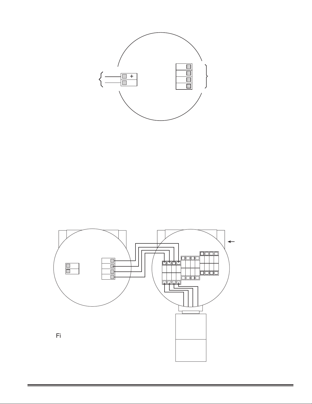
3.4.5 Remote Mounting Applications
Figure 3
BLK
BLU
YEL
WHT
MA
Sensor
4-20 mA Loop
+VDC
VDC Common
1234
WHT
BLK
YEL
BLU
Remote Transmitter
DM-400IS-RT
Remote Sensor
DM-400IS-RS
WHT
BLK
YEL
BLU
Plug unused port
with 3/4 NPT plug.
Some sensor mounting applications require that the gas sensor head be remotely mounted away from the sensor transmitter. This is usually true in instances where the gas sensor head must be mounted in a location that is difficult to
access. Such a location creates problems for maintenance and calibration activities. Detcon provides the Model Series
400IS in a remote-mount configuration in which the sensor and the transmitter are provided in their own condulet
housing and are interfaced together with a four conductor cable. Reference figure 4 for wiring diagram.
Figure #4
DM-400IS Toxic Gas Sensors PG.16
Page 17

3.5 START UP
Upon completion of all mechanical mounting and termination of all field wiring, apply system power and observe the
following normal condition:
a) Detcon electronic controller “Fault” LED is off.
b) A temporary upscale reading will occur as the sensor powers up. This upscale reading should clear to “0” ppm with-
in approximately 30 minutes of turn-on, assuming there is no gas in the area of the sensor.
NOTE: Zero Clearing with Biased Cells
Some electrochemical sensors are biased with an excitation voltage. When power to the sensor is lost, this bias voltage
slowly decays. When power is restored after long periods (multiple hours) of being unpowered, a surge in sensor output
takes place and a long and slow re-establishing of the sensor’s zero baseline takes place. This re-stabilization time may
range from 1 hour to 24 hours depending on the type of sensor and range of operation. The sensor types that this applies
to are the following: HCl, NO, NH3 (DM402IS-NH3), plus all the VOC sensors, C2H30, C2H2, C3H3N, C4H6, CS2,
COS, C2H6S, C3H5OCL, C2H5OH, C2H4, C2H4O, CH2O, CH3OH, C4H4S, C4H6O2, C6H5CH3 and C2H3CL.
If this characteristic is problematic for your specific application, a battery backup or uninterruptible power supply is recommended.
3.5.1 Initial Operational Tests
After a warm up-period has been allowed for, the sensor should be checked to verify sensitivity to its target gas.
Material Requirements
* Digital volt meter
* Jewelers type screwdriver
* Detcon PN 943-000217-5A1 Calibration Adapter
Span gas containing the target gas in air or nitrogen. It is recommended that the target gas concentration be 50% of
*
scale at a controlled flow rate of 500 ml/min. For example, a Model DM-400IS-H2S sensor in the range 0-100ppm
would require a test gas of 50ppm H2S. For a sensor with a range of 0-10ppm a test gas of 5ppm is recommended, etc.
a) Remove the junction box cover.
b) Measure the voltage between signal test points: zero gas conditions should provide a reading of between 39 and 40
mV DC. If necessary, adjust the zero potentiometer to achieve this reading.
c) Attach the calibration adapter to the sensor housing. Apply the test gas at a controlled flow rate of 500 ml/m. Observe
that the signal voltage increases to a level of 80 mV DC or higher.
d) Remove the test gas and observe that the signal decreases to between 39 and 40 mV DC.
Initial operational tests are complete. Detcon Model series DM-400IS sensors are pre-calibrated prior to shipment and
will, in most cases, not require significant adjustment on start up. However, Detcon recommends that a complete calibration test and adjustment be performed within 24 hours of installation. Refer to calibration instructions in later text.
3.6 CALIBRATION
Note: Calibration gas mixtures of the target gas in air or nitrogen are acceptable.
3.6.1 Material Requirements
* Digital volt meter
* Jewelers type screwdriver
* Detcon PN 943-000217-5A1 Calibration Adapter
* Span Gas containing the target gas in air or nitrogen.
NOTE 1: It is recommended that the target gas concentration be 50% of scale to assure optimum linearity. For
example, Model DM-400IS-H2S sensor in the range 0-100ppm would require a test gas of 50ppm H2S. For a sensor
with a range of 0-10ppm, a test gas of 5ppm would be recommended, etc. If a test gas will be used that has a concentration other than 50% of scale, see the additional instructions for determining the proper signal voltage in section 3.6.3 (Calibration Notes) below. To determine the gas and range of the sensor, refer to the sensor face plate
and/or external labeling.
DM-400IS Toxic Gas Sensors PG.17
Page 18

NOTE 2: The test gas should be delivered at a controlled flow rate of 500 ml/min. Flow rates below 500 ml/m may
T
E
X
A
S
H
O
U
S
T
O
N
SIGNAL
Model DM-4xx
ZERO
FINE
COARSE
Gas Sensor
detcon inc.
UNIVERSAL
TRANSMITTER
0
1
2
3
4
5
6
7
8
9
A
B
C
D
E
Span Adjustments
Plug-in Transmitter Circuit
Signal Test Points
cause inaccurate readings and are not recommended.
3.6.2 Span Calibration
1) Declassify the area around the sensor.
2) Remove the junction box cover.
3) Measure the voltage between signal test points. If necessary (outside the range of 38 to 42 mV DC), adjust the
“zero” potentiometer to achieve a reading of 40 mV DC.
NOTE:
Be sure there is no target gas present in the back-
ground or apply a zero gas standard to perform a zero calibration.
4) Attach the calibration adapter to the sensor housing.
5) Apply the test gas at a controlled flow rate of 500 ml/m. Wait 2-3 minutes for signal stability.
6) Set the “coarse” span rotary switch to the position that causes the signal to read closest to 120 mV DC.
7) Use the “fine” span potentiometer to adjust the signal to a reading of 120 mV DC. Note: if a signal of 120 mV DC cannot
be reached by turning the “fine” span potentiometer, turn the “coarse” span rotary switch up or down one position as necessary, then make final adjustments with the “fine” span potentiometer.
8) Remove the gas standard and calibration adapter. Observe that the signal decreases to ≈40 mV DC within 3-5 min-
utes. Make any needed adjustments to the “zero” potentiometer.
NOTE: Because there is interaction between the span and zero functions, it may be necessary to repeat steps 4 through 8.
Calibration is complete. Replace the splash guard and junction box cover.
3.6.3 Calibration Notes
Detcon Model DM-400IS series sensors provide a signal output of 4-20 mA DC which corresponds to 0-100% of scale. This
signal is reflected by a 40-200 mV DC voltage across the signal test points. Thus, if a sensor’s full scale range is 0-100ppm,
then the signal output will move by .16 mA (or 1.6 mV across the signal test points) for each 1ppm of movement.
To determine the signal movement per ppm, for other ranges, divide the full scale signal of 160 mV by the number of ppm in
the range of detection. For example, if a sensor’s range of detection is 0-25ppm, you would divide 160 mV by 25 to arrive at
the figure of 6.4 mV per ppm. This signal will begin its movement from a base line of 40 mV. Below is a listing of sample
detection ranges and the signals (as read from the signal test points) they will provide at different gas concentrations.
DM-400IS Toxic Gas Sensors PG.18
Page 19

RANGE RANGE RANGE RANGE
PPM
0 40 mV 40 mV 40 mV 40 mV
1 56 mV 46.4 mV 43.2 mV 41.6 mV
5 120 mV 72 mV 56 mV 48 mV
10 200 mV 104 mV 72 mV 56 mV
25 – 200 mV 120 mV 80 mV
50 ––200 mV 120 mV
100 –––200 mV
If calibration is being done with a gas concentration other than 50% of scale, you can determine the proper signal voltage by dividing 160 mV by the range of detection and then multiplying that figure by the concentration of gas. For
example, if you are calibrating a sensor with a range of 0-100ppm with a gas standard that contains 10ppm, you would
divide 160 (mV) by 100 (ppm) and then multiply that figure by 10 (ppm). Then add the base line of 40 (mV) to arrive
at the proper signal voltage of 56 mV.
3.6.4 Calibration Frequency
In most applications, monthly to quarterly calibration intervals will assure reliable detection. However, industrial environments differ. Upon initial installation and commissioning, close frequency tests should be performed, weekly to
monthly. Records should be kept. Less frequent test schedules should be implemented based on analysis of tests prior
to adjustment.
0-10ppm 0-25ppm 0-50ppm 0-100ppm
3.7 TROUBLE SHOOTING
Sensor reads Over-range after Power-up
Probable Cause: Biased sensor requiring additional stabilization time.
1. Verify if this is a Biased sensor (see section 3.5).
2. Wait up to 8 hours for unit to come on-scale if using a low range biased sensor.
3. Verify that there is not large amounts of target gas or interfering gases in background.
Reading Higher than Anticipated
Probable Causes: Target or Interfering gases in background, Incorrect calibration for Zero or Span, Biased sensor still
stabilizing.
1. Verify no target or interfering gases are present.
2. Redo Zero and Span calibrations with validated Zero Gas and Span Gas standards.
3. If recovering after a start-up, give more time to stabilize.
Reading Lower than Anticipated
Probable Causes: Target gas or Interfering gases in background during Zero Calibration, Zero Calibration done before
unit finished stabilizing, Incorrect Span Calibration.
1. Redo Zero and Span calibrations with validated Zero Gas and Span Gas standards.
Cannot Zero Calibrate to 40 mV
Probable Causes: Target gas or Interfering gases in background during Zero Calibration, Failed electrochemical sensor.
1. Verify no target or interfering gases are present.
2. Redo Zero and Span calibrations with validated Zero Gas and Span Gas standards.
3. If recovering after a start-up, give more time to stabilize.
Cannot do Span Calibration (not enough adjustment in span pots)
Probable Causes: Failed electrochemical sensor, ice/mud/dust blocking sensor membrane, invalid span calibration gas
do to age and contamination or insufficient flow rate.
1. Verify there is no ice/mud/dust blocking sensor membrane.
2. Redo Span Calibration with validated Span Gas standard (check with Pull Tube).
3. Replace with new electrochemical sensor.
DM-400IS Toxic Gas Sensors PG.19
Page 20

Sensor is Slow (>> 5 minutes) to stabilize on calibration gas
Probable Causes: Failed electrochemical sensor, ice/mud/dust blocking sensor membrane.
1. Verify there is no ice/mud/dust blocking sensor membrane.
2. Redo Span Calibration with validated Span Gas standard (check with Pull Tube).
3. Replace with new electrochemical sensor.
Sensor reads XXX mV on output
Probable Causes: Blown fuse(s) on Barrier PCB.
1. Replace sensor head (keep electrochemical sensor).
2. Consult Detcon for assistance.
Noisy Sensor (+/- 5-10 mV of continuous drift) or suddenly Spiking
Probable Cause: Unstable power source, Inadequate grounding, Inadequate RFI protection.
1. Verify power Source output and stability.
2. Contact Detcon for assistance in optimizing shielding and grounding.
3. Add RFI Protection accessory available from Detcon.
3.8 SPARE PARTS LIST
943-000006-132 Calibration Adapter for DM Sensors
897-850800-000 3 port enclosure less cover
897-850400-000 Enclosure cover
960-202200-000 Condensation prevention packet (replace annually).
500-512500-000 DM-400IS Base Connector Board
924-995480-000 Universal Plug-in Transmitter for Biased Sensors
924-995480-U01 Universal Plug-in Transmitter for Unbiased Sensors
Model Number Gas Name IS Sensor Head* Plug-in Replacement Sensor Cell
DM-400IS-C2H3O Acetyldehyde 394-12EA00-Range 370-12EA00-000
DM-400IS-C2H2 Acetylene 394-12EG00-Range 370-12EG00-000
DM-400IS-C3H3N Acrylonitrile 394-12EM00-Range 370-12EM00-000
DM-400IS-NH3 (-20°C) Ammonia 394-171700-Range 370-171700-000
DM-400IS-NH3 (-20°C) Ammonia 394-181800-Range 370-181800-000
DM-401IS-NH3 (-40°C) Ammonia 394-151500-Range 370-151500-000
DM-402IS-NH3 (CE) Ammonia 394-505000-Range 370-505000-000
DM-400IS-AsH3 Arsine 394-191900-Range 370-191900-000
DM-400IS-Br2 Bromine 394-747500-Range 370-747500-000
DM-400IS-C4H6 Butadiene 394-12EB00-Range 370-12EB00-000
DM-400IS-CS2 Carbon Disulfide 394-12EH00-Range 370-12EH00-000
DM-400IS-CO Carbon Monoxide 394-444400-Range 370-444400-000
DM-400IS-COS Carbonyl Sulfide 394-12EN00-Range 370-12EN00-000
DM-400IS-CL2 Chlorine 394-747400-Range 370-747400-000
DM-400IS-CLO2 (>10ppm) Chlorine Dioxide 394-747600-Range 370-747600-000
DM-401IS-CLO2 (≤10ppm) Chlorine Dioxide 394-777700-Range 370-777700-000
DM-400IS-B2H6 Diborane 394-192100-Range 370-192100-000
DM-400IS-C2H6S Dimethyl Sulfide 394-12EC00-Range 370-12EC00-000
DM-400IS-C3H5OCL Epichlorohydrin 394-12EI00-Range 370-12EI00-000
DM-400IS-C2H5OH Ethanol 394-12EO00-Range 370-12EO00-000
DM-400IS-CH3SH Ethyl Mercaptan 394-24EZ00-Range 370-24EZ00-000
DM-400IS-C2H4 Ethylene 394-12ED00-Range 370-12ED00-000
DM-400IS-C2H4O Ethylene Oxide Hi Range 394-12EJ00-Range 370-12EJ44-000
DM-400IS-C2H4O Ethylene Oxide 394-12EJ00-Range 370-12EJ00-000
DM-400IS-F2 Fluorine 394-272700-Range 370-272700-000
DM-400IS-CH2O Formaldehyde 394-12EP00-Range 370-12EP00-000
DM-400IS-GeH4 Germane 394-232500-Range 370-232500-000
DM-400IS-N2H4 Hydrazine 394-262600-Range 370-262600-000
DM-400IS-H2 (ppm) Hydrogen 394-848400-Range 370-848400-000
DM-401IS-H2 (LEL) Hydrogen 394-050500-Range 370-050500-000
DM-400IS-HBr Hydrogen Bromide 394-090800-Range 370-090800-000
DM-400IS-HCL Hydrogen Chloride 394-090900-Range 370-090900-000
DM-400IS-HCN Hydrogen Cyanide 394-131300-Range 370-131300-000
DM-400IS Toxic Gas Sensors PG.20
Page 21

DM-400IS-HF Hydrogen Flouride 394-333300-Range 370-333300-000
IS Sensor Head
Plug-in Transmitter
Base Connector Board
Enclosure
Enclosure Cover
#6 x .125" Nylon Washer (X2)
6-32 X 3/8 Screw (X2)
#6 Star Washer (X2)
#6 Flat Washer (X2)
Plug-in Sensor Cell
Condensation
Prevention Packet
(replace annually)
DM-400IS-H2S Hydrogen Sulfide 394-242400-Range 370-242400-000
DM-400IS-CH3OH Methanol 394-12EE00-Range 370-12EE00-000
DM-400IS-CH3SH Methyl Mercaptan 394-24EK00-Range 370-24EK00-000
DM-400IS-NO Nitric Oxide 394-949400-Range 370-949400-000
DM-400IS-NO2 Nitrogen Dioxide 394-646400-Range 370-646400-000
DM-400IS-O3 Ozone 394-393900-Range 370-393900-000
DM-400IS-COCL2 Phosgene 394-414100-Range 370-414100-000
DM-400IS-PH3 Phosphine 394-192000-Range 370-192000-000
DM-400IS-SiH4 Silane 394-232300-Range 370-232300-000
DM-400IS-SO2 Sulfur Dioxide 394-555500-Range 370-555500-000
DM-400IS-C4H8S Tetrahydrothiophene 394-434300-Range 370-434300-000
DM-400IS-C4H4S Thiophane 394-12EQ00-Range 370-12EQ00-000
DM-400IS-C6H5CH3 Toluene 394-12ER00-Range 370-12ER00-000
DM-400IS-C4H6O2 Vinyl Acetate 394-12EF00-Range 370-12EF00-000
DM-400IS-C2H3CL Vinyl Chloride 394-12EL00-Range 370-12EL00-000
* Does not include plug-in replacement sensor cell.
Specify 3 Digit Range as per examples below: If greater than 999ppm, use a “K” (for 1000). If greater than 9,900ppm
use a “P” (for %).
001 = 1ppm
005 = 5ppm
010 = 10ppm
020 = 20ppm
025 = 25ppm
050 = 50ppm
100 = 100ppm
500 = 500 ppm
01K = 1,000ppm
05K = 5,000ppm
01P = 1%
04P = 4%
25P = 25%
DM-400IS Toxic Gas Sensors PG.21
Page 22

3.9 WARRANTY
Detcon, Inc., as manufacturer, warrants each new electrochemical toxic gas plug-in sensor cell, for a specified period
under the conditions described as follows: The warranty period begins on the date of shipment to the original purchaser and ends after the specified period as listed in the table in Section 3.3. The sensor cell is warranted to be free from
defects in material and workmanship. Should any sensor cell fail to perform in accordance with published specifications
within the warranty period, return the defective part to Detcon, Inc., 3200 A-1 Research Forest Dr., The Woodlands,
Texas 77381, for necessary repairs or replacement.
3.10 SERVICE POLICY
Detcon, Inc., as manufacturer, warrants under intended normal use each new DM-400IS series plug-in signal Transmitter
and intrinsically safe Sensor Head circuit to be free from defects in material and workmanship for a period of two years
from the date of shipment to the original purchaser. Detcon, Inc., further provides for a five year fixed fee service policy wherein any failed signal Transmitter shall be repaired or replaced as is deemed necessary by Detcon, Inc., for a fixed
fee of $35.00. Any failed intrinsically safe Sensor Head circuit shall be repaired or replaced as is deemed necessary by
Detcon, Inc., for a fixed fee of $55.00. The fixed fee service policy shall affect any factory repair for the period following the two year warranty and shall end five years after expiration of the warranty. All warranties and service policies are
FOB the Detcon facility located in The Woodlands, Texas.
3.11 REVISION LOG
Date
12/07/2004
Version
1.5.6
Changes
Previously issued
08/19/2010 1.5.7 Changed calibration adapter to threaded version(943-000006-
132) from twist-lock.
11/08/2010 1.5.8 Corrected wrong data for CO interference with C2H3CL,previ-
ous value 1250=100, new date 200=100
Approval
BM
BM
BM
Shipping Address: 3200 A-1 Research Forest Dr., The Woodlands, Texas 7381
Mailing Address: P.O. Box 8067, The Woodlands, Texas 77387-8067
phone 888-367-4286, 281-367-4100 • fax 281-292-2860 • www.detcon.com • sales@detcon.com
DM-400IS Toxic Gas Sensors PG.22
 Loading...