

Page 1
m
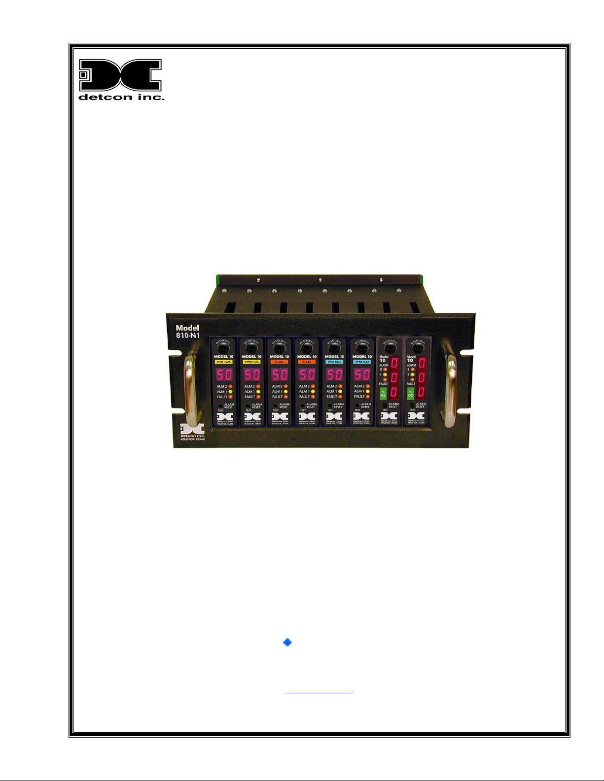
Model 810-N1-24VDC
Panel Mount Control Enclosure
Operator’s Installation and Instruction Manual
The Woodlands, Texas 77387
Ph.281.367.4100 / Fax 281.298.2868
July 30,2011 • Document #3083 • Revision 0.0
DETCON, Inc.
3200 Research Forest Dr.,
www.detcon.co
Page 2

810-N1-24VDC
This page left intentionally blank
810-N1-24VDC Instruction Manual ii
Page 3

810-N1-24VDC
Table of Contents
1.0 INTRODUCTION ................................................................................................................................... 1
2.0 DESCRIPTION........................................................................................................................................ 1
3.0 SPECIFICATIONS ................................................................................................................................. 1
4.0 REMOTE RESET ................................................................................................................................... 2
5.0 INSTALLATION..................................................................................................................................... 2
6.0 START-UP ............................................................................................................................................... 3
7.0 MAINTENANCE AND REPAIR........................................................................................................... 3
8.0 SPARE PARTS........................................................................................................................................4
9.0 WARRANTY ........................................................................................................................................... 4
Appendix C.........................................................................................................................................................5
Revision History............................................................................................................................................... 5
Table of Figures
Figure 1 810-N1-24VDC dimensions ...............................................................................................................2
Figure 2 Wiring Terminations...........................................................................................................................2
810-N1-24VDC Instruction Manual iii
Page 4

810-N1-24VDC
Shipping Address: 3200 A-1 Research Forest Dr., The Woodlands Texas 77381
Mailing Address: P.O. Box 8067, The Woodlands Texas 77387-8067
Phone: 888.367.4286, 281.367.4100 • Fax: 281.292.286 0 •
810-N1-24VDC Instruction Manual iv
www.detcon.com • [email protected]
Page 5

810-N1-24VDC
1.0 INTRODUCTION
Detcon Model 810-N1-24VDC Rack consists of 3 major assemblies:
1 The NEMA 1 rackmount control enclosure.
2 The single channel digital control modules.
3 The remote mount gas sensor assemblies.
The NEMA 1 control enclosure is detailed in section 1.0 of the manual, the control modules in section 2.0, and
applicable sensor assemblies in section 3.0.
2.0 DESCRIPTION
Detcon Model 810-N1-24VDC along with Model 10B digital control modules is designed to serve as a host
assembly for up to eight remote mount gas detection sensor assemblies. The control enclosure is rated NEMA
1 suitable for installation in non-hazardous locations. The single channel modular design supports application
flexibility wherein multiple function gas detection systems can be configured in any combination up to eight
channels. All control modules are plug-in front panel accessible for easy maintenance and repair.
Discreet output terminal strips located on the controller motherboard are provided for sensor terminations,
Form C dry contact alarm outputs (normally open, normally closed and common) for two alarms plus fault, 420 mA outputs for remote recording devices, and RS-485 serial Modbus™. Additional terminations are
provided for VDC power in, and remote alarm reset.
Form C relay outputs may be discreet or zoned by gold plated jumper tabs located on the controller mother
board.
3.0 SPECIFICATIONS
Electrical Classification NEMA 1
Dimensions 7"W, 5.25"H, 8"D
Capacity 8 Single Channels
Power Input 24 VDC
Alarm Contacts Discreet Fault, Low, High, per Channel
5 Amps @ 30VDC / 5 Amps @ 125VAC
Common, Normally Open and Normally Closed
Outputs Discreet 4-20 mA DC
Serial RS-485 Modbus™
Operating Temperature Range -40°F to +175°F
Power Consumption <5 Watts per Channel (includes gas sensor and control module)
Warranty Two Years
810-N1-24VDC Instruction Manual Rev. 0.0 Page 1 of 6
Page 6
810-N1-24VDC
4.0 REMOTE RESET
The reset function is effective when the Model 10B's respective alarms have been programmed in the latching
position and alarm conditions have passed. The alarm reset function is common to all controllers and is
activated by closing the circuit between the two reset contacts. A normally open momentary switch is suitable.
5.0 INSTALLATION
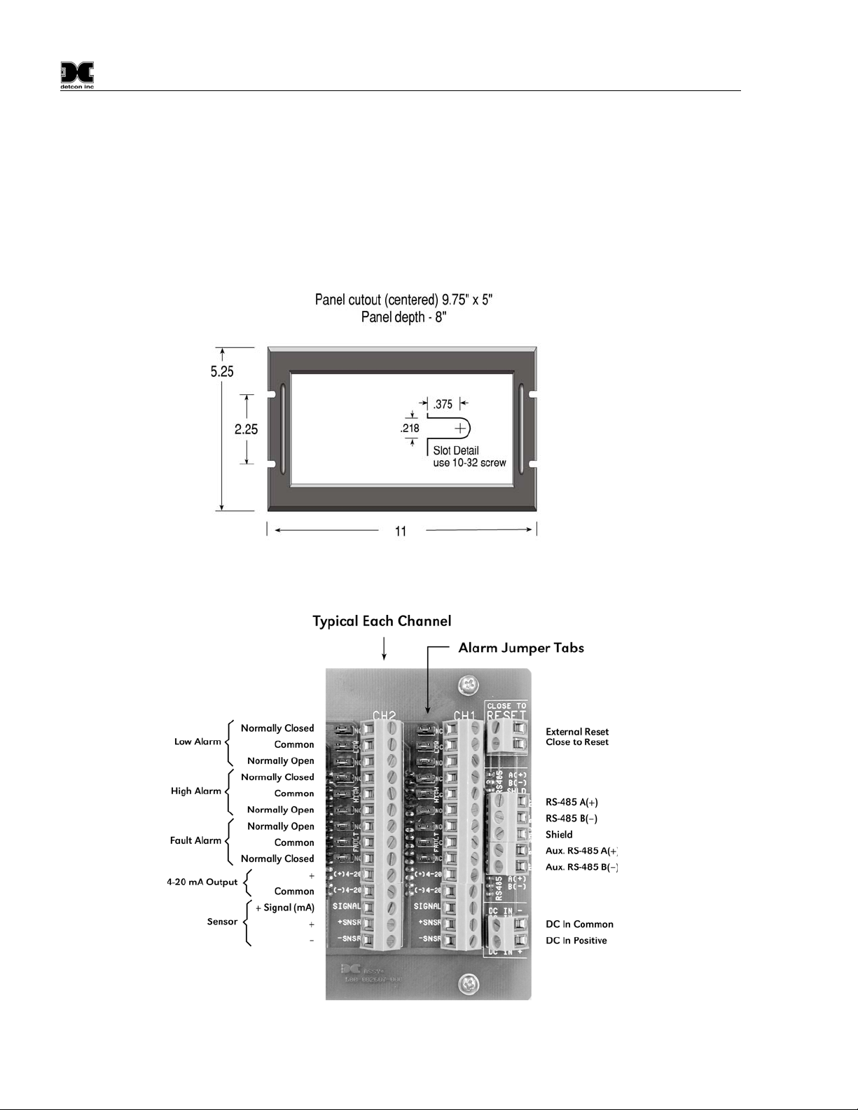
1. Securely mount the 810-N1-24VDC rack enclosure in accordance with Figure 1.
Figure 1 810-N1-24VDC dimensions
Note:
Reference figure 2 for wiring terminations
Figure 2 Wiring Terminations
810-N1-24VDC Instruction Manual Rev 0.0 Page 2 of 6
Page 7

810-N1-24VDC
Caution: Observe correct polarity when terminating all input/output field wiring. Failure to do so may
result in circuit damage on power up.
2. Observe correct polarity when terminating all input/output field wiring. Failure to do so may
result in circuit damage on power up.
3. Connect 24 VDC input to the terminal strip labeled “DC IN” (+ and –).
4. If applicable, connect a normally open momentary remote mounted switch to the lugless terminal
(labeled RESET) located on the controller mother board.
5. If applicable, terminate the discrete 4-20 mA output to external device(s): Terminals are labeled
“(+) 20” and “(–) 4-20”.
6. If applicable, terminate the RS-485 serial output to external device(s). Terminals are labeled “A
(+)”, (–)”, and “SHLD”.
7. Refer to installation and wiring detail of remote mount sensor assemblies as detailed in section
3.0. Terminate field wiring from sensors to Model 410-N1-24VDC rack lugless terminal strips
located on controller mother board.
8. Alarm relay outputs may be discrete, zoned, or common via gold plated jumper tabs. Configure
accordingly.
Note: Based on the application and use of relay contact outputs, complete all wiring terminations prior
application of power. Shut-in controls may be omitted until system test is complete.
6.0 START-UP
Upon completion of all field wiring: Apply 24 VDC power. Note that each Model 10B controller digital
display illuminates. Varying readings may occur during sensor warm-up. A 10 second alarm delay will on
power up. Refer to sections 2.0 and 3.0 for additional start-up detail.
7.0 MAINTENANCE AND REPAIR
The Detcon Model 410-N1s modular design allows for minimum down time during maintenance and/repair. A
model 10B control module may be changed by turning the latch knob clockwise until it stops and then sliding
it out of the panel by pulling on the latch knob. To install, slide the 10B control module into the 410-N124VDC control enclosure and then secure by turning the latch knob counter-clockwise until it stops. See
section 3 for more information on the 10B control module.
810-N1-24VDC Instruction Manual Rev 0.0 Page 3 of 6
Page 8

810-N1-24VDC
8.0 SPARE PARTS
0224 Gold plated jumper tab
910-000008-003 Model Series 10 Blank Plate
9.0 WARRANTY
Detcon inc., as manufacturer, warrants under intended normal use each new Model 810-N1-24VDC rack
control enclosure to be free from defects in material and workmanship for a period of one year. The warranty
period begins from the date of shipment to the original purchaser and ends one year thereafter. All warranties
and service policies are FOB the Detcon Inc. facility located in The Woodlands, Texas.
810-N1-24VDC Instruction Manual Rev 0.0 Page 4 of 6
Page 9

810-N1-24VDC
Appendix C
Revision History
Revision Date Changes made Approval
0.0 07/22/2011 Original Release. RH
810-N1-24VDC Instruction Manual Rev 0.0 Page 5 of 6
Page 10

810-N1-24VDC
This page left intentionally blank
Shipping Address: 3200 A-1 Research Forest Dr., The Woodlands Texas 77381
Mailing Address: P.O. Box 8067, The Woodlands Texas 77387-8067
Phone: 888.367.4286, 281.367.4100 • Fax: 281.292.286 0 •
810-N1-24VDC Instruction Manual Rev 0.0 Page 6 of 6
www.detcon.com • [email protected]
 Loading...