

Page 1

DETCON, Inc.
May 29. 2014 • Document # 4429 • Revision 1.3
Model CX-DM
CX-DM Toxic Gas Sensors
CX-DM O2 Deficiency Sensors
Operator’s Installation and Instruction Manual
Covers all Model CX-DM Sensors
4055 Technology Forest Blvd, Suite 100
The Woodlands, Texas 77381
Phone: 713.559.9200 • Fax: 281.292.2860
www.detcon.com
Page 2

Model CX-DM
This page left intentionally blank
Model CX-DM ii
Page 3

Model CX-DM
Table of Contents
1. Introduction ..................................................................................................................................................1
1.1 Description .......................................................................................................................................... 1
1.2 Modular Design .................................................................................................................................. 2
2. Installation ....................................................................................................................................................3
2.1 Hazardous Locations Installation Guidelines for Safe Use ................................................................. 3
2.2 Sensor Placement ................................................................................................................................ 4
2.3 Sensor Contaminants and Interference ............................................................................................... 5
2.4 Sensor Mounting ................................................................................................................................. 5
2.5 Electrical Installation .......................................................................................................................... 6
2.6 Field Wiring ........................................................................................................................................ 7
2.6.1 Terminal Connections 3-Wire 4-20mA .......................................................................................... 7
2.6.2 Terminal Connections 4-20mA and RS-485 .................................................................................. 8
2.7 Initial Start Up..................................................................................................................................... 9
2.7.1 O
3. Operation ....................................................................................................................................................11
3.1 Operator Interface ............................................................................................................................. 12
3.2 Normal Operation ............................................................................................................................. 13
3.3 Calibration Mode .............................................................................................................................. 13
3.3.1 AutoZero ....................................................................................................................................... 14
3.3.2 AutoSpan ...................................................................................................................................... 15
3.4 Program Mode .................................................................................................................................. 17
3.4.1 View Sensor Status ....................................................................................................................... 17
3.4.2 Set Detection Range ..................................................................................................................... 18
3.4.3 Set AutoSpan Level ...................................................................................................................... 18
3.4.4 Bump Test .................................................................................................................................... 18
3.4.5 Restore Defaults ........................................................................................................................... 19
3.4.6 Set Modbus ID .............................................................................................................................. 19
3.5 Fault Diagnostic/Failsafe Feature ..................................................................................................... 20
4. Modbus™ Communications .......................................................................................................................21
4.1 General Modbus™ Description ........................................................................................................ 21
4.2 Modbus™ Register Map & Description ........................................................................................... 21
4.2.1 Sensor Faults – Register 40005 .................................................................................................... 22
4.2.2 Temperature Compensation – Register 40012 ............................................................................. 23
5. Service and Maintenanc e ............................................................................................................................24
5.1 Replacement of Plug-in Sensor ......................................................................................................... 24
5.2 Replacement of ITM – Aluminum J-Box ......................................................................................... 25
5.3 Replacement of ITM – Stainless Steel Mini Condulet
6. Troubleshooting Guide ...............................................................................................................................27
6.1 Under-Range problems ..................................................................................................................... 27
6.2 Stability problems ............................................................................................................................. 27
6.3 Clearing problem .............................................................................................................................. 27
6.4 Poor Calibration Repeatability .......................................................................................................... 28
6.5 Unstable Output/ sudden spiking ...................................................................................................... 28
6.6 Nuisance Alarms ............................................................................................................................... 28
6.7 Intelligent Transmitter Module (ITM) not responding ..................................................................... 28
7. Customer Support and Service Policy ........................................................................................................29
7.1 Warranty Notice ................................................................................................................................ 29
7.2 CX-DM Sensor Warranty ................................................................................................................. 30
8. Appendix ....................................................................................................................................................31
Deficiency Sensors .................................................................................................................. 10
2
...................................................................... 25
Model CX-DM iii
Page 4

Model CX-DM
Shipping Address: 4055 Technology Forest, Suite 100, The Woodlands, Texas 77381
Phone: 713.559.9200 • Fax: 281.292.2860 •www.detcon.com • sales@detcon.com
8.1 Specifications .................................................................................................................................... 31
8.2 Sensor Specific Data ......................................................................................................................... 32
8.3 Interfer ence Tabl e ............................................................................................................................. 34
8.4 Spare Parts, Sensor Accessories, Calibration Equipment ................................................................. 40
8.5 Revision Log ..................................................................................................................................... 40
Table of Figures
Figure 1 Construction of Electrochemical Toxic Sensor ...................................................................................... 1
Figure 2 Construction of Galvanic Cell ................................................................................................................ 1
Figure 3 Sensor Assembly Breakaway ................................................................................................................. 2
Figure 4 Functional Block Diagram ..................................................................................................................... 2
Figure 5 Plug-in Sensor ........................................................................................................................................ 3
Figure 6 Approval Label ...................................................................................................................................... 3
Figure 7 CX-DM Sensor with Mini-Condulet ...................................................................................................... 6
Figure 8 Sensor Wire Connections ....................................................................................................................... 8
Figure 9 Terminal Interconnect ............................................................................................................................ 9
Figure 10 Magnetic Programming Tool ............................................................................................................. 11
Figure 11 Magnetic Programming Switches ...................................................................................................... 12
Figure 12 Software flow chart ............................................................................................................................ 13
Figure 13 Modbus™ Frame Format ................................................................................................................... 21
Figure 14 Sensor Cell and ITM Mating ............................................................................................................. 24
List of Tables
Table 1 Protection vs. Wire Gauge....................................................................................................................... 7
Table 2 CX-DM Register Map ........................................................................................................................... 22
Table 3 Sensor Specific Data ............................................................................................................................. 32
Table 4 Interfering Gases ................................................................................................................................... 34
Table 5 Cross Interference Table ....................................................................................................................... 35
Mailing Address: P.O. Box 8067, The Woodlands Texas 77387-8067
Model CX-DM iv
Page 5

Model CX-DM
1. Introduction
1.1 Description
Detconꞌs CX-DM sensor for toxic gas and O
monitor a wide range of toxic gases in air. Detection ranges for toxic gases are 0-1ppm up to 0-10,000ppm
(typical ranges of detection are 0-10ppm, 0-25ppm, 0-50ppm and 0-100ppm). Ranges for O
1% up to 0-25% by volume. The basic sensor assembly consists of an electrochemical sensor mounted in an
intrinsically safe stainless steel housing and includes a Splash Guard Cal Adapter.
Electrochemical Sensor Technology
The toxic gas sensors are based on electrochemical cells. Each cell consists of three electrodes embedded in an
electrolyte solution and housed beneath a diffusion membrane. Sensitivity to target gases is achieved by
varying composition of any combination of the sensor components. The cells are diffusion limited by way of
small capillary barriers resulting in a long service life of three or more years. The electrochemical cell is
packaged as a field replaceable plug -in sensor.
deficiency are non-intrusive sensors designed to detect and
2
deficiency are 0-
2
Figure 1 Construction of Electrochemical Toxic Sensor
Principle of Ope r at io n
The O
deficiency sensor technology is a two electrode galvanic metal air battery type cell housed as a field
2
replaceable intelligent plug-in sensor. The cell is diffusion limited and functions as a direct current generator
proportional to the amount of oxygen adsorption. The sensors are temperature compensated and show good
accuracy and stability over the operating temperature range of -20°C to 50°C (-4°F to +122°F). The sensor is
warranted for two years with an expected service life of up to 2.5 years in ambient air at 20.9% oxygen.
Figure 2 Construction of Galvanic Cell
CX-DM Instruction Manual Rev. 1.3 Page 1 of 40
Page 6

Model CX-DM
CX-DM Bottom
Housing Assembly
Plug-in Replaceable
Sensor
Intelligent Transmitter Module (ITM)
Micro-processor controlled circuit
encapsulated in an Explosion proof
housing.
Magnetic
Programming Switches
Splash Guard
3
4
" NPT Locking
Nut
All metal components are constructed from electro polished 316 Stainless Steel to
maximize corrosion resistance in harsh environments.
mA Output
Power In
Power
Intrinsically
Safe Barrier
Modbus Output
1.2 Modular Design
The CX-DM sensor assembly is completely modular and is composed of four parts (Figure 3).
1. CX-DM Intelligent Transmitter Modu le (I TM)
2. Plug-in Electrochemical Sensor (varies by gas type and range)
3. CX Series Bottom Housing
4. Splash Guard
Figure 3 Sensor Assembly Breakaway
NOTE
CX-DM Intelligent Transmitter Module
The transmitter module is microprocessor-based and attached to the explosion proof junction box. Circuit
functions include an intr insi cal ly s af e b arri er , on-board power supply, microprocessor, magnetic programming
switches, and a linear 4-20mA DC output. Magnetic program switches (located on either side of the ITM) are
activated by a hand-held magnetic programming tool, allowing non-intrusive operator interface with the
transmitter module. Electrical classifications are Class I, Div 1, Groups B, C, and D.
Plug-In
Sensor
Micro-
Processor
I/O
Circuit
Protection
supplies
Figure 4 Functional Bloc k Diagram
Field Replaceable Sensor
Detconꞌs electrochemical gas sensors are field proven, plug-in sensors with over-sized gold-plated connections
that eliminate corrosion problems. The sensor can be easily accessed and replaced in the field by releasi ng the
locking screw and unthreading the splashguard adapter assembly. Detconꞌs toxic sensors have a long shelf life
and supported by an industry-leading warranty.
CX-DM Instruction Manual Rev. 1.3 Page 2 of 40
Page 7
Model CX-DM
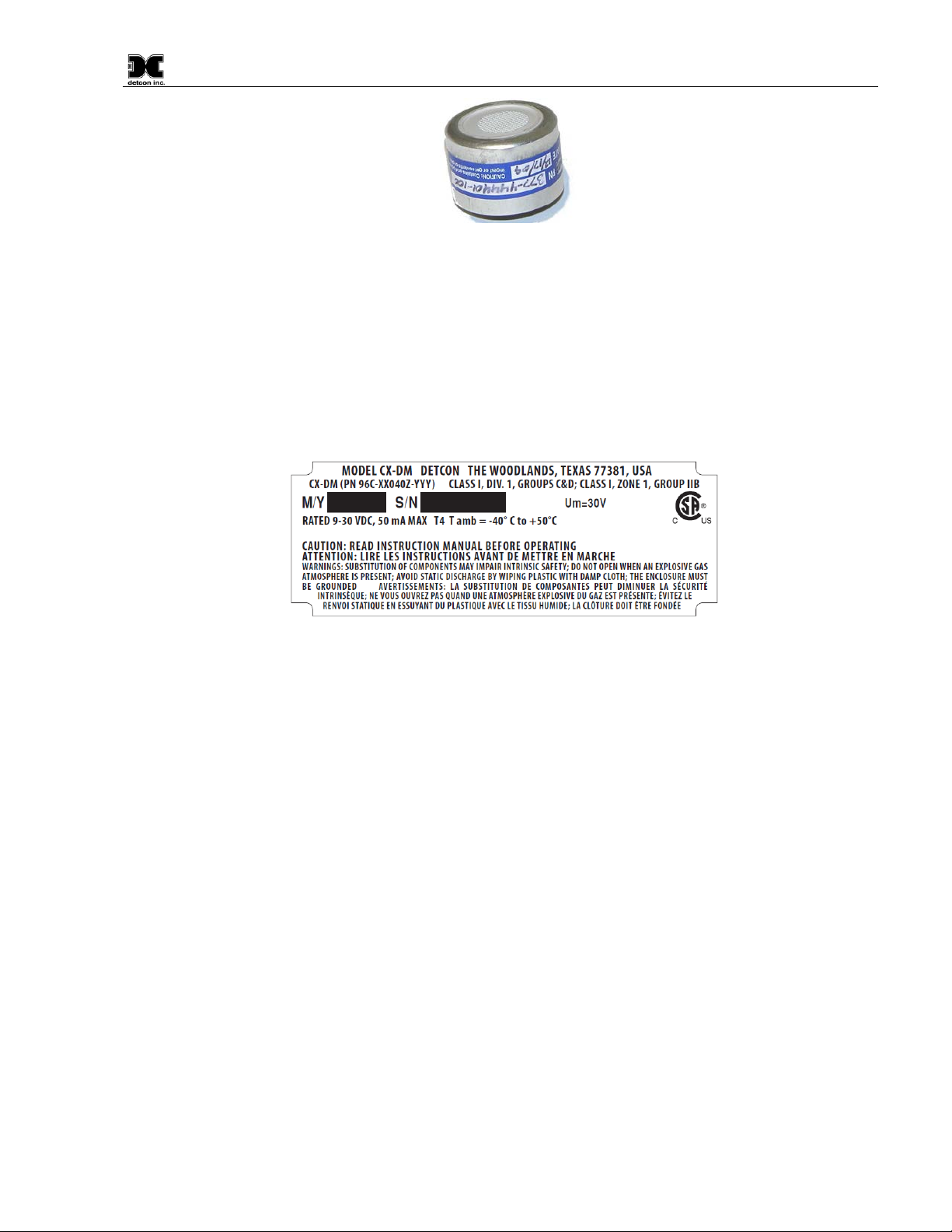
Figure 5 Plug-in Sens or
2. Installation
2.1 Hazardous Location s Installation Guidelines for Safe Use
1. Install the sensor only in areas with classifications matching the approval label. Follow all warnings
listed on the label.
Figure 6 Approval Label
2. Do not remove the junction box cover while in the classified are unless it is conformed the there is no
explosive gas levels in the area.
3. A good ground connection should be verified between the sensor’s metal enclosure and the junction
box. If a good ground connection is not made, the sensor can be grounded to the junction box using
the sensor’s external ground lug. Verify a good ground connection between the junction box and earth
ground.
4. Proper precautions should be taken during installing and maintenance to avoid the build-up of static
charge on the plastic components of the sensor (Splash Guard) Wipe with damp cloth on plastic
components to avoid static discharge.
5. Do not substitute components. Substitution of components may impair the intrinsic safety rating.
6. Do not operate the sensor outside of the stated operating temperature limits.
7. Do not operate the sensor outside the stated operating limits for voltage supply.
8. These sensors meet ATEX standards EN60079-0:2012. EN60079-1:2007 and EN60079-11:2012.
9. These sensors have a maximum safe location voltage of Um=30V.
10. The CX-DM apparatus is not capable of withstanding the 500V insulation test required by clause
6.3.12 of IEC/EN 60079-11:2007 (and by clause 6.8.1 of CSA Std. 142); thus, the enclosure must be
grounded.
CX-DM Instruction Manual Rev. 1.3 Page 3 of 40
Page 8

Model CX-DM
In all installations, the gas sensor should point straight down. Improper sensor orientation
may result in false readings and permanent sensor damage.
11. The CXT-DM may be used as an oxygen deficiency sensor; the CXT-DM must not be used for
detecting oxygen concentrations expected to be greater than 21%
12. The CXT-DM must only use gas sensor cell model 371-xxxx00-yyy. No other gas sensor shall be
used.
2.2 Sensor Placement
Sensor location is critical to the overall safe performance of the product. Confirm that the following five
factors are verified during sensor placement.
1. Density of the gas to be detected
2. Most probable leak sources within the industrial process
3. Ventilation or prevailing wind conditions
4. Personnel exposure
5. Maintenance access
Density
Sensor placement should be relative to the density of the target gas. For the detection of heavier than air gases,
sensors should be located within 4 feet of grade since heavy gases typically settle in low lying areas. For gases
lighter than air, sensor placement should be 4 to 8 feet above grade in open areas or in pitched areas of
enclosed spaces.
Leak Sources
The most leak sources in an industrial process are flanges, valves, and tubing connections where seals may
either fail or wear. Other leak sources are best determined by facility engineers with experience in similar
processes.
Ventilation
Normal ventilation or prevailing wind conditions can dictate efficient location of gas sensors in a manner
where the movement of gas clouds is quickly detected.
Personnel Exposure
The undetected migration of gas clouds should not be allowed to approach concentrated personnel areas such
as control rooms, maintenance or warehouse buildings. Selecting sensor location should combine leak so urce
and perimeter protection in the best possible configuration.
Maintenance Access
Consideration should be given to providing easy access for maintenance personnel and the consequences of
close proximity to contaminants that may cause the sensor to wear prematurely.
NOTE
CX-DM Instruction Manual Rev. 1.3 Page 4 of 40
Page 9

Model CX-DM
If wall mounting without a mounting plate, make sure to use at least 1/2" spacers underneath
the wall and to allow access to the sensor assem bly .
Metal-on-metal contact must be maintained to provide a solid electrical ground path. Only
be externally
grounded using a ground strap.
Additional Placement Considerations
The sensor should not be positioned where it might be sprayed or coated with surface contaminating
substances. Painting sensor assemblies is prohibited.
Although the sensor is designed to be RFI resistant, it should not be mounted in close proximity to highpowered radio transmitters or sim ilar RFI generati ng equipment.
When possible mount in an area void of high wind, accumulating dust, rain, splashing from hose spray, direct
steam releases, and continuous vibration. If the sensor cannot be mounted away from potentially damaging
conditions then use the Detconꞌs Harsh Location Dust Guard accessory.
Do not mount in locations where temperatures will exceed the operating temperature limits of the sensor. Use
a sunshade to maintain correct operating temperature if mounted in direct sun light.
2.3 Sensor Cont aminants and Interferen ce
Electrochemical toxic gas may be adversely affected by exposure to other airborne gases. Depending on the
cross-sensitivity relationship, there may be a false high or false low reading. The most common gases that may
cause interference are referenced in Section 8.3 (Table 4 and Table 5).
Cross-Interference Data T ab le
Gases typically found in industrial environments that may cause interference with Detconꞌs toxic gas sensors
are listed in Section 8.3, Table 5. To effectively reference the table; locate the chosen gas, scan across the row
for possible interference gases, and then determine the magnitude of cross-interference that may occur.
2.4 Sensor Mounting
Vertically position the CX-DM so the sensor points straight down. The explosion-proof enclosure or junction
box is typically mounted on a wall or pole. Detcon provides a selection of standard junction boxes in
aluminum and stainless steel.
NOTE
NOTE
When mounting on a pole, secure the junction box to a suitable mounting plate and attach the mounting plate
to the pole using U-Bolts. (Pole-Mounting brackets for Detcon junction boxes are available separately .)
the aluminum junction boxes 1/4" mounting holes to move the sensor assembly away from
use Teflon Tape or other pipe thread material on the 3/4" threads if the sensor is mounted in
a severe or harsh environment. If Teflon Tape is used the Sensor must
CX-DM Instruction Manual Rev. 1.3 Page 5 of 40
Page 10
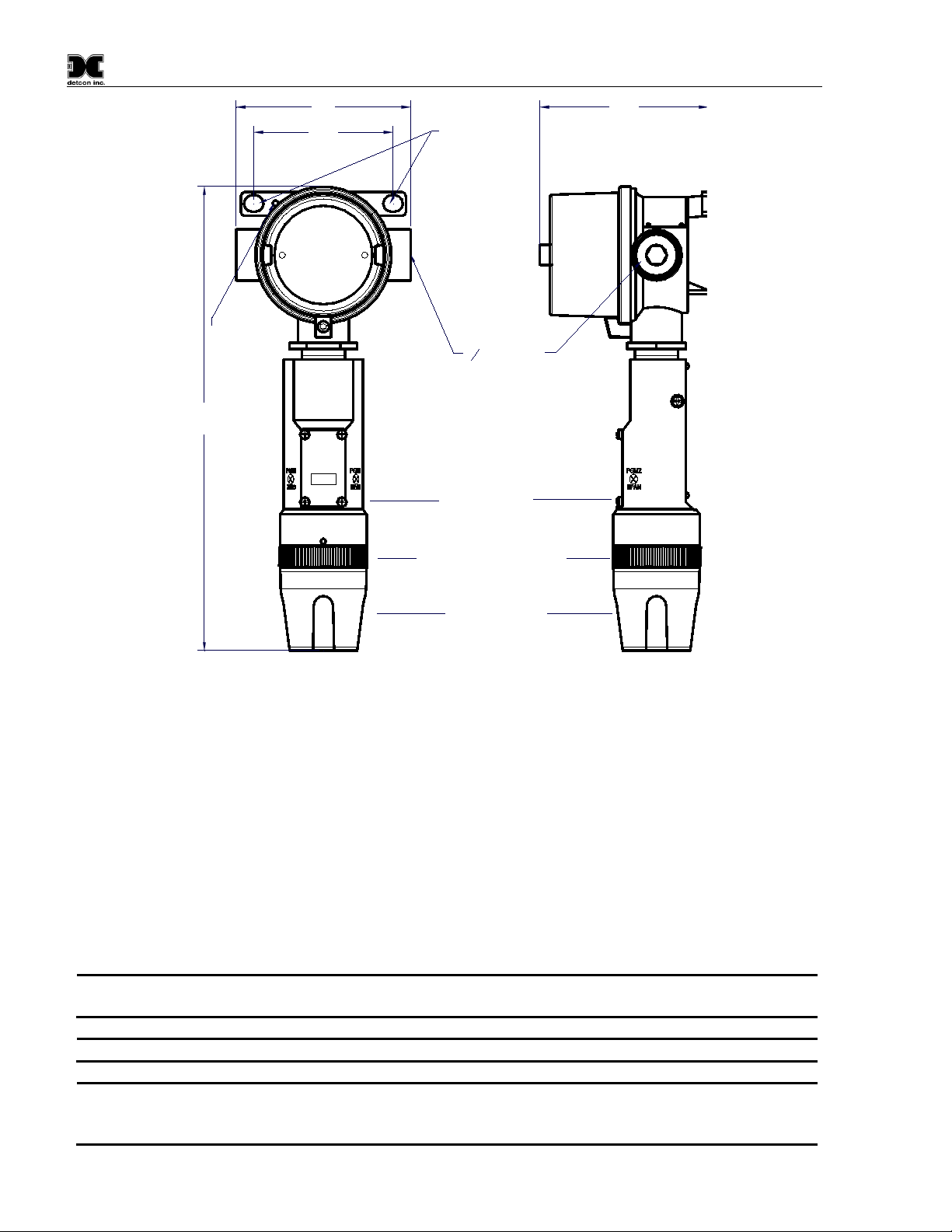
Model CX-DM
6-32 tapped
ground point
3.45
3
4
NPT Port
4.2
Ø0.4 X 0.475"
mounting
holes
Splash Guard Adapter
Splash Guard
ITM Assembly
Typ.
3.47
A conduit seal is required to be located within 18" of the J-Box and sensor assembly.
Crouse Hinds type EYS2, EYD2 or equivalent are suitable for this purpose.
NOTE
Water damage from water leaking into the enclosure is not covered by the Detcon warranty.
Unused ports should be blocked with suitable 3/4" male NPT plug. Detcon supplies one 3/4"
appropriate male plug of like construction material.
2.5 Electrica l Installation
Figure 7 CX-DM Sensor with Mini-Condulet
The sensor assembly wiring should be installed in accordance with local electrical codes. Proper electrical
installation of the gas sensor is critical for conformance to electrical codes and to avoid damage due to water
leakage.
If a conduit run exists, a drain should be incorporated. The drain allows condensation inside the conduit run to
drain safely away from the sensor assembly. Electrical seals act as a secondary seal to prevent water from
entering the wiring enclosure. However, electrical seals are not designed to provide an absolute watertight seal,
especially when used in the vertical orientation. The electrical seal fitting is required to meet the National
Electrical Code per NEC Article 500-3d (or Canadian Electrical Code Handbook Part 1 Section 18-154).
Requirements for locations of electrical seals are covered under NEC Article 501-5.
NOTE
NOTE
NPT male plug with each J-box enclosure. If connections are other than 3/4" NPT, use an
CX-DM Instruction Manual Rev. 1.3 Page 6 of 40
Page 11

Model CX-DM
CAUTION
Over-Current
Protection
22
0.723mm
3A
20
0.812mm
5A
18
1.024mm
7A
16
1.291mm
10A
14
1.628mm
20A
NOTE 1: Wiring table is based on stranded tinned copper wire and is designed to serve as a
reference only.
NOTE 2: Shielded cable is required for installations where cable trays or conduit runs include
high voltage lines or other possible sources of induced interference. Separate conduit runs are
highly recommended in these cases.
NOTE 3: The supply of power should be from an isolated source with over-current pr ot ect i on
as stipulated in ta b le.
Do not apply system power to the sensor until all wiring is properly terminated
(Section 2.7).
2.6 Field Wiring
Detcon Model CX-IR se nsor assemblies require three conductor connections between power supplies and host
electronic controller’s 4-20mA output. Wiring designations are + (DC), – (DC), and mA (sensor signal.
Maximum wire ohmic resistance between sensor and 24VDC source is defined below. Maximum wire size for
termination in the De tc o n J-Box accessory is 14 gauge.
Max Resistance drop on red and black wire is 10 ohms. This considers wire diameter, wire length and
maximum operation temperature.
Max loop load resistance between green and black wire is 500 ohms. Minimum loop load resistance between
green and black wire is 100 ohms. This is considers wire diameter, wire length, max operating temperature
and selected termination resistor.
AWG Wire Dia.
Table 1 Protection vs. Wire Gauge
2.6.1 Terminal Connections 3-Wire 4-20mA
CAUTION: Do not apply System power to the sensor until all wiring is properly terminated. Refer to
Section 2.5 Initial Start Up
CX-DM Instruction Manual Rev. 1.3 Page 7 of 40
Page 12

Model CX-DM
mA
(+)
(-)
Wiring to
Sensor Assembly
Red
Green
Black
Explosion
Proof
Junction Box
(+)
mA
(-)
Wiring to
Controller
Red
Green
Black
Detcon Inc.
Rev. 1
440-005208-000
MODULE
PROTECTION
TRANSIENT
Figure 8 Sensor Wire Connecti ons
a) Remove the junction box cover. Identify the terminal blocks for customer wire connections.
b) Observing correct polarity, terminate the 3-conductor 4-20mA field wiring (+, -, mA) to the sensor
assembly wiring in accordance with the detail shown in Figure 8.
c) Replace the junction box cover.
2.6.2 Terminal Connections 4-20mA and RS-485
1. Remove the junction box cover.
2. Connect the incoming 24V to the terminal labeled "+" and 24V return to the terminal labeled "–". Connect
the mA output to the “mA” terminal and the Modbus signals (if used) to the “A” and “B” terminals. Note:
the “Y” terminal is not used.
3. Replace the junction box cover after Initial Start Up (Section 2.7).
CX-DM Instruction Manual Rev. 1.3 Page 8 of 40
Page 13

Model CX-DM
B
A
mA
VV+
Black
Red
Green
Blue
White
White
Blue
Green
Red
Black
To Sensor
Wiring
Ferrite
Bead
A 6-32 or 8-32 threaded exterior ground point is provided on most junction boxes for an
strap must be used to ensure that the sensor is electrically grounded.
Figure 9 Terminal Interconnect
NOTE
external ground. If the sensor assembly is not mechanically grounded, an external ground
2.7 Initial Start Up
Toxic Gas Sensors
Upon completion of all mechanical mounting, apply power to the sensor. Observe the following normal
conditions:
1. Upon power up, the sensor will scroll "CX-DM V##.##" and will then display the current reading for
about 5 seconds. A temporary upscale reading may occur as the sensor stabilizes. This upscale reading
will decrease to "0" ppm within 1 to 2 minutes of power-up, assuming there is no gas in the area of the
sensor. Sensors cells that use a bias voltage require a longer time to stabilize. This can vary between 1
and 24 hours depending on the sensor type and range. Biased sensors include NH
VOC gases (ethylene oxide, ethylene, methanol, formaldehyde….etc.).
2. After the initial power up, the sensor display will turn off . T hereafter the display will come on once
every 10 seconds, display the current reading for 2 seconds, and then return to a blank display.
, NO, HCl, and
3
Initial Operational Tests
After a warm up period of 1 hour (or when zero has stabilized), verify that the sensor has sensitivity to the
target gas.
CX-DM Instruction Manual Rev. 1.3 Page 9 of 40
Page 14

Model CX-DM
Calibration gas generators using perm tubes or electrochemical sources may be used in
place of span gas cylinders.
The wind guard must be used during calibration with the integral cal port to ensure proper
calibration.
Material Requirements
• Splash Guard with integral Cal Port and with Wind Guard (Detcon PN 613-120000-700) -or-
• Threaded Calibration Adapter (Detcon PN 943-000006-132) - or -
• Teflon Calibration Adapter for highly reactive gases (Detcon PN 943-01747-T05)
• Detcon Span Gas; 50% of range target gas in balance N
500cc/min (500cc/min is preferred)
NOTE
13. Attach the calibration adapter to the splashguard adapter assembly or connect tubing to integral cal
port. It is recommended that the wind guard is installed over the splash guard during calibration.
14. Apply the test gas at a controlled flow rate of 200 - 500cc/min (500cc/min is the recommended flow).
Observe that the ITM display increases to a level near that of the applied calibration gas value.
NOTE
15. Remove the test gas and ensure that the display decreases to "0".
16. If a calibration adapter was used during these tests, remove them from the unit, and re-install the
Splash Guard. If used, remove the wind guard.
Initial operational tests are complete. CX-DM toxic gas sensors are factory calibrated prior to shipment, and
should not require significant adjustment upon start up. However, it is recommended that a complete
calibration test and adjustment be performed 16 to 24 hours after power-up. Refer to zero and span calibration
instructions in Section 3.3.
or Air at fixed flow rate between 200-
2
2.7.1 O2 Deficiency Sensors
1. When first powered up, the CX-DM display should read close to 20.9%.
2. The reading should stabilize within 1 to 2 minutes of power-up (assuming a normal ambient O
concentration).
Initial Operational Tests
2
After a warm-up period of 5 minutes, verify that the sensor responded to the O
deficiency.
2
Material Requirements
• 700 Series Splash Guard with integral Cal Port and with Wind Guard (Detcon PN 613-120000-700 )
-or-
• Threaded Calibration Adapter (Detcon PN 943-000006-132)
• Detcon Zero Gas: 100% N2 at fixed flow rate of 200-500cc/min
1. Attach the calibration adapter to the threaded sensor housing or connect tubing to the integral cal port.
Apply the test gas at a controlled flow rate of 200-500cc/min (500cc/min is the recommended flow).
Observe that the ITM display decreases to a level near z ero .
CX-DM Instruction Manual Rev. 1.3 Page 10 of 40
Page 15

Model CX-DM
The wind guard must be used during calibration with the integral cal port to ensure proper
calibration.
NOTE
2. Remove test gas and calibration adapter. The ITM display should return to a reading of 20.9%.
Initial operational tests are complete. CX-DM O
deficiency sensors are factory calibrated prior to shipment,
2
and should not require significant adjustment on start up. However, it is recommended that a complete
calibration test and adjustment be performed 16 to 24 hours after power-up. Refer to zero and span calibration
instructions in Section 3.3.
3. Operation
The operator interface of the CX Series gas sensors is accomplished with two internal magnetic switches
located to either side of the LED display (Figure 10). The two switches, labeled PGM1 and PGM2, allow for
complete calibration and configuration, eliminating the need for area de-classification or the use of hot
permits.
Figure 10 Magnetic Programming Tool
The magnetic programming tool (Figure 10) is used to operate the magnetic switches. Switch action is defined
as momentary contact (a swipe), a 3-second hold, and a 10-second hold. (Hold times are defined as the time
from the point when the arrow prompt appears. Swiping the magnet does not display the arrow prompt.) For
momentary contact use, the programming magnet is briefly held over a switch location, or swiped. For 3second hold, the programming magnet is held in place over the switch location for three seconds. For 10second hold, the programming magnet is held in place over the switch location for 10 seconds. T he 3 and 10
second holds are generally used to enter calibration/program menus and save new data. The momentary
contact is generally used to move between menu items and to modify set-point values. Arrows (◄ and ►) are
used on the LED display to indicate when the magnetic switches are activated. The location of PGM1 and
PGM2 are shown in Figure 11.
CX-DM Instruction Manual Rev. 1.3 Page 11 of 40
Page 16

Model CX-DM
While in Program Mode, if there is no magnetic switch interaction after 4 consecutive menu
active.
Program Switch #1
LED Display
Program Switch #2
PGM2
SPAN
PGM1
ZERO
MODEL
CX-DM
detcon inc.
H 2 S Sensor
Figure 11 Magnetic Programmi ng S witc he s
scrolls, the sensor will automatically revert to normal operating condition. While changing
NOTE
values inside menu items, if ther e is no magnet activity after 3 to 4 seconds the sensor
will revert to the menu scroll. If the sensor is in Bump Test mode, the display will remain
3.1 Operator Interface
The operating interface is menu-driven via the two magnetic program switches located under the target marks
of the sensor housing. The two switches are referred to as PGM1 and PGM2. The menu list consists of three
menu items that include sub-menus:
Normal Operation
Concentration reading is displayed once every 10 seconds.
Calibration Mode
AutoZero
AutoSpan
Program Mode
View Sensor Status
CX-DM ##.##
Range ###
Autospan Level ##
Modbus ID ##
Tempcomp Level ##
Last Cal ## Days
Sensor Life ###%
Temperature ##C
Set Detection Range
CX-DM Instruction Manual Rev. 1.3 Page 12 of 40
Page 17

Model CX-DM
dec
LEGEND:
PGM1 - Program Switch Location #1
PGM2 - Program Switch Location #2
(S) - Momentary Swipe
(M) - Momentary hold of Magnet during text
scroll until the ">" appears, then release
(3) - 3 second hold from ">" prompt
(10) - 10 second hold from ">" prompt
Auto Time-out - 5 seconds
inc - Increase
dec - Decrease
#, ##, ### - numeric values
AutoZero
PGM1 (3)
PGM2 (10)
PGM2 (3)
inc
Auto Time-Out
View Sensor Status
PGM1/2 (3)
PGM1/2 (M)
PGM2 (S)
PGM1/2 (3)
PGM1 (S)
##
AutoTime-out
PGM1/2 (3)
PGM1/2 (M)
Set Detection Range
AutoSpan
Normal Operation
PGM1 (3)
Auto Time-Out
Auto Time-Out
inc
PGM2 (S)
PGM1/2 (3)
PGM1 (S)
##
PGM1/2 (3)
PGM1/2 (M)
Set Autospan Level
dec
inc
PGM1/2 (3)
PGM1 (S)
PGM2 (S)
##
dec
PGM1/2 (3)
PGM1/2 (M)
Set Modbus ID
Status is CX-DM V
Range ###
Autospan Level ##
Modbus ID ##
Tempcomp Level ##
Last Cal # Days
Sensor Life ###
Temperature ##
PGM1/2 (M)
Defaults Restored
PGM1/2 (3)
Restore Defaults
Auto Time-Out
dec
inc
PGM2 (S)
PGM1/2 (3)
PGM1 (S)
##
AutoTime-out
PGM1/2 (3)
PGM1/2 (M)
Bump Test
Set Autospan Level
Set Modbus ID
Bump Test
Restore Defaults
Software Flowchart
Figure 12 Software flow chart
3.2 Normal Operation
In normal operation, the Intelligent Transmitter Module (ITM) dis play will be blank and will displ ay the gas
reading once every 10 seconds for about 2 seconds (normally appear as "0"). At any time, swiping a magnet
across either PGM1 or PGM2 will cause the ITM to display the range and gas type (i.e. "ppm H2S"). If th e
sensor is actively experiencing any diagnostic faults, a swipe of the magnet will cause the display to scroll the
fault condition. Refer to Section 5 Service and Maintenance for more information on fault conditions.
3.3 Calibration Mode
Zero and span calibration should be performed on a routine basis (quarterly minimum is advised) to ensure
reliable performance. If a sensor has been exposed to any de-sensitizing gases, or to very high over -range
CX-DM Instruction Manual Rev. 1.3 Page 13 of 40
Page 18

Model CX-DM
Upon entering calibration mode, the Modbus™ status register bit 14 is set to signify the
operation.
The zero gas source may be zero air or N2 for toxic sensors, but must be pure N2 (99.99%)
for O2 deficiency sensors.
The Calibration Wind Guard must be used when the Splashguard Adapter with integral Cal
to use the Calibration Wind Guard may result in an inaccurate
AutoZero calibration.
The "◄" prompt will show that the magnetic switch is activated during the 3 second hold
period.
NOTE
Upon entering calibration mode, the Modbus™ status register bit 14 is set to signify the
combustible gas levels, re-calibration should be considered. Unless otherwise specified, span adjustment is
recommended at 50% of the full scale range.
To enter calibration mode hold the magnet over PGM1 for 3 seconds. If the sensor is experiencing a fault
condition the "►" prompt will not appear until the fault(s) have been displayed. When the ITM enters
calibration mode the display will scroll Pgm1=Zero Pgm2=Span twice before returning to normal mode
(about 5 seconds).
NOTE
sensor is in-calibration mode. This bit will remain set until the program returns to normal
3.3.1 AutoZero
The AutoZero function will zero the sensor. AutoZero should be performed periodically or as required.
AutoZero should be considered after periods of over-range target gas exposure. Local ambient air can be used
to zero calibrate a toxic gas sensor as long as it can be confirmed that it contains no target or interference
gasses. If this cannot be confirmed then a zero air or N
zero calibration of the O
deficiency sensors.
2
Material Requirements:
• MicroSafe™ Programming Magnet (Detcon PN 327-000000-000)
• Splash Guard with integral Cal Port (Detcon P/N 613-120000-700) and Calibration Wind Guard
(Detcon PN 613-120000-700 ) -or-
• Threaded Calibration Adapter (Detcon PN 943-000006-132)
• Zero Air cal gas (or use ambient air if no target gas is present) (Detcon PN 942-001123-000 )
• Nitrogen 99.99% (Detcon P/N 942-640023-100)
NOTE
cylinder should be used. Pure N2 must be used for
2
NOTE
Port is used. Failure
1. Toxic sensors, if the ambient air is known to contain no target gas content, can be used for zero
calibration. If a zero gas cal cylinder is going to be used, attach the calibration adapter and set flow
rate of 200-500cc/min (500cc/min is the recommended flow rate) and let sensor purge for 1 to 2
minutes before executing the AutoZero. For O
deficiency sensors, apply N2 at a set flow rate of
2
500cc/min for 3 to 5 minutes before executing AutoZero.
2. From Normal Operation, enter Calibration Mode by holding the programming magnet over PGM1 for
3 seconds. The "◄" prompt will show that the magnetic switch is activated during the 3 second hold
period. The display will then scroll Pgm1=Zero Pgm2=Span. Hold the programming magnet over
PGM1 for 3 seconds once the "◄" prompt appears to execute AutoZero (or allow to timeout in 5
seconds if AutoZero is not desired).
NOTE
CX-DM Instruction Manual Rev. 1.3 Page 14 of 40
Page 19

Model CX-DM
sensor is in-calibration mode. This bit will remain set until the program returns to normal
operation.
Before performing AutoSpan Calibration, verify that the AutoSpan level matches the span
calibration gas concentration as described in Section 3.4.3.
NOTE
Contact Detcon for ordering information on span gas cylinders.
A target gas concentration of 50% of range is strongly recommended. This should be
c/min being the
recommended flow rate. Other concentrations can be used if they fall within allowable
levels of 5% to 100% of range.
The Calibration Wind Guard must be used when the Splashguard Adapter with integral Cal
the Calibration Wind Guard may result in an inaccurate
AutoSpan calibration.
Ambient air should be used to calibrate O2 deficiency sensors as long as the oxygen
concentration is confirmed to be 20.9%
It is generally not advised to use other gasses to cross-calibrate for span. Cross-calibration
by use of other gasses should be confirmed by Detcon.
CAUTION
Verification that the calibration gas level setting matches the calibration span gas
numbers must be equal.
3. The ITM will display the following sequence of text messages as it proceeds through the AutoZero
sequence:
Zero Cal. . . Setting Zero. . . Zero Saved ( each will scroll twice)
4. Remove the zero gas and calibration adapter, if applicable.
3.3.2 AutoSpan
The AutoSpan function is used to span calibrate the sensor. AutoSpan should be performed periodically or as
required. AutoSpan should be considered after periods of over-range target gas exposure. Unl ess otherwise
specified, span adjustment is recommended at 50% of range. This function is called "AUTO SPAN".
NOTE
Material Requirements:
• MicroSafe™ Programming Magnet (Detcon PN 327-000000-000)
• Splash Guard with integral Cal Port (Detcon P/N 613-120000-700) and Calibration Wind Guard
(Detcon PN 613-120000-700 ) -or-
• Threaded Calibration Adapter (Detcon PN 943-000006-132)
• Detcon Span Gas (See Detcon for Ordering Information). Recommended span gas is 50% of range
with target gas. Other suitable span gas sources containing the target gas in air or N
balance are
2
acceptable.
NOTE
supplied at a controlled flow rate of 200 to 500cc/min, with 500c
NOTE
Port is used. Failure to use
NOTE
NOTE
concentration is required before executing "AUTOSPAN" calibration . Thes e two
CX-DM Instruction Manual Rev. 1.3 Page 15 of 40
Page 20

Model CX-DM
The "◄" prompt will show that the magnetic switch is activated during the 3 second hold
period.
Ambient air should be used to calibrate O2 deficiency sensors as long as the oxygen
concentration is confirmed to be 20.9%. There is no need to apply a flow of gas.
When calibrating O2 deficiency sensors, there is no requirement to clear to <5% of range.
The sensor will return to normal operation immediately after span adjustment.
If the sensor fails the minimum signal change criteria, a Range Fault will be declared and
the Range Fault bit will be set on the Modbus™ output.
If the sensor fails the clearing time criteria, a Clearing Fault will be declared and the
Clearing fault bit will be set on the Modbus™ output.
AutoSpan consists of entering Calibration Mode and following the displayed instructions. The display will ask
for the application of span gas in a specific concentration. The applied gas concentration must be equal to the
calibration gas level setting. The factory default setting and recommendation for span gas concentration is
50% of range. If a span gas containing the recommended concentration is not available, other concentrations
may be used as long as they fall between 5% and 100% of range. However, any alternate span gas
concentration value must be programmed via the Set AutoSpan Level menu before proceeding with AutoSpan
calibration.
1. Verify that the AutoSpan Level is equal to the Calibration Span Gas Concentration. (View Sensor
Status in Section 3.4.1.) If the AutoSpan Level is not equal to the Calibration span gas concentration,
adjust the AutoSpan level as instructed in Section 3.4.3.
2. From normal operation, enter Calibration Mode by holding the programming magnet over PGM1 for
3 seconds.
NOTE
3. The display wil l scroll ‘PGM1=Zero PGM2=Span’. Hold the programming magnet over PGM2
for 3 seconds to execute AutoSpan (or allow to timeout in 5 seconds if AutoSpan is not i nt e nd ed). The
ITM will scroll ‘Apply XX ppm Gas’.
4. Apply the span calibration test gas for toxic gas sensors at a flow rate of 200-500cc/min (500cc/min is
the recommended flow rate). As the sensor signal begins to increase the display will switch to flashing
XX reading as the ITM shows the sensorꞌs "as found" response to the span gas presented. If it fails to
meet the minimum in-range signal change criteria within 2 minutes, the display will report Range
Fault twice and the ITM will return to normal operation, aborting the AutoSpan sequence. The ITM
will continue to report a "Range Fault" for 1 minute.
NOTE
5. Assuming acceptable sensor signal change, after 1 minute the reading will auto-adjust to the
programmed AutoSpan level. The ITM then reports the following messages: ‘Remove Gas’.
6. Remove the span gas source and calibration adapter. The ITM will report a live reading as it clears
toward "0". When the reading clears below 10% of range, the ITM will display ‘Span Complete’ and
will revert to normal operation. If the sensor fails to clear to less than 10% in less than 5 minutes, a
‘Clearing Fault’ will be reported twice and the ITM will return to normal operation, aborting the
AutoSpan sequence. The ITM will continue to report a Clearing Fault until a successful calibration is
completed.
NOTE
7. AutoSpan calibration is complete.
NOTE
NOTE
CX-DM Instruction Manual Rev. 1.3 Page 16 of 40
Page 21

Model CX-DM
The arrow prompts (◄ and ►) will show that the magnetic switch is activated during the 3
second hold period.
PGM1 moves the menu items from right to left and PGM2 moves the menu items from left
to right.
3.4 Program M ode
Program Mode provides menus to check and set operational and configuration parameters of the sensor.
Program Mode provides for adjustment of the AutoSpan Level, configuration parameters, detection range
adjustment, and AutoSpan Level. Program mode includes the diagnostic function bump test and restores
defaults.
The program mode menu items appear in the order presented below:
View Sensor Status
Set Detection Range
Set Autospan Level
Set Modbus ID
Bump Test
Restore Defaults
Navigating Program Mode
From normal operation, enter program mode by holding the magnet over PGM2 for 3 seconds. The "►"
prompt will verify that the magnetic switch is activated. If the sensor is experiencing a fault condition the "►"
prompt will not appear until the fault(s) have been displayed.
NOTE
The ITM will enter program mode and the first menu item View Sensor Status will be displayed. Hold the
magnet over PGM1 or PGM2 while the current menu text is scrolling to advance to the next menu item.
At the conclusion of the text scroll the arrow prompt ("►" for PGM2 or "◄" for PGM1) will appear,
immediately remove the magnet. The ITM will advance to the next menu item. Repeat this process until the
desired menu item is displayed.
NOTE
To enter a menu item, hold the magnet over PGM1 or PGM2 while the menu item is scrolling. At the
conclusion of the text scroll the "►"prompt ("►" for PGM2 or "◄" for PGM1) will appear, continue to hold
the magnet over PGM1 or PGM2 for an additional 3 to 4 seconds to enter the selected menu item. If there is
no magnet activity while the menu item text is scrolling (typically 4 repeated text scrolls), the ITM will
automatically revert to Normal Operation.
3.4.1 View Sensor Status
View Sensor Status displays all current configuration and operational parameters including: sensor type,
software version number, gas type, detection range, AutoSpan level, days since last AutoSpan, estimated
remaining sensor life, raw sensor current, mA output, input voltage and sensor ambient temperature.
• CX-DM ##.##
• Range ###
• Autospan Level ##
• Modbus ID ##
• Tempcomp Level ##
• Last Cal ## Days
• Sensor Life ###%
CX-DM Instruction Manual Rev. 1.3 Page 17 of 40
Page 22

Model CX-DM
NOTE
The sensor range should not be changed in the field unless directed to do so by Detcon.
• Temperature ##C
From the View Sensor Status text scroll, hold the magnet over PGM1 or PGM2 until the "►" prompt
appears and continue to hold the magnet in place for an additional 3 to 4 seconds (until the display starts to
scroll Status Is). The display will scroll the complete list of sensor status parameters sequentially:
When the status list sequence is complete, the ITM will revert to the View Sensor Status text scroll. The user
can either:
• review the list again by executing another 3 to 4 second hold, or
• move to another menu item by swiping over PGM1 or PGM2, or
• return t o nor mal operation by the automatic timeout of about 15 seconds (the display will scroll View
Sensor Status four times before returning to normal operation).
3.4.2 Set Detection Range
The CX -DM sensor is calibrated at the factory for the range specified by the customer. Field adjustments to
the predetermined range should only be made under direct supervision of Detcon.
3.4.3 Set AutoSpan Level
Set AutoSpan Level is used to set the span gas concentration level used to calibrate the sensor. This leve l is
adjustable from 1% to approximately 75% or 95% depending on the full-scale range. The current setting can
be viewed in View Program Status.
The menu will display Se t AutoSpan Level.
From the Set AutoSpan Level text scroll, hold the magnet over PGM1 or PGM2 until the "►" prompt
appears and continue to hold the magnet in place for an additional 3 to 4 seconds (until the display starts to
scroll Set Level). The display will switch to XX (where XX is the current AutoSpan level).
Swipe the magnet momentarily over PGM2 to increase or PGM1 to decrease the AutoSpan Level until the
correct level is displayed. When the correct level is achieved, hold the magn et over PGM2 for 3 to 4 seconds
to accept the new value. The display will scroll Level Saved, and revert to Set AutoSpan Level text scroll.
Move to another menu item by executing a momentary hold, or return to normal operation by the automatic
timeout of about 15 seconds (the display will scroll Set AutoSpan Level four times before returning to normal
operation).
3.4.4 Bump Test
Bump test checks the response of the sensor with the indication of response limited to the display only. The
bump test mode allows the performance of the sensor to be checked without firing the alarms of any attached
control systems. The results of the bump test will not affect the reading register on the Modbus™ output.
The menu item appears as: Bump Test.
From the Bump Test scroll, hold the magnet over PGM1 or PGM2 until the "►" prompt appears and
continue to hold the magnet in place for an additional 3 to 4 seconds (until the display starts to scroll Bump
Test Started).
CX-DM Instruction Manual Rev. 1.3 Page 18 of 40
Page 23

Model CX-DM
Restoring factory defaults should only be used when absolutely necessary. All previously
second magnet hold on PGM2 is required to execute this function.
NOTE
The following must be performed in order before the sensor can be placed in operation.
Apply span gas to the sensor in accordance with Section 0. The sensor will respond to the gas testing the
sensor response while the current Modbus gas reading (Modbus register 0002) remains unchanged. Remove
the gas before the bump test time expires (2 minutes).
The display will return to normal operation and alternate between showing the live gas reading, and showing
"Bump" for 2 mi nutes, or the execution of a momentary hold over PGM1 or PGM2 , when the displ ay will
scroll Bump Test Ended.
3.4.5 Restore Defaults
Restore Factory Defaults clears the c urrent user configuration and calibration data from memory and reverts
back to factory default values. Returning to a factory default is common when settings have been configured
improperly and a known reference point needs to be re-established to correct the problem.
This menu item appears as: Restore Defaults.
NOTE
existing configuration inputs will have to be re-entered if this function is executed. A full 10
From the Restore Defa ults scroll, hold the programming magnet over PGM2 until the "►" prompt appears
and continue to hold for 3 to 4 seconds. The display will scroll Defaults Restored, and revert to Restore
Defaults text scroll.
Move to another menu item by executing a momentary hold or, return to normal operation by the automatic
timeout of about 15 seconds (the display will scroll Restore Defaults 4 times and return to normal operation).
Following the execution of Restore Defaults, the CX-DM will revert to its factory default settings. The
default settings are as follows:
• AutoSpan Level = 50% of range. AutoSpan level must be set appropriately by the operator (Section
3.4.3).
• Range: Defaults to range of intelligent plug-in sensor, must be set to the appropriate level by the
operator (Section 3.4.2).
• Modbus ID = 01. The Modbus ID must be set appropriately by the user (Section 3.4.6).
• AutoZero: AutoZero Settings are lost and the user must perform new AutoZero (Section 3.3.1).
• AutoSpan: AutoSpan Settings are lost and user must perform new AutoSpan (Section 3.3.2).
3.4.6 Set Modbus ID
Detconꞌs CX sensor can be polled serially via Modbus™ RTU. Refer to Section 4 for details on using the
Modbus™ output feature. The Modbus™ is adjustable from 01 to 256 in hexadecimal format (01-FF) hex.
Each sensor must have a unique Modbus address to operate correctly on the network. The current serial ID can
be viewed in View Sensor Status.
The menu item appears as: Set Serial ID.
From the Set Modbus ID scroll, hold the programming magnet over PGM1 or PGM2 until the "►" prompt
appears and continue to hold the magnet in place for an additional 3 to 4 seconds (until the display starts to
scroll Set ID). The display will then switch to XX (where XX is the current ID address).
CX-DM Instruction Manual Rev. 1.3 Page 19 of 40
Page 24

Model CX-DM
Swipe the magnet over PGM2 to increase or PGM1 to decrease the hexadecimal number until the desired ID
is displayed. Hold the magnet over PGM2 for 3 to 4 seconds to accept the new value. The display will scroll
ID Saved, and revert to Set Modbus ID text scroll.
Move to another menu item by executing a momentary hold or, return to normal operation by automatic
timeout of about 15 seconds (the display will scroll Set Serial ID 5 times and return to normal operation).
3.5 Fault Diagnostic/Failsafe Feature
If the ITM should incur a fault, the Global Fault bit will be set on the Modbus™ output. This can occur if the
ITM detects a problem with the sensor, detects that there is no sensor connected, if the ITM has an internal
fault, or other fault condition. The Global Fault bit will be set on the Modbus™ output until the problem is
resolved. The display will show the fault when a magnetic programming tool is swiped across either PGM1 or
PGM2. The error codes are defined in the Troubleshooting Guide (Section 6).
CX-DM Instruction Manual Rev. 1.3 Page 20 of 40
Page 25

Model CX-DM
Address Field
Function Code
Data
CRC
A write to a Read Only register is allowed and returns a response, but it does not change the
value of the register.
4. Modbus™ Communications
Model CX-DM sensors feature Modbus™ compatible communications protocol and are addressable via the
operator interface. Communication is two wire, half duplex 485, 9600 baud, 8 data bits, 1 stop bi t, and no
parity. If a multi-point system is being utilized, each sensor should be set for a different address. Typical
address settings are: 01, 02, 03, 04, 05, 06, 07, 08, 09, 0A, 0B, 0C, 0D, 0E, 0F, 10, 11…etc.
Sensor RS-485 ID numbers are factory default to 01 and can be changed in the field using the operator
interface (Section 3.5.5).
4.1 General Modbu s™ De scr ip ti on
The Modbus™ communication uses the RTU transmission mode per the Modbus™ specification. The ba sic
frame format for Modbus™ consists of a Modbus™ address, function code, data and CRC.
Figure 13 Modbus™ Frame Format
The Modbus ID Field is the unique Modbus™ address of each device on the network. The Function Code is
the function to be performed. The Data contains read or write data and is formatted according to the function
being performed. The CRC (Cyclic Redundancy Code) is used to detect errors in the frame. Frames with errors
are invalid and ignored.
Modbus™ transactions consist of a request by the controller and response from the device being addressed so
there are two frames transferred for every transaction. Every request is evaluated by the CX-DM to determine
if it is addressed, and if it falls within the register address range. If these two conditions are true, the CX-DM
will then verify a valid Function Code. Function Codes supported by the CX-DM are as follows:
• Function Code 03 (03h) – Read Holding Registers
• Function Code 06 (06h) – Write Single Register
• Function Code 16 (10h) – Write Multiple Registers
If an invalid function code is performed, the CX-DM will ignore the request.
4.2 Modbus™ Register Map & Description
When the CX-DM is assigned a Modbus™ address, the following registers become available to the controller
for access. All CX-DM sensors implement this r egister set . Some registers are Read Only (R) and others are
Read/Write (R/W) as shown by the R/W column. This equates to specific function codes where Read is
function code 03 and Write is function code 06 or 16.
NOTE
Table 2 is the register map for the CX-DM sensor and gives a brief description each register or register set.
This information is only meant as a reference. For a more detailed description of the Register Map please
contact Detcon.
CX-DM Instruction Manual Rev. 1.3 Page 21 of 40
Page 26

Model CX-DM
40000
CX-DM-100 Device Type
R
= 42
40001
Range
R/W
Detectable Range
ppm or %(O2)
40002
Reading
R
Current Gas Reading
ppm or %(O2)
40003
Calibration Level
R/W
Auto Span Level
ppm or %(O2)
40004
Life
R
Sensor Life
%
40005
Sensor Faults
R
See Section 4.2.1
40006
Sensor Model
R
DM (set to 1)
40007
Days since Calibration
R days
40008
Reserved
R
40009
Reserved
R
40010
Sensor Temperature
R ºC
# of decimal places in reading,
values
40012
Temperature Compensation
R/W
See Section 4.2.2
40013
Reserved
R
40014
Sensor Counts
R/W
40015
Calibration Enable/Status
R/W
40016
Gas Type/Units String
R
ASCII Text (set at factory)
40017
Gas Type/Units String
R
ASCII Text (set at factory)
40018
Gas Type/Units String
R
ASCII Text (set at factory)
40019
Gas Type/Units String
R
ASCII Text (set at factory)
40020
Gas Type/Units String
R
ASCII Text (set at factory)
40021
Gas Type/Units String
R
ASCII Text (set at factory)
NOTE
Bits read as 0 are FALSE, bits read as 1 are TRUE.
Table 2 CX-DM Register Map
Register Name R/W Meaning Units
40011 Decimal Places R/W
range, and AutoSpan level
4.2.1 Sensor Faults – Register 40005
The sensor fault status register consists of High and Low Status Bits. These bits are set/reset as faults occur or
are cleared. Each Bit has a particular meaning and displayed as follows:
Register # High Byte Low Byte
0005 Status Bits Status Bits
Status Bits High Byte:
Bit 15 – Reserved
Bit 14 – Calibration Mode
Bit 13 – Reserved
Bit 12 – Zero Fault
Bit 11 – Range Fault
Bit 10 – Reserved
Bit 9 – Clearing Fault
Bit 8 – Reserved
Status Bits Low Byte:
Bit 7 – Sensor Fault
Bit 6 – Processor Fault
Bit 5 – Memory Fault
CX-DM Instruction Manual Rev. 1.3 Page 22 of 40
Page 27

Model CX-DM
Bit 4 – Reserved
Bit 3 – Reserved
Bit 2 – Temperature Fault
Bit 1 – Auto Span Fault
Bit 0 – Global Fault
4.2.2 Temperature Compensation – Register 40012
The CX -DM implements temperature compensation for certain gas types. The possible values for this register
are as follows:
0 = No temperature compensation
1 = CO - temperature compensation
2 = H
- temperature compensa tion
2
3 = NH
4 = ETO - temperature compensation
5 = ETHYLENE - temperature compensation
6 = VINYL CHLORIDE - temperature compensation
7 = METHANOL - temperature compensation
8 = ETHANOL - temperature compensation
9 = ACRYLONITRILE - temperature compensation
10 = ACETALDEHYDE - temperature compensation
11 = CL
- temperature compensation
3
- temperature compensation
2
CX-DM Instruction Manual Rev. 1.3 Page 23 of 40
Page 28

Model CX-DM
It is not necessary to remove power while changing the plug-in toxic gas sensor in order to
maintain area classification. The sensor is intr insically safe.
NOTE
Only replace the plug-in sensor with an authorized CX-DM family of gas sensors.
ITM
(Bottom View)
Display
Window
Plug in Sensor
(Bottom view)
Locking
Setscrew
Locking
Setscrew
5. Service and Maintenance
Calibration Frequency
In most applications, monthly to quarterly span calibration intervals will assure reliable detection. With
industrial environments varyi ng, after initial installation and commissioning close frequency tests should be
performed, weekly to monthly. Test results should be recorded and reviewed to determine a suitable
calibration interval.
Visual Inspection
The Sensor should be inspected annually for the following:
• Inspect the sensor for signs of corrosion, pitting, and water damage.
• Remove the Splash Guard and inspected it for blockage, broken, cracked, or missing pieces.
• For H2S Sensor assemblies, inspect CX-DM Series Splashguard Adapter Assembly with integral filter (P/N
602-003803-200) for blockage of filter material.
• Inspect inside of the Junction Box for signs of water accumulation, signs of corrosion.
• Check wiring to ensure there are no loose or pinched wires and all connections are clean and tight.
Condensation Prevention Packet
A moisture condensation packet should be installed in every explosion proof junction box. The packet will
prevent the internal volume of the J-Box from condensing and accumulating moisture due to day-night
humidity changes. This packet provides a critical function and should be replaced annually.
5.1 Replacement of Plug-in Sensor
NOTE
Figure 14 Sensor Cell and ITM Mating
CX-DM Instruction Manual Rev. 1.3 Page 24 of 40
Page 29

Model CX-DM
NOTE
One turn of the setscrew will suffice - Do not remove setscrew completely.
It is necessary to remove power to the junction box while changing the ITM in order to
maintain area classification .
NOTE
One turn of the setscrew will suffice - Do not remove setscrew completely.
It is necessary to remove power to the Junction box while changing the ITM in order to
maintain area classification .
1. Use a 1/16" Allen wrench to release the locking setscrew that locks the ITM and splashguard adapter
assembly together.
2. Remove the splashguard. Unthread and remove the splashguard adapter assembly from the ITM.
3. Gently pull the plug-in sensor out of the ITM. Verify that the gas type and range of the new sensor cell
is correct. Orient the new plug-in sensor so that it matches with the female connector pins. When
properly aligned, press the sensor in firmly to make the proper connection.
4. Thread t he splashguard adapter assembly onto the ITM to a snug fit and tighten the locking setscrew
using the
1
/16" Allen wrench. Reinstall the splashgu a rd.
5. Check and perform zero calibration and span calibration in accordance with Section 3.3.
5.2 Replacement of ITM – Aluminum J-Box
1. Remove the power source to the sensor assembly. Disconnect all sensor wire connections at the
junction box terminal board, taking note of the wire connections.
NOTE
2. Use a wrench at the top section of the ITM and unthread the ITM until it can be removed.
3. Use a
1
/8" Allen wrench to release the locking cap head screw that locks the ITM and splashguard
adapter assembly together.
4. Unthread and remove the splashguard adapter assembly and splash guard from the ITM. These will be
re-used with the new ITM.
5. Gently remove the plug-in toxic gas sensor from the old ITM and install the sensor i n the new ITM.
Orient the plug-in sensor so it matches the female connector pins on the new ITM and press the sensor
in firmly to make proper connection.
6. Thread the splashguard adapter assembly onto the new ITM until snug, tighten the locking cap head
screw and reinstall splash guard.
7. Feed the sensor assembly wires through the
3
/4" f emale NPT port and thread the assembly into the Jbox until tight and the ITM faces toward the front access point. Use the locking nut to secure the ITM
in this position. Re-connect the sensor assembly wires to the terminal board inside the junction box.
8. Check and/or perform Zero Calibration and Span Calibration in accordance with Section 3.3.
5.3 Replacement of ITM – Stainless Steel Mini Condulet
NOTE
CX-DM Instruction Manual Rev. 1.3 Page 25 of 40
Page 30

Model CX-DM
NOTE
One turn of the setscrew will suffice - Do not remove setscrew completely.
1. Disconnect the sensor wire connections from the terminal board, taking note of the wire connections.
2. Use a wrench at the top section of the ITM and unthread the ITM until it can be removed.
3. Use a
1
/8" Allen wrench to release the locking cap head screw that locks the ITM and splashguard
adapter assembly together.
4. Unthread and remove the splashguard adapter assembly and splash guard from the ITM. These will be
re-used with the new ITM.
5. Gently remove the plug-in toxic gas sensor from the old ITM and install it in the new ITM. Orient the
plug-in sensor so it matches the female connector pins on the new ITM and press the sensor in firmly
to make proper connection.
6. Thread the splashguard adapter assembly onto the new ITM until snug, tighten the locking cap head
screw and reinstall splash guard.
7. Feed the sensor assembly wires through the
3
/4" female NPT port and thread the assembly into the Jbox until tight and the ITM faces toward the front access point. Use the locking nut to secure the ITM
in this position.
8. Re-connect the sensor assembly wires to the terminal board inside the junction box.
9. Check and/or perform Zero Calibration and Span Calibration in accordance with Section 3.3.
CX-DM Instruction Manual Rev. 1.3 Page 26 of 40
Page 31

Model CX-DM
6. Troubleshooting Guide
If the ITM detects any functional errors the ITM will display the fault. If the sensor is experiencing a fault
condition a momentary swipe of the magnet will cause the ITM to scroll the fault condition(s) across the
display before the "◄" or "►" prompt will appear.
The Display Error Codes are:
Auto Span Fault
Temperature Fault
Memory Fault
Processor Fault
Clearing Fault
Range Fault
Sensor Fault
Zero Fault
Sensor Fault 2
Some faults are self-explanatory, and if these faults occur and cannot be cleared the ITM should be replaced
first to see if the fault will clear. Other faults may need further investigation. Some of the sensor problems,
associated error codes, and resolution s are lis ted belo w.
6.1 Under-Range problems
Probable Cause: Sensor Baseline drifted lower, Interference gases,
• Perform Zero Calibration. Use Zero Air or N
• Allow more time for zero stabilization if this is a biased sensor type.
• If using Splashguard with Integral Cal Port, must use Calibration Wind Guard or air movement can
compromise span gas delivery.
• Execute successful Span Calibration. (Section 3.3.2 AutoSpan)
• Replace plug-in toxic sensor if error continues.
6.2 Stability problems
Probable Causes: Failed Sensor, empty or close to empty Cal Gas Cylinder, problems with cal gas
and delivery
• Check validity of span gas using pull tube or other means (check MFG date on cal gas cylinder).
• Use proper cal gas regulators and tubing for highly corrosive gases
• If using Splashguard with Integral Cal Port, must use Calibration Wind Guard or air movement can
compromise span gas delivery.
• Check for obstructions affecting cal gas hitting sensor face (including being wet, blocked, or
corroded). H2S sensors assemblies use CX-DM Series Splashguard Adapter Assembly with integral
filter. Clean or replace if necessary.
• Replace the plug-in toxic sensor.
source. (Section3.3.1 AutoZero)
2
6.3 Clearing problem
Probable Causes: Failed Sensor, Cal Gas not removed at appropriate time, problems with cal gas and
delivery, Background of Target Gas.
• The sensor must recover to < 5% of range in < 5 min after Span calibration is complete
• Use bottled air (zero air or N
• Check validity of span gas using pull tube or other means (check MFG date on cal gas cylinder).
• Use proper cal gas regulators and tubing for highly corrosive gases
CX-DM Instruction Manual Rev. 1.3 Page 27 of 40
) if there is a known continuous background level.
2
Page 32

Model CX-DM
• Check for obstructions affecting cal gas hitting sensor face (including being wet, blocked, or
corroded). H2S sensors assemblies use CX_DM Series Splashguard Adapter Assembly with
integral filter. Clean or replace if necessary.
• Replace the plug-in toxic sensor.
6.4 Poor Calibration Repeatability
Probable Causes: Failed Sensor, use of wrong Cal Gas or problems w/ cal gas and delivery,
Interference Gases
• Check validity of span gas with regulator and sample tubing in place using pull tube or other
means (check MFG date on cal gas cylinder).
• Use proper cal gas regulators and tubing for highly corrosive gases (HF, HCI, Cl2, NH3, HBR, F2,
etc.)
• Check for obstructions affecting cal gas hitting sensor face (including being wet, blocked, or
corroded). H2S sensors assemblies use CX-DM Series Splashguard Adapter Assembly with integral
filter. Clean or replace if necessary.
• Replace the plug-in toxic sensor.
6.5 Unstable Output/ sudden spiking
Possible Causes: Unstable power supply, inadequate grounding, or inadequate RFI protection.
• Verify Power source is stable.
• Verify field wiring is properly shielded and grounded.
• Contact Detcon to optimize shielding and grounding.
6.6 Nuisance Alarms
• Check condulet for accumulated water and abnormal corrosion on terminal board.
• If nuisance alarms are happening at night, suspect condensation in condulet.
• Add or replace Detcon’s Condensation Prevention Packet P/N 960-202200-000.
• Investigate the presence of other target gases that are causing cross-interference signals.
• Determine if cause is RFI induced.
6.7 Intelligent Transmitter Module (ITM) not respondin g
• Verify condulet has no accumulated water or abnormal corrosion.
• Verify required batteries are installed and have enough charge to power the sensor.
• Swap with a known-good ITM to determine if ITM is faulty.
Contact the Detcon Service Department for further troubleshooting assistance at 713-559-9200.
CX-DM Instruction Manual Rev. 1.3 Page 28 of 40
Page 33

Model CX-DM
All additional parts must be supplied by Detcon. Use of parts from a third party will void
warranty and safety approvals.
NOTE
CX-DM should only be repaired by Detcon personnel or a Detcon trained representative.
7. Customer Support and Service Policy
Detcon Headquarters
Shipping Address: 4055 Technology Forest Blvd, The Woodlands, Texas 77381
Mailing Address: P.O. Box 8067, The Woodlands Texas 77387-8067
Phone: 713.559.9200
Fax: 281.298.2868
• www.detcon.com
• service@detcon.com
• sales@detcon.com
All Technical Service and Repair activities should be handled by the Detcon Service Department via phone,
fax or email (contact information given above). RMA numbers should be obtained from the Detcon Service
Department prior to equipment being returned. For on-line technical service, have the model number, part
number, and serial number of product(s) in question available.
All Sales activities (including spare parts purchase) should be handled by the Detcon Sales Department via
phone, fax or email (contact information given above).
NOTE
7.1 Warranty Notice
Detcon Inc. warrants the Model CX-DM gas sensor to be free from defects in workmanship of material under
normal use and service for one year from the date of shipment on the transmitter electronics. See Warranty
details in the CX-DM Sensor Warranty (Section 7.2).
Detcon Inc. will repair or replace without charge any such equipment found to be defective during the
warranty period. Full determination of the nature of, and responsibility for, defective or damaged equipment
will be made by Detcon Inc. personnel.
Defective or damaged equipment must be shipped to the Detcon Inc. factory or representative from which the
original shipment was made. In all cases, this warranty is limited to the cost of the equipment supplied by
Detcon Inc. The customer will assume all liability for the misuse of this equipment by its employees or other
contracted personnel.
All warranties are contingent upon the proper use in the application for which the p roduct was i ntended and
does not cover products which have been modified or repaired without Detcon Inc. approval, or which have
been subjected to neglect, accident, improper installation or application, or on which the original identification
marks have been removed or altered.
Except for the express warranty stated above, Detcon Inc. disclaims all warranties with regard to the products
sold. Including all implied warranties of merchantability and fitness and the express warranties stated herein
are in lieu of all obligations or liabilities on the part of Detcon Inc. for damages including, but not limited to,
consequential damages arising out of, or in connection with, the performance of the product.
CX-DM Instruction Manual Rev. 1.3 Page 29 of 40
Page 34

Model CX-DM
7.2 CX-DM Sensor Warranty
Plug-in Sensor Warranty
Detcon Inc. warrants, under normal intended use, each new plug-in sensor per the period specified in the
Warranty column of Table 3 Sensor Specific Data (Section 8.2) and under the conditions described as follows:
The warranty period begins on the date of shipment to the original purchaser. The sensor element is warranted
to be free of defects in material and workmanship. Should any sensor fail to perform in accordance with
published specifications within the warranty period, return the defective part to Detcon, Inc., 4055 Technology
Forest Dr., The Woodlands, Texas 77381, for necessary repairs or replacement.
Terms & Conditions
• The original serial number must be legible on each sensor element base.
• Shipping point is FOB the Detcon factory.
• Net payment is due within 30 days of invoice.
• Detcon, Inc. reserves the right to refund the original purchase price in lieu of sensor replacement.
ITM Electronics Warranty
Detcon Inc. warrants, under intended normal use, each new CX-DM Sensor IT M to be free from def ects in
material and workmanship for a period of one year from the date of shipment to the original purchaser. All
warranties and service policies are FOB the Detcon facility located in The Woodlands, Texas.
Terms & Conditions
• The original serial number must be legible on each ITM.
• Shipping point is FOB the Detcon factory.
• Net payment is due within 30 days of invoice.
• Detcon, Inc. reserves the right to refund the original purchase price in lieu of ITM replacement.
CX-DM Instruction Manual Rev. 1.3 Page 30 of 40
Page 35

Model CX-DM
8. Appendix
8.1 Specifications
System Specifications
Sensor Type: Continuous diffusion/adsorption type
3-Electrode Electrochemical Sensor (2-Electrode for O
Plug-in Replaceable Type
Sensor Life: 2 years typical
Measuring Ranges: 0-1ppm up to 0-10,000ppm (Toxic Gases)
0-1% up to 0-25% volume (O
)
2
Accuracy/ Repeatability: ±2% of full-range (Toxic Gases)
±1% of full-range (O
)
2
Response Time: T90 < 30 seconds typical (See Sensor Table)
Warranty: Electronics – 1 year
Sensor – See Table 3 Sensor Specific Data
Environmental Specifications
)
2
Operating Temperature: -40°C to +50°C typical (See Table 3 Sensor Specific Data )
Storage Temperature: -35°C to +55°C typical
Operating Humidity: 10-95% RH Continuous Duty (See Table 3 Sensor Specific Data)
0-100% RH Short-Term Duration Only
Operating Pressure: Ambient ± 10%
Air Velocity: 0-5 meters/second
Electrical Specifications
Input Voltage: 7-30 VDC
Power Consumption: 20mW (Low Power Mode)
100mW (Typical)
500mW (Max)
RFI/EMI Protection: Complies with EN61326
Cable Requirements: Power/Analog: 3-wire shielded cable
Maximum distance is 4000 feet with 14 AWG
Power/RS-485: 4-wire two twisted pair shielded cable
Mechanical Specifications
Length: ITM - 5.165 inches (131 mm), 8.5 inches (215mm) with Splash Guard
CX-DM Instruction Manual Rev. 1.3 Page 31 of 40
Page 36

Model CX-DM
Response
(seconds)
O2
Oxygen
371-343400-025
T95<30
<5%signal loss/year
-20 to+50
15 to 90
2 years
C2H3O
Acetaldehyde
371-12EA00-100
T90<140
<5%signal loss/year
-20 to+50
15 to 90
2 years
C2H2
Acetylene
371-12EG00-100
T90<140
<5%signal loss/year
-20 to+50
15 to 90
2 years
<2%signal
loss/month
<5%signal
loss/month
<2%signal
loss/month
C4H6
Butadiene
371-12EB00-100
T90<140
<5%signal loss/year
-20 to+50
15 to 90
2 years
Carbon
Monoxide
<2%signal
loss/month
(>10ppm)
<2%signal
loss/month
ClO2
(<=10ppm)
<1%signal
loss/month
<5%signal
loss/month
C2H5OH
Ethanol
371-12EO00-100
T90<140
<5%signal loss/year
-20 to+50
15 to 90
2 years
0
<2%signal
loss/month
C2H4
Ethylene
371-12ED00-100
T90<140
<5%signal loss/year
-20 to+50
15 to 90
2 years
C2H4O
Ethylene Oxide
371-12EJ00-100
T90<140
<5%signal loss/year
-20 to+50
15 to 90
2 years
F2
Fluorine
371-272700-001
T90<80
<5%signal loss/year
-10 to+40
10 to 95
1.5 years
CH2O
Formaldehyde
371-12EP00-100
T90<140
<5%signal loss/year
-20 to+50
15 to 90
2 years
<1%signal
loss/month
<5%signal
loss/month
<2%signal
loss/month
<2%signal
loss/month
Hydrogen
Bromide
<3%signal
loss/month
1.5 years
Hydrogen
Chloride
<2%signal
loss/month
1.5 years
Hydrogen
Cyanide
<5%signal
loss/month
Width: 2.2 inches (55 mm)
Weight: 2.5 lbs (1.2 Kg)
Mechanical Connection: ¾” Male NPT threaded connection with locking nut
Electrical Connection: five 18 gauge wire leads - 5.5” long
8.2 Sensor Specific Data
Table 3 Sensor Specific Data
Gas GasName Part Number1
NH3
AsH3
Br2
CO
Cl2
ClO2
B2H6
C2H5SH
Ammonia
Arsine
Bromine
Chlorine
Chlorine Dioxide 371-777700-001 T90<60
Chlorine Dioxide 371-282800-050 T90<120
Diborane
Ethyl Mercaptan
371-171700-100 T90<90
371-191900-001 T90<60
371-747500-005 T90<60
371-444400-100 T90=30 <5%signal loss/year -40 to+50 15 to 90 3 years
371-747400-010 T90<60
371-192100-005 T90<60
371-24EZ00-10
Time
T90<45
SpanDrift
Temperatur
e Range °C
-20 to+50 15 to 90 2 years
-20 to+40 20 to 95 1.5 years
-20 to+50 15 to 90 2 years
-20 to+50 15 to 90 2 years
-20 to+50 15 to 90 2 years
-20 to+40 10 to 95 2 years
-20 to+40 20 to 95 1.5 years
-40 to+50 15 to 90 2 years
Humidity
Range%
Warranty
GeH4
N2H4
H2 (ppm)
H2 (LEL)*
HBr
HCl
HCN
1
The last three digits of the Part Number are the range of the sensor cell. I.E. “-100” is a 100ppm range.
CX-DM Instruction Manual Rev. 1.3 Page 32 of 40
Germane
Hydrazine
Hydrogen
Hydrogen
371-232500-002 T90<60
371-262600-001 T90<120
371-848400-100 T90=30
371-050500-04P T90<60
371-090800-030 T90<70
371-090900-030 T90<70
371-131300-030 T90<40
-20 to+40 20 to 95 1.5 years
-10 to+40 10 to 95 1 year
-20 to+50 15 to 90 2 years
-40 to+40 5 to 95 2 years
-20 to+40 10 to 95
-20 to+40 10 to 95
-40 to+40 5 to 95 2 years
Page 37

Model CX-DM
Response
(seconds)
Hydrogen
Fluoride
<10%signal
loss/month
<2%signal
loss/month
CH3OH
Methanol
371-12EE00-100
T90<140
<5%signal loss/year
-20 to+50
15 to 90
2 years
Methyl
Mercaptan
<2%signal
loss/month
<2%signal
loss/month
<2%signal
loss/month
<1%signal
loss/month
<1%signal
loss/month
1.5 years
<1%signal
loss/month
1.5 years
<1%signal
loss/month
1.5 years
<2%signal
loss/month
Gas GasName Part Number1
HF
H2S
CH3SH
NO
NO2
O3
COCl2
PH3
SiH4
SO2
Hydrogen Sulfide 371-242400-100 T80<30
Nitric Oxide
Nitrogen Dioxide
Ozone
Phosgene
Phosphine
Silane
Sulfur Dioxide
371-333300-010 T90<90
371-24EK00-100 T90<45
371-949400-100 T90=10
371-646400-010 T90<40
371-999900-001 T90<120
371-414100-001 T90<120
371-192000-005 T90<30
371-232300-050 T90<60
371-555500-020 T90=20
Time
SpanDrift
Temperatur
e Range °C
-20 to+35 10 to 80 1.5 years
-40 to+50 15 to 90 2 years
-40 to+50 15 to 90 2 years
-20 to+50 15 to 90 3 years
-20 to+50 15 to 90 2 years
-10 to+40 10 to 95 2 years
-20 to+40 10 to 95
-20 to+40 20 to 95
-20 to+40 20 to 95
-20 to+50 15 to 90 2 years
Humidity
Range%
Warranty
CX-DM Instruction Manual Rev. 1.3 Page 33 of 40
Page 38

Model CX-DM
Dimethyl Sulfide
Methane
Acetylene
Disilane
Methanol
Acrylonitrile
Epichlorohydrin
ketone
Alcohols
Ethanol
Methyl Mercaptan
Amines
Ethyl Mercaptan
Nitric Oxide
Ammonia
Ethylene
Nitrogen
ride
Ethylene Oxide
Nitrogen Dioxide
ride
Fluorine
Ozone
Arsine
Formaldehyde
Phosgene
ide
Germane
Phosphine
Bromine
Hydrazine
Butadiene
Hydrocarbons
Silane
Hydrocarbons (unsaturated)
Silicon
Hydrogen
Silicon Tetra Fluoride
Carbon Disulfide
Hydrogen Bromide
Sulfur Dioxide
Carbon Oxide Sulfide
Hydrogen Chloride
Tetrahydrothiophene
Carbon Monoxide
Hydrogen Cyanide
Thiophane
Carbonyl Sulfide
Hydrogen Fluoride
Toluene
Chlorine
Hydrogen Selenide
Tungsten Hexafluoride
Chlorine Dioxide
Hydrogen Sulfide
Vinyl Acetate
Chlorine Trifluoride
Dimethyl Sulfide
ride
Diborane
8.3 Interference Table
Reference Table 4 Interfering Gases to match the interfering gas symbol with the gas name. Then refer to
Table 5 Cross Interference Table which extends for 5 pages, with each sensor specific gas repeated in each
section of the table, for a column listing of 40 gases. The list is followed by a row of 14 possible interfering
gases per page. Review each page for the applicable sensor gas and then scan across the row for possible
interference gases.
Table 4 Interfering Gases
Acetaldehyde C2H3O
Arsenic Trifluo
Arsenic Pentafluo
Boron Trifluor
Buten-1 Buten-1
Carbon Dioxide CO2
C2H2
C3H3N
Alcohols
Amines
NH3
AsF3
AsF5
AsH3
BF3
Br2
C4H6
CS2
COS
CO
CS
Cl2
ClO2
ClF3
B2H6
C2H6S
Si2H6
C3H5OCl Methyl-ethylC2H5OH
C2H5SH
C2H4
C2H4O
F2
CH2O
GeH4
N2H4 Phosphorous Trifluoride PF3
C-H's
C-H's (μ)
H2
HBr
HCl
HCN
HF
HSe
H2S
C2H6S Vinyl Chlo
CH4
CH3OH
C4H8O
CH3SH
NO
N2
NO2
O3
COCl2
PH3
SiH4
Si
SiF4
SO2
C4H8S
C4H4S
C6H5CH
WF6
C4H6O2
C2H3Cl
3
CX-DM Instruction Manual Rev. 1.3 Page 34 of 40
Page 39

Model CX-DM
Gas
C2H30
C2H2
C3H3N
Alcohols
Amines
NH3
AsF3
AsF5
AsH3
BF3
Br2
C4H6
Buten-1
C2H3O
n/a
40=340
40=75
n/d
n/d
n/d
n/d
n/d
n/d
n/d
n/d
40=170
n/d
C2H2
340=40
n/a
340=75
n/d
n/d
n/d
n/d
n/d
n/d
n/d
n/d
340=170
n/d
C3H3N
75=40
75=340
n/a
n/d
n/d
n/d
n/d
n/d
n/d
n/d
n/d
75=170
n/d
NH3
n/d
n/d
n/d
n/d
n/d
n/d
n/d
n/d
n/d
n/d
n/d
n/d
n/d
AsH3
n/d
n/d
n/d
n/d
n/d
100=0.01
n/d
n/d
n/a
n/d
n/d
n/d
n/d
Br2
n/d
n/d
n/d
n/d
n/d
n/d
n/d
n/d
n/d
n/d
n/a
n/d
n/d
C4H6
170=40
170=340
170=75
n/d
n/d
n/d
n/d
n/d
n/d
n/d
n/d
n/a
n/d
CS2
140=40
140=340
140=75
n/d
n/d
n/d
n/d
n/d
n/d
n/d
n/d
140=170
n/d
CO
n/d
n/d
n/d
n/d
n/d
n/d
n/d
n/d
n/d
n/d
n/d
n/d
n/d
Cl2
n/d
n/d
n/d
n/d
n/d
n/d
n/d
n/d
n/d
n/d
1=0.55
n/d
n/d
ClO2 (>10ppm)
n/d
n/d
n/d
n/d
n/d
n/d
n/d
n/d
n/d
n/d
1=0.18
n/d
n/d
ClO2 (=10ppm)
n/d
n/d
n/d
n/d
n/d
n/d
n/d
n/d
n/d
n/d
n/d
n/d
n/d
B2H6
n/d
n/d
n/d
n/d
n/d
100=0.013
n/d
n/d
0.15=0.2
n/d
n/d
n/d
n/d
C3H5OCl
50=40
50=340
50=75
n/d
n/d
n/d
n/d
n/d
n/d
n/d
n/d
50=170
n/d
C2H5OH
180=40
180=340
180=75
n/d
n/d
n/d
n/d
n/d
n/d
n/d
n/d
180=170
n/d
C2H5SH
n/d
n/d
n/d
n/d
n/d
n/d
n/d
n/d
n/d
n/d
n/d
n/d
n/d
C2H4
220=40
220=340
220=75
n/d
n/d
n/d
n/d
n/d
n/d
n/d
n/d
220=170
n/d
C2H4O
275=40
275=340
275=75
n/d
n/d
n/d
n/d
n/d
n/d
n/d
n/d
275=170
n/d
F2
n/d
n/d
n/d
1000=0
n/d
n/d
n/d
n/d
0.1=0
n/d
yes n/d
n/d
n/d
CH2O
330=40
330=340
330=75
n/d
n/d
n/d
n/d
n/d
n/d
n/d
n/d
330=170
n/d
GeH4
n/d
n/d
n/d
n/d
n/d
100=<1
n/d
n/d
0.2=0.14
n/d
n/d
n/d
n/d
N2H4
n/d
n/d
n/d
1000=0
n/d
200=0.04
n/d
n/d
0.1=0.1
n/d
n/d
n/d
n/d
H2 (ppm)
n/d
n/d
n/d
n/d
n/d
n/d
n/d
n/d
n/d
n/d
n/d
n/d
n/d
H2 (LEL)
n/d
n/d
n/d
n/d
n/d
100=0
n/d
n/d
n/d
n/d
n/d
n/d
n/d
HBr
n/d
n/d
n/d
1000=0
no
n/d
n/d
n/d
0.1=0.3
n/d
n/d
n/d
n/d
HCl
n/d
n/d
n/d
1000=0
no
n/d
n/d
n/d
0.1=0.3
n/d
n/d
n/d
n/d
HCN
n/d
n/d
n/d
1000=0
n/d
n/d
n/d
n/d
0.1=0
n/d
yes n/d
n/d
n/d
HF
n/d
n/d
n/d
1000=0
n/d
n/d
yes n/d
yes n/d
0.1=0
yes n/d
n/d
n/d
n/d
H2S
n/d
n/d
n/d
n/d
n/d
n/d
n/d
n/d
n/d
n/d
n/d
n/d
n/d
CH3OH
415=40
415=340
415=75
n/d
n/d
n/d
n/d
n/d
n/d
n/d
n/d
415=170
n/d
CH3SH
n/d
n/d
n/d
n/d
n/d
n/d
n/d
n/d
n/d
n/d
n/d
275=170
n/d
NO
n/d
n/d
n/d
n/d
n/d
n/d
n/d
n/d
n/d
n/d
n/d
n/d
n/d
NO2
n/d
n/d
n/d
n/d
n/d
n/d
n/d
n/d
n/d
n/d
n/d
n/d
n/d
O3
n/d
n/d
n/d
n/d
n/d
n/d
n/d
n/d
0.1=0.05
n/d
yes n/d
n/d
n/d
COCl2
n/d
n/d
n/d
1000=0
n/d
50=0.5
n/d
n/d
n/d
n/d
n/d
n/d
n/d
PH3
n/d
n/d
n/d
n/d
n/d
100=0.01
n/d
n/d
1=1
n/d
n/d
n/d
n/d
SiH4
n/d
n/d
n/d
n/d
n/d
100=<1
n/d
n/d
0.2=0.14
n/d
n/d
n/d
n/d
SO2
n/d
n/d
n/d
n/d
n/d
n/d
n/d
n/d
n/d
n/d
n/d
n/d
n/d
C4H6O2
200=40
200=340
200=75
n/d
n/d
n/d
n/d
n/d
n/d
n/d
n/d
200=170
n/d
C2H3Cl
200=40
200=340
200=75
n/d
n/d
n/d
n/d
n/d
n/d
n/d
n/d
200=170
n/d
Table 5 Cross Interference Table
n/a – not applicable
n/d – no data
CX-DM Instruction Manual Rev. 1.3 Page 35 of 40
Page 40

Model CX-DM
Gas
CO2
CS2
CO
COS
CL2
CLO2
CLF3
B2H6
C2H6S
Si2H6
C3H5OCL
C2H5OH
F2
C2H3O
n/d
40=140
40=100
40=135
n/d
n/d
n/d
n/d
40=150
n/d
40=50
40=180
n/d
C2H2
n/d
340=140
340=100
340=135
n/d
n/d
n/d
n/d
340=150
n/d
340=50
340=180
n/d
C3H3N
n/d
75=140
75=100
75=135
n/d
n/d
n/d
n/d
75=150
n/d
75=50
75=180
n/d
NH3
n/d
n/d
300=8
n/d
1=-1
10%=-15
n/d
n/d
n/d
n/d
n/d
n/d
n/d
AsH3
5000=0
n/d
300=0
n/d
0.5=-0.04
n/d
n/d
0.2=0.15
n/d
5=yes n/d
n/d
n/d
n/d
Br2
n/d
n/d
300=0
n/d
1=2
1=6
n/d
n/d
n/d
n/d
n/d
n/d
n/d
C4H6
n/d
170=140
170=100
170=135
n/d
n/d
n/d
n/d
170=150
n/d
170=50
170=180
n/d
CS2
n/d
n/a
140=100
140=135
n/d
n/d
n/d
n/d
140=150
n/d
140=50
140=180
n/d
CO
n/d
n/d
n/a
n/d
1=0
n/d
n/d
n/d
n/d
n/d
n/d
200=0
n/d
Cl2
n/d
n/d
300=0
n/d
n/a
n/d
n/d
n/d
n/d
n/d
n/d
n/d
n/d
ClO2 (>10ppm)
n/d
n/d
300=0
n/d
3=1
n/a
n/d
n/d
n/d
n/d
n/d
n/d
n/d
ClO2 (=10ppm)
5000=0
n/d
1000=0
n/d
1=0.9
n/a
yes n/d
0.1=0
n/d
n/d
n/d
n/d
yes n/d
B2H6
5000=0
n/d
300=0
n/d
0.5=-0.05
n/d
n/d
n/a
n/d
5=yes n/d
n/d
n/d
n/d
C3H5OCl
n/d
50=140
50=100
50=135
n/d
n/d
n/d
n/d
50=150
n/d
n/a
50=180
n/d
C2H5OH
n/d
180=140
180=100
180=135
n/d
n/d
n/d
n/d
180=150
n/d
180=50
n/a
n/d
C2H5SH
n/d
n/d
300=5
n/d
1=-0.6
n/d
n/d
n/d
n/d
n/d
n/d
n/d
n/d
C2H4
n/d
220=140
220=100
220=135
n/d
n/d
n/d
n/d
220=150
n/d
220=50
220=180
n/d
C2H4O
n/d
275=140
275=100
275=135
n/d
n/d
n/d
n/d
275=150
n/d
275=50
275=180
n/d
F2
5000=0
n/d
1000=0
n/d
1=1.3
n/d
n/d
n/d
n/d
n/d
n/d
n/d
n/a
CH2O
n/d
330=140
330=100
330=135
n/d
n/d
n/d
n/d
330=150
n/d
330=50
330=180
n/d
GeH4
5000=0
n/d
300=0
n/d
0.5=-0.04
n/d
n/d
0.2=0.11
n/d
5=yes n/d
n/d
n/d
n/d
N2H4
5000=0
n/d
1000=0
n/d
1=0
n/d
n/d
n/d
n/d
n/d
n/d
n/d
n/d
H2 (ppm)
n/d
n/d
300=<30
n/d
1=0
n/d
n/d
n/d
n/d
n/d
n/d
n/d
n/d
H2 (LEL)
1000=0
n/d
50=6
n/d
5=0
n/d
n/d
n/d
n/d
n/d
n/d
n/d
n/d
HBr
5000=0
n/d
1000=0
n/d
5=1
n/d
yes n/d
n/d
n/d
n/d
n/d
n/d
n/d
HCl
5000=0
n/d
1000=0
n/d
5=1
n/d
1=yes n/d
n/d
n/d
n/d
n/d
n/d
n/d
HCN
5000=0
n/d
1000=0
n/d
5=-1
n/d
n/d
n/d
n/d
n/d
n/d
n/d
n/d
HF
5000=0
n/d
1000=0
n/d
1=0.4
n/d
yes n/d
0.1=0
n/d
n/d
n/d
n/d
yes n/d
H2S
n/d
n/d
300==1.5
n/d
1=˜-0.2
n/d
n/d
n/d
n/d
n/d
n/d
n/d
n/d
CH3OH
n/d
415=140
415=100
415=135
n/d
n/d
n/d
n/d
415=150
n/d
415=50
415=180
n/d
CH3SH
n/d
n/d
300=3
n/d
1=-0.4
n/d
n/d
n/d
n/d
n/d
n/d
n/d
n/d
NO
n/d
n/d
300=0
n/d
1=0
n/d
n/d
n/d
n/d
n/d
n/d
n/d
n/d
NO2
n/d
n/d
300=0
n/d
1=˜1
n/d
n/d
n/d
n/d
n/d
n/d
n/d
n/d
O3
5000=0
n/d
300=0
n/d
1=1.4
0.1=0.12
1=1(theory
n/d
n/d
n/d
n/d
n/d
0.1=0.07
COCl2
5000=0
n/d
1000=0
n/d
1=0
n/d
n/d
n/d
n/d
n/d
n/d
n/d
n/d
PH3
5000=0
n/d
300=0
n/d
0.5=-0.04
n/d
n/d
0.2=0.15
n/d
5=yes n/d
n/d
n/d
n/d
SiH4
5000=0
n/d
300=0
n/d
0.5=-0.04
n/d
n/d
0.2=0.11
n/d
5=yes n/d
n/d
n/d
n/d
SO2
n/d
n/d
300=<5
n/d
1=<0.5
n/d
n/d
n/d
n/d
n/d
n/d
n/d
n/d
C4H6O2
n/d
200=140
200=100
200=135
n/d
n/d
n/d
n/d
200=150
n/d
200=50
200=180
n/d
C2H3Cl
n/d
200=140
200=100
200=135
n/d
n/d
n/d
n/d
200=150
n/d
200=50
200=180
n/d
Table 5 Cross Interference Table (pg.2)
n/a – not applicable
n/d – no data
CX-DM Instruction Manual Rev. 1.3 Page 36 of 40
Page 41

Model CX-DM
Gas
C2H4
C2H4O
CH2O
GeH4
N2H4
C-H's
C-H's (U)
H2
HBr
HCL
HCN
HF
I2
C2H3O
40=220
40=275
40=330
N/d
n/d
n/d
n/d
n/d
n/d
n/d
n/d
n/d
n/d
C2H2
340=220
340=275
340=330
N/d
n/d
n/d
n/d
n/d
n/d
n/d
n/d
n/d
n/d
C3H3N
75=220
75=275
75=330
N/d
n/d
n/d
n/d
n/d
n/d
n/d
n/d
n/d
n/d
NH3
100=0
n/d
n/d
N/d
n/d
n/d
n/d
200=4
n/d
5=-3
10=0
n/d
n/d
AsH3
n/d
n/d
n/d
1=0.4
n/d
%range=0
n/d
3000=0
n/d
5=0
10=0.1
4=0
n/d
Br2
100=0
n/d
n/d
N/d
n/d
n/d
n/d
100=0
n/d
5=0
10=0
n/d
n/d
C4H6
170=220
170=275
170=330
N/d
n/d
n/d
n/d
n/d
n/d
n/d
n/d
n/d
n/d
CS2
140=220
140=275
140=330
N/d
n/d
n/d
n/d
n/d
n/d
n/d
n/d
n/d
n/d
CO
100=<100
n/d
n/d
N/d
n/d
n/d
n/d
100=<60
n/d
5=0
10=<2
n/d
n/d
Cl2
100=0
n/d
n/d
N/d
n/d
n/d
n/d
100=0
n/d
5=0
10=0
n/d
n/d
ClO2 (>10ppm)
100=0
n/d
n/d
N/d
n/d
n/d
n/d
100=0
n/d
5=0
10=0
n/d
n/d
ClO2 (=10ppm)
n/d
n/d
n/d
1=0
n/d
%range=0
n/d
1%=0
n/d
n/d
n/d
n/d
n/d
B2H6
n/d
n/d
n/d
1=0.53
n/d
%range=0
n/d
3000=0
n/d
5=0
10=0.13
4=0
n/d
C3H5OCl
50=220
50=275
50=330
N/d
n/d
n/d
n/d
n/d
n/d
n/d
n/d
n/d
n/d
C2H5OH
180=220
180=275
180=330
N/d
n/d
n/d
n/d
n/d
n/d
n/d
n/d
n/d
n/d
C2H5SH
100=0
n/d
n/d
N/d
n/d
n/d
n/d
1%=<15
n/d
5=0
10=0
n/d
n/d
C2H4
n/a
220=275
220=330
n/d
n/d
n/d
n/d
n/d
n/d
n/d
n/d
n/d
n/d
C2H4O
275=220
n/a
275=330
n/d
n/d
n/d
n/d
n/d
n/d
n/d
n/d
n/d
n/d
F2
n/d
n/d
n/d
n/d
n/d
%range=0
n/d
1%=0
n/d
5=0
1=-3
3=0
n/d
CH2O
330=220
330=275
n/a
n/d
n/d
n/d
n/d
n/d
n/d
n/d
n/d
n/d
n/d
GeH4
n/d
n/d
n/d
n/a
n/d
%range=0
n/d
3000=0
n/d
5=0
10=1
4=0
n/d
N2H4
n/d
n/d
n/d
n/d
n/a
%range=0
n/d
1000=0
n/d
5=0.1
n/d
3=0
n/d
H2 (ppm)
100=˜80
n/d
n/d
n/d
n/d
n/d
n/d
n/a
n/d
5=0
10=˜3
n/d
n/d
H2 (LEL)
yes n/d
n/d
n/d
n/d
n/d
n/d
n/d
n/a
n/d
n/d
10=0
n/d
n/d
HBr
n/d
n/d
n/d
n/d
n/d
%range=0
n/d
1%=0
n/a
1=1
15=1
3=0
n/d
HCl
n/d
n/d
n/d
1=n/d
n/d
%range=0
n/d
1%=0
1=1
n/a
15=1
3=0
n/d
HCN
n/d
n/d
n/d
n/d
n/d
%range=0
n/d
1000=0
n/d
5=0
n/a
3=0
n/d
HF
n/d
n/d
n/d
1=0
n/d
%range=0
n/d
1%=0
n/d
5=3.3
n/d
n/a
n/d
H2S
100=0
n/d
n/d
n/d
n/d
n/d
n/d
1%=<5
n/d
5=0
10=0
n/d
n/d
CH3OH
415=220
415=275
415=330
n/d
n/d
n/d
n/d
n/d
n/d
n/d
n/d
n/d
n/d
CH3SH
100=0
n/d
n/d
n/d
n/d
n/d
n/d
1%=<10
n/d
5=0
10=0
n/d
n/d
NO
100=0
n/d
n/d
n/d
n/d
n/d
n/d
100=0
n/d
5=<1
10=0
n/d
n/d
NO2
100=0
n/d
n/d
n/d
n/d
n/d
n/d
100=0
n/d
5=0
10=0
n/d
n/d
O3
n/d
n/d
n/d
n/d
n/d
n/d
n/d
1%=0.003
n/d
10=0
10=0.03
5=0
yes n/d
COCl2
n/d
n/d
n/d
n/d
n/d
%range=0
n/d
1%=0
n/d
5=0
5=0
3=0
n/d
PH3
n/d
n/d
n/d
1=0.4
n/d
%range=0
n/d
3000=0
n/d
5=0
10=0.1
4=0
n/d
SiH4
n/d
n/d
n/d
1=1.0
n/d
%range=0
n/d
3000-=0
n/d
5=0
10=1
4=0
n/d
SO2
100=0
n/d
n/d
n/d
n/d
n/d
n/d
100=0
n/d
5=0
10=<5
n/d
n/d
C4H6O2
200=220
200=275
200=330
n/d
n/d
n/d
n/d
n/d
n/d
n/d
n/d
n/d
n/d
C2H3Cl
200=220
200=275
200=330
n/d
n/d
n/d
n/d
n/d
n/d
n/d
n/d
n/d
n/d
Table 5 Cross Interference Table (pg.3)
n/a – not applicable
n/d – no data
CX-DM Instruction Manual Rev. 1.3 Page 37 of 40
Page 42

Model CX-DM
Gas
HSe
H2S
C3H8O
CH4
CH3OH
C4H8O
CH3SH
NO
N2
NO2
O3
COCL2
PH3
C2H3O
n/d
n/d
n/d
n/d
40=415
n/d
40=275
n/d
n/d
n/d
n/d
n/d
n/d
C2H2
n/d
n/d
n/d
n/d
340=415
n/d
340=275
n/d
n/d
n/d
n/d
n/d
n/d
C3H3N
n/d
n/d
n/d
n/d
75=415
n/d
75=275
n/d
n/d
n/d
n/d
n/d
n/d
NH3
n/d
15=30
n/d
n/d
n/d
n/d
n/d
35=6
n/d
5=-1
n/d
n/d
n/d
AsH3
0.05=0.005
1=0
n/d
n/d
n/d
n/d
n/d
n/d
100%=0
n/d
n/d
n/d
0.1=0.11
Br2
n/d
15=-1.5
n/d
n/d
n/d
n/d
n/d
35=0
n/d
5=˜10
n/d
n/d
n/d
C4H6
n/d
n/d
n/d
n/d
170=415
n/d
170=275
n/d
n/d
n/d
n/d
n/d
n/d
CS2
n/d
n/d
n/d
n/d
140=415
n/d
140=275
n/d
n/d
n/d
n/d
n/d
n/d
CO
n/d
15=<0.3
n/d
n/d
n/d
n/d
n/d
35==7
n/d
5=0.5
n/d
n/d
n/d
Cl2
n/d
15=-0.75
n/d
n/d
n/d
n/d
n/d
35=0
n/d
5=˜5
n/d
n/d
n/d
ClO2 (>10ppm)
n/d
15=0.25
n/d
n/d
n/d
n/d
n/d
35=0
n/d
5=1.66
n/d
n/d
n/d
ClO2 (=10ppm)
n/d
10=-0.015
n/d
n/d
n/d
n/d
n/d
n/d
n/d
yes n/d
yes n/d
n/d
n/d
B2H6
0.05=0.006
1=0
n/d
n/d
n/d
n/d
n/d
n/d
100%=0
n/d
n/d
n/d
0.1=0.14
C3H5OCl
n/d
n/d
n/d
n/d
50=415
n/d
50=275
n/d
n/d
n/d
n/d
n/d
n/d
C2H5OH
n/d
n/d
n/d
n/d
180=415
n/d
180=275
n/d
n/d
n/d
n/d
n/d
n/d
C2H5SH
n/d
1:03
n/d
n/d
n/d
n/d
5=8
35=<6
n/d
5=-1.5
n/d
n/d
n/d
C2H4
n/d
n/d
n/d
n/d
220=415
n/d
220=275
n/d
n/d
n/d
n/d
n/d
n/d
C2H4O
n/d
n/d
n/d
n/d
275=415
n/d
275=275
n/d
n/d
n/d
n/d
n/d
n/d
F2
n/d
1=-1.5
n/d
n/d
n/d
n/d
n/d
n/d
100%=0
1=0.05
0.1=0.2
n/d
n/d
CH2O
n/d
n/d
n/d
n/d
330=415
n/d
330=275
n/d
n/d
n/d
n/d
n/d
n/d
GeH4
0.05=0.005
1=0
n/d
n/d
n/d
n/d
n/d
n/d
100%=0
n/d
n/d
n/d
0.1=0.13
N2H4
n/d
1=0.1
n/d
n/d
n/d
n/d
n/d
n/d
100%=0
1=-0.25
0.1=-0.1
n/d
0.3=0.1
H2 (ppm)
n/d
15=<3
n/d
n/d
n/d
n/d
n/d
35=˜10
n/d
5=0
n/d
n/d
n/d
H2 (LEL)
n/d
n/d
yes n/d
1%=0
n/d
n/d
n/d
yes n/d
n/d
10=0
n/d
n/d
n/d
HBr
0.1=0
10=2.75
n/d
n/d
n/d
n/d
n/d
n/d
100%=0
n/d
n/d
0.1=0
0.1=0.3
HCl
0.1=0
10=2.75
n/d
n/d
n/d
n/d
n/d
n/d
100%=0
n/d
n/d
0.1=0
0.1=0.3
HCN
n/d
10=0
n/d
n/d
n/d
n/d
n/d
n/d
100%=0
10=-12
0.1=0
n/d
0.3=0
HF
n/d
10=0
n/d
n/d
n/d
n/d
n/d
n/d
100%=0
10˜0.1
n/d
n/d
0.1=0
H2S
n/d
n/a
n/d
n/d
n/d
n/d
2:01
35=<2
n/d
5=-0.5
n/d
n/d
n/d
CH3OH
n/d
n/d
n/d
n/d
n/a
n/d
415=275
n/d
n/d
n/d
n/d
n/d
n/d
CH3SH
n/d
1:02
n/d
n/d
n/d
n/d
n/a
35=<4
n/d
5=-1.0
n/d
n/d
n/d
NO
n/d
15=˜5
n/d
n/d
n/d
n/d
n/d
100=0
n/d
5=<1.5
n/d
n/d
n/d
NO2
n/d
15=-0.75
n/d
n/d
n/d
n/d
n/d
35=0
n/d
n/a
n/d
n/d
n/d
O3
n/d
1=-.015
n/d
n/d
n/d
n/d
n/d
10=0
100%=0
1=0.7
n/a
n/d
0.3=0.03
COCl2
n/d
1=0
n/d
n/d
n/d
n/d
n/d
n/d
100%=0
n/d
n/d
n/a
0.3=0
PH3
0.05=0.005
1=0
n/d
n/d
n/d
n/d
n/d
n/d
100%=0
n/d
n/d
n/d
n/a
SiH4
0.05=0.005
1=0
n/d
n/d
n/d
n/d
n/d
n/d
100%=0
n/d
n/d
n/d
0.1=0.13
SO2
n/d
15=0
n/d
n/d
n/d
n/d
n/d
35=0
n/d
5=˜-5
n/d
n/d
n/d
C4H6O2
n/d
n/d
n/d
n/d
200=415
n/d
200=275
n/d
n/d
n/d
n/d
n/d
n/d
C2H3Cl
n/d
n/d
n/d
n/d
200=415
n/d
200=275
n/d
n/d
n/d
n/d
n/d
n/d
Table 5 Cross Interference Table (pg.4)
n/a – not applicable
n/d – no data
CX-DM Instruction Manual Rev. 1.3 Page 38 of 40
Page 43

Model CX-DM
Gas
PF3
SiH4
Si
SiF4
SO2
C4H8S
C4H4S
C6H5CH3
WF6
C4H6O2
C2H3CL
C2H5SH
C6H5CH3
C2H3O
n/d
n/d
n/d
n/d
n/d
n/d
40=45
n/d
n/d
40=200
40=200
n/d
40=55
C2H2
n/d
n/d
n/d
n/d
n/d
n/d
340=45
n/d
n/d
340=200
340=200
n/d
340=55
C3H3N
n/d
n/d
n/d
n/d
n/d
n/d
75=45
n/d
n/d
75=200
75=200
n/d
75=55
NH3
n/d
n/d
n/d
n/d
5=-0.5
n/d
n/d
n/d
n/d
n/d
n/d
n/d
n/d
AsH3
n/d
1=0.56
n/d
n/d
2=0
n/d
n/d
n/d
n/d
n/d
n/d
n/d
n/d
Br2
n/d
n/d
n/d
n/d
5=-0.1
n/d
n/d
n/d
n/d
n/d
n/d
n/d
n/d
C4H6
n/d
n/d
n/d
n/d
n/d
n/d
170=45
n/d
n/d
170=200
170=200
n/d
170=55
CS2
n/d
n/d
n/d
n/d
n/d
n/d
140=45
n/d
n/d
140=200
140=200
n/d
140=55
CO
n/d
n/d
n/d
n/d
5=0
n/d
n/d
n/d
n/d
n/d
n/d
n/d
n/d
Cl2
n/d
n/d
n/d
n/d
5=-0.05
n/d
n/d
n/d
n/d
n/d
n/d
n/d
n/d
ClO2 (>10ppm)
n/d
n/d
n/d
n/d
5=-0.016
n/d
n/d
n/d
n/d
n/d
n/d
n/d
n/d
ClO2 (=10ppm)
n/d
n/d
n/d
n/d
n/d
n/d
n/d
n/d
n/d
n/d
n/d
n/d
n/d
B2H6
n/d
1=0.72
n/d
n/d
2=0
n/d
n/d
n/d
n/d
n/d
n/d
n/d
n/d
C3H5OCl
n/d
n/d
n/d
n/d
n/d
n/d
50=45
n/d
n/d
50=200
50=200
n/d
50=55
C2H5OH
n/d
n/d
n/d
n/d
n/d
n/d
180=45
n/d
n/d
180=200
180=200
n/d
180=55
C2H5SH
n/d
n/d
n/d
n/d
5=<3
n/d
n/d
n/d
n/d
n/d
n/d
n/a
n/d
C2H4
n/d
n/d
n/d
n/d
n/d
n/d
220=45
n/d
n/d
220=200
220=200
n/d
220=55
C2H4O
n/d
n/d
n/d
n/d
n/d
n/d
275=45
n/d
n/d
275=200
275=200
n/d
275=55
F2
n/d
n/d
n/d
n/d
2=0
n/d
n/d
n/d
n/d
n/d
n/d
n/d
n/d
CH2O
n/d
n/d
n/d
n/d
n/d
n/d
330=45
n/d
n/d
330=200
330=200
n/d
330=55
GeH4
n/d
1=1
n/d
n/d
2=0
n/d
n/d
n/d
n/d
n/d
n/d
n/d
n/d
N2H4
n/d
n/d
n/d
n/d
2=0
n/d
n/d
n/d
n/d
n/d
n/d
n/d
n/d
H2 (ppm)
n/d
n/d
n/d
n/d
5=0
n/d
n/d
n/d
n/d
n/d
n/d
n/d
n/d
H2 (LEL)
n/d
n/d
n/d
n/d
2=0
n/d
n/d
n/d
n/d
n/d
n/d
n/d
n/d
HBr
n/d
n/d
n/d
n/d
5=2.5
n/d
n/d
n/d
n/d
n/d
n/d
n/d
n/d
HCl
n/d
n/d
n/d
n/d
5=2.5
n/d
n/d
n/d
n/d
n/d
n/d
n/d
n/d
HCN
n/d
n/d
n/d
n/d
2=0
n/d
n/d
n/d
n/d
n/d
n/d
n/d
n/d
HF
yes n/d
n/d
n/d
3=4(theory)
yes n/d
n/d
n/d
n/d
yes n/d
n/d
n/d
n/d
n/d
H2S
n/d
n/d
n/d
n/d
5=<1
n/d
n/d
n/d
n/d
n/d
n/d
3=1
n/d
CH3OH
n/d
n/d
n/d
n/d
n/d
n/d
415=45
n/d
n/d
415=200
415=200
n/d
413=55
CH3SH
n/d
n/d
n/d
n/d
5=<2
n/d
n/d
n/d
n/d
n/d
n/d
2=1
n/d
NO
n/d
n/d
n/d
n/d
5=0
n/d
n/d
n/d
n/d
n/d
n/d
n/d
n/d
NO2
n/d
n/d
n/d
n/d
5=-0.025
n/d
n/d
n/d
n/d
n/d
n/d
n/d
n/d
O3
n/d
1=0.015
n/d
n/d
2=0
n/d
n/d
n/d
n/d
n/d
n/d
n/d
n/d
COCl2
n/d
n/d
n/d
n/d
2=0
n/d
n/d
n/d
n/d
n/d
n/d
n/d
n/d
PH3
n/d
1=0.56
n/d
n/d
2=0
n/d
n/d
n/d
n/d
n/d
n/d
n/d
n/d
SiH4
n/d
n/a
n/d
n/d
2=0
n/d
n/d
n/d
n/d
n/d
n/d
n/d
n/d
SO2
n/d
n/d
n/d
n/d
n/a
n/d
n/d
n/d
n/d
n/d
n/d
n/d
n/d
C4H6O2
n/d
n/d
n/d
n/d
n/d
n/d
200=45
n/d
n/d
n/a
200=200
n/d
200=55
C2H3Cl
n/d
n/d
n/d
n/d
n/d
n/d
200=45
n/d
n/d
200=200
n/a
n/d
200=55
Table 5 Cross Interference Table (pg.5)
n/a – not applicable
n/d – no data
CX-DM Instruction Manual Rev. 1.3 Page 39 of 40
Page 44

Model CX-DM
92C-240400-000
CX-DM-H2S Intelligen t Tr a nsmitter Modul e
92C-XX0400-YYY
CX-DM Intelligent Transmitter Module for Toxic Gas Sensors (where
xx=Gas Code, and YYY=Range)
371-XXXX00XXX
Replacement Plug-in toxic gas sensor (Refer to Table 3 Sensor Specific
Data)
613-120000-700
Sensor Splash Guard with integral Cal Port
602-003803-000
CX-DM Splashguard Adapter Assembly
602-003803-200
CX-DM H2S Splashguard Adapter Assembly
943-002273-000
Harsh Environment Sensor Guard
327-000000-000
Programming Magnet
943-000000-000
Calibration Wind Guard
943-000006-132
Threaded Calibration Adapter
943-01747-T05
Calibration Adapter for highly reactive gases
943-050000-132
Span Gas Kit: Includes calibration adapter, span gas humidifier, 500cc/min
fixed flow regulator, and carrying case. (Not including gas).
943-050000-HRG
Highly Reactive Gas Span Gas Kit (Used for NH3, Cl2, HCl, HBr, etc.)
See Detcon
Span Gases – various
943-05AM00-000
500 cc/min Fixed Flow Regulator for span gas bottle
897-860000-316
316SS Mini Condulet w/Solid Cover
960-202200-000
Condensation prevention packet (For condulet, replace annually)
Revision
Date
Changes made
Approval
1.0
03/20/13
Release
LBU
1.1
01/29/14
Update wiring, calibration and other corrections
LBU
1.2
04/09/14
Wiring Correction
LBU
1.3
05/29/14
Added Section 2.1, Updated Approvals Label
BM
Shipping Address: 4055 Technology Forest, Suite 100, The Woodlands, Texas 77381
Phone: 713.559.9200 • Fax: 281.292.2860 •www.detcon.com • sales@detcon.com
8.4 Spare Parts, Sensor Accessories, Cal ibration Eq uipment
Part Number Spare Parts
Part Number Sensor Accessories
Part Number Calibration Accessories
Part Number Optional Accessories
8.5 Revision Log
Mailing Address: P.O. Box 8067, The Woodlands Texas 77387-8067
CX-DM Instruction Manual Rev. 1.3 Page 40 of 40
 Loading...