

Page 1
detcon inc.
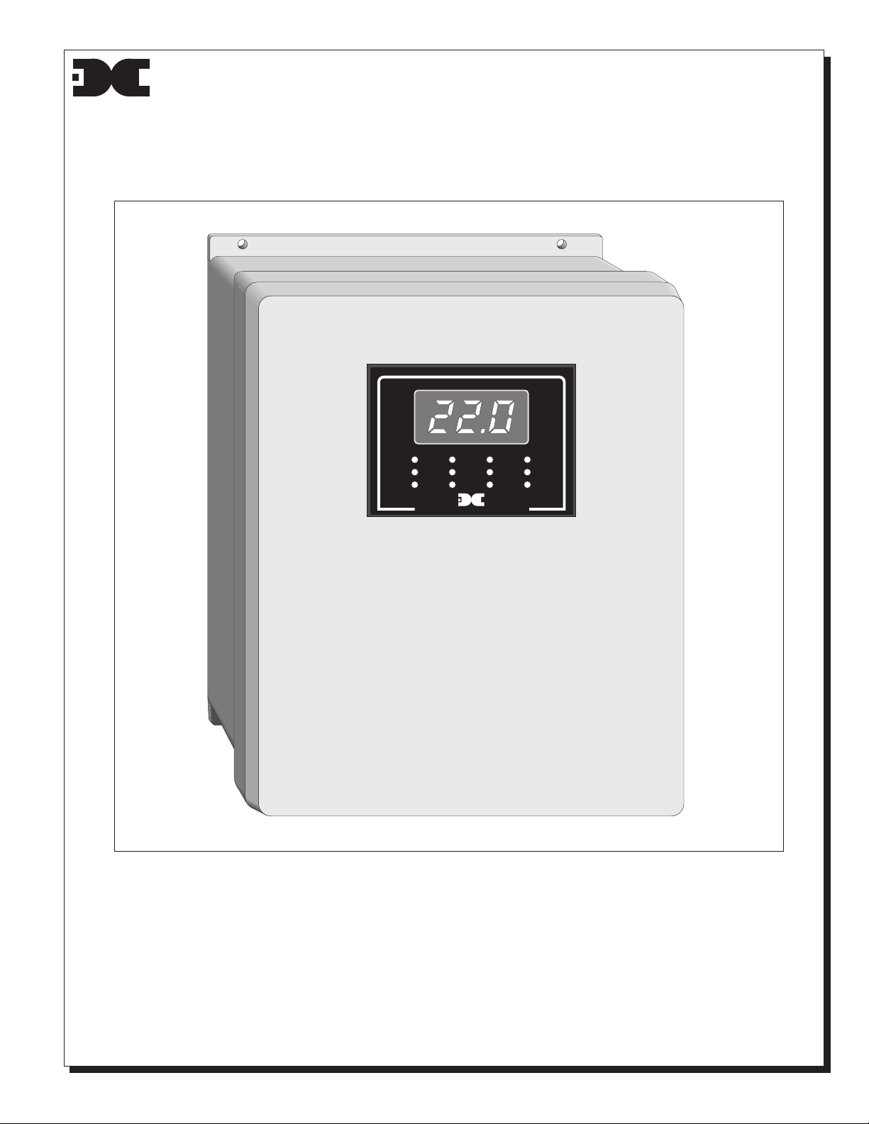
Detcon Model 100FB/200FB/400FB
Gas Detection System
Operator's Instruction Manual
Document #2475, December 1, 1999, Revision 1.0
400SS
1234
HIGH
LOW
FAULT
TEXASHOUSTON
detcon inc.
❏ 1.0 INTRODUCTION
Detcon Model 100FB/200FB/400FB gas detection system consists of 2 major assemblies:
1. The NEMA 4 fiberglass enclosure.
2. The remote mount gas sensor assemblies.
The NEMA 4 control enclosure is detailed in section 1.0 of the manual and applicable sensor
assemblies in section 3.0.
Model 100FB is a single channel monitor, Model 200FB is a dual channel and Model 400FB may be
configured with up to four channels of gas detection. Because of the similarities of each model, this
instruction manual will be used for all three and any differences will be described as neccesary.
Page 2

❏ 1.1 DESCRIPTION
Detcon Model 1/2/400FB is designed to serve as a host monitor for remote mount gas
detection sensor assemblies. The control enclosure is rated NEMA 4 non-hazardous and is
raintight suitable for outdoor location.
In its standard configuration the monitor is powered by an external 12 VDC power source
and includes the following features: an LCD indicator which displays the concentration of gas
in ppm or % by volume; discreet LED indicators which display alarm conditions for Fault,
Low and High alarms; Form C dry contacts (common, normally open and normally closed) for
low and high alarms; a rotory channel selector switch (Models 200FB & 400FB) will select
each channel and indicate that channel's gas conditions on the LCD display; an alarm disable
switch.
The monitor may include any of the following options as specified at time of order: an
internally mounted 117VAC power supply; an amber strobe light located on the top of the
monitor; a yelp-tone siren rated 100 db @ 10 feet; quick-connect plugs for power in and
sensor cables.
When purchased with the strobe and siren options the monitor comes pre-configured to
activate the strobe on a low alarm condition and the siren on a high alarm condition. The
alarm disable switch de-activates the siren during calibration.
❏ 1.2 SPECIFICATIONS
ELECTRICAL CLASSIFICATION: Nema 4 Non-Hazardous
DIMENSIONS: 9.25"W, 11.25"H, 5.5"D
16"H with strobe option
POWER: 12 VDC; optional 117 VAC
ALARMS: Fault, Low, & High
OPERATING TEMPERATURE RANGE: -40°F to +175°F
WEIGHT: 8 LBS
POWER CONSUMPTION:
< 8 Watts - Full Alarm Conditions
ADDITIONAL SENSOR POWER CONSUMPTION
< 1 Watt per sensor assembly
❏ 1.3 SENSOR POWER FUSE
Discreet PCB mounted microfuses (1/2 amp) located inside the monitor are used to protect
the sensors from voltage spikes. See the 1/2/400SS schematic in the back of this manual.
❏ 1.4 LOW / HIGH ALARMS
Comparitor circuitry is provided for Low and High alarms. Both alarms can be set in the range
from 0-100 ppm/% via control potentiometers located inside the monitor enclosure. Any
channel will activate the alarms regardless of the position of the channel selector switch. Alarm
conditions provide for discrete LED indicators as well as Form C dry contacts accessible via
quick connectors (common, normally open and normally closed) located on the back of the
controller circuit board. The connectors also provide a contact for 12VDC common.
An optional amber strobe for "Low" and a yelp-tone siren (100 db@ 10 feet) for "High" may be
purchased at time of order. The strobe and siren are shipped pre-wired.
❏ 1.5 FAULT SUPERVISION
Fault circuitry is provided for conditions resulting from an open signal loop or loss of power to
the sensor(s). Discreet LED indicators will illuminate during fault conditions.
❏ 1.6 ALARM DISABLE
An alarm disable switch on the front panel can be configured according to the users needs in
conjunction with the Form C dry contacts. When the monitor is ordered with optional strobe
and siren, the alarm disable switch is pre-wired to disable the siren only. Toggle up for disable.
Toggle Down for normal alarm function.
Detcon Model 1/2/400FB Gas Detection Monitor PG.2
Page 3
❏ 1.7 117VAC POWER SUPPLY OPTION
An optional 117VAC power supply is mounted on the base plate behind the control panel.
Monitors that come with the power supply option are pre-wired and 117VAC is applied to the
system via a lug-type terminal strip located on the base plate. Use the first three terminals labeled
L1 (Hot), L2 (Neutral) and Ground. The power supply output to the system is 12VDC. If the
quick-connect option is used, the 117VAC will be wired into the quick-connector as indicated in
latter text.
❏ 1.8 QUICK CONNECT OPTIONS
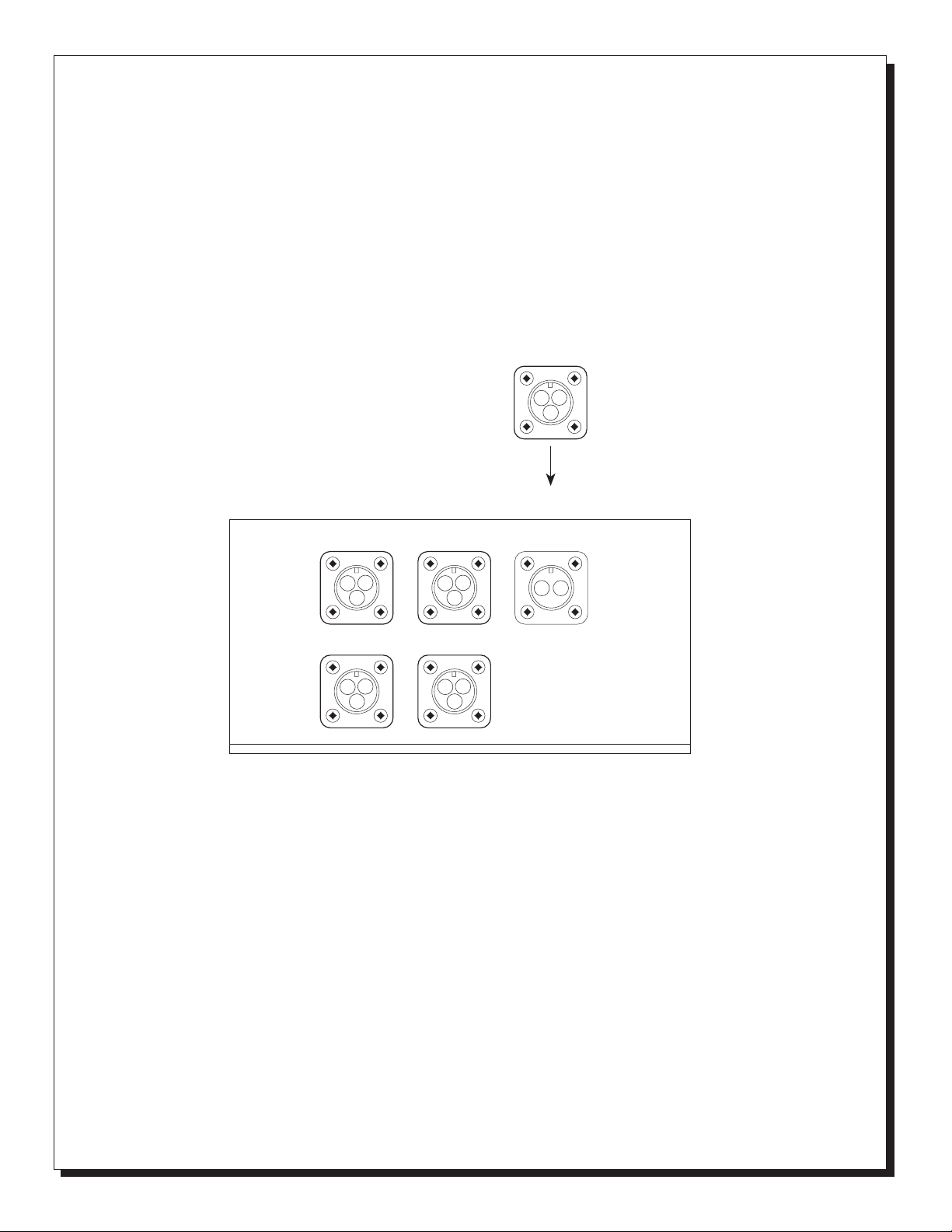
If equipped, the optional quick-connect plugs will be mounted on the bottom of the enclosure and
provide for entry of 12VDC (2 pin) or 117VAC (3 pin) as well as sensor connectors (3 pin) as
indicated in the illustration below. The quick connect plugs come pre-wirred internally.
OPTIONAL 117VAC
A = L1
B = L2
C = GROUND
A
C
B
FIG. 1 BOTTOM VIEW
SENSOR #1
A
C
B
SENSOR #3 SENSOR #4
A
C
B
SENSOR #2
A
C
B
A
C
B
A
B
DC POWER IN
A = +12 VDC
B = DC COMMON
SENSORS
A = +12 VDC
B = DC COMMON
C = MA SIGNAL
❏ 1.9 INSTALATION
01.
Securely mount the enclosure in accordance with figure #2.
02.
Connect the 12 VDC (or optional 117 VAC) to the lug-type terminal strip as shown in figure
#3 (Refer to figure 1 if you are using the optional quick-connect plugs). Be sure to observe
correct polarity as failure to do so may result in circuit damage on power up.
03.
Connect any alarms as neccessary to the lug-type terminal strip (Form C dry contacts)
located on the base plate as shown in figure 3. If you are using the strobe and siren option
this step is unneccessary because they are pre-wired.
04.
Connect the Sensors to the Connector plugs located on the back of the controller circut
board (+, – and milliamp) as shown in figure 4. If you are using the optional quick-connect
plugs, wire up the sensor(s) as shown in figure 1. Refer to installation and wiring detail of
remote mount sensor assemblies as detailed in section 3.0.
CAUTION: The sensor connector plugs, located on the back of the controller circuit board,
have a wire attached to them that goes to the rotary switch (200FB & 400FB). This wire must
remain in the same connector position so if you pull the connector off be sure to note which
channel it came off of. Failure to put the connector back in the same place will result in the
LCD display giving a reading of a different channel than is actually being monitored. If the
wires are out of order just note that the wire going to pin one of the rotary switch goes to W1
on the connector for channel 1 and so on.
Detcon Model 1/2/400FB Gas Detection System PG.3
Page 4
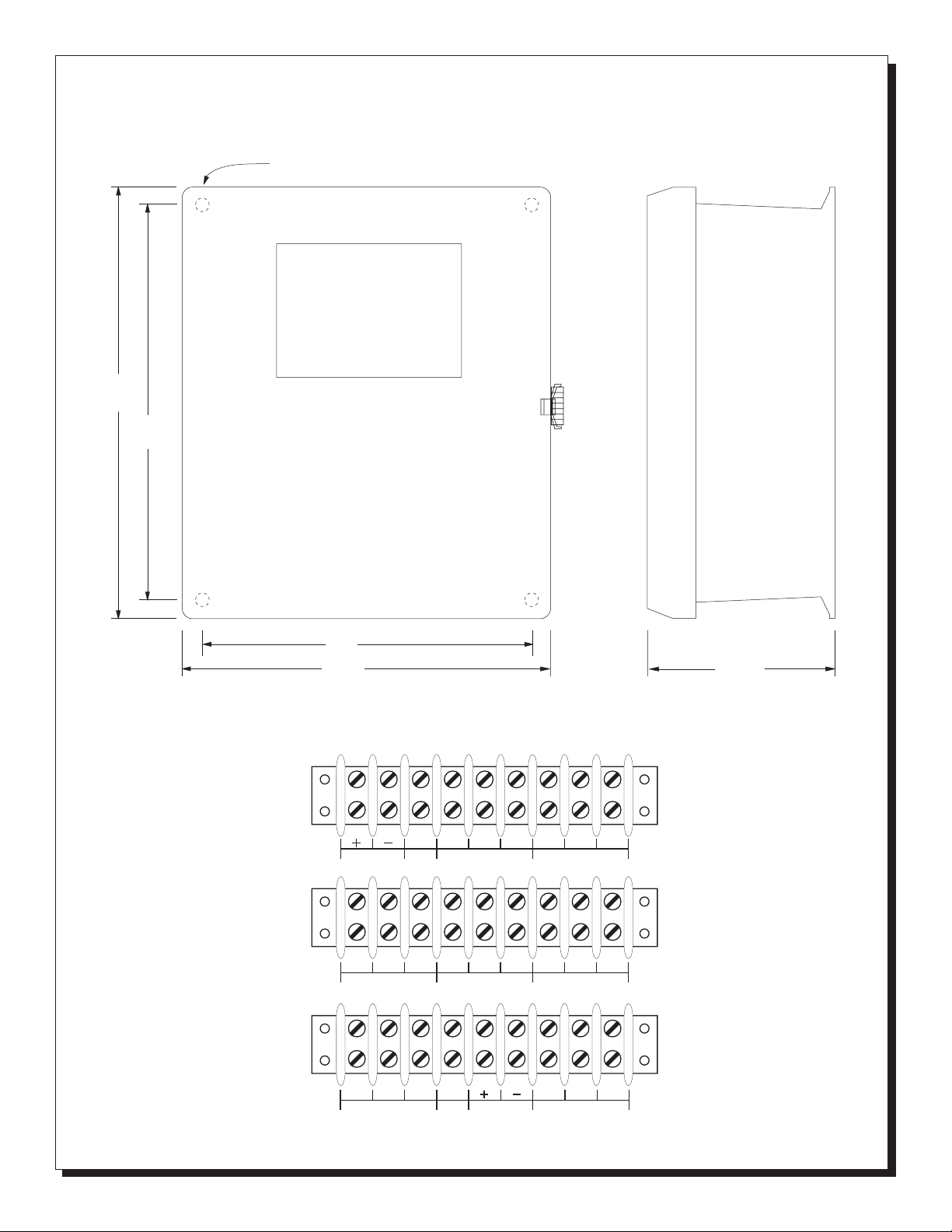
11.5"
Fig. 2 Mounting Dimensions
.312" DIA. MOUNTING HOLE
10.75"
12VDC
Version
117VAC
Version
117VAC
Version
with AC Output
6"
9.5"
Fig. 3 Terminal Strip
12VDC IN
117 VAC IN
L1 L2 GND
117 VAC IN
COM NO NC
FORM C CONTACTS LOW
COM NO NCL1 L2 GND
FORM C CONTACTS LOW
FORM C CONTACTS HIGH
FORM C CONTACTS HIGH
COM-L2 LOW-L1 HIGH-L1
DC IN
ALARMS OUT - SWITCHED VAC
5.5"
COM NO NC
COM NO NC
Detcon Model 1/2/400FB Gas Detection System PG.4
Page 5
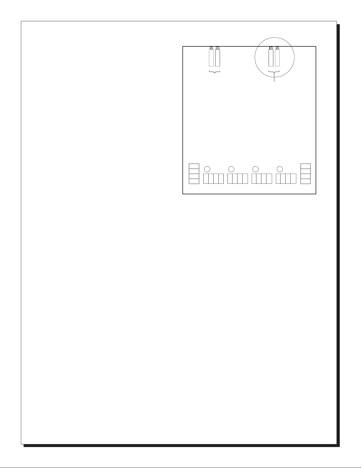
Fig. 4
Controller Circuit Board
Connector side view
HIGH
LOW
ALARM ADJUSTMENTS
ZERO
SPAN
CAUTION:
LCD ADJUSTMENTS
ARE FACTORY SET
❏ 1.10 START UP
Upon completion of all field wiring, apply
12 vdc (or optional 117 VAC) to the power
cable. Note that the LDC indicator
illuminates. Varying readings may occur
during sensor warm-up. Refer to section
LOW
ALARM
NO
NC
C
+V
GND
COM
CHANNEL 4F4CHANNEL 3F3CHANNEL 2F2CHANNEL 1
MA
SW1
+V
COM
MA
SW1
+V
COM
MA
SW1
F1
+V
COM
3.0 for additional sensor start-up detail.
❏ 1.11 SETTING ALARMS
NOTE: Refer to figure 4 for location of alarm set potentiometers.
To set the alarms you will apply a gas sample to the sensor on channel #1 and then adjust
the signal on that sensor with the "COARSE" span potentiometer until the reading on the
LCD display is equal to the point at which you want the alarm to fire. (See section 3.0 for
more detail on Detcon sensor assemblies).
NOTE: This procedure only needs to be done once and may be done off location in advance if
desired. This procedure will require that the sensor on channel 1 be recalibrated as
instructed in section 3.0 of this manual. Each time the alarms are changed using this
method be sure to recalibrate the sensor being used.
For example, if you want to set the low alarm at 10 ppm and the high alarm at 20 ppm follow
the steps below.
Apply a gas sample to the sensor at channel 1 and turn its "COARSE" span potentiometer
01.
until the LCD display reads 10.
Turn the "Alarm Set Low" potentiometer (located on back of the controller circuit board) until
02.
the low alarm LED on the front panel illuminates. If you have the strobe option, the strobe
will also activate.
Adjust the signal input (via Coarse potentiometer on sensor #1) above and below the low
03.
alarm set point to verify the exact firing point and make any further adjustments as
neccessary.
Next, repeat the same procedure for the High alarm (first set the LCD display to 20).
04.
Alarm set is complete. Both Low and High alarms may be independently set over the range
from 0-100 ppm. The alarm set points are common to all sensors connected to the enclosure.
NOTE: Alarms may be set without interfering with the Coarse potentiometer (on sensor
transmitter) by applying an appropriate gas sample and adjusting the Low and High alarm
potentiometers as the gas concentration passes the desired alarm set point as seen on the
LCD indicator. This method will not interfere with calibration but may be more tedius to
perform.
MA
SW1
HIGH
ALARM
NO
NC
C
GND
Detcon Model 1/2/400FB Gas Detection System PG.5
Page 6

❏ 1.12 LCD DISPLAY
NOTE: The LCD "Span" and "Zero" potentiometers (see figure #4) are used only to calibrate the
LCD display to a predetermined signal range. These controls should never be used as a
calibration "Span" and "Zero" while applying a known gas standard to the system. The
"Coarse", "Fine", and "Zero" potentiometers located on the sensor transmitter module are used
for this purpose.
The liquid crystal display is set to operate in a range of 0 to 100 ppm/% over a signal range
of 4 - 20 ma (4 ma = 000; 20 ma = 100). The LCD is calibrated at the factory and should not
require further adjustments. If fine tuning becomes necessary, refer to the "SPAN" (100) and
"ZERO" (000) potentiometers on the controller board inside the monitor enclosure. The display
may be calibrated by applying a 4 ma signal from the sensor (read 40 mvdc on sensor signal
test points) and adjusting the zero potentiometer on the monitor until the display reads "000".
Next apply a 20 ma signal from the sensor (read 200 mvdc on sensor signal test points) and
adjust the span potentiometer on the monitor until the display reads "100". Use the coarse
potentiometer on the sensor to adjust to a reading of 200 mvdc if neccessary. NOTE: the
sensor will need to be recalibrated if adjustments are made to the "Coarse" or "Fine" span
potentiometers on the sensor transmitter module. Because of the relationship between "Zero"
and "Span" LCD potentiometers the above procedure may need to be repeated a few times.
❏ 1.13 OPTIONAL 117 VAC - POWER SUPPLY FUSE
When optional 117 VAC power is used, a 12 VDC power supply is mounted inside the
control enclosure. On the power supply is mounted a line power fuse to prevent overvoltage
spikes to the circuits. Replacement fuse is a 1 amp, 3AG type slow blow .
❏ 1.14 WARRANTY
Detcon Inc., as manufacturer, warrants under intended normal use each new Model
100FB/200FB/400FB control enclosures to be free from defects in material and workmanship
for a period of one year from the date of shipment to the original purchaser. All warranties and
service policies are FOB the Detcon Inc. facility located in the Woodlands, Texas.
❏ 1.20 SPARE PARTS
PART # DESCRIPTION
0290 .5 amp micro fuse - box of 5
3539 100 db yelp tone siren
3544 Amber strobe light
3220 SPST power switch
3237 Rotary channel select switch
0297 1 amp (3AG) slow blow fuse - box of 5
Mailing address: P.O. Box 8067, The Woodlands, Texas 77387-8067 ❏ Phone: (281) 367-4100 ❏ Fax: (281) 292-2860
Shipping address: 3200 A-1 Research Forest Dr., The Woodlands, Texas 77381
 Loading...