

Page 1
DETCON INCORPORATED
Model 440 Remote Display System
Operator Instruction Manual
February 7, 2005, Document # 2969, Rev # 1
¤ Detcon Incorporated
3200 Research Forest Dr, The Woodlands, TX 77381
Phone 281.367.4100 • Fax 281.292.2860
Page 2

Model 440-RD Operator Manual Rev. 1 ii
Page 3

Table of Contents
1.0 Description.................................................................................................................................................1
2.0 System Operation.......................................................................................................................................2
3.0 Specifications.............................................................................................................................................3
4.0 Installation .................................................................................................................................................4
5.0 Start-up ......................................................................................................................................................8
5.1 Power Switch Selections.........................................................................................................................8
5.2 Applying Power......................................................................................................................................8
6.0 Remote Display Operation.........................................................................................................................9
6.1 Password Protection................................................................................................................................9
6.2 Navigating the Menus.............................................................................................................................9
6.3 Main Display Functions........................................................................................................................10
6.4 User-Interface Menu Functions ............................................................................................................10
NOTE: If the range is changed, the alarm levels will have to be reset!......................................................11
7.0 Options.....................................................................................................................................................14
7.1 Option for Battery Back-up Operation .................................................................................................14
8.0 Spare Parts...............................................................................................................................................14
9.0 Warranty..................................................................................................................................................14
Table of Figures
Figure 1 System Operational Diagram ............................................................................................................2
Figure 2 Mounting Diagram............................................................................................................................4
Figure 3 Power Input Schematic......................................................................................................................5
Figure 4 Mother Board Layout........................................................................................................................6
Figure 5 Control Board Layout........................................................................................................................7
Figure 6 Power Switch Configuration.............................................................................................................8
Figure 7 Password Protection SW1.................................................................................................................9
Figure 8 Front Panel User Interface...............................................................................................................10
Figure 9 Menu Flow Chart ............................................................................................................................11
Model 440-RD Operator Manual Rev. 1 iii
Page 4

Model 440-RD Operator Manual Rev. 1 iv
Page 5
1.0 Description
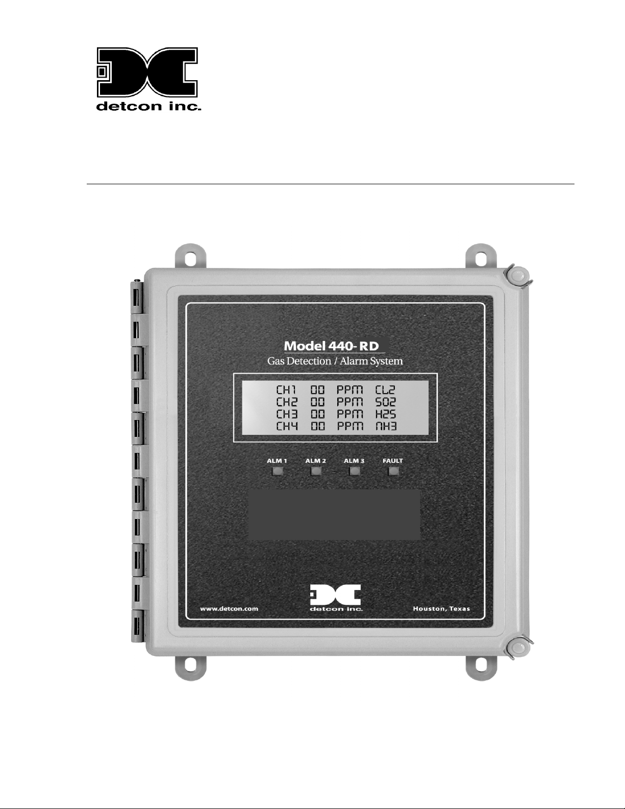
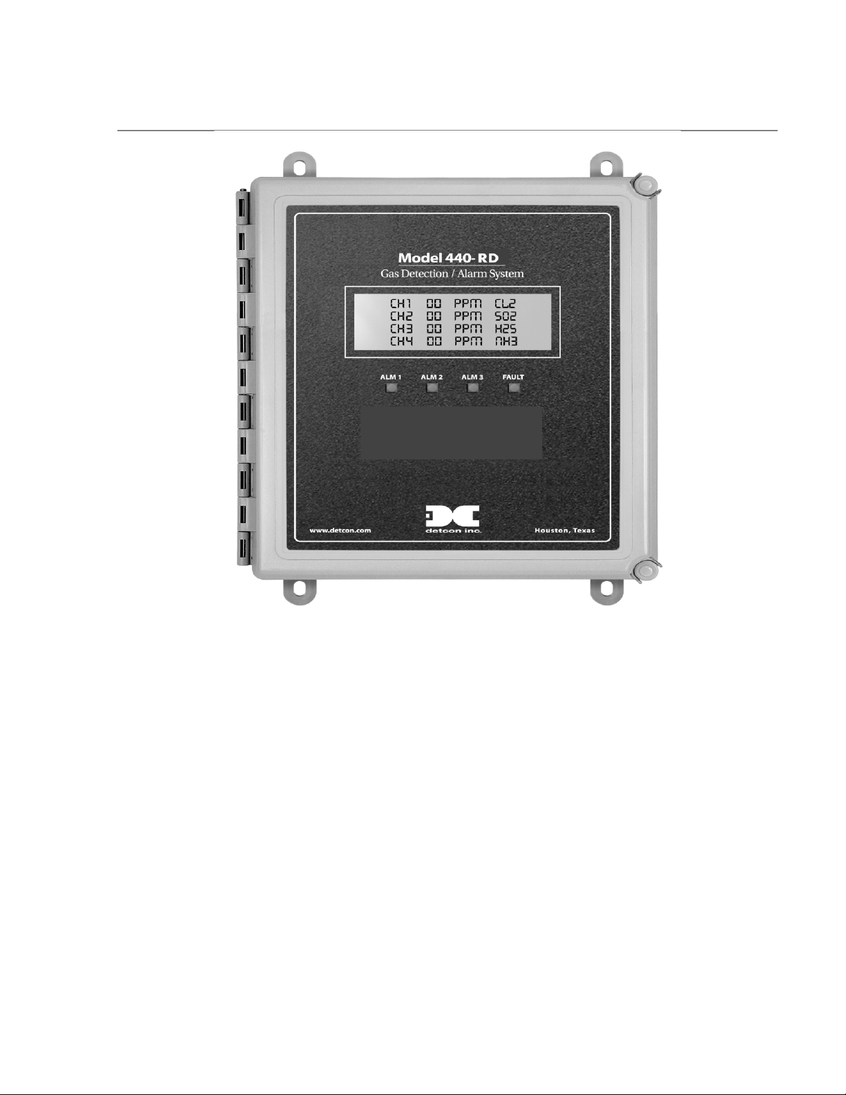
The Model 440-RD is a read only remote display unit designed to operate with input from Detcon Model
440 Controller. The Model 440-RD must be configured exactly as the Model 440 host controller to
function correctly.
The system displays real time channel information on a backlit LCD. Displayed information includes
channel number, gas type, and gas concentration. It also shows the current Alarm/Fault status via front
panel LED indicators.
The Model 440-RD has a built-in power supply, giving the user a multitude of power options. It can be
powered by either 115/230 VAC or 11.5 to 30 VDC, and has an optional one-hour battery backup in the
event of temporary power loss. It is housed in a Nema 4X waterproof enclosure.
The controller may be configured using the straightforward User Interface Menus or it can be uploaded
from a PC through the RS-232 serial communication port. The PC serial port connection and external
software can be used to download the recorded history for TWA, Peak and Alarm Events.
Model 440-RD Operator Manual Rev. 1 Page 1 of 14
Page 6
2.0 System Operation
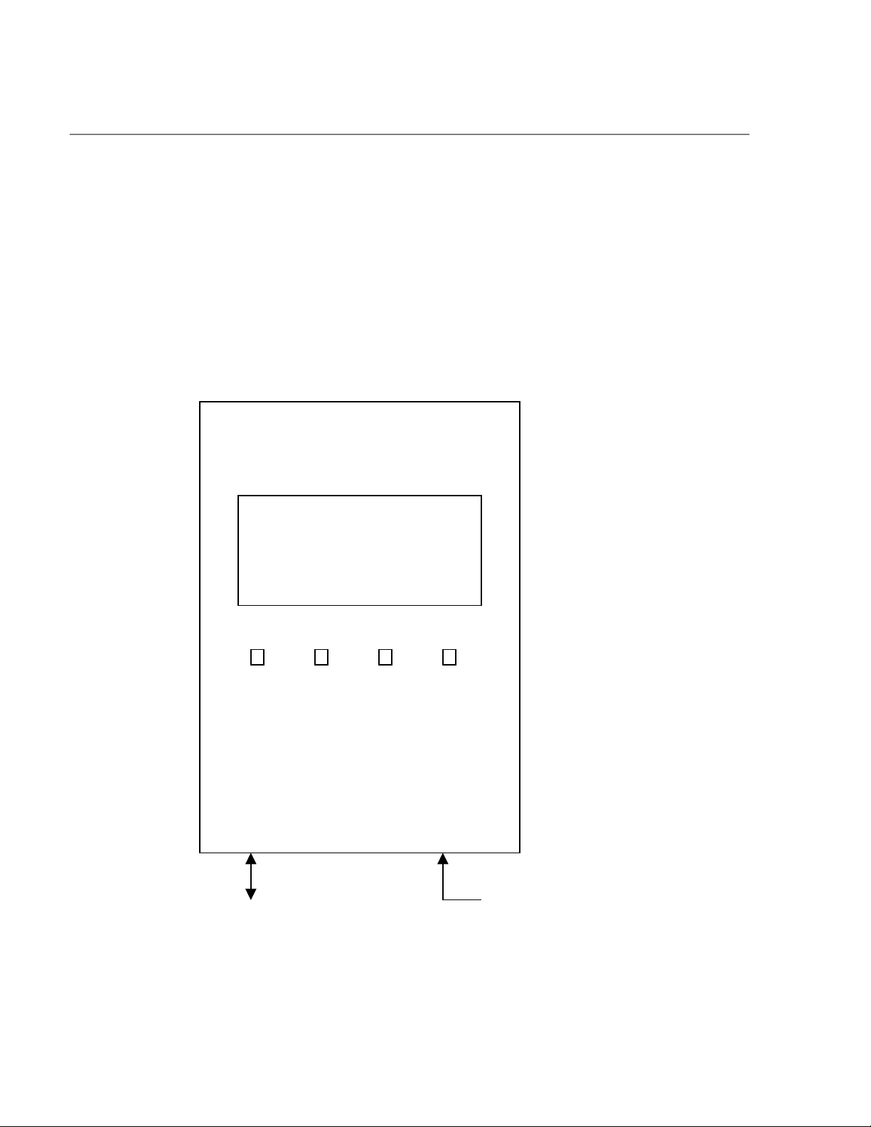
The Model 440-RD receives the data for remote display from the host Model 440 Controller. The system
displays current status information on its LCD display, which includes the gas channel #, current reading,
gas type, and alarm LED status.
SYSTEM OPERATION BLOCK DIAGRAMSCHEMATIC
MODEL 440-RD
Gas Detection/Alarm System
CH1 99 PPM CL2
CH2 80 PPM SO2
CH3 45 PPM H2S
CH4 00 PPM NH3
ALM 1 ALM 2 ALM 3 FAULT
RS- 485 Input From
Master Model 440
Controller
Input Power
115/230 VAC
11.5-30 VDC
Figure 1 System Operational Diagram
Model 440-RD Operator Manual Rev. 1.0.2 Page 2 of 14
Page 7

3.0 Specifications
Capacity
Sensor Inputs
Accuracy
Outputs
Electrical
Power Input
Power Consumption
Display
Electrical Classification
Dimensions
Physical
Operating Temperature Range
Warranty
4 Input Channels
Analog 4-20 mA or
± 1% Full Scale Range
None
115-230 VAC
11.5-30 VDC
Normal: 5 Watts @ 24 VDC
1”x5” Backlit LCD
NEMA 4X
11”W x 14”H x 6.5”D
-40F to +167F
-40C to +75C
Two year
Model 440-RD Operator Manual Rev. 1.0.2 Page 3 of 14
Page 8
4.0 Installation
4.1 Mounting and Cable Penetrations
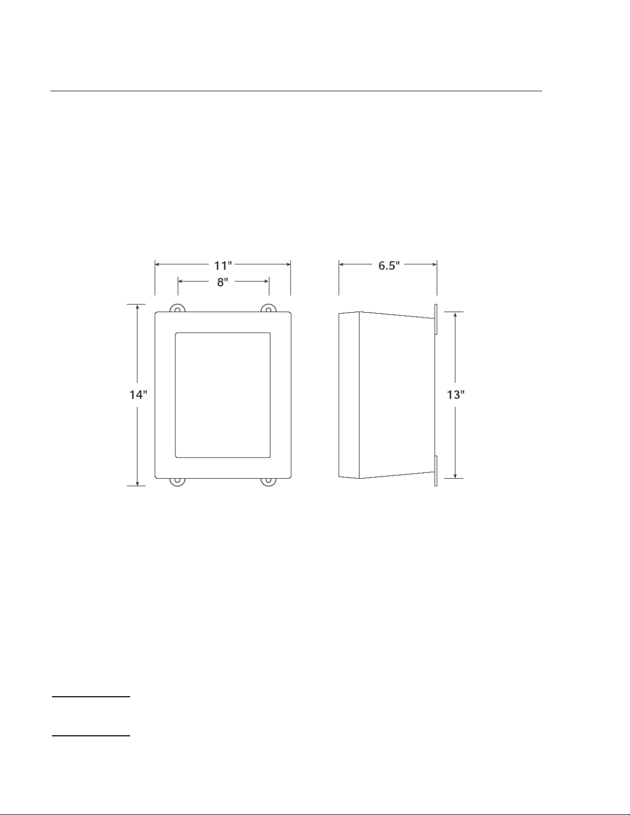
Securely mount the Model 440 RD enclosure per the mounting dimensions provided in Fig. 1.
Provide for suitable conduit/cable entries in the bottom of the enclosure. Keep AC power separate from
DC signals in conduit connections and runs.
Mounting Holes 5/16 Dia.
Figure 2 Mounting Diagram
4.2 Power and I/O Connections
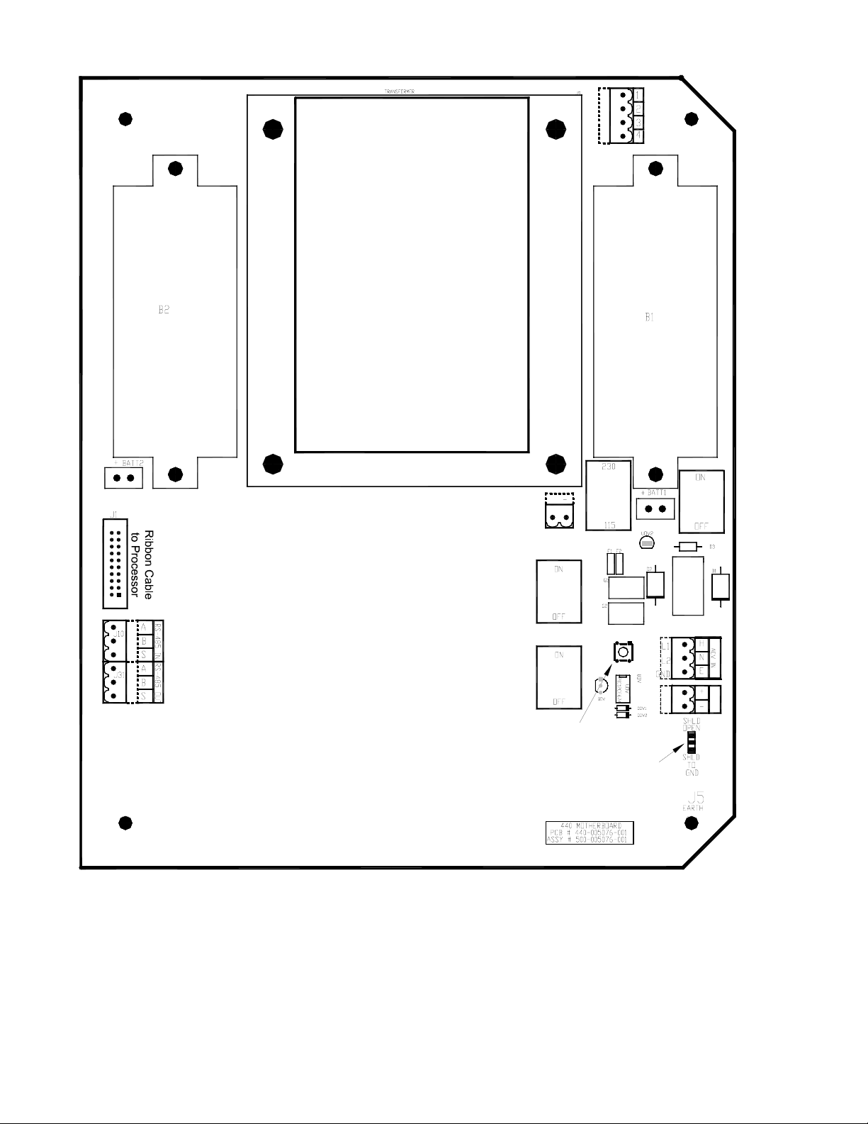
Power and I/O connections are made on the Motherboard PCB, which is mounted on the back of the
enclosure. Plug-in male connector terminal blocks are provided for customer wire terminations. This
connector style provides for quick disconnect convenience during replacement or servicing. (Refer to
Figure 4)
4.2.1 AC Power
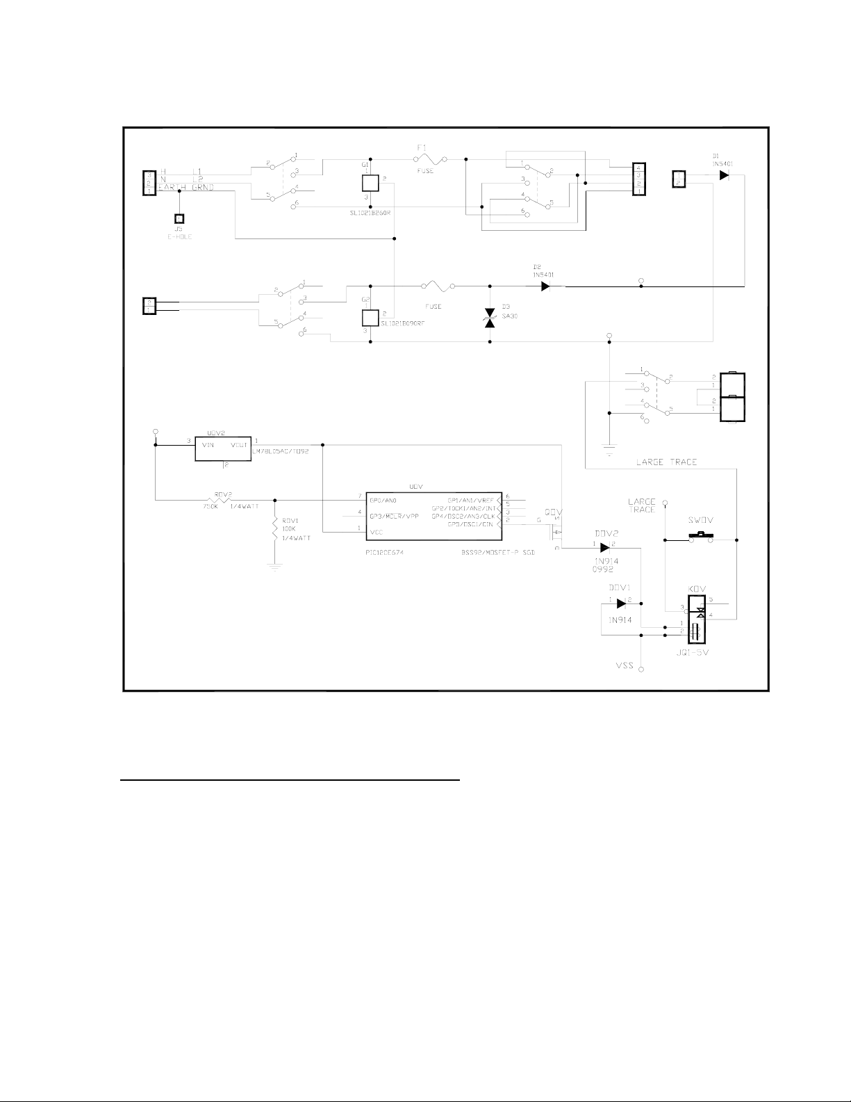
Connect 115 or 230 VAC input wiring to the terminals labeled “AC IN” in Figure 3 & Figure 4.
4.2.2 DC Power
For optional DC power input, connect 11.5 – 30VDC to the terminals labeled “DC IN” in Figure 3 &
Figure 4. This input can be used for primary power or back-up power in the event of a VAC power failure.
Model 440-RD Operator Manual Rev. 1.0.2 Page 4 of 14
Page 9
J2
External
VAC
Input
SW1
VAC ON/OFF
SW2
115VAC/220VAC
PS1
TO
DC POWER
SUPPLY
PS2
FROM
J8
External
VDC
Input
VIN
VDC +
VDC -
SW4
VDC ON/OFF
F2
MOTHER BOARD POWER INPUT
VIN
VSS
BATTERY ON/OFF
SW3
VIN
SWOV
BATTERY
RESTORE
BATT1
BATT2
Figure 3 Power Input Schematic
4.2.3 Serial Connection From Model 440 Controller
The serial connection from the Model 440 Controller should be terminated at the RS-485 input terminal of
the Model 440-RD motherboard PCB. See Figure 4. If applicable, the shield wire can be terminated at the
RS-485 connector labeled JP1 ‘SHLD TO GND’ on the motherboard PCB.
Model 440-RD Operator Manual Rev. 1.0.2 Page 5 of 14
Page 10
PS1
SW2
VOLTAGE
+
PS2
SW1
VAC
POWER
SWITCH
SW4
VDC
POWER
SWITCH
SELECT
Battery Restore
Switch
Jumper for RS-485
Shield to Earth
Grnd.
SW0V
SW3
BATTERY
EXTERNAL
AC IN
J2
EXTERNAL
DC IN
J8
JP1
Figure 4 Mother Board Layout
Model 440-RD Operator Manual Rev. 1.0.2 Page 6 of 14
Page 11
ON
OFF
Ribbon Cable to LCD
1234
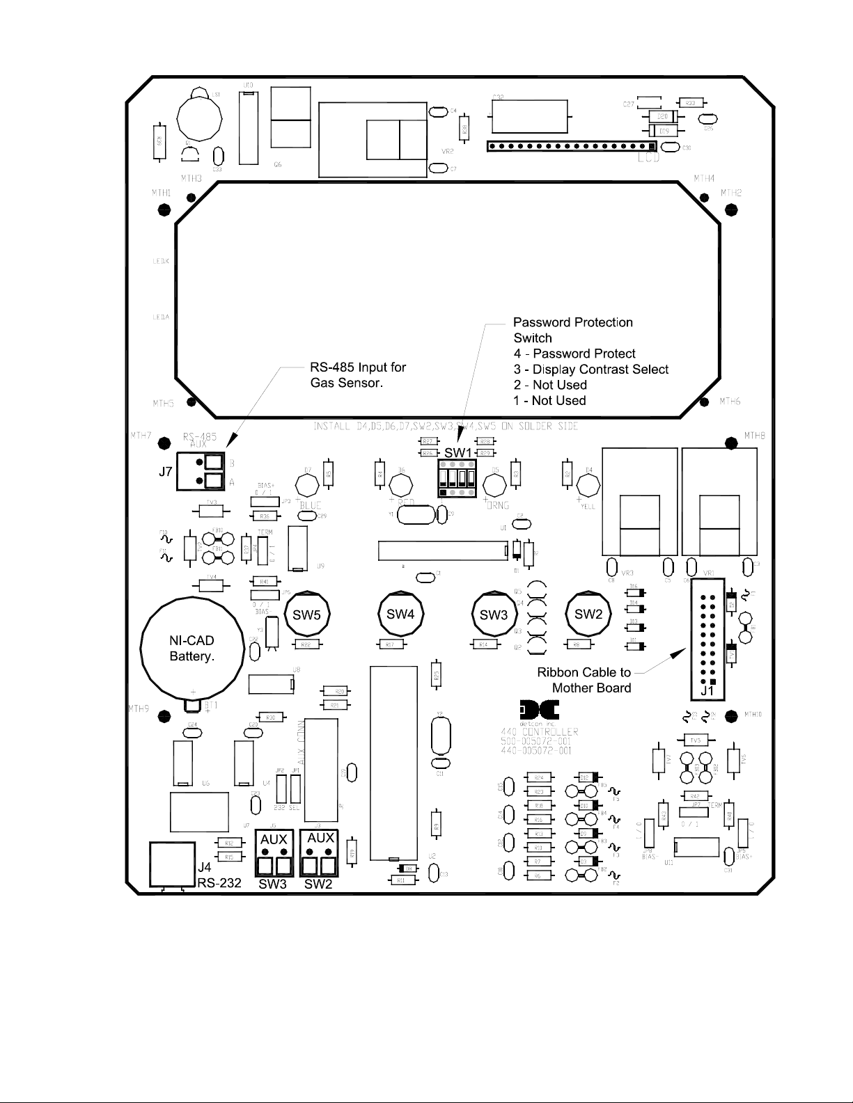
Figure 5 Control Board Layout
Model 440-RD Operator Manual Rev. 1.0.2 Page 7 of 14
Page 12
5.0 Start-up
NOTE: Before applying power, check and make sure that all the wiring connections and external devices
are installed correctly.
NOTE: Applying power with devices hooked up incorrectly may cause damage to the equipment.
5.1 Power Switch Selections
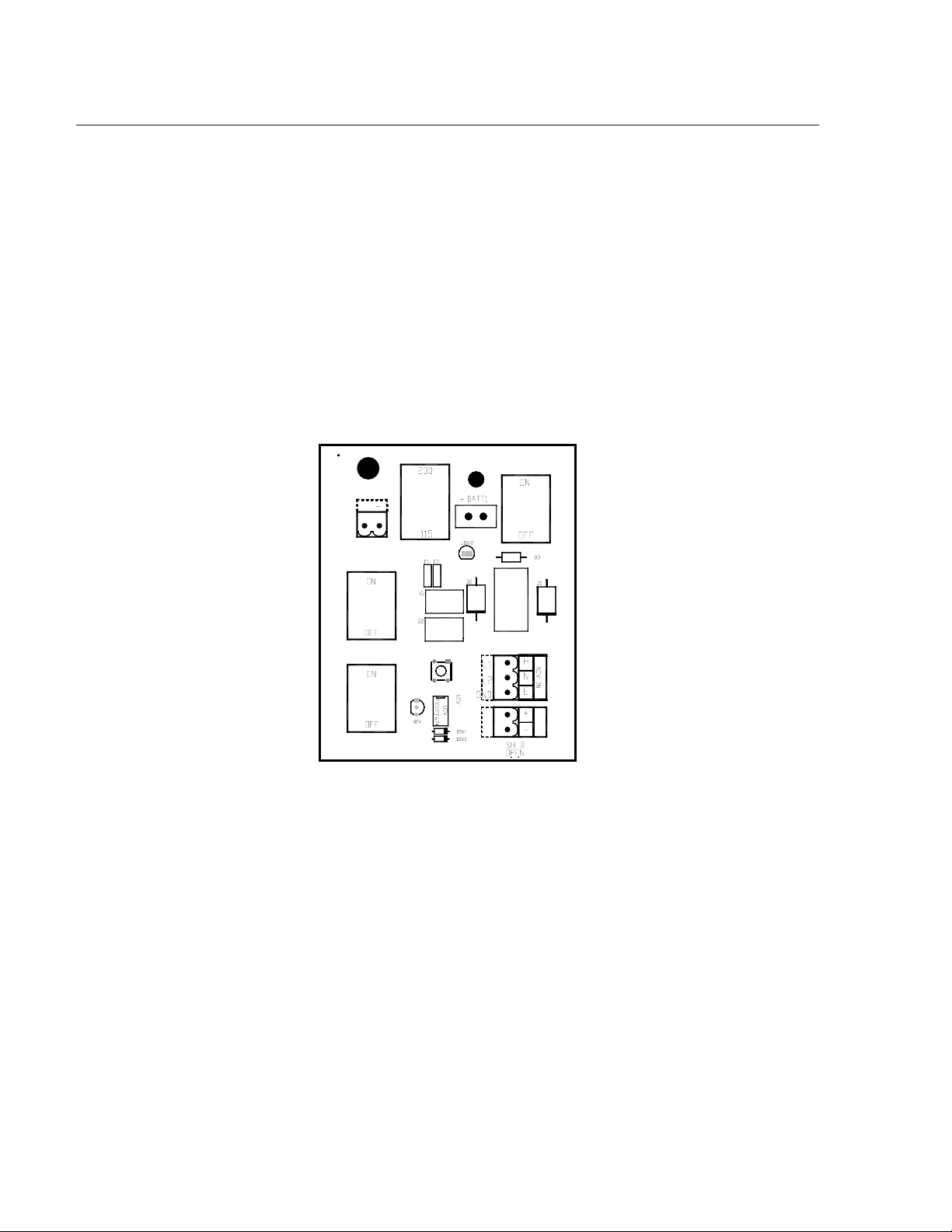
Refer to Figure 6. For AC power, locate the V-SELECT switch (SW2) and select the appropriate voltage
setting. If the unit will be powered by AC voltage only, then the VAC power switch should be turned to
the ON position, and insure the VDC power switch (SW4) is in the OFF position. If the unit will be
powered by the end-user’s DC source (or by a solar-battery power source), then the VDC power switch
should be turned to ON and insure the VAC power switch is in the OFF position. If the unit is to be
powered by AC and DC sources simultaneously, then both power switches should be in the ON position.
The switches are located on the Motherboard, shown in Figure 4
+
PS2
SW1
VAC
POWER
SWITCH
SW4
VDC
POWER
SWITCH
SW2
VOLTAGE
SELECT
SW0V
SW3
BATTERY
EXTERNAL
AC IN
J2
J8
EXTERNAL
DC IN
Figure 6 Power Switch Configuration
NOTE: The unit may have the internal battery back-up option. If so, there is a switch to leave the battery
connected or disconnected. The battery will normally be connected. See Section 8.1 for details on the
Battery Back-up Option.
5.2 Applying Power
Connect power per Section 4.2.
With the AC or DC power source connected, turn the applicable power switches to the ON positions.
Verify that the Main Display LCD comes up displaying gas readings on the display. The readings on the
Main Display LCD should match with those of the Model 440 Controller.
Model 440-RD Operator Manual Rev. 1.0.2 Page 8 of 14
Page 13
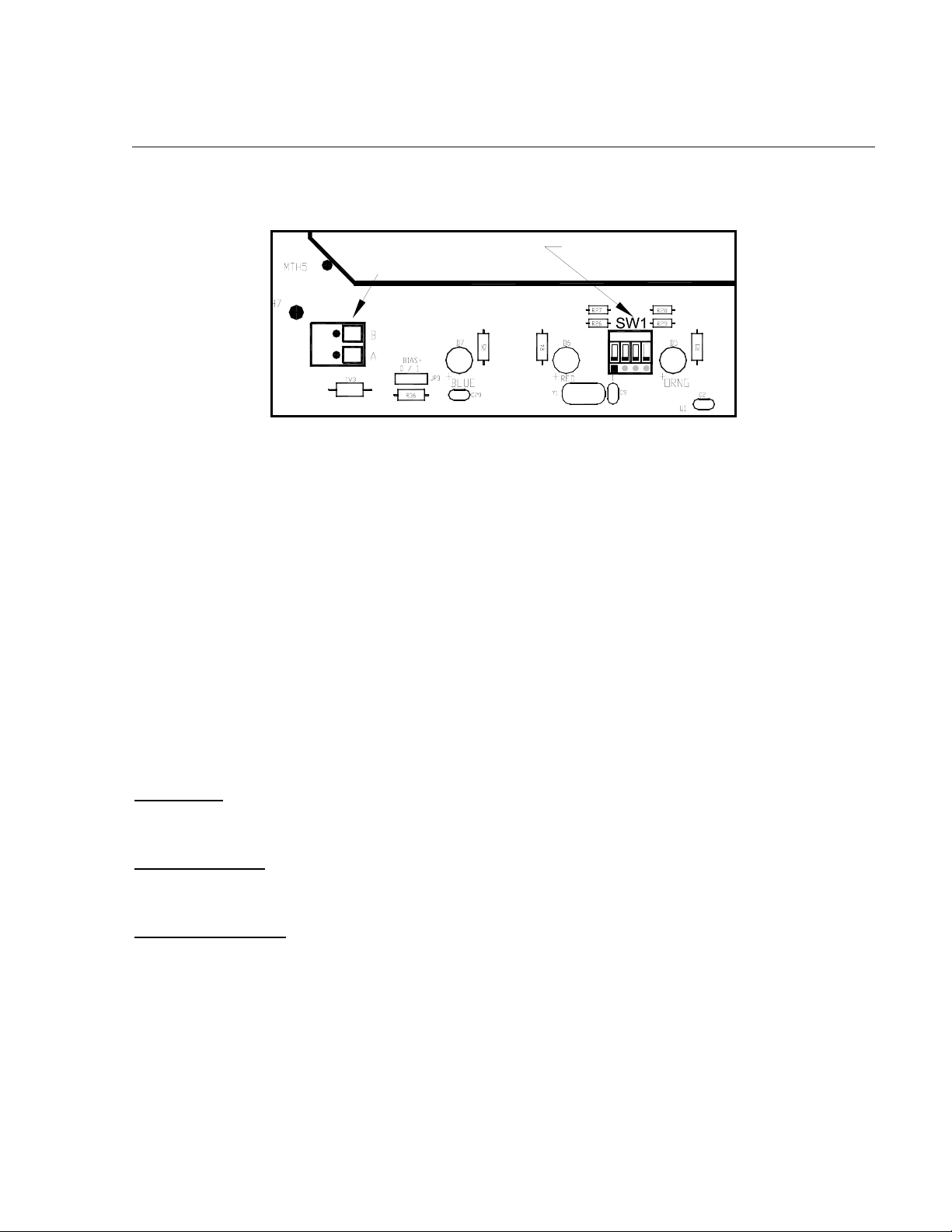
6.1 Password Protection
6.0 Remote Display Operation
RS-485 Input for
Gas Sensor.
part of Control Board
J7
Figure 7 Password Protection SW1
SW1 pos 4 - Password
Protect Switch
1 234
ON
OFF
Password protection is accomplished via a switch selection on the backside of the Controller PCB. (Figure
7 SW1.) With Switch 1 position 4 in the ON position, the Controller will be in Password Protected mode.
In this mode there is no access to the Menus. The only functionality provided for is the Main Display and
use of the Reset and Acknowledge functions. With Switch 1 – 4 in the OFF position, Password Protection
is turned off and there is complete access to the Menus.
6.2 Navigating the Menus
The user-interface for configuring gas channels and alarms is very simple to use. The menu text is
displayed on the backlit LCD and is interfaced via the four function keys located below it. These keys are
labeled from left to right: PROG, UP, DOWN, ENTER. The ENTER key is a multiple-use key that also
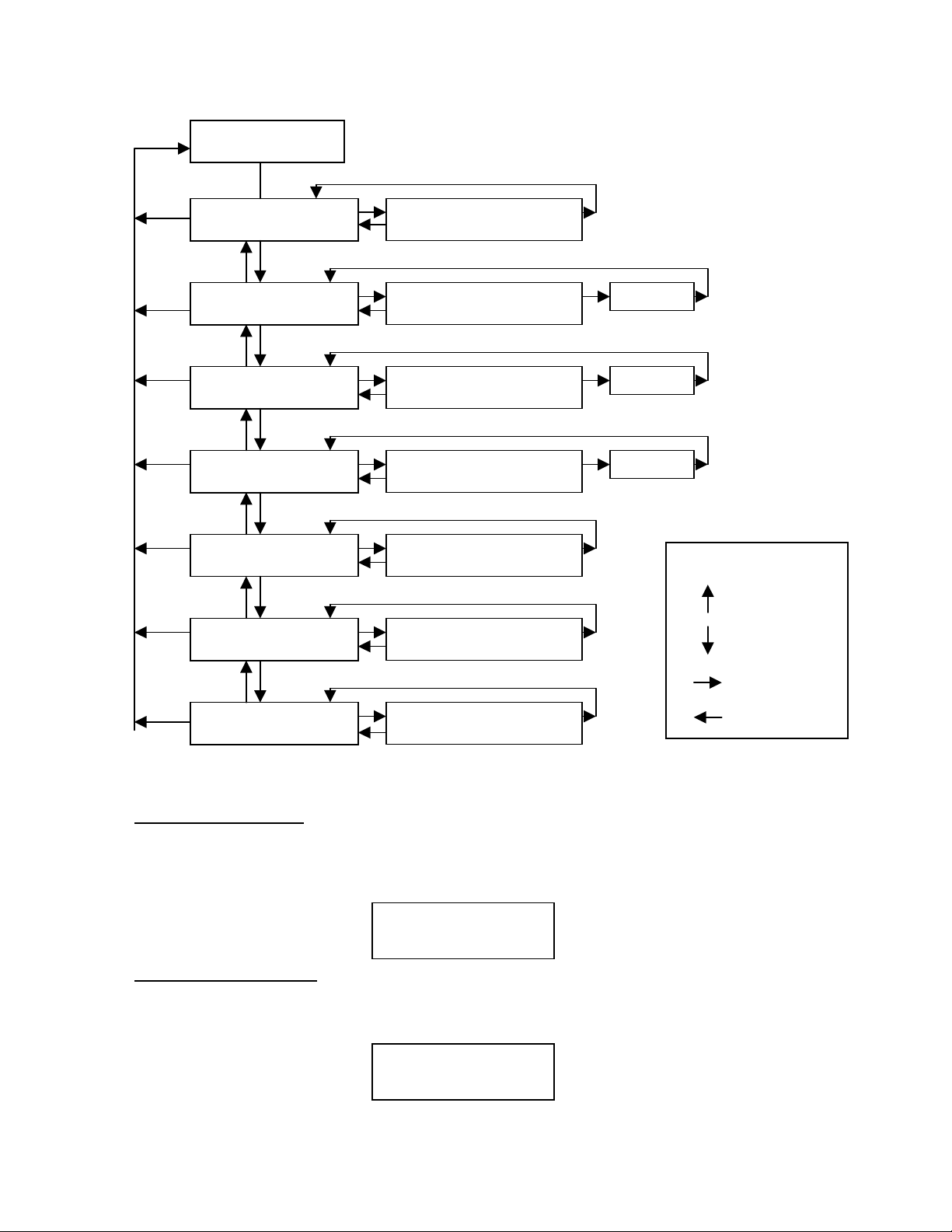
controls the Reset and Acknowledge relay functions. With reference to the Menu Flow Chart (See Figure
9) and the correct function key sequencing, is easy to learn how to navigate the menus, make changes, and
access the logged data.
PROG Key:
From the Main Display, the PROG key enters into the Main Menu. Once inside the Main Menu, the
PROG key acts as an “Escape” key that moves backwards in the Menu flow chart.
“Up Arrow” Key:
This key moves the user up the Main Menu flow chart. It is also used to change highlighted entries
within menu selections in the upward direction.
“Down Arrow” Key:
This key moves the user down the Main Menu flow chart. It is also used to change highlighted entries
within menu selections in the downward direction.
ENTER and Reset/Ack Key:
This key has a multiple-use purpose. The ENTER function is used to accept selections within all Menu
screens.
The Enter Key is also used to execute the Reset and Acknowledge functions. The Reset function releases
all latched relays if pressed after they have cleared the alarm/fault condition. The Acknowledge function
will disengage any silencable relays that are in a currently active state. This is typically used to silence
alarm annunciators, once the end-user has assessed the alarm condition.
Model 440-RD Operator Manual Rev. 1.0.2 Page 9 of 14
Page 14

Figure 8 Front Panel User Interface
NOTE: The controller automatically times out of Menu Mode and returns to the Main Display after 1
minute of inactivity. While in Menu Mode there are no updates to gas readings.
6.3 Main Display Functions
The Main Display is a 1”x 5” backlit LCD which has 4 lines by 24 characters. In normal operation “CH #
= XX ppm GAS” will bw displayed. If any channel is in any gas alarm condition, the “CH#” will
change to “ALM”. If any gas channels are in Fault, they will display “CH # = IN FAULT”. If any
channels are in CAL MODE, they will display as “CH # = In Cal MODE”. If any channels are not
communicating with sensors set up as serial input sensors, then they will display as “CH # = NO COMM”.
NOTE: The LCD has a backlight that will automatically turn off after 30 seconds of inactivity. The LCD
backlight will come on automatically as soon as any function key is pressed. This is a feature designed to
save on power.
6.4 User-Interface Menu Functions
The User-Interface is conducted via the Model 440-RD Front Plate shown above in Figure 8. The Menu
Flow Chart is shown below in Figure 9and is navigated using the function keys described above. UserInterface menu activity is conducted via the 1”x5” LCD and the four function keys. There are also four
LED indicators on the front panel that show alarm and fault relay status. The LED’s represent ALM 1
(green), ALM 2 (amber), ALM 3 (red) and FAULT (blue). There are 13 Main Menu entries and their
functional descriptions are discussed below.
Model 440-RD Operator Manual Rev. 1.0.2 Page 10 of 14
Page 15
N
ORMAL
OPERATION
Menu Flow Chart
MAIN MENU:
SET # OF CHANNELS
MAIN MENU:
SET CHANNEL RANGE
MAIN MENU:
SET CHANNEL TYPE
MAIN MENU:
SET CHANNEL ALARMS
MAIN MENU:
SET DATE & TIME
MAIN MENU:
VIEW TWA & PEAK
SET # OF CHANNELS
X
SET CHANNEL RANGE
CHX = #####
SET CHANNEL TYPE
CHX = XXXXXXX
SET CHANNEL
ALARMS
SET DATE AND TIME
MM/DD/YY HH:MM:SS
01/02/04 1200 - 1300
TWA #### PK #####
CH1 … X
CH1 … X
CH1 … X
KEY:
Up Arrow
Down Arrow
Enter
MAIN MENU:
VIEW ALARM RECS
ALM: MM/DD/YY
CHX- A1 ON HH:MM:SS
Figure 9 Menu Flow Chart
PROG
6.4.1 Set # of Channels
This menu entry allows the selection of the number of active channels. NOTE: the number of activated
channels can be less than (but not greater than) the controller’s maximum input capacity. It should match
the number of sensors you are hooking up to the controller. The menu appears as:
Set # of Channels:
1
6.4.2 Set Channel Range
This menu entry allows the selection of the Channel Range for each gas channel input. This is a scrolling
list from 1.00 up to 10,000 and covers all of the Detcon gas sensor range possibilities. This menu appears
as:
Set Channel Range:
CH1 = XX.X
NOTE: If the range is changed, the alarm levels will have to be reset!
Model 440-RD Operator Manual Rev. 1.0.2 Page 11 of 14
Page 16

6.4.3 Set Channel Type
This menu entry allows the selection of the Channel Type for each gas channel input. This is an alpha
numeric string that should encompass the units of measure followed by the chemical formula. For example
“ppm H2S” or “% LEL”. Use the up and down arrows to find the appropriate alpha numeric selection and
then use the ENTER button to select it. Enter the character string as is is expected to be displayed on the
Main Display.
NOTE: The character entry for a “space” is required and is available in the alphanumeric choices. All
character positions must have an entry including “spaces” for unused characters at the end of the string.
This menu appears as:
Set Channel Type:
CH1 = (PPM_H2S___)
6.4.4 Set Channel Alarms
This menu entry allows for the selection of the Channel Alarms for each gas channel input. These
represent your alarm level set-points. These set-points can be entered in 5% increments of the full-scale
range that has been selected for that channel. This menu entry will also set whether the alarm should be
ascending (right arrow) or descending (left arrow) by toggling. This menu appears as:
Set Channel Alarms:
CH1 – ALM1 = X.X Æ
Each gas channel has the capability to set up to 3 alarms (ALM1, ALM2, and ALM3).
NOTE: If there is no intention of using a gas alarm relay, a setting of 0.00 (zero) will make it inactive.
NOTE: Any channels that are in alarm will display “ALM” instead of “CH#” on the Main Display.
NOTE: If the channel range is changed, then the alarm set points must be re-entered!
6.4.5 Set Date and Time
This menu entry allows for the correct entry of the current date and time. The menu appears as:
Set Date and Time:
01/26/04_14:56:07
6.4.6 View TWA and Peak Readings
This menu entry is used to view the recorded TWA and Peak readings for the different gas channels. This
data can be viewed on the screen or can be downloaded via the RS232 port to a PC for graphical
presentation. Refer to Section 7.2 on instruction for using the downloading software provided with this
controller.
05/05/04 09:00 0001
CH1 TWA XX PK XX
This data is recorded every hour and formatted for display. It will report the date (05/05/04), time (09:00),
record # (0001), CH#, TWA and Peak reading as shown above.
Model 440-RD Operator Manual Rev. 1.0.2 Page 12 of 14
Page 17

6.4.7 View Event Records
This menu entry is used to view the recorded and saved Alarm, Fault and Maintenance records for the
different gas channels. This data can be viewed on the screen or can be downloaded via the RS-232 port to
a PC for graphical presentation. Refer to Section 7.2 on instruction for using the downloading software
provided with this controller.
05/06/04 09:00
0000 CH1 ALM1 ON
The data is formatted for display. It will report the date, time, record #, CH#, Event type and Event status.
All events will be logged with their start and stop times in the order that they occur.
Model 440-RD Operator Manual Rev. 1.0.2 Page 13 of 14
Page 18

7.0 Options
7.1 Option for Battery Back-up Operation
This option provides a nominal 1 hour of battery back-up power to the Gas Detection Alarm System. The
battery back-up system consists of two 12 VDC / 0.8 Amp-hour batteries in series, along with the requisite
low voltage cut-off circuitry. The batteries may be isolated during exchange or while in long-term storage
by using the battery disconnect switch shown in Figure 4. The low voltage cut-off circuit is designed to
disconnect the battery supply if the voltage is drained below 20 VDC. This is for battery protection
purposes. There is a battery restore switch on the Motherboard PCB, which must be pressed after the low
voltage cut-off is triggered. This is only necessary if the unit is going to be restored under battery power.
It is not necessary if restored under AC power.
8.0 Spare Parts
500-U05076-001 Motherboard PCB
500-U05072-LCD Controller Board PCB W/ LCD Display
000-003606-000 Replaceable Power Supply with cables
340-121200-000 12 VDC Batteries (Optional)
360-BR2330 Date/Time Clock NICAD Battery
9.0 Warranty
Detcon, Inc., as the manufacturer, warrants under intended normal use each new Model 140-N4X controller
to be free from defects in material and workmanship for a period of one year from the date of shipment to
the original purchaser. Should the controller fail to perform in accordance with published specifications
within the warranty period, return to Detcon, Inc., for necessary repairs or replacement. All warranties and
service policies are FOB the Detcon facility located in The Woodlands, Texas.
Model 440-RD Operator Manual Rev. 1.0.2 Page 14 of 14
 Loading...