

Page 1
Detcon Model 10/12 Control Card Test Fixture
Operators Instruction Manual
October 1, 2007 * Document 3385 * Revision 1.0
DETCON, Inc.
3200 Research Forest Dr., B uilding A-1
The Woodlands, Texas 77387
Ph. 713-559-9200 / Fa x 281-298-2868
www.detcon.com
Page 2

Model 10/12 Control Card Test Fixture
Table of Contents
1.0 Description
2.0 Features
3.0 Specificat ions
4.0 Operation
5.0 Test Fixtur e Ca li bration
6.0 Warran ty
Page 2 of 10
Page 3

Model 10/12 Control Card Test Fixture
1.0 Description
Detcon Model 10/12 Control Card Test Fixture is designed to test the operation of Detcon
Model Series 10 and Model Series 12 Control cards. Models covered are 10A, 10B, 10C,
12, 12A, 12B, and 12C.
2.0 Features
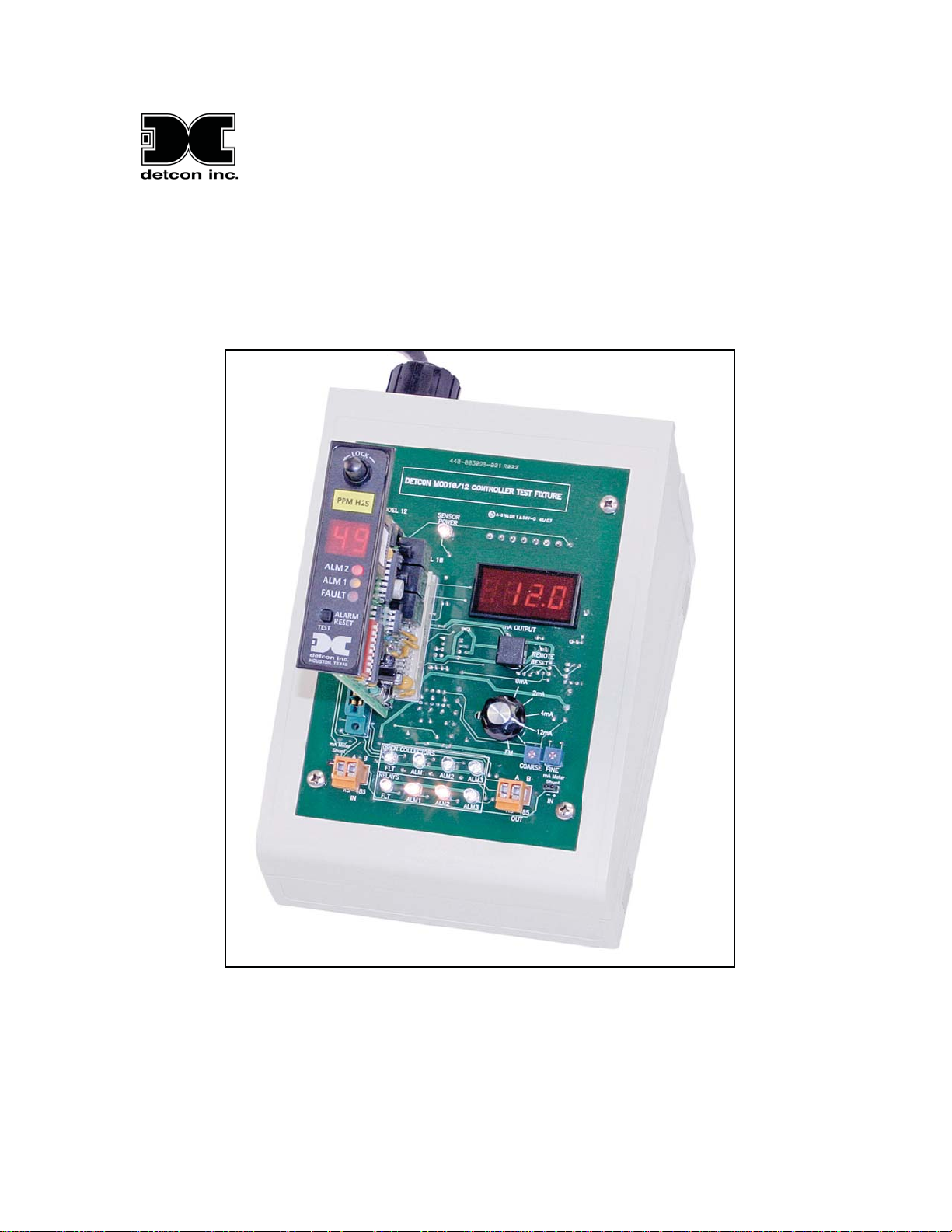
Refere n c e fig u r e 1 be low for feature locations.
Page 3 of 10
Page 4

Model 10/12 Control Card Test Fixture
1 - Internal power supply and power switch
2 - Sensor power indicator LED (D4)
3 - mA output digital LED meter
4 - Remote alarm reset switch (SW2)
5 - mA input range selector switch and Facilities Module selector (SW1)
6 - mA input adjustment potentiometers (R4 & R24)
7 - mA meter shunt - mA in (JP2)
8 - RS-485 output (TB2)
9 - Fault and alarm relay output LEDs (D5-8, D9-12)
10 - RS-485 Input (TB3)
11 - mA meter shunt - mA out (JP2)
12- Model 10 connector (J1)
13- Model 12 connector (J2)
3.0 Specifications
Compatible with the Following Models
Model 10A, 10B, 10C
Model 12, 12A, 12B, 12C
Input Power
100-240VAC, 50 / 60Hz
Power Consumption
< 17 Watts
Digital Current Meter
Accuracy: ± 0.3% FS
Warranty
Two year
Outputs
Serial RS-485 Modbus™
Inputs
Serial RS-485 Modbus™
4.0 Operation
Before using the test fixture, the technician should first be familiar with the operation of
Detcon Model 10 and/or Model 12 series control cards. The technician should review the
applicable control card instruction manual(s) for detailed operating instructions.
NOTE 1: The test fixture is designed to be used with only one control card at a time,
either the Model 10 or the Model 12. Plugging more than one control card into the test
fixture at the same time (J1 and J2) will cause erroneous readings.
NOTE 2: Reference Figure 1 for location of test fixture components. Before starting
verify that SW1 is in the “4mA” position and that both mA meter shunt jumper tabs (JP2
& JP3) are installed.
Page 4 of 10
Page 5

Model 10/12 Control Card Test Fixture
Require tools:
Digital Volt-Ohm Meter (DVM)
Jewelers screwdriver
NOTE: These instructions cover testing of the main features of the Model 10 and Model
12 control cards. See the applicable instruction manual for a complete list of program
features and detailed operating procedures.
4.1 Model 10A and 10B Control Cards
NOTE: These instructions are based on the assumption that the Model 10 control card has
already been calibrated and basic alarm options have been configured.
1 - Turn the power switch on. Note that the digital mA Output LED meter illuminates
with a reading of 00.0.
2 - Plug the Model 10 control card into J1.
3 - Note that the Sensor Power LED (D4) is illuminated. This indicates power from the
control card to the sensor.
4 - Verify mA input and output using the mA input range selector switch (SW1).
SW1 Position Mod 10 mA Output Display (±0.1)
0mA SF (sensor fault) 0.00
2mA SF (sensor fault) 02.0
4mA 0 04.0
12mA 50 (±1) 12.0
Variable R4 & 24 99 Flashing 20.0
Note: The Variable mA position is normally set for 20.0 mA input. These potentiometers
can be adjusted to cause the mA input to cover the full range from 0 to 21+ mA. This is
useful for checking alarm set points and over-range conditions. The potentiometers are
turn. Center the fine potentiometer and adjust the coarse potentiometer to where you want
the mA input signal to be. Use the fine potentiometer for fine adjustments.
5 - Check alarm relay outputs.
NOTE: Model 10 control cards are 2 alarm devices. Disregard the alarm 3 (D8) LED on
the test fixture for this test.
FLT, ALM1, and ALM2 LEDs (D5, D6, & D7) will be dimly illuminated when not in
alarm. This dim illumination indicates that the normally closed contacts are operating
properly.
Page 5 of 10
Page 6

Model 10/12 Control Card Test Fixture
Turn SW1 clockwise until ALM1 and ALM2 LEDs on the Model 10 illuminate. Verify
that the corresponding alarm LEDs on the test fixture (D6 and D7) also illuminate.
Return SW1 to the “4mA” position.
If alarms on the control card are programmed for latching, push the alarm reset button to
deactivate. Test the Remote Reset butt on on the test fixture by reactivating the (latched)
alarms and then use SW2 to reset.
Turn SW1 to the 0 mA position and verify fault LEDs illuminate on the control card as
well as the test fixture (D5).
4.2 Model 10C Control Card
NOTE: These instructions are based on the assumption that the Model 10C control card
has already been calibrated and basic alarm options have been configured.
1 - Turn the power switch on. Note that the digital mA Output LED meter illuminates
with a reading of 00.0.
2 - Plug the Model 10C control card into J1. The firmware version will display on power
up.
3 - Note that the Sensor Power LED (D4) is illuminated. This indicates power from the
control card to the sensor.
4 - Verify mA input and output using the mA input range selector switch (SW1).
SW1 Position Mod 10C mA Output Display (±0.1)
0mA SENS 0.00
2mA CAL 02.0
4mA 00 04.0
12mA 50 (±1) 12.0
Variable R4 & 24 100 20. 0
Var iable R4 & 24 100 f lashing 20. 1 or greater
Note: The Variable mA position is normally set for 20.0 mA input. These potentiometers
can be adjusted to cause the mA input to cover the full range from 0 to 21+ mA. This is
useful for checking alarm set points and over-range conditions. The potentiometers are
turn. Center the fine potentiometer and adjust the coarse potentiometer to where you want
the mA input signal to be. Use the fine potentiometer for fine adjustments. To test
flashing over-range, adjust the fine potentiometer to achieve an output greater than 20.0
mA.
Page 6 of 10
Page 7

Model 10/12 Control Card Test Fixture
5 - Check alarm relay outputs.
NOTE: Model 10C control cards are 2 alarm devices. Disregard the alarm 3 (D8) LED on
the test fixture for this test.
FLT, ALM1, and ALM2 LEDs (D5, D6, & D7) will be dimly illuminated when not in
alarm. This dim illumination indicates that the normally closed contacts are operating
properly.
Turn SW1 clockwise until ALM1 and ALM2 LEDs on the Model 10C illuminate. Verify
that the corresponding alarm LEDs on the test fixture (D6 and D7) also illuminate.
Return SW1 to the “4mA” position.
If alarms on the control card are programmed for latching, push the RESET button to
deactivate. Test the Remote Reset butt on on the test fixture by reactivating the (latched)
alarms and then use SW2 to reset. The control card display will indicate “EXT ALM
RST”.
Turn SW1 to the 0 mA position and verify fault LEDs illuminate on the control card as
well as the test fixture (D5).
6 - Open Collector LEDs. The open collector LEDs (D9, D10, and D11) should
illuminate with the corresponding alarm LED located under them. The open collectors do
not have a dim state when alarms are off.
4.3 Model 12, 12A and 12B Control Cards
NOTE: These instructions are based on the assumption that the Model 12 control card has
already been calibrated and basic alarm options have been configured.
1 - Turn the power switch on. Note that the digital mA Output LED meter illuminates
with a reading of 00.0.
2 - Plug the Model 12 control card into J2.
3 - Note that the Sensor Power LED (D4) is illuminated. This indicates power from the
control card to the sensor.
4 - Verify mA input and output using the mA input range selector switch (SW1).
SW1 Position Mod 10 mA Output Display (±0.1)
0mA 000 03.6
2mA 000 03.6
4mA 000 04.0
12mA 50 (±1) 12.0
Page 7 of 10
Page 8

Model 10/12 Control Card Test Fixture
Var iable R4 & 24 100 Flashing 20.0
Note: The Variable mA position is normally set for 20.0 mA input. These potentiometers
can be adjusted to cause the mA input to cover the full range from 0 to 21+ mA. This is
useful for checking alarm set points and over-range conditions. The potentiometers are
turn. Center the fine potentiometer and adjust the coarse potentiometer to where you want
the mA input signal to be. Use the fine potentiometer for fine adjustments.
5 - Check alarm relay outputs.
Turn SW1 clockwise until ALM1, ALM2, and ALM3 LEDs on the Model 12 illuminate.
Verify that the corresponding alarm LEDs on the test fixture (D6, D7, and D8) also
illuminate. Return SW1 to the “4mA” position.
If alarms on the control card are programmed for latching, push the alarm reset button to
deactivate. Test the Remote Reset butt on on the test fixture by reactivating the (latched)
alarms and then use SW2 to reset.
Turn SW1 to the 0 mA position and verify fault LEDs illuminate on the control card as
well as the test fixture (D5).
6 - Alarm Disable. Turn SW1 clockwise until ALM1, ALM2, and ALM3 LEDs on the
Model 12 and Test Fixture panel illuminate. On the model 12, move the alarm disable
switch to the disable (down) position. This should cause the fault LEDs to illuminate on
the Model 12 and the Test fixture. The alarm LEDs on the test fixture (D6, D7, and D8)
should go off. Return the alarm disable switch to the “Able” position and SW1 to the
4mA position.
4.4 Model 12C Control Card
NOTE: These instructions are based on the assumption that the Model 12C control card
has already been calibrated and basic alarm options have been configured.
1 - Turn the power switch on. Note that the digital mA Output LED meter illuminates
with a reading of 00.0.
2 - Plug the Model 12C control card into J2.
3 - Note that the Sensor Power LED (D4) is illuminated. This indicates power from the
control card to the sensor.
4 - Verify mA input and output using the mA input range selector switch (SW1).
SW1 Position Mod 12C m A Output Display (±0.1)
0mA SENS 0.00
Page 8 of 10
Page 9

Model 10/12 Control Card Test Fixture
2mA CAL 02.0
4mA 00 04.0
12mA 50 (±1) 12.0
Var iable R4 & 24 100 20.0
Var iable R4 & 24 100 f lashing 20. 1 or greater
Note: The Variable mA position is normally set for 20.0 mA input. These potentiometers
can be adjusted to cause the mA input to cover the full range from 0 to 21+ mA. This is
useful for checking alarm set points and over-range conditions. The potentiometers are
turn. Center the fine potentiometer and adjust the coarse potentiometer to where you want
the mA input signal to be. Use the fine potentiometer for fine adjustments. To test
flashing over-range, adjust the fine potentiometer to achieve an output greater than 20.0
mA.
5 - Check alarm relay outputs.
Turn SW1 clockwise until ALM1, ALM2, and ALM3 LEDs on the Model 12C
illuminate. Verify that the corresponding alarm LEDs on the test fixture (D6, D7, and
D8) also illuminate. Return SW1 to the “4mA” position.
If alarms on the control card are programmed for latching, push the RESET button to
deactivate. Test the Remote Reset butt on on the test fixture by reactivating the (latched)
alarms and then use SW2 to reset. The control card display will indicate “EXT ALM
RST”.
Turn SW1 to the 0 mA position and verify fault LEDs illuminate on the control card as
well as the test fixture (D5).
6 - Open Collector LEDs. The open collector LEDs (D9, D10, D11, and D12) should
illuminate with the corresponding alarm LED located under them.
4.5 Other Features
1 - mA Meter Shunt IN (JP2). Removing the jumper tab on JP2 will cause the mA input
signal to the control card to become open. A current meter can be used to measure the
input current with the jumper tab removed. Be sure the jumper tab is installed for normal
operation.
2 - mA Meter Shunt OUT (JP3). Removing the jumper tab on JP2 will cause the mA
output signal to the mA OUTPUT meter on the test fixture to become open. A current
meter can be used to measure the output current with the jumper tab removed. Be sure the
jumper tab is installed for normal operation.
3 - Facilities Module (FM) The Facilities Module (FM) is a product variation of the
Page 9 of 10
Page 10

Model 10/12 Control Card Test Fixture
Model 10C and 12C control cards. The Model 10C Facilities Module runs different
firmware than a Model 10C control card and has a piggy-back board and different face
plate and label. Likewise, there is a Model 12C Facilites Module that is a variation on the
Model 12C control card. The Facilites Module makes use of two RS485 ports. The Model
10C control card makes use of only the RS485 OUT port. To make use of the other
RS485 port, the IN port, the Model 10C and Model 12C share backplane connector pins
with analog inputs and outputs.
Rotary Switch FM Position The Facilities Module (FM) does not use analog inputs nor
analog outputs. The FM has an RS485 Input Port that shares backplane connector pins
with the analog input and analog output. When the Tester's rotary switch is in the FM
position, the analog input signal and analog output signal is disconnected from the
backplane pins. Instead these backplane pins are connected to the two-pin screw
terminals marked RS485 IN while the switch is in the FM position. The analog input
signal generated by the tester and the analog output to the panel meter are not connected
to anything while the rotary switch is in the FM position.
4 - RS485 OUT. The Model 10C and Model 12C control cards generate a response to a
Modbus Master that polls the cards on this RS485 signal pair. The Master must be set to
poll the Modbus Address Identification (ID) of the control card, and at the Baud Rate and
Parity that is set in the control card, in order to get a response.
5 - RS485 IN. This is only used by the Facilities Module (FM) and not used with the
Model 10 or 12 control cards. The FM serves as a Modbus Master that can poll a list of
Modbus devices, typically control cards, and can output to MOD 10C/12C Relay Output
Cards (ROC). While the Rotary Switch is not in the FM position, this screw terminal
connector is not connected to the board under test.
5.0 Test Fixture Calibration
The Model 10-12 Control Card Test Fixture is calibrated at the Detcon factory. SW1
range adjustment potentiometers are factory set and should not be adjusted by the user. If
calibration is required, return the test fixture to Detcon for calibration.
6.0 Warranty
Detcon, Inc., as manufacturer, warrants each Model 10-12 Control Car d Test Fixture for
a two year period under the conditions described as follows: The warranty period begins
on the date of shipment to the original purchaser and ends two years thereafter. Should
the test fixture fail to perform in accordance with published specifications within the
warranty period, return it to Detcon, Inc., 3200 A-1 Research Forest Dr., The Woodlands,
Texas 77381, for necessary repairs or replacement.
Page 10 of 10
 Loading...