

Page 1
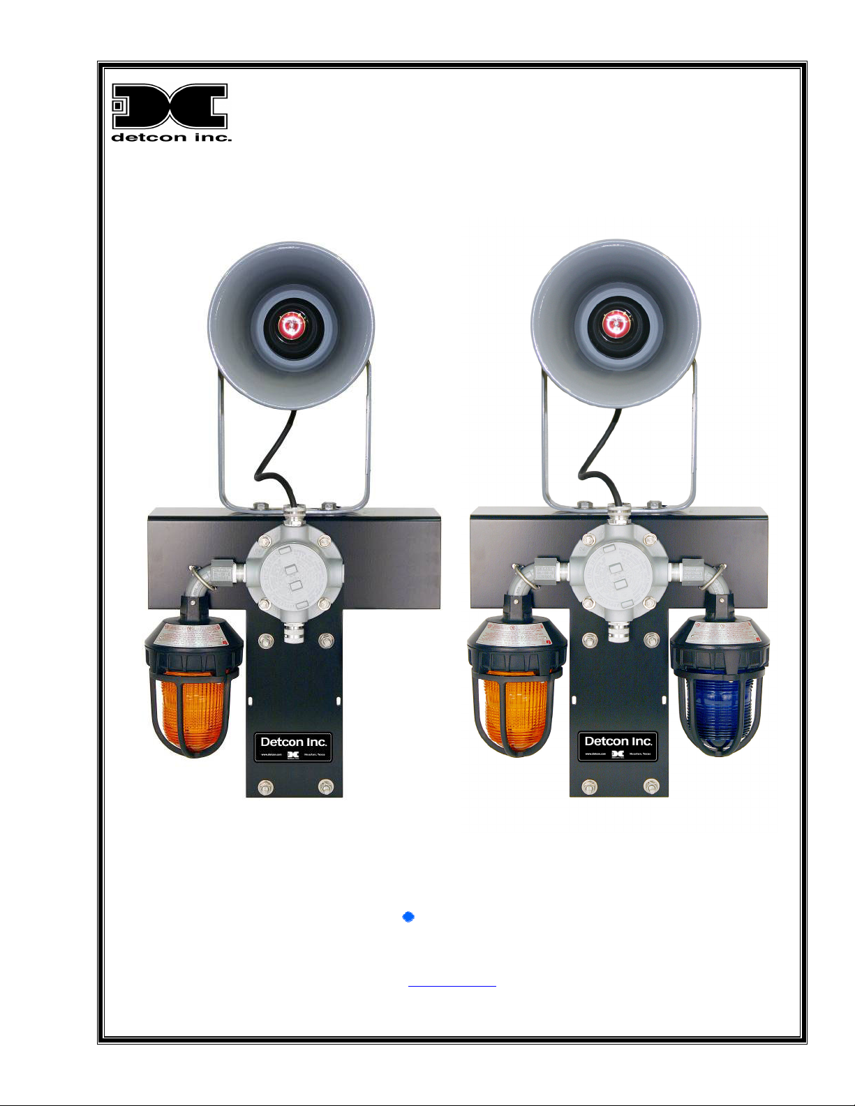
DETCON MODEL AV1/AV2-C1D2M
Hazardous Duty Class I. Div 2, Multitone Alarm Station
Operator’s Installation and Instruction Manual
The Woodlands, Texas 77387
Ph.281.367.4100 / Fax 281.298.2868
November 6, 2009 • Document #3080 • Revision 2.1
DETCON, Inc.
3200 Research Forest Dr,
www.detcon.com
Page 2

AV1/AV2-C1D2M
This page left intentionally blank
AV1/AV2-C1D2M Instruction Manual ii
Page 3

AV1/AV2-C1D2M
Table of Contents
Description................................................................................................................................................ 1
1.0
1.1 Strobe ................................................................................................................................................... 1
1.2 Siren ..................................................................................................................................................... 2
2.0 Installation................................................................................................................................................ 3
3.0 Parts List................................................................................................................................................... 7
4.0 Warranty .................................................................................................................................................. 7
5.0 Appendix................................................................................................................................................... 8
5.1 Revision Log ........................................................................................................................................ 8
Table of Figures
Figure 1 Strobe ..................................................................................................................................................... 1
Figure 2 SSTX-MV Siren..................................................................................................................................... 2
Figure 3 SSTX-MV printed circuit board ............................................................................................................ 3
Figure 4 AV1-C1D2M Dimensional.................................................................................................................... 4
Figure 5 AV2-C1D2M Dimensional.................................................................................................................... 5
Figure 6 120/240VAC wiring diagram ................................................................................................................ 6
Figure 7 24 VDC Wiring...................................................................................................................................... 6
AV1/AV2-C1D2M Instruction Manual iii
Page 4

AV1/AV2-C1D2M
This page left intentionally blank
This page left intentionally blank
Shipping Address: 3200 A-1 Research Forest Dr., The Woodlands Texas 77381
Mailing Address: P.O. Box 8067, The Woodlands Texas 77387-8067
Phone: 888.367.4286, 281.367.4100 • Fax: 281.292.2860 •
AV1/AV2-C1D2M Instruction Manual iv
www.detcon.com • sales@detcon.com
Page 5

AV1/AV2-C1D2M
1.0 Description
Detcon Model AV2-C1D2M audiovisual alarm stations are designed for installation and use in hazardous
duty, corrosive work environments. The Strobes are UL listed and CSA Certified for Class I, Division 2,
Groups A, B, C and D; Class II, Division I, Groups E, F, and G; and Class III. The siren is UL listed for Class
I, Groups B, C and D; Class II, Groups E, F, and G
light and a siren. The AV2-C1D2M alarm station consists of two strobe lights and a siren.
The station can be wired to control circuit alarm devices for the purpose of warning personnel of hazardous
conditions. When used in conjunction with Detcon controllers, the alarm station is typically used to provide a
low alarm (strobe) and high alarm (strobe/horn) for pre-determined hazardous environmental gas levels (toxic
or flammable) as indicated by remote mount sensors.
The alarm station strobe lights are configured with any combination of dome colors such as amber, blue, clear,
green, magenta, or red. Dome guards are included. The rugged warning light is specifically designed for
hazardous locations or corrosive environments where a very bright visual signal is required.
Hazardous location strobes are available in voltage ratings of 120VAC or 240VAC. The strobe light provides
80 high-intensity flashes per minute. UL listed and CSA certified for Class I, Division 2, Groups A, B, C and
D; Class II, Division I, Groups E, F, and G; and Class III.
The light meets Type 4X watertight, dust-tight, and corrosion resistant requirements; constructed to IP66. It
has an aluminum base coated for corrosion-resistance. The dome guard fits over the plastic dome to protect it
against accidental collision with moving equipment.
. The AV1-C1D2M alarm station consists of one strobe
1.1 Strobe
Figure 1 Strobe
Specification
Voltage 12-24VDC, 120VAC 50/60HZ, 240VAC 50/60HZ
Mount ¾” Pipe
Operating Current 0.60 Amps at 24VDC; 0.32 Amps at 120VAC, 0.16 Amps at 240VAC
Dome Colors Amber / Blue / Clear / Green / Magenta / Red
Dome Guard Included
Operating Temperature Minimum -31°F
AV1/AV2-C1D2M Instruction Manual Rev.2.1 Page 1 of 8
Page 6
AV1/AV2-C1D2M
Operating Temperature Maximum 150°F
Flash Rate/Minute 80
Effective Candle Power 165
Enclosure Rating Type 4X, IP66
Height 8.75in
Diameter 5.5in.
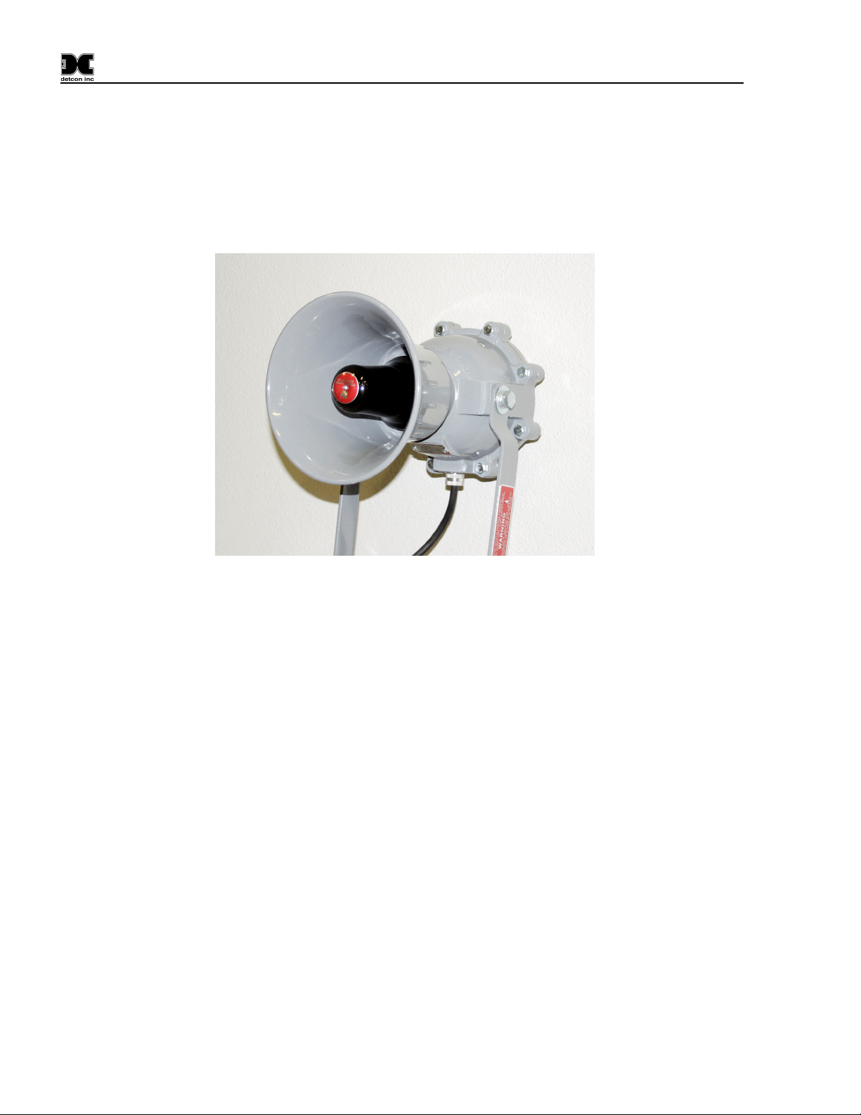
1.2 Siren
Figure 2 SSTX-MV Siren
The alarm station Explosion Proof Power Alarm® siren is a rain-tight solid-state audible alarm that features
four field selectable sounds: Wail, Yelp, Horn, and Temporal Slow Whoop.
The siren is weatherproof constructed with a cast aluminum housing and spun Aluminum horn. It produces a
noise level of a 98dbA @ 10 feet in a wide angle sound dispersion pattern.
The explosion proof power alarm siren is available in voltage ratings of 24VDC, 120VAC or 240VAC @
50/60Hz. and mounts on a unidirectional mounting bracket with ½” conduit access. UL listed for Class I,
Groups B, C and D
Specifications
Voltage 24VDC, 120 VAC 50/60 HZ, 240 VAC 50/60 HZ
Mount Omni Directional Mounting Bracket
Operating Current 0.6Amps at 24 VDC
0.21Amps at120 VAC
0.12Amps at 240 VAC
Temperature Rating -35°C to +72°C; -31°F to +161°F
Sound Output DB (A) @ 10’ on Axis
Wail
Yelp
Horn
108
108
102
Temporal Slow Whoop 102
Enclosure Rating Type3R, IP44
AV1/AV2-C1D2M Instruction Manual Rev. 2.1 Page 2 of 8
Page 7

AV1/AV2-C1D2M
Height 14.75in.
Width 8.88in.
Long 14.75in
Sound Selectable Positions Listed in Figure 3
Figure 3 SSTX-MV printed circuit board
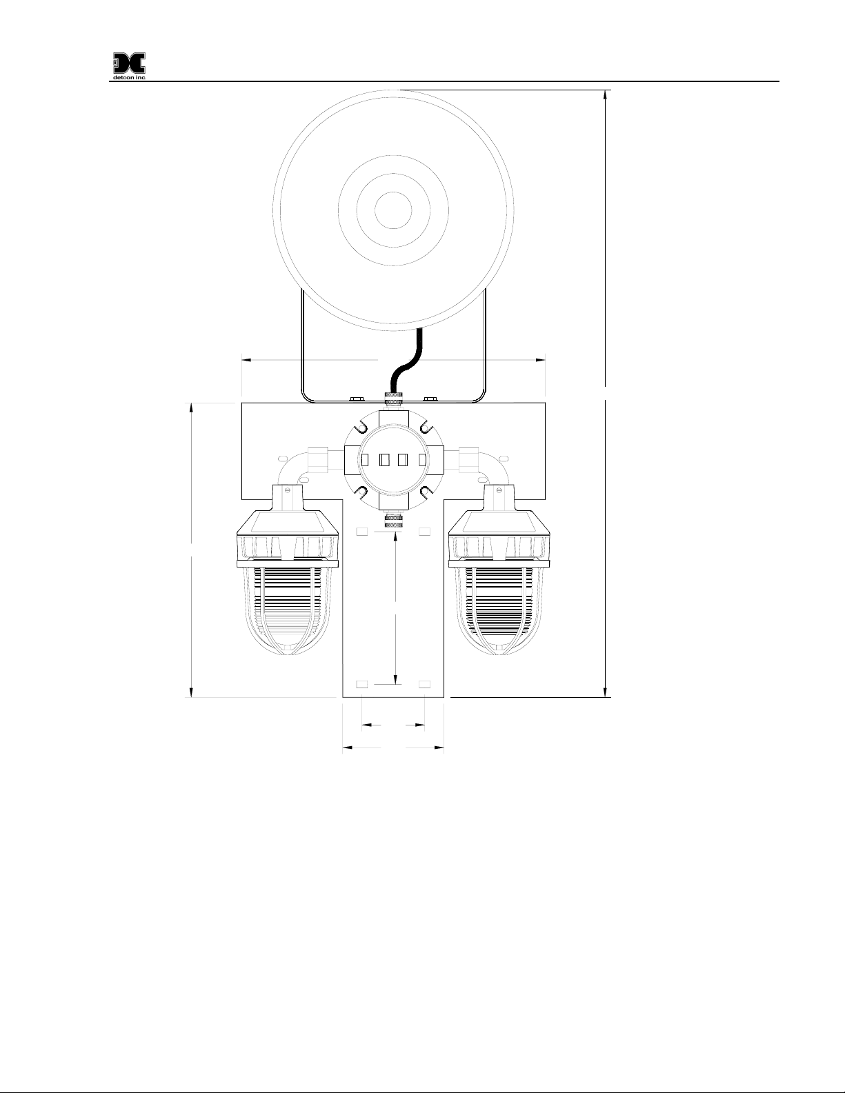
2.0 Installation
The assembly is mounted on a T-shaped Aluminum bracket with holes pre-drilled to accommodate (2) U-bolt
attachments on a 2.5” maximum diameter pipe. U-bolt size is 3/8-16 x 3 inches. Overall Dimensions are
33”H x 16.5”W x 18.5”D (Figure 4).
The tone for the siren is set using tone selector jumpers, J4 & J5. Each jumper consists of three pins and the
selection of appropriate tone is made by placing a jumper on two of the three pins as shown in .
The alarm comes pre-wired for the voltage ordered from the factory (110/220VAC or 24VDC). Wiring is
installed through the opening at bottom of junction box. Connect wiring in accordance with the appropriate
wiring diagram (Figure 6 or Figure 7), AV1-C1D2M being wired for Strobe 1 only. Use only 12 to 18 AWG
wire for power connections. Strip no more than 0.25-inch of insulation from the ends of the power leads.
AV1/AV2-C1D2M Instruction Manual Rev. 2.1 Page 3 of 8
Figure 3
Page 8

AV1/AV2-C1D2M
Ground can be connected either to the Condulet Ground Screw or to the Plug on the terminal board.
Optionally, each annunciator can be powered independently by removing the jumper between terminal points
5, 6, and 7, and wiring directly to the return path of the annunciator.
16"
16.5"
33"
8.3"
3.4"
5.5"
Figure 4 AV1-C1D2M Dimensional
AV1/AV2-C1D2M Instruction Manual Rev. 2.1 Page 4 of 8
Page 9
AV1/AV2-C1D2M
16.5"
33"
16"
8.3"
3.4"
5.5"
Figure 5 AV2-C1D2M Dimensional
AV1/AV2-C1D2M Instruction Manual Rev. 2.1 Page 5 of 8
Page 10

AV1/AV2-C1D2M
STROBE 1 STROBE 2
G
L1 L2
Blk
L1 Strobe 1
SIREN
L1 L1L2 L2
Wht
Wht
Blk
Blk
Wht
L1 Siren
L2 (Neu)
L1 Strobe 2
Wht
Grn/Ylw
Grn/Ylw
Grn/Ylw
GND
Customer Input Wiring
Figure 6 120/240VAC wiring diagram
GG
Standard wiring shown on
left.
Optional: Removal of jumper
between 5,6, and 7 for
discrete annunciator wiring
shown on right.
Ground can be connected to
the Ground Screw or the
connector.
Note: Strobe 2 not present
on AV!-C1D2C assembly
STROBE 1 STROBE 2
G
L1 L2
Blk
L1 Strobe 1
Customer Input Wiring
SIREN
L1 L1L2 L2
Wht
Wht
Blk
Blk
L1 Siren
L2 Strobe 1
L1 Strobe 2
Optional
L2 Strobe 2
Wht
L2 Siren
Grn/Ylw
Grn/Ylw
Grn/Ylw
GND
GG
STROBE 1 STROBE 2
G
L1 L2
Blk
L1 Strobe 1
SIREN
L1 L1L2 L2
Wht
Wht
Blk
Blk
Wht
L1 Siren
L2 (Neu)
L1 Strobe 2
Wht
Grn/Ylw
Grn/Ylw
Grn/Ylw
GND
Customer Input Wiring
GG
Standard wiring shown on
left.
Optional: Removal of jumper
between 5,6, and 7 for
discrete annunciator wiring
shown on right.
Ground can be connected to
the Ground Screw or the
connector.
Note: Strobe 2 not present
on AV!-C1D2C assembly
STROBE 1 STROBE 2
G
L1 L2
Blk
L1 Strobe 1
Customer Input Wiring
SIREN
L1 L1L2 L2
Wht
Wht
Blk
Blk
L1 Siren
L2 Strobe 1
L1 Strobe 2
Optional
L2 Strobe 2
Wht
L2 Siren
GG
Grn/Ylw
Grn/Ylw
Grn/Ylw
GND
Figure 7 24 VDC Wiring
AV1/AV2-C1D2M Instruction Manual Rev. 2.1 Page 6 of 8
Page 11

AV1/AV2-C1D2M
3.0 Parts List
Detcon Part # Description
500-003198-000 Alarm System Terminal Board
356-889321-MV0 24 VDC / 120VAC / 240VAC Hazardous Location Siren
354-1516X6-024 151XST – 24VDC Strobe, Ext Ground (X represents color of lamp)
354-1516X6-120 151XST – 120VAC Strobe, Ext Ground (X represents color of lamp)
354-1516X6-240 151XST – 240VAC Strobe, Ext Ground (X represents color of lamp)
Strobe colors: Red (2), Amber (4), Green (5), Blue (6), Magenta (7), and Clear (9)
4.0 Warranty
Detcon Inc., as manufacturer, warrants under intended normal use each new AV1/AV2-C1D2M Alarm station
to be free from defects in material and workmanship for a period of one year. The warranty period begins
from the date of shipment to the original purchaser and ends one year thereafter. All warranties and service
policies are FOB the Detcon Inc. facility located in The Woodlands, Texas.
AV1/AV2-C1D2M Instruction Manual Rev. 2.1 Page 7 of 8
Page 12

AV1/AV2-C1D2M
5.0 Appendix
5.1 Revision Log
Revision Date Changes made
1.2 March 6, 2006 Using Tomar WEP1002 siren
1.4 September 7, 2007 Changed to Federal Signal SSTX-MV siren, addition of spare parts for
the Siren
2.0 May 20, 2008 Modified wiring drawings to show common return and individual
activation of siren(s) and horn. Removed Federal Signal spare parts
2.1 November 6, 2009 Change to title of AV1/AV2-C1D2M, addition of picture and drawings
relating to AV1-C1D2M alarm station, addition of Revision log
Shipping Address: 3200 A-1 Research Forest Dr., The Woodlands Texas 77381
Mailing Address: P.O. Box 8067, The Woodlands Texas 77387-8067
AV1/AV2-C1D2M Instruction Manual Rev. 2.1 Page 8 of 8
Phone: 888.367.4286, 281.367.4100 • Fax: 281.292.2860 •
www.detcon.com • sales@detcon.com
 Loading...