

Page 1
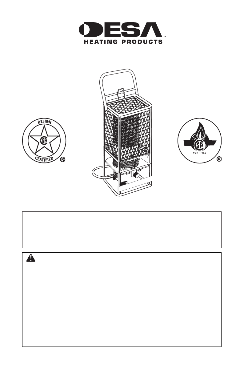
GAS-FIRED INFRARED CONSTRUCTION HEATER
OWNER’S MANUAL
MODELS 125-R AND 125-RN
IMPORTANT: Read and understand this manual before
assembling, starting or servicing heater. Improper use
of heater can cause serious injury. Keep this manual for
future reference.
GENERAL HAZARD WARNING:
Failure to comply with the precautions and instructions
provided with this heater, can result in death, serious
bodily injury and property loss or damage from hazards
of fire, explosion, burn, asphyxiation, carbon monoxide
poisoning and/or electrical shock.
Only persons who can understand and follow the instructions should use or service this heater.
If you need assistance or heater information such as an instructions manual, labels, etc. contact the manufacturer.
Save this manual for future reference.
For more information, visit www.desatech.com
Page 2
Safety Information ............................................... 2
TABLE OF CONTENTS
Product Identification ...........................................
Unpacking ........................................................... 3
Theory of Operation ............................................ 3
Gas Supply .......................................................... 4
Ventilation ............................................................
Installation Instructions ........................................ 4
Locating Heater ................................................... 5
Piping .................................................................. 5
Operating Instructions ......................................... 6
3
Maintenance ........................................................ 7
Specifications ...................................................... 7
Operating Instructions ......................................... 7
Troubleshooting ................................................... 8
4
Replacement Parts .............................................. 9
Accessories ......................................................... 9
Illustrated Parts Breakdown and Parts List ....... 10
Warranty and Repair Service ..............Back Cover
SAFETY INFORMATION
WARNING: This product
contains and/or generates
chemicals known to the State
of California to cause cancer or
birth defects or other reproduc
tive harm.
WARNING: Fire, burn, inhalation and explosion hazard.
Keep solid combustibles, such
as building materials, paper or
cardboard, a safe distance away
from the heater as recommended
by the instructions. Never use
the heater in spaces which do or
may contain volatile or airborne
combustibles or products such
as gasoline, solvents, paint thinner, dust particles or unknown
chemicals.
WARNING: Not for home or
recreational vehicle use.
WARNING: Do not exceed
1/2 psi (14" w.c.) gas pressure
to the gas control valve.
The heater is designed for use as a construction heater in accordance with ANSI Z83.7/CGA 2.14. Other
standards govern the use of fuel gases and heating
products for specific uses. Your local authority
can advise you about these. The primary purpose
of construction heaters is to provide temporary
heating of buildings under construction, alteration
or repair. Properly used, the heater provides safe
economical heating. Products of combustion are
vented into the area being heated.
-
We cannot foresee every use which may be made of
our heaters. Check with your local fire safety au
thority if you have questions about heater use.
Other standards govern the use of fuel gases and
heat producing products for specific uses. Your
local authorities can advise you about these.
Carbon Monoxide Poisoning: Some people are
more affected by carbon monoxide than others.
Early signs of carbon monoxide poisoning re
semble the flu, with headaches, dizziness and/or
nausea. If you have these signs, the heater may not
be working properly. Get fresh air at once! Check
for proper ventilation and have heater serviced.
Propane Gas: Propane gas is odorless. An odor-
making agent is added to propane gas. The odor
helps you detect a propane gas leak. However, the
odor added to propane gas may fade. Propane gas
may be present even though no odor exists.
Make certain you read and understand all warn
ings. Keep this manual for reference. It is your
guide to safe and proper operation of this heater.
1. Install and use heater with care. Follow all
local ordinances and codes. In the absence
of local ordinances and codes, refer to the
Standard for Storage and Handling of Liq
uefied Petroleum Gas, ANSI/NFPA 58 and
the Propane Installation Code, CAN/CGA
B149.2. This instructs on the safe storage and
handling of propane gases.
2. Use only the hose and factory preset regulator
provided with the heater.
3. Use only propane gas set up for vapor with
drawal (125-R only).
4. Provide adequate ventilation. Before using
heater, provide at least a .35 m
opening of fresh, outside air.
5. Do not use heater in occupied dwellings or in
living or sleeping quarters.
6. Do not use heater in basement or below ground
level.
2
(3.75 ft2)
-
-
-
-
-
2
www.desatech.com
114248-01B
Page 3

SAFETY INFORMATION
Continued
7. Keep appliance area clear and free from combustible materials, gasoline, paint thinner and
other flammable vapors and liquids. Dust is
combustible. Do not use heater in areas with
high dust content.
8.
Minimum heater clearances from combustibles:
Sides Top
1.54 m (5 ft) 1.22 m (4 ft)
9. Keep heater at least 6.0 m (20 ft) from propane
tank(s).
10. Keep propane tank(s) below 38° C (100° F).
11. Check heater for damage before each use. Do
not use a damaged heater.
12. Check hose before each use of heater. If highly
worn or cut, replace with hose specified by the
manufacturer before using heater.
13. Locate heater on stable and level surface if
heater is hot or operating.
14. Not intended for use on finished floors.
15. Never block air inlet (bottom of combustion
chamber) or air outlet (glowing combustion
chamber) of heater.
16. Keep heater away from strong drafts, wind,
water spray, rain or dripping water.
17. Do not leave heater unattended.
18. Keep children and animals away from
heater.
19. Never move, handle or service a hot or operat
ing heater. Severe burns may result. Wait 15
minutes after turning heater off.
20. To prevent injury, wear gloves when handling
heater.
21. Never attach duct work to heater.
22. Do not alter heater. Keep heater in its original
state.
23. Do not use heater if altered.
24.
Turn off gas supply to heater when not in use
25. Use only original replacement parts. This
heater must use design-specific parts. Do
not substitute or use generic parts. Improper
replacement parts could cause serious or fatal
injuries.
PRODUCT
IDENTIFICATION
Top
Protective
Screen
Combustion
Chamber
Cover
Lighting
Port
Control knob
Figure 1 - Product Identification
UNPACKING
1. Remove all packing items applied to heater for
shipment. Keep plastic cover caps (attached to
valve inlet and hose/regulator assembly) for
storage.
2. Remove all items from carton.
-
3. Check all items for shipping damage. If heater
is damaged, promptly inform dealer where you
bought heater.
THEORY OF OPERATION
The Fuel System: For propane units, the hose/
regulator assembly attaches to the propane gas
supply. For natural gas units, the gas supply at
taches to the heater through user supplied hose or
.
pipe. This provides fuel to the heater.
The Ignition System: The piezo ignitor lights the
burner fuel supply.
The Automatic Control System: This system causes
the heater to shut down if the flame goes out.
-
114248-01B
www.desatech.com
3
Page 4
GAS SUPPLY
PROPANE/LP GAS MODEL 125-R ONLY
Propane gas and propane tank(s) are to be furnished by the user.
Use this heater only with a propane vapor
withdrawal supply system. See Chapter 5 of the
Standard for Storage and Handling of Liquefied
Petroleum Gas, ANSI/NFPA 58 and/or CAN/CGA
B149.2. Your local library or fire department will
have this booklet.
The amount of propane gas ready for use from
propane tanks varies. Two factors decide this
amount.
1. The amount of liquid propane gas in tank(s)
2. The temperature of tank(s)
The chart below shows the minimum number of 45
kg (100 lb) tanks needed to run the heater. Connect
tanks together with a manifold.
Average Temperature Number Of Tanks
°C (°F) At Tank Location 45 kg (100 lb)
4° (40°) to 0° (32°) 2
Below 0° (32°) 3
Less gas is vaporized at lower temperatures. Your
local propane gas dealer will help you select the
proper supply system.
NATURAL GAS MODEL 125-RN ONLY
The user must furnish the natural gas supply and
the connections to the heater.
Regulate the natural gas supply down from a mini
mum 7" w.c. to a maximum of 1/2 psi. The natural
gas supply capacity should be able to supply a
minimum of 125 cubic feet of gas at pressure for
each heater connected to the system.
Consult your natural gas supplier for proper sizing
of the natural gas supply lines.
Follow all local ordinances and codes. In the ab
sence of local ordinances and codes, refer to the
National Fuel Gas Code Handbook, NFPA54/ANSI
Z223.1 and the Natural Gas Installation Code, CAN/
CGA B149.1
.
VENTILATION
WARNING: Provide at least
a .35 m2 (3.75 ft2) opening of
fresh, outside air while running
heater. If proper fresh, outside
air ventilation is not provided,
carbon monoxide poisoning
can occur. Provide proper fresh,
outside air ventilation before
running heater.
INSTALLATION
INSTRUCTIONS
Read these instructions carefully. Read and adhere to these
instructions. Do not allow anyone who has not read these
instructions to assemble, light,
adjust or operate this heater.
Do not attempt to operate the
heater with any gas other than
that indicated on the heater
nameplate.
For the U.S. and/or Canada, the installation of this
appliance must comply with local and/or Provin
cial codes or, in the absence of these codes, with
the (U.S.) National Fuel Gas Code, ANSI Z223.1
– Latest Edition (for natural and propane/LP gas
operation) and with the (U.S) Standard for the
Storage and Handling of Liquefied Petroleum
Gases, ANSI/NFPA 58 (for propane/LP gas opera
tion) or with the current (Canadian) CAN/CGA
B149.1 and B149.2 installation codes.
This heater (including hose and regulator assembly
if applicable) must be inspected before each use
and at least annually by a qualified service person.
If the hose for model 125-R shows evidence of
excessive abrasion or wear or if the hose is cut, it
must be replaced prior to the heater being put into
operation. The replacement hose assembly shall be
that specified by the manufacturer.
-
-
4
www.desatech.com
114248-01B
Page 5
LOCATING HEATER
The heater (and propane/LP gas supply cylinder
if applicable) must be located on a hard, flat, level
surface to minimize the risk of accidental tipping. If
an propane/LP gas supply cylinder is used (propane/
LP model only), the cylinder should be adequately
restrained to prevent accidental tipping. DO NOT
operate this heater with the supply cylinder in
any other than the upright position.
This appliance must be installed only in locations
where the potential for physical damage to the
appliance (i.e., due to physical contact) is reduced
to a minimum.
The installer must inform the owner/operator of
this appliance that precautions must be taken to
protect the appliance from physical damage.
This appliance produces radiant heat. Therefore,
it must be located at least 6 feet away from
any propane/LP gas container and must not be
directed toward any propane/LP gas container
within 20 feet.
The heater must be installed in a location such that
it will not be exposed directly to water spray, rain
and/or dripping water.
Use of this heater in a draft/windy area decreases
its efficiency. If possible, operate the unit in a
draft free area.
PIPING
FOR MODEL 125-R (FOR USE WITH
PROPANE/LP GAS ONLY)
This model may be connected to a self-contained
propane/LP gas supply system using the hose and
regulator assembly supplied with the appliance
OR, it may be connected to a permanently installed
propane/LP gas supply system.
If connected to a self-contained propane/LP
gas supply system, the hose assembly must be
inspected prior to each use of the heater. If it is
evident that there is excessive abrasion or wear or
if the hose is cut, it must be replaced prior to the
heater being put into operation.
WARNING: Never use a fork
lift truck type cylinder.
The connection of model 125-R to a propane/LP
cylinder must be made in a well ventilated area
using the regulator and hose assembly supplied
with the appliance. DO NOT attempt to adjust
this regulator. It has been preset at the factory
to provide safe and proper operation of the appliance. Use a 7/8" open end wrench to connect
the POL fitting (supplied with the propane/LP
regulator) to the propane/LP cylinder. Turn the
POL nut in a counterclockwise direction (left hand
thread) until tight. DO NOT use pipe compound
on POL threads.
The heater must be located at least six feet away
from any propane/LP cylinder and must not be
directed toward any propane/LP cylinder within
20 feet. If more than one heater is used, they
and the supply cylinders must be separated by at
least 20 feet.
The gas supply must be turned off at the propane/LP
supply cylinder when the heater is not in use.
When the heater is to be stored indoors, the connec
tion between the propane/LP supply cylinder and
the heater must be disconnected and the cylinder
removed from the heater and stored in accordance
with Chapter 5 of the Standard for the Storage and
Handling of Liquefied Petroleum Gases. ANSI/
NFPA 58 (U.S.) OR CAN/CGA B149.2 (Canada)
If connected to a permanently installed propane/LP
supply system, the system requires the use of a
two-stage gas regulator assembly which is nor
mally provided by your propane/LP dealer as part
of the propane/LP supply system. Consult with
your local propane/LP dealer for details concerning proper equipment and installation.
FOR MODEL 125-RN (FOR USE
WITH NATURAL GAS ONLY)
Piping must be clean and free from scale or burrs.
Install regulator supplied with heater. Connect with
1/2" NPT nipple to control valve.
Connect the appliance to an appropriately designed
and installed fuel supply system. This system must
include an approved manual shutoff valve which
is readily accessible and is located within 6 feet
of the appliance. Additionally, a sediment trap or
drip leg must be located upstream of this manual
shutoff valve. Refer to the appropriate (natural gas)
installation code noted above. If a flexible connec
tor is used, it must be of an approved type.
WARNING: Never use a flame
for gas leak testing.
-
.
-
-
114248-01B
www.desatech.com
5
Page 6
OPERATING
INSTRUCTIONS
WARNING: If you do not follow these instructions exactly,
a fire or explosion may result
causing property damage, personal injury or loss of life.
CAUTION: This appliance
is hot during normal operation,
avoid physical contact.
CAUTION: Do not place
clothing or other combustible
materials on this appliance.
DO NOT operate this heater if any part has been
under water. Call a qualified service technician to
inspect the appliance and to replace any part of
the control system or gas control valve which has
been under water.
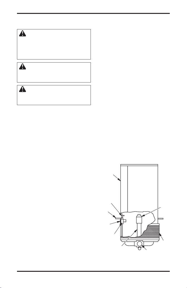
LIGHTING HEATER
1. Before attempting to light the heater, smell
all around the heater area for gas. Turn on
the gas supply to the appliance and check all
fittings and connections for gas leaks using a
mild soap and water solution. NEVER use a
match to check for gas leaks. Should a gas leak
occur, shut off the gas supply to the appliance
immediately. Wait a minimum of five minutes
before repairing the leak.
2. Use only the fuel intended for this appliance.
Check the appliance rating plate for the correct
fuel information.
3. Turn the control knob clockwise to the OFF
position. See Figure 1, page 3 and Figure 2
for location of appliance parts.
4. Wait a sufficient length of time (at least five
minutes) to allow gas which may have ac
cumulated in burner compartment to escape.
5. Turn on the main gas supply.
6. Turn control knob counterclockwise to the
PILOT position.
7a.
Press and turn control knob counterclockwise to
PILOT position and hold for 1 to 2 minutes. This
may take longer to purge air from supply hose
depending on length of the hose being used.
Press red spark ignition button to light pilot
flame (repeat until pilot lights) and continue to
hold control knob at PILOT position for 30-60
seconds to enable pilot light safety system. Fully
turn control knob to HI position to light burner.
7b. To match light the pilot, move the lighting
hole cover aside (see Figure 2) and place a
lighted match into hole. Press control knob
and hold while lighting and observing pilot
burner. Ensure that pilot burner ignites from
match. Allow pilot to burn approximately 30
seconds before releasing control knob. If pilot
does not remain lit, repeat lighting operation
allowing a longer period of time before releasing control knob.
Note: In cases where long runs of gas supply lines
have been installed ahead of the appliance, it may
be necessary to bleed trapped air out of supply lines
before lighting pilot. New installations generally
require bleed of supply lines. Wait a minimum of
five minutes after bleeding supply lines before
attempting to light heater.
Adjust pilot if necessary as noted under Pilot
Burner Adjustment
8. Turn control knob counterclockwise to the ON
position. The burner will light. DO NOT oper
ate heater in any position other than full ON.
IMPORTANT: DO NOT attempt to adjust the
main burner input using the main gas supply valve.
This may cause the pilot and thermocouple to shut
down the burner.
Combustion
Chamber
Thermocouple
Mounting
Brace
-
Match
Lighting
Hole Cover
Pilot Assembly
Gas Manifold
Figure 2 - Appliance Parts Identification
, page 7.
Control knob
-
Burner
Filter
6
www.desatech.com
114248-01B
Page 7
OPERATING
INSTRUCTIONS
Continued
SHUTTING OFF HEATER
• For short periods of time, turn the main burner
off by turning control knob clockwise to the
PILOT position.
• For extended periods of non use, turn appli
ance completely off by turning control knob
clockwise to the PILOT position, press knob
slightly, then turn knob fully clockwise to
the OFF position.
models, also turn off gas supply cylinder.)
Note: For propane/LP gas
PILOT BURNER ADJUSTMENT
1. Remove pilot adjustment cap. The pilot adjust-
ment cap is a slotted screw located in front
of the PILOT designation stamped on top of
valve body just below control knob.
2. Adjust pilot key to provide properly sized
flame. Rotate the key clockwise to decrease
flame or counterclockwise to increase flame.
3. Replace pilot adjustment cap.
MAINTENANCE
WARNING:
• Never attempt to service
heater while it is connected to
propane supply, operating or
hot. Severe burns can occur.
• Keep heater clear and free
from combustible materials,
gasoline and other flammable
vapors and liquids.
• Do not block the flow of combustion or ventilation air.
1. Keep heater clean. Clean heater annually or as
needed to remove dust and debris. If heater is
dirty or dusty, clean heater with a damp cloth.
Use household cleaners on difficult spots.
2. Inspect heater before each use. Check connec
tions for leaks. Apply mixture of liquid soap
and water to connections. Bubbles forming
show a leak. Correct all leaks at once.
3. Inspect hose/regulator assembly before each
use. If hose is highly worn or cut, replace.
4. Have heater inspected yearly by a qualified
service agency.
SPECIFICATIONS
Propane/LP Model 125-R
Rating
Fuel Propane Vapor Only
Fuel Consumption per Hour
5.17 liters (1.3 gallon)
2.6 kg (5.8 pounds)
Supply Pressure To Regulator (for input adjustment)
Maximum 1380 kPa (200 psi)
Minimum 138 kPa (20 psi)
Manifold Pressure 2.3 kPa (9.5 inches W.C.)
Weight
Heater 17.69 kg (39 lbs)
Shipping 20.86 kg (46 lbs)
Size - L x W x H 40.6 x 45.7 x 109.2 cm
(16 x 18 x 43 inches)
Min Temperature -29 °C (-20° F) Surrounding
Air Temperature
Natural Gas Model 125-RN
Rating
Fuel Natural Gas Only
Fuel Consumption
per Hour 3.5 m
Manifold Pressure 1.5 kPa (6 inches W.C.)
Weight
Heater 17.69 kg (39 lbs)
Shipping 20.86 kg (46 lbs)
Size - L x W x H 40.6 x 45.7 x 109.2 cm
(16 x 18 x 43 inches)
Min Temperature -29 °C (-20° F) Surrounding
Air Temperature
-
125,000 Btu/Hr (131,882 kj)
125,000 Btu/Hr (131,882 kj)
3
(125 ft3)
114248-01B
www.desatech.com
7
Page 8
TROUBLESHOOTING
WARNING: Never attempt to service heater while it is connected
to propane supply, operating or hot. Severe burns can occur.
SYMPTOM
Burner fails to light
Pilot lights but goes out when
automatic control valve button
is released
Burn rate is low
POSSIBLE CAUSE
1. Gas supply valve closed
2. Exce ss-flo w ch eck valve
closed (p ropane/LP units
only)
3. Blockage in burner orifice
4. Piezo ignition system not
sparking
1. Not enough warm-up time
2. Low gas pressure
3. Thermocouple loose or needs
to be replaced
4. Automatic control valve needs
to be replaced
1. Main burner valve not fully
open
2. Plugged gas orifices
3. Low gas pressure
4. Low fuel supply
REMEDY
1. Open gas supply valve slowly
2. Close propane supply valve
on propane tank and reopen
slowly
3. Replace burner orifice
4. Assure ignitor electrode gap is
5.0 mm (.195 in). Check wire
lead for damage Replace piezo
ignitor and/or ignitor electrode
as necessary. Do not bend elec
trode, this may cause breakage
1. Relight, hold automatic control
valve button in 45 seconds
2. Check for proper gas supply
3. Tighten connection or replace
thermocouple
4. Replace automatic control
valve
1. Fully open main burner valve
by pushing in control knob
and turning counterclockwise
towards HIGH position until
it stops
2. Replace gas orifice
3. Check gas supply; check
regulator output
4. Consult gas supplier to determine adequate supply. If using
propane/LP gas, the tank could
be empty
-
8
www.desatech.com
114248-01B
Page 9

REPLACEMENT PARTS
WARNING: Use only original
replacement parts. This heater
must use design-specific parts.
Do not substitute or use generic
parts. Improper replacement
parts could cause serious or fatal injuries. This will also protect
your warranty coverage for parts
replaced under warranty.
PARTS UNDER WARRANTY
Contact authorized dealers of this product. If they
canʼt supply original replacement part(s), either call
DESA Heating Productsʼ at 1-866-672-6040 or
DESA Industries at 1-905-826-8010.
When calling DESA, have ready:
• your name and address
• model and serial numbers of your heater
• how heater was malfunctioning
• purchase date
In most cases, we will ask you to return the part
to the factory.
PARTS NOT UNDER WARRANTY
Contact authorized dealers of this product. If they
canʼt supply original replacement part(s), call DESA
Heating Productsʼ at 1-866-672-6040 or DESA
Industries at 1-905-826-8010..
When calling DESA, have ready:
• model and serial numbers of your heater
• the replacement part number
ACCESSORIES
Purchase accessories and parts from your nearest
dealer or service center. If your dealer or service
center can not supply an accessory or part, call
DESA Heating Products at 1-866-672-6040 or
DESA Industriesʼ at 1-905-826-8010. You can
also write to the addresses listed on the back page
of this manual.
FUEL GAS CONNECTOR - LPA4020
Connects regulator to all standard propane tanks.
U.L. and AGA listed.
114248-01B
www.desatech.com
9
Page 10

ILLUSTRATED PARTS BREAKDOWN
20
14
22
9
23
8
19
16
18
1
17
6
7
24
4
11
5
3
21
15
12
13
10
2
MODELS 125-R AND 125-RN
10
www.desatech.com
114248-01B
Page 11

PARTS LIST
This list contains replaceable parts used in your heater. When ordering parts, follow the instructions
listed under Replacement Parts on page 9 of this manual.
KEY PART NUMBER
NO. 125-R 125-RN DESCRIPTION QTY.
1 104119-01 104119-01 Manual Control Valve 1
2 114049-01 114049-01 Filter/Diffuser 1
3 114120-01 114148-01 Pilot Orifice 1
4 114121-01 114121-01 Thermocouple 1
5 114128-01 114128-01 Pilot Burner 1
6 114134-01
_____
7
8 114244-01 114244-01 Pilot Supply Tube 1
9 114153-01 114153-01 Ignitor 1
10 102445-01 102445-01 Piezo 1
11 114243-01 114243-01 Spacer 1
12 114154-01 114154-01 Axle 1
13 114156-01 114156-01 Axle Brackets 1
14 114157-01 114157-01 Handle 1
15 114208-01 114208-01 Wheel 2
16 114209-01 114209-01 Valve Supply Tube Clamp 1
17 114212-01 114212-01 Valve Supply Tube 1
18 114213-01 114213-01 Burner Manifold 1
19 114216-01 114216-01 Burner 1
20 ** ** Frame Assembly 1
21 ** ** Combustion Chamber 1
22 ** ** Top Plate 1
23 114241-01 114241-01 Burner Mounting Plate 1
24 114242-01 114242-01 Pilot Mounting Bracket 1
114245-01 114245-02 General Info Decal 1
114246-01 114246-01 Caution Decal 1
113985-02 113985-03 Tradename Decal 1
115297-01 115297-01 Hang Tag 1
** Not a field replaceable part
_____
Hose/Regulator Assembly 1
103406-03 Regulator 1
PARTS AVAILABLE - NOT SHOWN
114248-01B 11
www.desatech.com
Page 12

WARRANTY AND REPAIR SERVICE
KEEP THIS WARRANTY
Model
Serial No.
Date of Purchase
LIMITED WARRANTY
DESA warrants this product and any parts thereof, to be free from defects in materials and workmanship for
one (1) year from the date of first purchase when operated and maintained in accordance with instructions. This
warranty is extended only to the original retail purchaser, when proof of purchase is provided.
This warranty covers only the cost of parts and labor required to restore the product to proper operating condition.
Transportation and incidental costs associated with warranty repairs are not reimbursable under this warranty.
Warranty service is available only through authorized dealers and service centers.
This warranty does not cover defects resulting from misuse, abuse, negligence, accidents, lack of proper main
tenance, normal wear, alteration, modification, tampering, contaminated fuels, repair using improper parts or
repair by anyone other than an authorized dealer or service center. Routine maintenance is the responsibility
of the owner.
THIS EXPRESS WARRANTY IS GIVEN IN LIEU OF ANY OTHER WARRANTY EITHER EXPRESSED
OR IMPLIED, INCLUDING WARRANTIES OF MERCHANTABILITY AND FITNESS FOR A PARTICU
LAR PURPOSE.
DESA assumes no responsibility for indirect, incidental or consequential damages. Some states do not allow
the exclusion or limitation of incidental or consequential damages or limitations or exclusions may not apply
to you. This Limited Warranty gives you specific legal rights and you may also have other rights which vary
from state to state.
We reserve the right to amend these specifications at any time without notice. The only warranty applicable is our
standard written warranty. We make no other warranty, expressed or implied.
WARRANTY SERVICE
Should your heater require service, return it to your nearest authorized service center. Proof of purchase must be
presented with the heater. The heater will be inspected. A defect may be caused by faulty materials or workmanship.
If so, DESA will repair or replace the heater without charge.
REPAIR SERVICE
Return your heater to your nearest authorized service center. Repairs not covered by the warranty will be billed at
standard prices. Each Service Center is independently owned and operated. We reserve the right to amend these
specifications at any time without notice.
When writing for information regarding your heater, be sure to include the model number and serial number as shown
on the model plate.
For more information about this warranty, write:
-
-
2701 Industrial Drive
P.O. Box 90004
Bowling Green, KY 42102-9004
ATTN: Customer Service Department
2220 Argentia Road, Unit #4
Mississauga, Ontario
L5N2K7
Page 13

APPAREIL DE CHAUFFAGE DE CHANTIER AU GAZ À
INFRAROUGE
MANUEL D’UTILISATION
MODÈLES 125-R ET 125-RN
IMPORTANT : Lisez et comprenez ce manuel avant d’assembler,
d’allumer ou de réparer l’appareil de chauffage. Une mauvaise
utilisation de l’appareil de chauffage peut causer des blessures
graves. Conservez ce manuel pour référence future.
AVERTISSEMENT DE RISQUE GÉNÉRAL :
Tout manquement aux précautions et aux instructions four
nies avec cet appareil de chauffage peut causer la mort, des
blessures corporelles graves ainsi que des pertes matérielles
et des dommages causés par les risques associés au feu, à
une explosion, aux brûlures, à l’asphyxie, à l’empoisonne
ment au monoxyde de carbone et par les chocs électriques.
Seuls les individus qui comprennent et suivent les instruc
tions peuvent utiliser ou réparer cet appareil de chauffage.
Si vous avez besoin d’assistance ou de renseignements con
cernant l’appareil de chauffage tels que le mode d’emploi, les
étiquettes, etc., communiquez avec le fabricant.
Conservez ce mode d’emploi pour consultation future.
Pour plus de détails, visitez le site www.desatech.com
-
-
-
-
Page 14

TABLE DES MATIÈRES
Information relative à la sécurité ......................... 2
Identification du produit ....................................... 3
Déballage ............................................................ 3
Théorie de fonctionnement .................................. 3
Alimentation en gaz ............................................. 4
Ventilation ............................................................ 4
Instructions pour l’installation .............................. 4
Placement de l’appareil de chauffage ................. 5
Tuyauterie ............................................................
Notice d’utilisation ............................................... 6
Entretien .............................................................. 7
Spécifications ...................................................... 7
Notice d’utilisation ............................................... 7
Dépannage .......................................................... 8
Pièces de rechange ............................................. 9
Accessoires ......................................................... 9
Vue détaillée et liste des pièces ........................ 10
5
Service de garantie et de réparation ..Couverture arrière
INFORMATION RELATIVE
À LA SÉCURITÉ
AVERTISSEMENT : cet appareil
contient ou produit des produits
chimiques déterminés par l’État de
Californie comme cancérigènes et
pouvant causer des malformations
congénitales et d’autres problèmes
liés à la reproduction.
AVERTISSEMENT : danger d’incendie, de brûlure, d’inhalation et
d’explosion. Garder les produits com
bustibles solides comme les matériaux
de construction, le papier et les cartons,
à une distance sûre de l’appareil de
chauffage tel que recommandé dans
les instructions. Ne jamais utiliser l’ap
pareil de chauffage dans des espaces
susceptibles de contenir des com
bustibles volatils ou atmosphériques
ou des produits tels que de l’essence,
des diluants, du solvant à peinture,
des particules de poussières ou des
produits chimiques inconnus.
AVERTISSEMENT : cet appareil
n’est pas conçu pour usage domestique
ou dans les véhicules de camping.
AVERTISSEMENT : la pression
ne doit pas dépasser 34 hPa (0,5
lb/po3 ou 14 po CE) à la vanne de
contrôle de gaz.
Cet appareil de chauffage est conçu comme appareil de
chauffage de chantier en conformité avec les normes
ANSI Z83.7/CGA2.2.14. Dʼautres normes régissent
lʼutilisation des gaz combustibles et des produits
de chauffage pour des utilisations particulières. Les
2
-
-
-
www.desatech.com
autorités locales peuvent vous conseiller à propos de
ces normes. La fonction principale des appareils de
chauffage de chantier est la production temporaire de
chaleur pour des édifices en construction ou en cours
de modification ou de réparation. Utilisés correctement,
ces appareils de chauffage représentent une source de
chaleur économique et sûre. Les produits de combustion sont évacués dans lʼespace qui est chauffé.
Nous ne pouvons pas prévoir toutes les utilisations
possibles de nos appareils de chauffage. Vérifiez
auprès de votre responsable local de la sécurité-incendie si vous avez des questions relatives à
lʼutilisation de lʼappareil de chauffage.
Dʼautres normes régissent lʼutilisation des gaz combustibles et des produits de chauffage pour des utilisations particulières. Les autorités locales peuvent
vous conseiller à propos de ces normes.
Empoisonnement au monoxyde de carbone : certaines
personnes sont plus sensibles au monoxyde de carbone
que dʼautres. Les premiers symptômes dʼun empoisonnement au monoxyde de carbone ressemblent à la grippe
avec des maux de tête, du vertige ou de la nausée. Si
vous avez ces symptômes, il se pourrait que lʼappareil de
chauffage ne fonctionne pas bien. Respirez tout de suite
de lʼair frais ! Vérifiez si la ventilation est suffisante et
faites réparer lʼappareil de chauffage.
Gaz propane : le gaz propane nʼa pas dʼodeur. Un pro-
duit odorant est ajouté au gaz propane. Cette odeur vous
permet de détecter une fuite de propane. Cependant,
cette odeur ajoutée au propane peut se dissiper. Du gaz
propane peut être présent même sʼil nʼy a pas dʼodeur.
Lisez et comprenez tous les avertissements. Conservez ce manuel pour consultation future. Il vous permettra de faire fonctionner cet appareil de chauffage
correctement et en toute sécurité.
1.
Installez et utilisez lʼappareil de chauffage avec précaution. Suivez toutes les lois et les codes locaux. En
lʼabsence de codes ou de règlements locaux, consultez
la Norme pour lʼemmagasinage et la manipulation
du gaz de pétrole liquéfié (ANSI/NFPA 58) et le Code
dʼinstallation du gaz propane (CAN/CGA B149.2). Ces
documents décrivent les précautions à prendre pour
lʼentreposage et la manutention du gaz propane.
2. Nʼutilisez que le tuyau et le détendeur réglé en usine
qui ont été fournis avec lʼappareil de chauffage.
3. Nʼutilisez que du gaz propane composé pour
le retrait de vapeur (modèle 125-R).
114248-01B
Page 15

INFORMATION RELATIVE À
LA SÉCURITÉ
4. Assurez une ventilation suffisante. Avant dʼutiliser
le radiateur, aménagez une prise dʼair frais de
lʼextérieur dʼau moins 0,35 m2 (3,75 pi2).
5. Nʼutilisez pas lʼappareil de chauffage dans un édifice
habité ou dans des endroits où lʼon vit et dort.
6. Nʼutilisez pas lʼappareil de chauffage dans les
sous-sols ou sous le niveau du sol.
7. Dégagez lʼemplacement du radiateur et gardez-le
libre de matériaux combustibles, dʼessence, de
solvant à peinture ou dʼautres vapeurs et liquides
inflammables. La poussière est combustible.
Nʼutilisez pas lʼappareil de chauffage là où il y a
beaucoup de poussière.
8. Distances minimales entre lʼappareil de chauffage
et les produits combustibles :
Côtés Dessus
1,52 m (5 pi) 1,22 m (4 pi)
9. Placez lʼappareil de chauffage à au moins 6,1 m
(20 pi) des réservoirs de propane.
10.
Conservez les réservoirs de propane à moins de
38 °C (100 °F).
11. Vérifiez lʼappareil de chauffage avant chaque
utilisation. Nʼutilisez pas dʼappareil de chauffage
endommagé.
12. Avant chaque utilisation de lʼappareil de chauffage,
vérifiez si le tuyau nʼest pas endommagé. Sʼil est très
usé ou fendu, remplacez-le par un tuyau spécifié par
le fabricant avant dʼutiliser lʼappareil de chauffage.
13. Placez lʼappareil de chauffage sur une surface
stable et de niveau si lʼappareil est chaud ou en
fonctionnement.
14. Cet appareil nʼest pas conçu pour utilisation sur des
planchers finis.
15. Ne jamais obstruer lʼentrée dʼair (au bas de la
chambre de combustion) ou la sortie dʼair (chambre
de combustion radiante) du radiateur.
16. Éloignez lʼappareil de chauffage des courants dʼair,
du vent, des éclaboussures, de la pluie ou de lʼeau
ruisselante.
17. Ne laissez pas lʼappareil de chauffage sans sur
veillance.
18. Ne laissez pas les enfants et les animaux sʼappro
cher de lʼappareil de chauffage.
19. Ne déplacez, ne manipulez et ne révisez jamais un
appareil de chauffage brûlant ou en opération. Vous
risqueriez de vous brûler gravement. Attendez 15
minutes après avoir éteint lʼappareil de chauffage.
20. Pour ne pas vous blesser, portez des gants lorsque
vous manipulez lʼappareil de chauffage.
21. Ne raccordez jamais de tuyauterie de ventilation à
lʼappareil de chauffage.
22. Ne modifiez pas lʼappareil de chauffage. Maintenez
lʼappareil de chauffage dans son état initial.
114248-01B
Suite
www.desatech.com
23.
Nʼutilisez pas lʼappareil de chauffage sʼil a été
modifié.
24. Fermez lʼalimentation en propane de lʼappareil de
chauffage sʼil nʼest pas utilisé.
25. Utilisez seulement des pièces de rechange dʼori
gine. Cet appareil de chauffage utilise des pièces
conçues spécifiquement pour lui. Nʼutilisez pas de
substituts ou de pièces génériques. Lʼutilisation de
pièces de rechange inappropriées peut causer des
blessures graves ou fatales.
IDENTIFICATION DU
PRODUIT
Dessus
Écran de
protection
Chambre de
combustion
Orifice
d’allumage du
couvercle
Bouton de réglage
Figure 1 - Identification du produit
DÉBALLAGE
1. Enlevez le matériau dʼemballage appliqué sur
lʼappareil de chauffage pour son expédition.
Conservez les bouchons en plastique (fixés à
lʼentrée de la vanne et à lʼassemblage du tuyau
et du détendeur) pour lʼentreposage.
2. Retirez toutes les pièces de lʼemballage.
3. Inspectez toutes les pièces pour voir si elles ont
été endommagées pendant le transport. Si lʼappa-
reil de chauffage est endommagé, informez-en au
plus vite le revendeur où vous lʼavez acheté.
-
THÉORIE DE FONCTIONNEMENT
Système d’alimentation en carburant : lʼassemblage
du tuyau et du détendeur est relié à lʼalimentation en
gaz propane. Dans le cas des appareils au gaz naturel,
lʼalimentation en carburant est connectée au radiateur
avec un tuyau ou un tube fournis par lʼutilisateur. Il
achemine le combustible à lʼappareil de chauffage.
Circuit d’allumage : lʼallumeur piézo-électrique allume
lʼalimentation du brûleur.
Système de contrôle automatique : ce système provo-
que lʼarrêt de lʼappareil de chauffage en cas dʼextinction
de la flamme.
-
3
Page 16

ALIMENTATION EN GAZ
MODÈLE 125-R AU GAZ PROPANE
ET GPL SEULEMENT
Le gaz propane et les réservoirs de propane doivent
être fournis par lʼutilisateur.
Nʼutilisez cet appareil de chauffage quʼavec un
système dʼapprovisionnement à retrait de vapeur
de propane. Consultez le chapitre 5 de la
pour lʼemmagasinage et la manipulation du gaz
de pétrole liquéfié, ANSI/NFPA 58 et/ou CAN/CGA
B149.2. Votre bibliothèque ou votre service dʼin-
cendie ont cette publication.
La quantité de gaz propane utilisable dans les réservoirs
varie. Deux facteurs influencent cette quantité :
1. La quantité de gaz propane contenue dans les
réservoirs
2. La température des réservoirs
Le tableau ci-dessous indique le nombre minimum
de réservoirs de 45 kg (100 lb) à utiliser pour faire
fonctionner lʼappareil de chauffage. Raccordez les
réservoirs entre eux avec un collecteur.
Température moyenne
°C (°F) à l’emplacement Nombre de réservoirs
des réservoirs 45 kg (100 lb)
4° (40°) à 0° (32°) 2
Sous 0° (32°) 3
Moins de gaz se vaporise à basse température.
Votre fournisseur de gaz propane local vous aidera
à choisir le système dʼalimentation qui convient.
MODÈLE 125-RN AU GAZ NATUREL
SEULEMENT
Lʼutilisateur doit fournir lʼalimentation en gaz et
les raccordements au radiateur.
Régulez lʼalimentation en gaz entre un minimum
de 17 hPa (7 po CE) et un maximum de 34 hPa (0,5
lb/po). La capacité de lʼalimentation en gaz naturel
devrait pouvoir fournir au moins 3,54 m
de gaz à la pression recommandée à chacun des
radiateurs connectés au système.
Consultez votre fournisseur local de gaz naturel au
sujet des dimensions appropriées des canalisations
de gaz naturel.
Suivez toutes les lois et les codes locaux. En
lʼabsence de codes ou de règlements locaux,
reportez-vous au Guide national du gaz naturel
(NFPA54/ANSI Z223.1) et au Code dʼinstallation
du gaz naturel (CAN/CGA B149.1)
.
Norme
3
(125 pi3)
VENTILATION
AVERTISSEMENT : il doit y
avoir une ouverture sur l’air extérieur d’au moins 0,35 m
2
(3,75 pi2)
pendant le fonctionnement du radiateur. Si aucune ventilation d’air
frais de l’extérieur n’est fournie, un
empoisonnement au monoxyde
de carbone peut se produire.
Prévoyez une entrée d’air frais de
l’extérieur suffisante avant d’utili
-
ser l’appareil de chauffage.
INSTRUCTIONS POUR
L’INSTALLATION
Lisez attentivement ces instructions. Conformez-vous à
ces instructions. Ne laissez
personne assembler, allumer,
régler ou faire fonctionner ce
radiateur si cette personne n’a
pas lu ces instructions.
N’essayez pas de faire fonctionner cet appareil de chauffage
avec tout autre gaz que celui
spécifié sur la plaque signalétique de l’appareil.
Aux États-Unis et au Canada, lʼinstallation de cet
appareil doit se conformer aux codes locaux et
provinciaux ou, en leur absence, au Code national
du gaz naturel (États-Unis) ANSI Z223.1 - dernière
édition (pour le fonctionnement au gaz propane,
au GPL et au gaz naturel), à la Norme pour lʼem-
magasinage et la manipulation du gaz de pétrole
liquéfié ANSI/NFPA 58 (pour le fonctionnement au
gaz propane ou au GPL) ou avec les codes dʼinstallation canadiens mis à jour (Canada) CAN/CGA
B149.1 et B149.2.
Cet appareil de chauffage (incluant lʼensemble
tuyau et détendeur, sʼil y a lieu) doit être examiné
avant chaque utilisation et au moins une fois lʼan
par un technicien qualifié. Si le tuyau du modèle
125-R montre des signes dʼabrasion excessive ou
dʼusure, ou sʼil est fendu, il doit être remplacé
avant de mettre le radiateur en marche. Le rem
placement doit être conforme aux spécifications
du fabricant.
-
4
www.desatech.com
114248-01B
Page 17

PLACEMENT DE
L’APPAREIL DE CHAUFFAGE
Lʼappareil de chauffage (et le réservoir de gaz
propane ou de GPL sʼil y a lieu) doit être placé sur
une surface solide, plane et de niveau pour mini
miser les risques de renversement. Si un réservoir
dʼalimentation en gaz propane ou en GPL est utilisé,
le réservoir doit être solidement arrimé pour préve
nir un renversement accidentel. NʼUTILISEZ PAS
cet appareil de chauffage avec un réservoir qui
nʼest pas en position verticale.
Cet appareil ne doit être placé quʼà un endroit où le
potentiel de dommage matériel au radiateur (dû à
un contact physique, par exemple) est minimal.
Lʼinstallateur doit informer le propriétaire ou lʼutilisateur que des précautions doivent être prises pour
protéger lʼappareil contre les dommages matériels.
Cet appareil produit une chaleur radiante. Par
conséquent, il doit être placé à au moins 1,83 m
(6 pi) de tout réservoir de gaz propane ou de GPL
et ne doit pas être dirigé vers un tel réservoir situé
à moins de 6,1 m (20 pi).
Lʼappareil de chauffage doit être placé dans un
endroit à lʼabri des éclaboussures, de la pluie et
de lʼeau ruisselante.
Lʼutilisation de ce radiateur dans un endroit
venteux ou avec des courants dʼair réduit son
rendement. Si possible, utilisez cet appareil dans
un endroit sans courants dʼair.
TUYAUTERIE
POUR LE MODÈLE 125-R
(UTILISATION AVEC GAZ PROPANE
OU GPL SEULEMENT)
Ce modèle peut être connecté à un système autonome dʼalimentation en gaz propane ou en GPL
en utilisant lʼassemblage de tuyau et de détendeur
fourni avec lʼappareil OU à une installation perma
nente dʼalimentation en gaz propane ou en GPL.
Lorsque connecté à un système autonome dʼalimentation en gaz propane ou en GPL, lʼassemblage
du tuyau doit être vérifié avant chaque utilisation.
Si le tuyau montre des signes dʼusure ou dʼabrasion
excessive ou sʼil est fendu, remplacez-le avant
dʼutiliser lʼappareil de chauffage.
AVERTISSEMENT : n’utilisez pas un
réservoir de type chariot élévateur.
Le branchement du modèle 125-R à un réservoir de
gaz propane ou de GPL doit se faire dans un endroit
bien aéré en utilisant lʼassemblage de tuyau et de
détendeur fourni avec lʼappareil. NʼESSAYEZ
PAS de régler ce détendeur. Il a été réglé en usine
pour assurer un fonctionnement sûr et satisfaisant
de lʼappareil. Utilisez une clé ouverte de 7/8 po
pour connecter le raccord POL (fourni avec le
détendeur de propane ou de GPL) au réservoir de
gaz propane ou GPL. Tournez le raccord POL dans
-
le sens inverse des aiguilles dʼune montre (filets
inversés) et serrez. NʼUTILISEZ PAS de mastic
pour joints de tubes sur des filets POL.
-
Le radiateur doit être placé à au moins 1,83 m (6
pi) de tout réservoir de gaz propane ou de GPL et
ne doit pas être dirigé vers un tel réservoir situé à
moins de 6,1 m (20 pi). Si plus dʼun radiateur est
utilisé, la distance qui les sépare des réservoirs doit
être dʼau moins 6,1 m (20 pi).
Lʼalimentation en gaz doit être coupée à la bouteille de propane ou de GPL lorsque lʼappareil ne
fonctionne pas.
Lorsque le radiateur doit être entreposé à lʼintérieur, le raccordement entre le réservoir de gaz
propane ou de GPL et lʼappareil de chauffage
doit être déconnecté et le réservoir doit être gardé
à lʼextérieur conformément au chapitre 5 de la
Norme sur lʼemmagasinage et la manutention de
gaz de pétrole liquéfié ANSI/NFPA 58 (États-Unis)
ou CAN/CGA B149.2 (Canada)
Lorsque connecté à un système permanent dʼalimentation en gaz propane ou en GPL, le système
exige lʼutilisation dʼun assemblage de détendeur
à double détente, lequel est habituellement fourni
par le revendeur local de gaz propane ou de GPL
et fait partie du système dʼalimentation. Consul
tez votre revendeur local de gaz propane ou de
GPL pour plus de renseignements sur le matériel
approprié et son installation.
.
POUR LE MODÈLE 125-RN (UTILISATION
AVEC GAZ NATUREL SEULEMENT)
La tuyauterie doit être propre, libre de calamine
et de bavures.
Installez le détendeur fourni avec le radiateur. Con-
nectez-le à la vanne de contrôle avec un mamelon
PTN de 1,3 cm (0,5 po).
Branchez lʼappareil à un système dʼalimentation en
gaz bien conçu et installé correctement. Ce système
doit comprendre une vanne dʼarrêt manuelle approu
vée, facilement accessible et placée à moins de 1,83 m
(6 pi) du radiateur. En outre, un piège à sédiments ou
un collecteur de condensats doit être placé en amont
de cette vanne dʼarrêt manuelle. Reportez-vous aux
codes dʼinstallation appropriés (pour le gaz naturel)
mentionnés plus haut. Si vous utilisez un raccord
flexible, celui-ci doit être dʼun type approuvé.
AVERTISSEMENT : n’utilisez
jamais de flamme pour recher
cher les fuites.
-
-
-
114248-01B
www.desatech.com
5
Page 18

NOTICE D’UTILISATION
AVERTISSEMENT : si vous
ne suivez pas ces instructions à
la lettre, il pourrait se produire un
incendie ou une explosion, causant
des dégâts matériels, des blessures ou même la mort.
ATTENTION : cet appareil devient chaud en fonctionnement normal; évitez tout contact physique.
ATTENTION : ne placez pas
de vêtements ou d’autre matériau
combustible sur cet appareil.
NʼUTILISEZ PAS cet appareil de chauffage sʼil a été
plongé dans lʼeau même en partie. Appelez un technicien compétent pour inspecter lʼappareil et remplacer
la vanne de contrôle de gaz ou toute autre pièce du
système de contrôle qui aurait été submergée.
ALLUMAGE DE L'APPAREIL DE
CHAUFFAGE
1. Recherchez les odeurs de gaz autour de lʼappareil avant de tenter dʼallumer le radiateur.
Ouvrez lʼalimentation en gaz et vérifiez
tous les raccords et branchements avec une
solution dʼeau savonneuse pour détecter les
fuites. NʼUTILISEZ JAMAIS dʼallumette
pour détecter les fuites de gaz. Sʼil y a une
fuite, fermez lʼalimentation en gaz de lʼappareil immédiatement. Attendez au moins cinq
minutes avant de réparer la fuite.
2. Nʼutilisez que le combustible prévu pour cet
appareil. Consultez la plaque signalétique de
lʼappareil pour plus de renseignements sur le
combustible approprié.
3. Tournez le bouton de réglage dans le sens des
aiguilles dʼune montre à la position OFF (Ar
rêt). Consultez la figure 1, page 3, et la figure
2 pour localiser les pièces de lʼappareil.
4. Attendez suffisamment de temps (au moins
cinq minutes) pour permettre la diffusion du
gaz accumulé dans le radiateur.
5. Ouvrez lʼalimentation principale en gaz.
6. Tournez le bouton de réglage dans le sens
inverse des aiguilles dʼune montre à la position
PILOT (Veilleuse).
7a. Appuzez sur le bouton de réglage et tournez-le
dans le sens inverse des aiguilles dʼune montre
à la position PILOT (Veilleuse) et gardez-le en
foncé pendant 1 à 2 minutes. Il peut falloir plus
de temps pour purger lʼair du tuyau dʼalimentation selon la longueur de ce dernier. Appuyez
sur le bouton rouge dʼallumage pour allumer
la veilleuse (répétez jusquʼà ce que la veilleuse
sʼallume) et continuez de maintenir le bouton
de réglage à la position PILOT (Veilleuse)
pendant 30 à 60 secondes pour enclencher le
système de sécurité de la veilleuse. Tournez
complètement le bouton de réglage en position
HI (Haut) pour allumer le brûleur.
7b. Pour allumer la veilleuse avec une allumette,
poussez le couvercle de lʼorifice dʼallumage
vers le côté (voir figure 2) et insérez une allumette allumée dans lʼorifice. Appuyez sur le
bouton de réglage et gardez-le enfoncé tout en
observant le brûleur de la veilleuse. Assurezvous que le brûleur de la veilleuse sʼallume
avec lʼallumette. Laissez la veilleuse allumée
pendant 30 secondes environ avant de relâcher
le bouton de réglage. Si la veilleuse ne reste
pas allumée, reprenez le processus dʼallumage
en gardant enfoncé le bouton de réglage plus
longtemps.
Remarque : si des canalisations dʼalimentation
en gaz longues ont été installées avant lʼappareil,
il sera peut-être nécessaire de purger lʼair avant
dʼallumer la veilleuse. Les nouvelles installations
exigent habituellement une purge. Après avoir
purgé le système, attendez au moins cinq minutes
avant dʼallumer l'appareil.
Réglez la veilleuse sʼil y a lieu tel quʼindiqué sous
la rubrique Ajustement de la veilleuse, page 7.
Chambre de
combustion
Thermocouple
Entretoise
de montage
-
Couvercle
de l’orifice
d’allumage
Assemblage
de la veilleuse
Collecteur
de gaz
Figure 2 - Identification des pièces de
-
Brûleur
Bouton de
réglage
l’appareil
Filtre
6
www.desatech.com
114248-01B
Page 19

NOTICE D’UTILISATION
Suite
8. Tournez le bouton de réglage dans le sens
inverse des aiguilles dʼune montre à la position ON (Marche). Le brûleur sʼallumera. NE
FAITES PAS fonctionner le radiateur dans une
autre position que ON (Marche).
IMPORTANT : NʼESSAYEZ PAS de régler lʼen
trée du brûleur principal par la vanne principale
dʼalimentation en gaz. Cela pourrait provoquer lʼarrêt du brûleur par la veilleuse et le thermocouple.
ARRÊT DE L’APPAREIL DE
CHAUFFAGE
•
Pour de courtes périodes, fermez le brûleur en tournant le bouton de réglage dans le sens des aiguilles
dʼune montre à la position PILOT (Veilleuse).
• Pour de longues périodes de non-utilisation,
fermez complètement lʼappareil en tournant le
bouton de réglage dans le sens des aiguilles dʼune
montre à la position PILOT (Veilleuse) et, en appuyant légèrement sur le bouton, tournez-le dans
le sens des aiguilles dʼune montre complètement à
la position OFF (Arrêt). Remarque : Dans le cas
des modèles au gaz propane ou au GPL, fermez
aussi la vanne du réservoir.
AJUSTEMENT DU BRÛLEUR DE LA
VEILLEUSE
1. Retirez le capuchon dʼajustement de la veilleuse.
Le capuchon dʼajustement de la veilleuse est une
vis à filets interrompus située devant lʼestampillage
PILOT (Veilleuse) sur le dessus du boîtier de la
vanne juste en dessous du bouton de réglage.
2.
Réglez la clavette de la veilleuse afin dʼobtenir
une flamme appropriée. Tournez la clavette dans
le sens des aiguilles dʼune montre pour diminuer la
flamme et dans le sens inverse pour lʼaugmenter.
3.
Replacez le capuchon dʼajustement de la veilleuse.
ENTRETIEN
AVERTISSEMENT :
• Ne tentez jamais de réparer
l’appareil de chauffage pendant
qu’il est branché au réservoir
de propane, qu’il fonctionne ou
qu’il est chaud. Des brûlures
graves peuvent en résulter.
• Dégagez le radiateur et ne
placez pas de matériaux
combustibles, d’essence et
d’autres vapeurs ou liquides
inflammables à proximité.
• Ne bloquez pas la circulation du
combustible ou la ventilation.
1.
Gardez lʼappareil de chauffage propre. Nettoyezle une fois lʼan et retirez la poussière et les débris
quand cʼest nécessaire. Si lʼappareil de chauffage
est sale ou poussiéreux, nettoyez-le avec un chif
fon humide. Employez des produits de nettoyage
domestique sur les taches tenaces.
2. Inspectez lʼappareil de chauffage avant chaque
utilisation. Vérifiez si les branchements ne fuient
pas. Appliquez un mélange de savon liquide
et dʼeau aux raccords. La présence de bulles
indique une fuite. Réparez toutes les fuites
immédiatement.
3. Inspectez lʼassemblage du tuyau et du détendeur
avant chaque utilisation. Si le tuyau est très usé
ou fendu, remplacez-le.
4. Faites inspecter lʼappareil de chauffage une fois
lʼan par une entreprise de service qualifiée.
SPÉCIFICATIONS
Modèle 125-R Propane ou GPL
Rendement 131 882 kJ (125 000 Btu/hr)
Combustible Propane gazeux seulement
Consommation de carburant à lʼheure
5,17 litres (1,3 gallons)
2,6 kg (5,8 livres)
Pression de lʼalimentation au détendeur (pour réglage
de lʼentrée)
Maximum 1380 kPa (200 lb/po
Minimum 138 kPa (20 lb/po
Pression au collecteur (CE) 24,13 cm (9,5 po)
Poids
Radiateur 17,69 kg (39 lbs)
Expédition 20,86 kg (46 lbs)
Dimensions - L x P x H 40,6 x 45,7 x 109,2 cm
(16 x 18 x 43 pouces)
Température minimale -29 °C (-20 °F)
Température de lʼair ambiant
Modèle 125-RN au gaz naturel
Rendement 131 882 kJ (125 000 Btu/hr)
Combustible Gaz naturel seulement
Consommation de carburant
à lʼheure 0,35 m
Pression au collecteur (CE) 1,5 kPa (6 po)
Poids
Radiateur 17,69 kg (39 lbs)
Expédition 20,86 kg (46 lbs)
Dimensions - L x H x L 40,6 x 45,7 x 109,2 cm
(16 x 18 x 43 pouces)
Température minimale -29 °C (-20 °F)
Température de lʼair ambiant
3
(125 pi3)
3
)
-
3
)
114248-01B
www.desatech.com
7
Page 20

DÉPANNAGE
AVERTISSEMENT : ne tentez jamais de réparer l’appareil de chauffage pendant qu’il est branché au réservoir de propane, qu’il fonctionne
ou qu’il est chaud. Des brûlures graves peuvent en résulter.
SYMPTÔME
Le brûleur ne sʼallume pas
La veilleuse sʼallume, mais elle
sʼéteint dès que le bouton de la
vanne de contrôle automatique
est relâché
Le taux de combustion est bas
CAUSE POSSIBLE
1. Vanne dʼalimentation en gaz
fermée
2. Vanne de limitation de débit
fermée (modèles au propane
et au GPL seulement)
3. Lʼorifice du brûleur est bouché
4. Le système dʼallumage pié
zo-électrique ne produit pas
dʼétincelles
1. Le préchauffage ne dure pas
assez longtemps
2. La pression du gaz est trop
faible
3. Le thermocouple est desserré
ou doit être remplacé
4. La vanne de contrôle automa
tique doit être remplacée
1. Vanne principale du brûleur
partiellement ouverte
2. Orifices des gaz bouchés
3. La pression du gaz est trop
faible
4. Il nʼy a pas assez de carburant
SOLUTION
1. Ouvrez lentement la vanne
dʼalimentation en propane
2.
Fermez le robinet dʼalimentation en propane du réservoir de
propane et rouvrez-le lentement
3. Remplacez lʼorifice du brûleur
-
4. Assurez-vous que lʼespacement
de lʼélectrode dʼallumage est de
5,0 mm (0,195 po). Vérifiez les
extrémités des fils, remplacez
lʼallumeur piézo-électrique et
lʼélectrode dʼallumage si néces
saire. Ne pliez pas lʼélectrode,
elle pourrait se briser
1. Rallumez et appuyez sur le
bouton de la vanne de con
trôle automatique pendant 45
secondes
2. Vérifiez si lʼalimentation en
gaz est adéquate
3. Resserrez le branchement ou
remplacez le thermocouple
4. Remplacez la vanne de con
trôle automatique
1. Ouvrez complètement la van
ne principale du brûleur en
appuyant sur le bouton de ré
glage tout en le tournant dans
le sens inverse des aiguilles
dʼune montre à la position HI
(Haut) jusquʼà la butée
2. Remplacez lʼorifice de gaz
3. Vérifiez lʼalimentation en gaz
et la sortie du détendeur
4.
Consultez votre fournisseur de
gaz pour déterminer une alimen
tation appropriée. Si vous utilisez
du gaz propane ou du GPL, le
réservoir pourrait être vide
-
-
-
-
-
-
8
www.desatech.com
114248-01B
Page 21

PIÈCES DE RECHANGE
AVERTISSEMENT : n’utilisez
que des pièces de rechange
DESA. Cet appareil de chauffage
utilise des pièces conçues spécifiquement pour lui. N’utilisez
pas de substituts ou de pièces
génériques. L’utilisation de pièces
de rechange inappropriées peut
causer des blessures graves ou
fatales. Ceci protégera également
la garantie des pièces remplacées
sous garantie.
PIÈCES SOUS GARANTIE
Communiquez avec les revendeurs autorisés de ce
produit. Sʼils ne peuvent pas vous fournir de pièces
de rechange DESA dʼorigine, communiquez avec
DESA Heating Products au 1-866-672-6040 ou
DESA Industries au 1-905-826-8010.
Lorsque vous appelez DESA, ayez sous la main :
• votre nom et votre adresse
• le modèle et le numéro de série de lʼappareil de
chauffage
• comment lʼappareil de chauffage est tombé en
panne
• la date de lʼachat
En général, nous vous demanderons de retourner
la pièce à lʼusine.
PIÈCES QUI NE SONT PAS SOUS
GARANTIE
Communiquez avec les revendeurs autorisés de ce
produit. Sʼils ne peuvent pas vous fournir de pièces
de rechange dʼorigine, appelez DESA Heating
Products au 1-866-672-6040 ou DESA Industries
au 1-905-826-8010.
Lorsque vous appelez DESA, ayez sous la main :
• le modèle et le numéro de série de lʼappareil de
chauffage
• le numéro de la pièce de rechange
ACCESSOIRES
Achetez les accessoires et les pièces chez le
revendeur ou au centre de service le plus proche
de chez vous. Si votre revendeur ou si le centre
de service ne peuvent vous procurer une pièce ou
un accessoire, appelez DESA Heating Products
au 1-866-672-6040 ou DESA Industries au
1-905-826-8010. Vous pouvez aussi nous écrire
aux adresses inscrites à lʼarrière de ce manuel.
RACCORD D’ALIMENTATION EN
GAZ - LPA4020
Permet de connecter le détendeur à tout réservoir de
propane standard. Inscrit auprès de UL et AGA.
114248-01B
www.desatech.com
9
Page 22

VUE DÉTAILLÉE DES PIÈCES
20
14
22
9
23
8
19
16
18
1
17
6
7
24
4
11
5
3
21
15
12
13
10
2
MODÈLES 125-R ET 125-RN
10
www.desatech.com
114248-01B
Page 23

LISTE DES PIÈCES
Cette liste contient les pièces de rechange utilisées dans votre appareil de chauffage. Quand vous commandez
des pièces, reportez-vous aux instructions de la section Pièces de rechange, à la page 9 de ce manuel.
N° NUMÉRO DE PIÈCE
125-R 125-RN DESCRIPTION QTÉ.
1 104119-01 104119-01 Robinet de contrôle manuel 1
2 114049-01 114049-01 Filtre-diffuseur 1
3 114120-01 114148-01 Orifice de la veilleuse 1
4 114121-01 114121-01 Thermocouple 1
5 114128-01 114128-01 Brûleur de la veilleuse 1
6 114134-01
_____
7
8 114244-01 114244-01 Tube d’alimentation de la veilleuse 1
9 114153-01 114153-01 Allumeur 1
10 102445-01 102445-01 Piézo-électrique 1
11 114243-01 114243-01 Entretoise 1
12 114154-01 114154-01 Essieu 1
13 114156-01 114156-01 Supports d’essieu 1
14 114157-01 114157-01 Poignée 1
15 114208-01 114208-01 Roue 2
16 114209-01 114209-01 Pince à tuyau d’alimentation de la vanne 1
17 114212-01 114212-01 Tuyau d’alimentation de la vanne 1
18 114213-01 114213-01 Tubulure du brûleur 1
19 114216-01 114216-01 Brûleur 1
20 ** ** Assemblage du châssis 1
21 ** ** Chambre de combustion 1
22 ** ** Plaque supérieure 1
23 114241-01 114241-01 Plaque de montage du brûleur 1
24 114242-01 114242-01 Support de montage de la veilleuse 1
114245-01 114245-02 Décalque d’information générale 1
114246-01 114246-01 Décalque d’avertissement 1
113985-02 113985-03 Décalque de marque de commerce 1
115297-01 115297-01 Étiquette à fil 1
** Remplacement à l’usine seulement.
_____
Assemblage de tuyau et de détendeur 1
103406-03 Détendeur 1
PIÈCES DISPONIBLES — PAS ILLUSTRÉES
114248-01B 11
www.desatech.com
Page 24

SERVICE DE GARANTIE ET DE RÉPARATION
114248 01
CONSERVEZ CETTE GARANTIE
Modèle
Numéro de série
Date de l’achat
DESA Heating Products garantit ce produit et toutes les pièces quʼil contient contre tout défaut de matériau et de
GARANTIE LIMITÉE
fabrication pour un (1) an à partir de la date dʼachat originale lorsque utilisé et entretenu selon les instructions. Cette
garantie ne protège que lʼacheteur au détail dʼorigine lorsquʼune preuve dʼachat est fournie.
Cette garantie ne couvre que le coût des pièces et de la main-dʼœuvre requis pour restaurer le produit à son
état de fonctionnement normal. Le transport et les frais incidents associés aux réparations sous garantie ne
sont pas remboursables sous cette garantie.
Les réparations sous garantie sont disponibles seulement par lʼintermédiaire des revendeurs et des centres
de service autorisés.
Cette garantie ne couvre pas les défauts causés par la mauvaise utilisation, lʼabus, la négligence, les accidents, le
manque dʼentretien adéquat, lʼusure normale, les modifications, les altérations, le trafiquage, les combustibles contaminés, les réparations avec des pièces inadéquates ou les réparations par quelquʼun dʼautre quʼun revendeur ou un
centre de service autorisé. Lʼentretien de routine est la responsabilité du propriétaire.
CETTE GARANTIE EXPRESSE REMPLACE TOUTE AUTRE GARANTIE EXPRESSE OU IMPLICITE, Y
COMPRIS LES GARANTIES DE COMMERCIALITÉ ET DʼADÉQUATION À UN BESOIN PARTICULIER.
DESA International nʼassume aucune responsabilité pour les dommages indirects, accessoires ou immatériels. Certains
états ou provinces ne permettent pas lʼexclusion ou la restriction des dommages imprévus ou incidents et certaines
restrictions ou exclusions pourraient ne pas sʼappliquer à votre cas. Cette garantie limitée vous donne des droits
spécifiques selon la loi; vous pourriez aussi avoir dʼautres droits selon lʼétat ou la province où vous habitez.
Nous nous réservons le droit de modifier ces spécifications à tout moment sans préavis. La seule garantie
valable est notre garantie écrite standard. Nous nʼoffrons aucune autre garantie, expresse ou implicite.
RÉPARATION SOUS GARANTIE
Si votre appareil de chauffage a besoin de réparation, retournez-le au centre de service autorisé le plus
près de chez vous. Une preuve dʼachat doit être présentée avec lʼappareil de chauffage. Lʼappareil de
chauffage sera inspecté. Un défaut peut être causé par des matériaux défectueux ou un défaut de fabri
cation. Si tel est le cas, DESA réparera ou remplacera lʼappareil de chauffage sans frais.
SERVICE DE RÉPARATION
Retournez votre appareil de chauffage au centre de service autorisé le plus proche de chez vous. Les
réparations non couvertes par la garantie seront facturées aux prix normaux. Chaque centre de service est
autonome. Nous nous réservons le droit de modifier ces spécifications à tout moment sans préavis.
Lorsque vous nous écrivez pour obtenir des renseignements concernant votre appareil de chauffage, veillez
à inclure les numéros de modèle et de série qui sont inscrits sur la plaque signalétique de lʼappareil.
Pour tout renseignement concernant cette garantie, écrivez-nous à :
-
2701 Industrial Drive
P.O. Box 90004
Bowling Green, KY 42102-9004, USA
ATTN: Customer Service Department
2220 Argentia Road, Unit #4
Mississauga, Ontario
L5N2K7
114248-01
Rev. B
01/05
NOT A UPC
 Loading...