

Denon DVD-2500BTCI Service Manual
Ver. 1
SERVICE MANUAL
MODEL JP E3 E2 EK E2A E1C E1K EUT
DVD-2500BTCI
BLU-RAY DISC/DVD VIDEO TRANSPORT
3
注 意
サービスをおこなう前に、このサービスマニュアル
を必ずお読みください。本機は、火災、感電、けが
などに対する安全性を確保するために、さまざまな
配慮をおこなっており、また法的には「電気用品安
全法」にもとづき、所定の許可を得て製造されてお
ります。従ってサービスをおこなう際は、これらの
安全性が維持されるよう、このサービスマニュアル
に記載されている注意事項を必ずお守りください。
●
For purposes of improvement, specifications and
design are subject to change without notice.
●
Please use this service manual with referring to the
operating instructions without fail.
●
Some illustrations using in this service manual are
slightly different from the actual set.
e
Denon Brand Company, D&M Holdings lnc.
●
本機の仕様は性能改良のため、予告なく変更すること
があります。
●
補修用性能部品の保有期間は、製造打切後 8 年です。
●
修理の際は、必ず取扱説明書を参照の上、作業を行っ
てください。
●
本文中に使用しているイラストは、説明の都合上現物
と多少異なる場合があります。
X0374 V.01 DE/CDM 0801

--- MEMO---
2
DVD-2500BTCI
SAFETY PRECAUTIONS
The following check should be performed for the continued protection of the customer and service technician.
LEAKAGE CURRENT CHECK
Before returning the unit to the customer, make sure you make either (1) a leakage current check or (2) a line to chassis
resistance check. If the leakage current exceeds 0.5 milliamps, or if the resistance from chassis to either side of the power
cord is less than 460 kohms, the unit is defective.
LASER RADIATION
Caution - Class 1M visible and invisible laser radiation when open.
Do not view directly with optical instruments.
CAUTION
Please heed the points listed below during servicing and inspection.
◎ Heed the cautions!
Spots requiring particular attention when servicing, such as
the cabinet, parts, chassis, etc., have cautions indicated on
labels or seals. Be sure to heed these cautions and the cautions indicated in the handling instructions.
◎ Caution concerning electric shock!
(1) An AC voltage is impressed on this set, so touching inter-
nal metal parts when the set is energized could cause
electric shock. Take care to avoid electric shock, by for example using an isolating transformer and gloves when
servicing while the set is energized, unplugging the power
cord when replacing parts, etc.
(2)There are high voltage parts inside. Handle with extra care
when the set is energized.
◎
Caution concerning disassembly and assembly!
Though great care is taken when manufacturing parts from
sheet metal, there may in some rare cases be burrs on the
edges of parts which could cause injury if fingers are moved
across them. Use gloves to protect your hands.
◎ Only use designated parts!
The set's parts have specific safety properties (fire resistance, voltage resistance, etc.). For replacement parts, be
sure to use parts which have the same properties. In particular, for the important safety parts that are marked z on wiring
diagrams and parts lists, be sure to use the designated parts.
◎ Be sure to mount parts and arrange the
wires as they were originally!
For safety reasons, some parts use tape, tubes or other insulating materials, and some parts are mounted away from the
surface of printed circuit boards. Care is also taken with the
positions of the wires inside and clamps are used to keep
wires away from heating and high voltage parts, so be sure to
set everything back as it was originally.
◎ Inspect for safety after servicing!
Check that all screws, parts and wires removed or disconnected for servicing have been put back in their original positions, inspect that no parts around the area that has been
serviced have been negatively affected, conduct an insulation
check on the external metal connectors and between the
blades of the power plug, and otherwise check that safety is
ensured.
(Insulation check procedure)
Unplug the power cord from the power outlet, disconnect the
antenna, plugs, etc., and turn the power switch on. Using a
500V insulation resistance tester, check that the insulation resistance between the terminals of the power plug and the externally exposed metal parts (antenna terminal, headphones
terminal, microphone terminal, input terminal, etc.) is 1MΩ or
greater. If it is less, the set must be inspected and repaired.
CAUTION
Many of the electric and structural parts used in the set have
special safety properties. In most cases these properties are
difficult to distinguish by sight, and using replacement parts
with higher ratings (rated power and withstand voltage) does
not necessarily guarantee that safety performance will be preserved. Parts with safety properties are indicated as shown
below on the wiring diagrams and parts lists is this service
manual. Be sure to replace them with parts with the designated part number.
(1) Schematic diagrams ... Indicated by the z mark.
(2) Parts lists ... Indicated by the z mark.
Concerning important safety parts
Using parts other than the designated parts
could result in electric shock, fires or other
dangerous situations.
注 意
サービス、点検時にはつぎのことにご注意願います。
◎注意事項をお守りください!
サービスのとき特に注意を必要とする個所についてはキャ
ビネット、部品、シャーシなどにラベルや捺印で注意事項を
表示しています。これらの注意書きおよび取扱説明書などの
注意事項を必ずお守りください。
◎感電に注意!
(1) このセットは、交流電圧が印加されていますので通電時
に内部金属部に触れると感電することがあります。従っ
て通電サービス時には、絶縁トランスの使用や手袋の着
用、部品交換には、電源プラグを抜くなどして感電にご
注意ください。
(2) 内部には高電圧の部分がありますので、通電時の取扱に
は十分ご注意ください。
◎分解、組み立て作業時のご注意!
板金部品の端面の『バリ』は、部品製造時に充分管理をして
おりますが、板金端面は鋭利となっている箇所が有りますの
で、部品端面に触れたまま指を動かすとまれに怪我をする場
合がありますので十分注意して作業して下さい。手の保護の
ために手袋を着用してください。
◎指定部品の使用!
セットの部品は難燃性や耐電圧など安全上の特性を持った
ものとなっています。従って交換部品は、使用されていたも
のと同じ特性の部品を使用してください。特に配線図、部品
表に z 印で指定されている安全上重要な部品は必ず指定の
ものをご使用ください。
◎部品の取付けや配線の引きまわしは、
元どおりに!
安全上、テープやチューブなどの絶縁材料を使用したり、プ
リント基板から浮かして取付けた部品があります。また内部
配線は引きまわしやクランパーによって発熱部品や高圧部
品に接近しないように配慮されていますので、これらは必ず
元どおりにしてください。
◎サービス後は安全点検を!
サービスのために取り外したねじ、部品、配線などが元どお
りになっているか、またサービスした個所の周辺を劣化させ
てしまったところがないかなどを点検し、外部金属端子部
と、電源プラグの刃の間の絶縁チェックをおこなうなど、安
全性が確保されていることを確認してください。
(絶縁チェックの方法)
電源コンセントから電源プラグを抜き、アンテナやプラグな
どを外し、電源スイッチを入れます。500V 絶縁抵抗計を用
いて、電源プラグのそれぞれの端子と外部露出金属部[アン
テナ端子、ヘッドホン端子、マイク端子、入力端子など]と
の間で、絶縁抵抗値が1 MΩ 以上であることを確認してく
ださい。この値以下のときはセットの点検修理が必要です。
注 意
本機に使用している多くの電気部品、および機構部品は安全
上、特別な特性を持っています。この特性はほとんどの場合、
外観では判別つきにくく、またもとの部品より高い定格(定
格電力、耐圧)を持ったものを使用しても安全性が維持され
るとは、限りません。安全上の特性を持った部品は、この
サービスマニュアルの配線図、部品表につぎのように表示し
ていますので必ず指定されている部品番号のものを使用願
います。
(1) 配線図…z マークで表示しています。
(2) 部品表…z マークで表示しています。
安全上重要な部品について
指定された部品と異なるものを使用した場合に
は、感電、火災などの危険を生じる恐れがあり
ます。
◎ Cautions concerning the power supply!
Current continues to flow in the set for 10 to 20 seconds after
the power cord is unplugged. Wait until the power LED turns
completely off before proceeding
◎電源に注意!
このセットは電源プラグを抜いても、十数秒間通電していま
すので、電源 LED が完全に消灯してからサービス作業を実施
してください。
3
DVD-2500BTCI
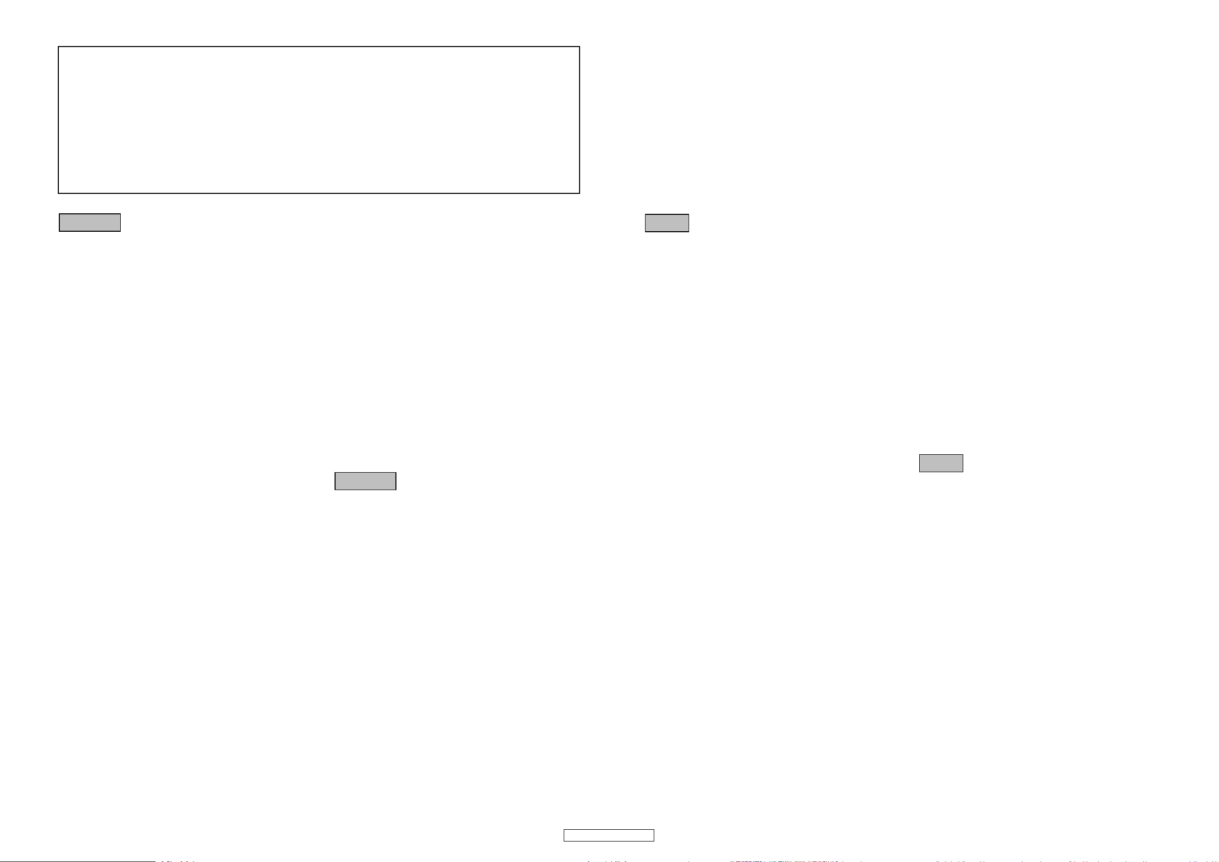
DIMENSION
WIRE ARRANGEMENT
If wire bundles are untied or moved to perform adjustment or parts replacement etc., be sure to rearrange
them neatly as they were originally bundled or placed afterward.
Otherwise, incorrect arrangement can be a cause of noise generation.
Wire arrangement viewed from the top
4
DVD-2500BTCI

Item
HDMI Output
Note:
1. Power supply: AC 120 V, 60 Hz
SPECIFICATIONS
Output jack: 19-pin HDMI terminal, 1 set
HDMI (Deep Color, Dolby Digital Plus, Dolby TrueHD, DTSHD)
5
DVD-2500BTCI
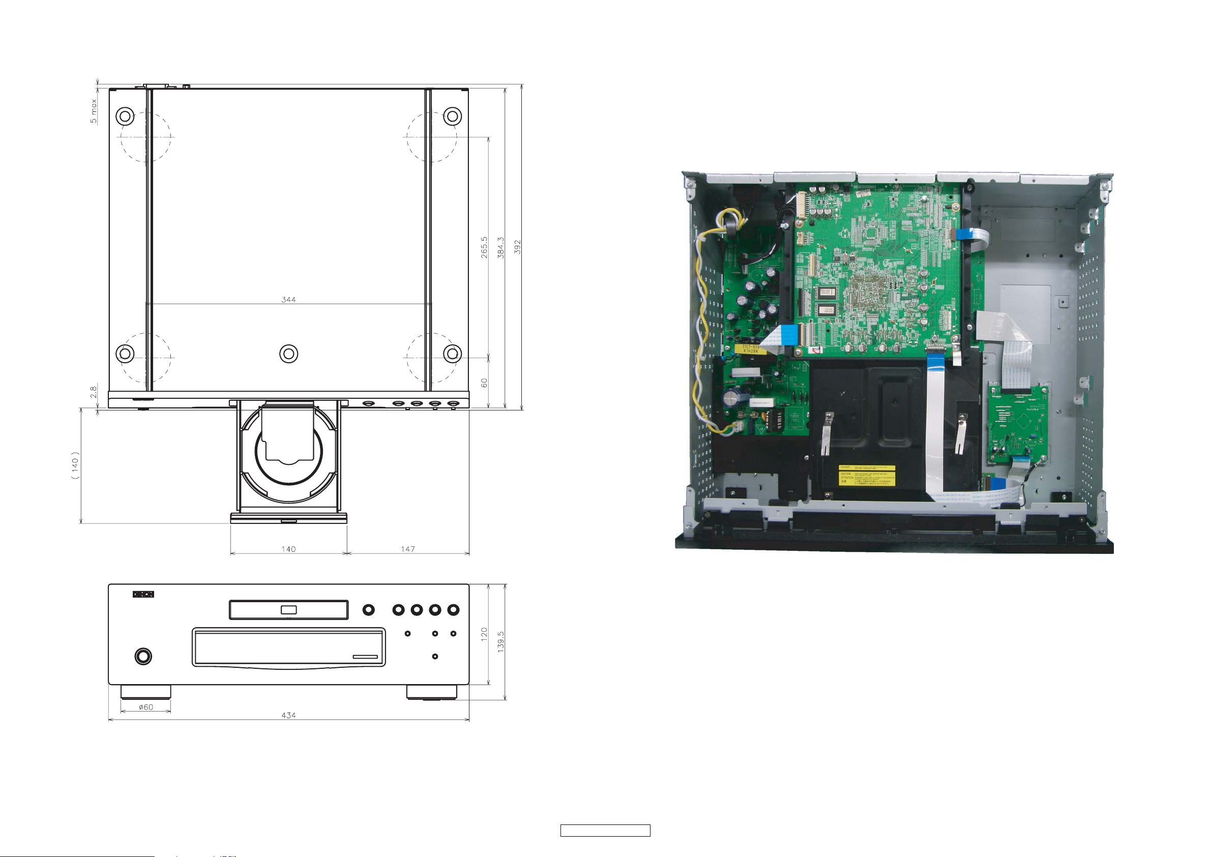
LASER BEAM SAFETY PRECAUTIONS
This BD player uses a pickup that emits a laser beam.
Do not look directly at the laser beam coming
from the pickup or allow it to strike against your
skin.
The laser beam is emitted from the location shown in the figure. When checking the laser diode, be sure to keep
your eyes at least 30 cm away from the pickup lens when the diode is turned on. Do not look directly at the laser
beam.
CAUTION: Use of controls and adjustments, or doing procedures other than those specified herein, may result in
hazardous radiation exposure.
Drive Mechanism Assembly
Laser Beam Radiation
Laser Pickup
Turntable
WHEN OPEN. DO NOT
Location: Top of BD mechanism.
CAUTION
LASER RADIATION
STARE INTO BEAM.
6
DVD-2500BTCI
Safety Check after Servicing
Examine the area surrounding the repaired location for damage or deterioration. Observe that screws, parts, and
wires have been returned to their original positions. Afterwards, do the following tests and confirm the specified
values to verify compliance with safety standards.
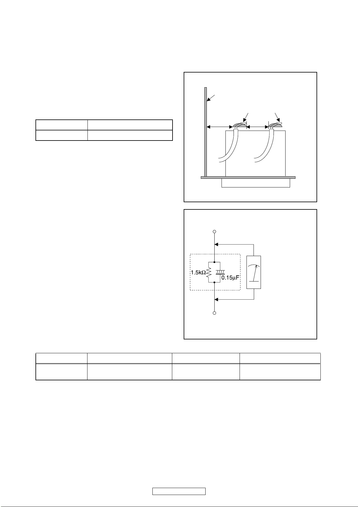
1. Clearance Distance
When replacing primary circuit components, confirm
specified clearance distance (d) and (d’) between
soldered terminals, and between terminals and
surrounding metallic parts. (See Fig. 1)
Table 1: Ratings for selected area
Chassis or Secondary Conductor
Primary Circuit
AC Line Voltage Clearance Distance (d), (d’)
120 V ≥ 3.2 mm (0.126 inches)
Note: This table is unofficial and for reference only. Be
sure to confirm the precise values.
2. Leakage Current Test
Confirm the specified (or lower) leakage current
between B (earth ground, power cord plug prongs) and
externally exposed accessible parts (RF terminals,
antenna terminals, video and audio input and output
terminals, microphone jacks, earphone jacks, etc.) is
lower than or equal to the specified value in the table
below.
Measuring Method (Power ON):
Insert load Z between B (earth ground, power cord plug
prongs) and exposed accessible parts. Use an AC
voltmeter to measure across the terminals of load Z.
See Fig. 2 and the following table.
d' d
Fig. 1
Exposed Accessible Part
Z
AC Voltmeter
(High Impedance)
Earth Ground
B
Power Cord Plug Prongs
Table 2: Leakage current ratings for selected areas
AC Line Voltage Load Z Leakage Current (i) Earth Ground (B) to:
120 V
Note: This table is unofficial and for reference only. Be sure to confirm the precise values.
0.15 μF CAP. & 1.5 kΩ RES.
Connected in parallel
i ≤ 0.5 mA Peak Exposed accessible parts
7
DVD-2500BTCI
Fig. 2
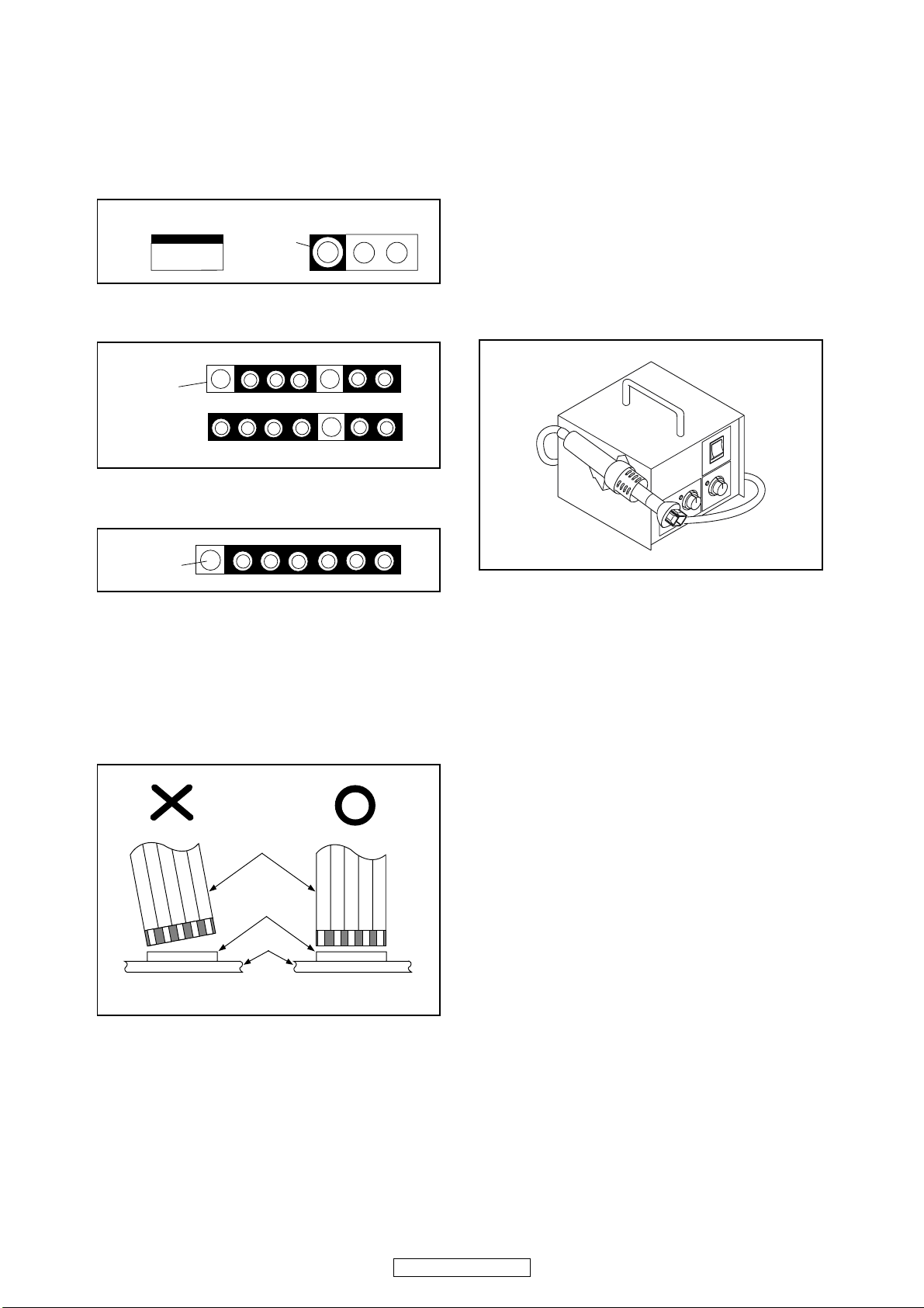
STANDARD NOTES FOR SERVICING
Circuit Board Indications
1. The output pin of the 3 pin Regulator ICs is
indicated as shown.
Top View
Out
2. For other ICs, pin 1 and every fifth pin are
indicated as shown.
Pin 1
3. The 1st pin of every male connector is indicated as
shown.
Pin 1
Input
In
Bottom View
5
10
Pb (Lead) Free Solder
When soldering, be sure to use the Pb free solder.
How to Remove / Install Flat Pack-IC
1. Removal
With Hot-Air Flat Pack-IC Desoldering Machine:
1. Prepare the hot-air flat pack-IC desoldering
machine, then apply hot air to the Flat Pack-IC
(about 5 to 6 seconds). (Fig. S-1-1)
Fig. S-1-1
Instructions for Connectors
1. When you connect or disconnect the FFC (Flexible
Foil Connector) cable, be sure to first disconnect
the AC cord.
2. FFC (Flexible Foil Connector) cable should be
inserted parallel into the connector, not at an
angle.
FFC Cable
Connector
CBA
* Be careful to avoid a short circuit.
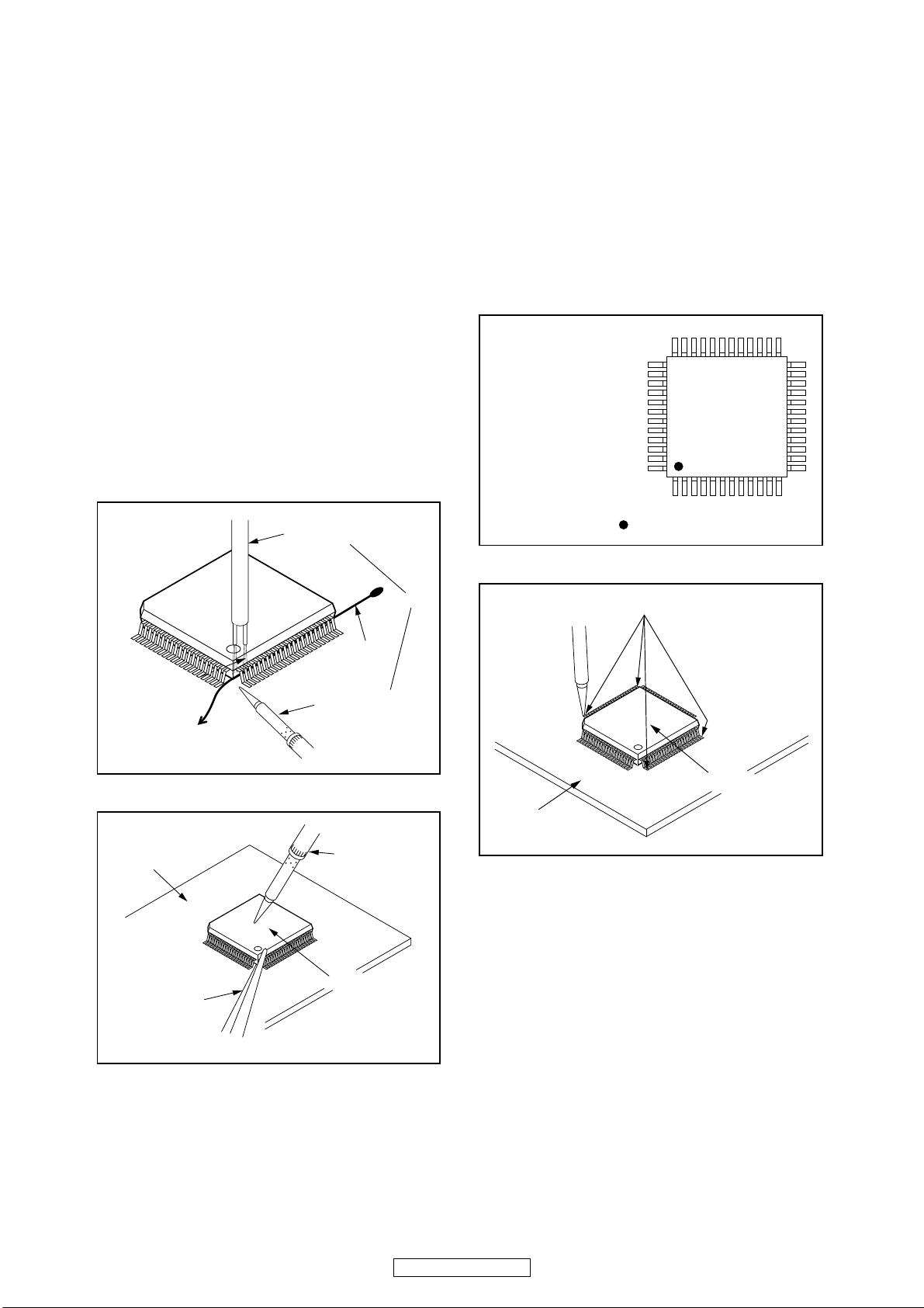
2. Remove the flat pack-IC with tweezers while
applying the hot air.
3. Bottom of the flat pack-IC is fixed with glue to the
CBA; when removing entire flat pack-IC, first apply
soldering iron to center of the flat pack-IC and heat
up. Then remove (glue will be melted). (Fig. S-1-6)
4. Release the flat pack-IC from the CBA using
tweezers. (Fig. S-1-6)
CAUTION:
1. The Flat Pack-IC shape may differ by models. Use
an appropriate hot-air flat pack-IC desoldering
machine, whose shape matches that of the Flat
Pack-IC.
2. Do not supply hot air to the chip parts around the
flat pack-IC for over 6 seconds because damage
to the chip parts may occur. Put masking tape
around the flat pack-IC to protect other parts from
damage. (Fig. S-1-2)
8
DVD-2500BTCI
With Iron Wire:
1. Using desoldering braid, remove the solder from
all pins of the flat pack-IC. When you use solder
flux which is applied to all pins of the flat pack-IC,
you can remove it easily. (Fig. S-1-3)
2. Affix the wire to a workbench or solid mounting
point, as shown in Fig. S-1-5.
3. While heating the pins using a fine tip soldering
iron or hot air blower, pull up the wire as the solder
melts so as to lift the IC leads from the CBA
contact pads as shown in Fig. S-1-5.
4. Bottom of the flat pack-IC is fixed with glue to the
CBA; when removing entire flat pack-IC, first apply
soldering iron to center of the flat pack-IC and heat
up. Then remove (glue will be melted). (Fig. S-1-6)
5. Release the flat pack-IC from the CBA using
tweezers. (Fig. S-1-6)
Note: When using a soldering iron, care must be
taken to ensure that the flat pack-IC is not
being held by glue. When the flat pack-IC is
removed from the CBA, handle it gently
because it may be damaged if force is applied.
Hot Air Blower
2. Installation
1. Using desoldering braid, remove the solder from
the foil of each pin of the flat pack-IC on the CBA
so you can install a replacement flat pack-IC more
easily.
2. The “●” mark on the flat pack-IC indicates pin 1.
(See Fig. S-1-7.) Be sure this mark matches the 1
on the PCB when positioning for installation. Then
presolder the four corners of the flat pack-IC. (See
Fig. S-1-8.)
3. Solder all pins of the flat pack-IC. Be sure that
none of the pins have solder bridges.
Example :
Pin 1 of the Flat Pack-IC
is indicated by a " " mark.
Fig. S-1-7
To Solid
Mounting Point
CBA
Tweezers
Iron Wire
Soldering Iron
Fig. S-1-5
Fine Tip
Soldering Iron
Flat Pack-IC
or
Presolder
Flat Pack-IC
CBA
Fig. S-1-8
Fig. S-1-6
DVD-2500BTCI
9
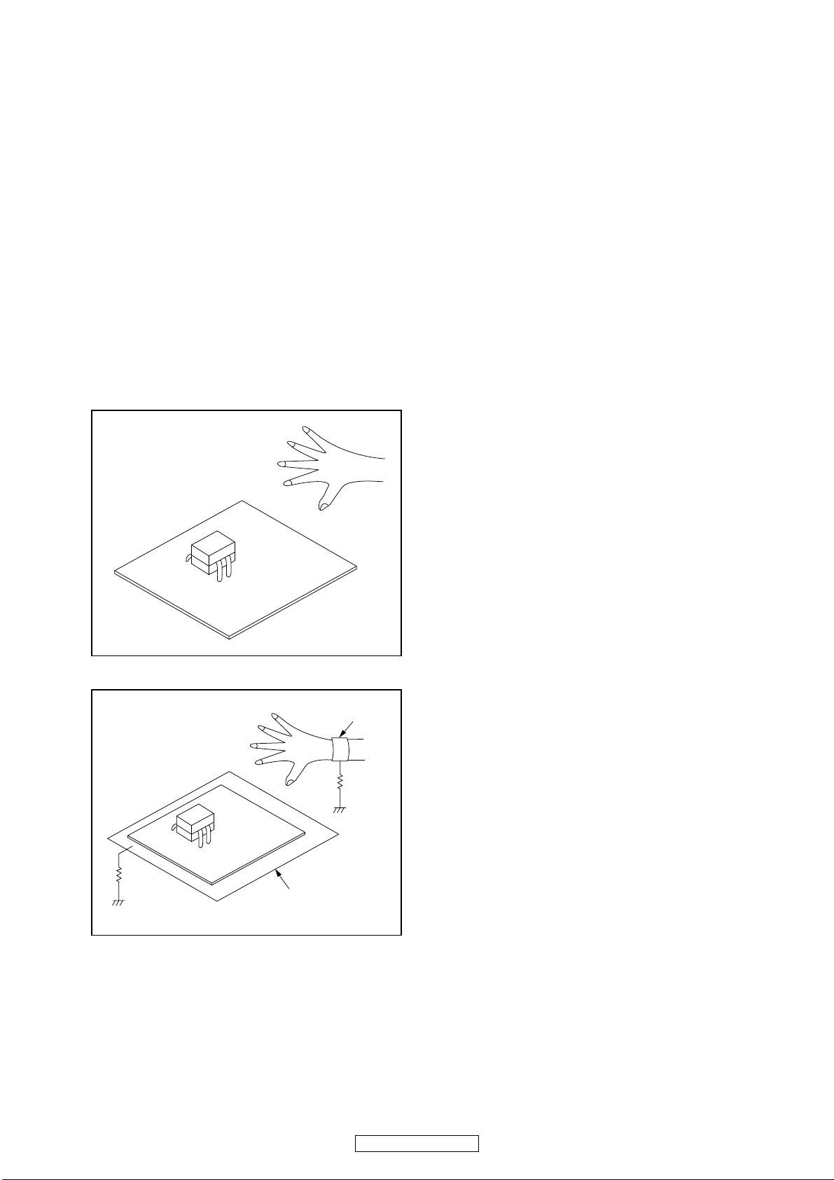
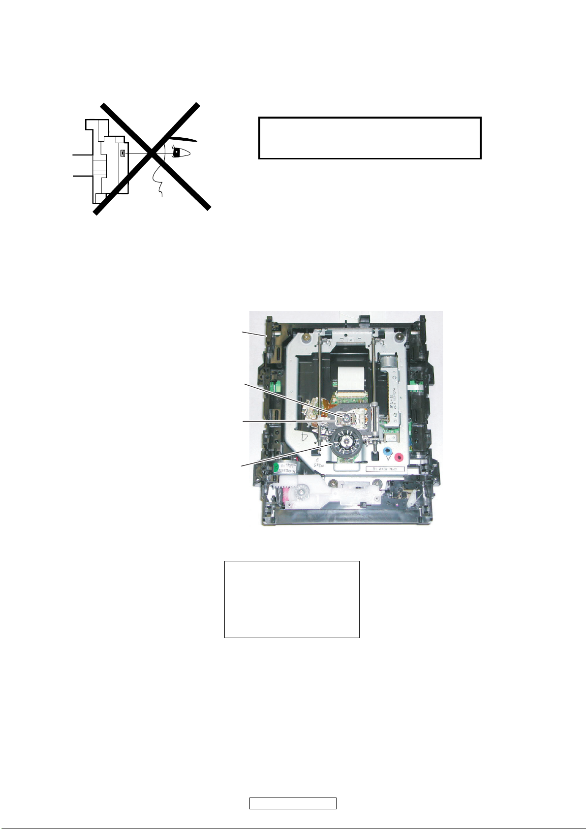
Instructions for Handling Semiconductors
Electrostatic breakdown of the semi-conductors may
occur due to a potential difference caused by
electrostatic charge during unpacking or repair work.
1. Ground for Human Body
Be sure to wear a grounding band (1 MΩ) that is
properly grounded to remove any static electricity that
may be charged on the body.
2. Ground for Workbench
Be sure to place a conductive sheet or copper plate
with proper grounding (1 MΩ) on the workbench or
other surface, where the semi-conductors are to be
placed. Because the static electricity charge on
clothing will not escape through the body grounding
band, be careful to avoid contacting semi-conductors
with your clothing.
<Incorrect>
<Correct>
1MΩ
CBA
Grounding Band
1MΩ
CBA
Conductive Sheet or
Copper Plate
10
DVD-2500BTCI
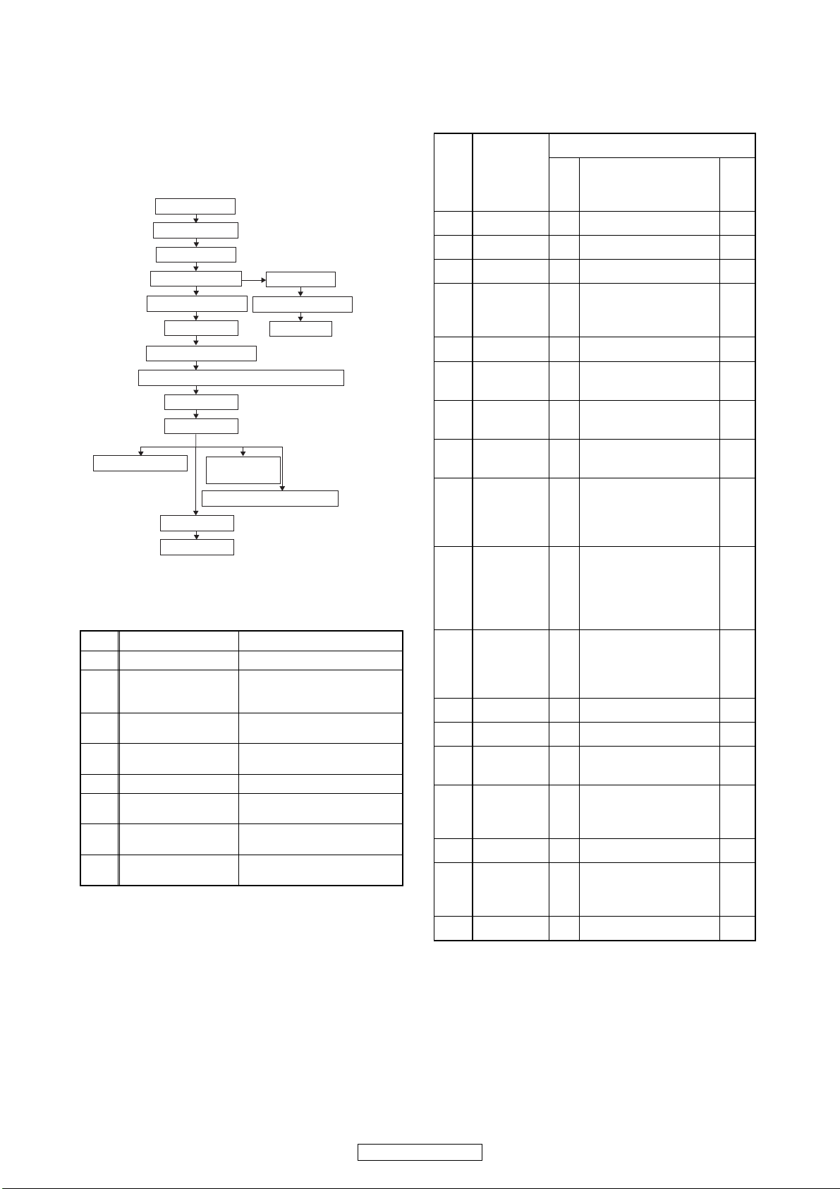
CABINET DISASSEMBLY INSTRUCTIONS
1. Disassembly Flowchart
This flowchart indicates the disassembly steps to gain
access to item(s) to be serviced. When reassembling,
follow the steps in reverse order. Bend, route, and
dress the cables as they were originally.
[1] Top Cover
[2] Top Panel
[3] Tray Panel
[4] Front Assembly
[8] Front Bracket
[9] Rear Panel
[10] BE Main CBA Unit
[11] FE Main CBA & BD Mechanism Assembly
[12] Fan Holder
[13] Fan Motor
[14] RS232C CBA
[16] AV CBA
[18] Pedestal
[15] Power
Supply CBA
[17] Sub Microcontroller CBA
[5] Front CBA
[6] Power SW CBA
[7] SD CBA
2. Disassembly of Main parts
When replacing the main parts, see the following pro-
cedures. For more details, refer to Fig. D1~D9.
Part Steps
[10] BE Main CBA Unit [1] ψ [2] ψ *[9](S-14) ψ [10]
FE Main CBA & BD
[11]
Mechanism
Assembly
[12] Fan Holder
[13] Fan Motor
[14] RS232C CBA [1] ψ [2] ψ [9] ψ [10] ψ [14]
[15] Power Supply CBA
[16] AV CBA
Sub Microcontroller
[17]
CBA
*About *[9](S-14), remove only (S-14) of Rear Panel.
Note: Be sure to unplug the power cord from the
power outlet before disassembling.
“Current continues to flow in the set for 10
to 20 seconds after the power cord is
unplugged. Wait until the power LED turns
completely off before proceeding.”
[1] ψ [2] ψ [3] ψ *[9](S-14) ψ
[10] ψ [11]
[1] ψ [2] ψ *[9](S-14) ψ [10] ψ
[12]
[1] ψ [2] ψ *[9](S-14) ψ [10] ψ
[12] ψ [13]
[1] ψ [2] ψ *[9](S-14) ψ [12] ψ
[15]
[1]ψ[2]ψ [3]ψ [9]ψ [10]ψ [11]
ψ [12] ψ [13] ψ [14] ψ [16]
[1] ψ [2] ψ [17]
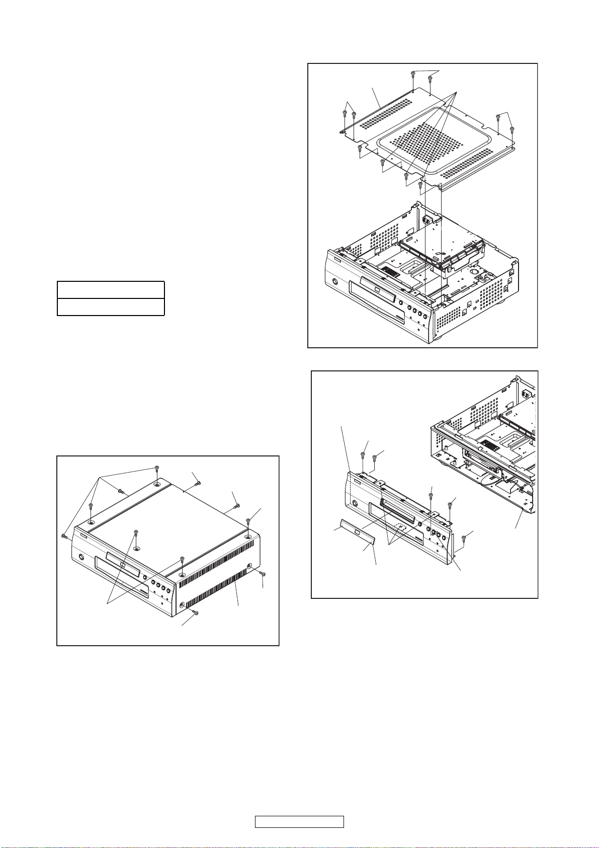
3. Disassembly Method
ID/
Loc.
No.
Part
Fig.
No.
[1] Top Cover D1 9(S-1), 2(S-2) ---
[2] Top Panel D2 10(S-3) ---
[3] Tray Panel D3 *2(L-1) 1
2(S-4), 2(S-5), (S-5a),
D3
*3(L-2), *CN2001,
*CN4002
[4]
Front
Assembly
[5] Front CBA D4 7(S-6) ---
Power SW
[6]
CBA
[7] SD CBA D4
Front
[8]
Bracket
D4 2(S-7), Desolder ---
2(S-8), SD PCB
Holder
D5 2(S-9) ---
2(S-10), 2(S-11),
[9] Rear Panel D5
2(S-12), (S-13),
(S-14), 3(S-15),
*CN1003
4(S-16), 4(S-17),
3(S-18), *CN6401,
D6
*CN7001, *CN7401,
BE Scaler Holder, BE
[10]
BE Main
CBA Unit
Scaler Sub Holder
FE Main
CBA & BD
[11]
Mechanism
D7 4(S-19), *CN2601 ---
Assembly
[12] Fan Holder D7 2(S-20), *CN2500 ---
[13] Fan Motor D7 2(S-21) ---
[14]
[15]
RS232C
CBA
Power
Supply
CBA
3(S-22), *CN2551,
D8
RS232C Holder
2(S-23), 2(S-24),
D8
2(S-25), *CN2501,
Power PCB Holder
[16] AV CBA D8 7(S-26), *CN2503 ---
Sub
[17]
Microcontro
D9 4(S-27) ---
ller CBA
[18] Pedestal D9 3(S-28) ---
p
(1)
p
(2)
p
(3)
Removal
Remove/*Unhook/
Unlock/Release/
Unplug/Desolder
p
(4)
Note
1
---
2
2
---
---
p
(5)
11
DVD-2500BTCI
Note:
(1) Identification (location) No. of parts in the figures
(2) Name of the part
(3) Figure Number for reference
(4) Identification of parts to be removed, unhooked,
unlocked, released, unplugged, unclamped, or
desoldered.
P = Spring, L = Locking Tab, S = Screw,
CN = Connector
* = Unhook, Unlock, Release, Unplug, or Desolder
e.g. 2(S-2) = two Screws (S-2),
2(L-2) = two Locking Tabs (L-2)
(5) Refer to “Reference Notes.”
About tightening screws
When tightening screws, tighten them with the
following torque.
Torque
0.45 ± 0.05 N·m
Reference Notes
1. CAUTION 1: Locking Tabs (L-1) and (L-2) are
fragile. Be careful not to break them.
1) Release three Locking Tabs (L-2).
2) Disconnect connectors CN2001, CN4002, then
remove the Front Assembly.
2. CAUTION 2: When installing the BE Main CBA
Unit with a screw, hold and press the BE Main
CBA Unit to align the HDMI connector with the
connector’s hole for HDMI on the Rear Panel.
[2] Top Panel
(S-3)
[4] Front Assembly
(S-4)
(S-5)
(S-3)
(S-3)
(S-3)
Fig. D2
(S-1)
(S-1)
(S-1)
(S-2)
(S-2)
(S-1)
(S-1)
[1] Top Cover
Fig. D1
(L-1)
(L-1)
(L-2)
[3] Tray Panel
(S-5a)
(S-4)
(S-5)
CN2001
CN4002
Fig. D3
12
DVD-2500BTCI
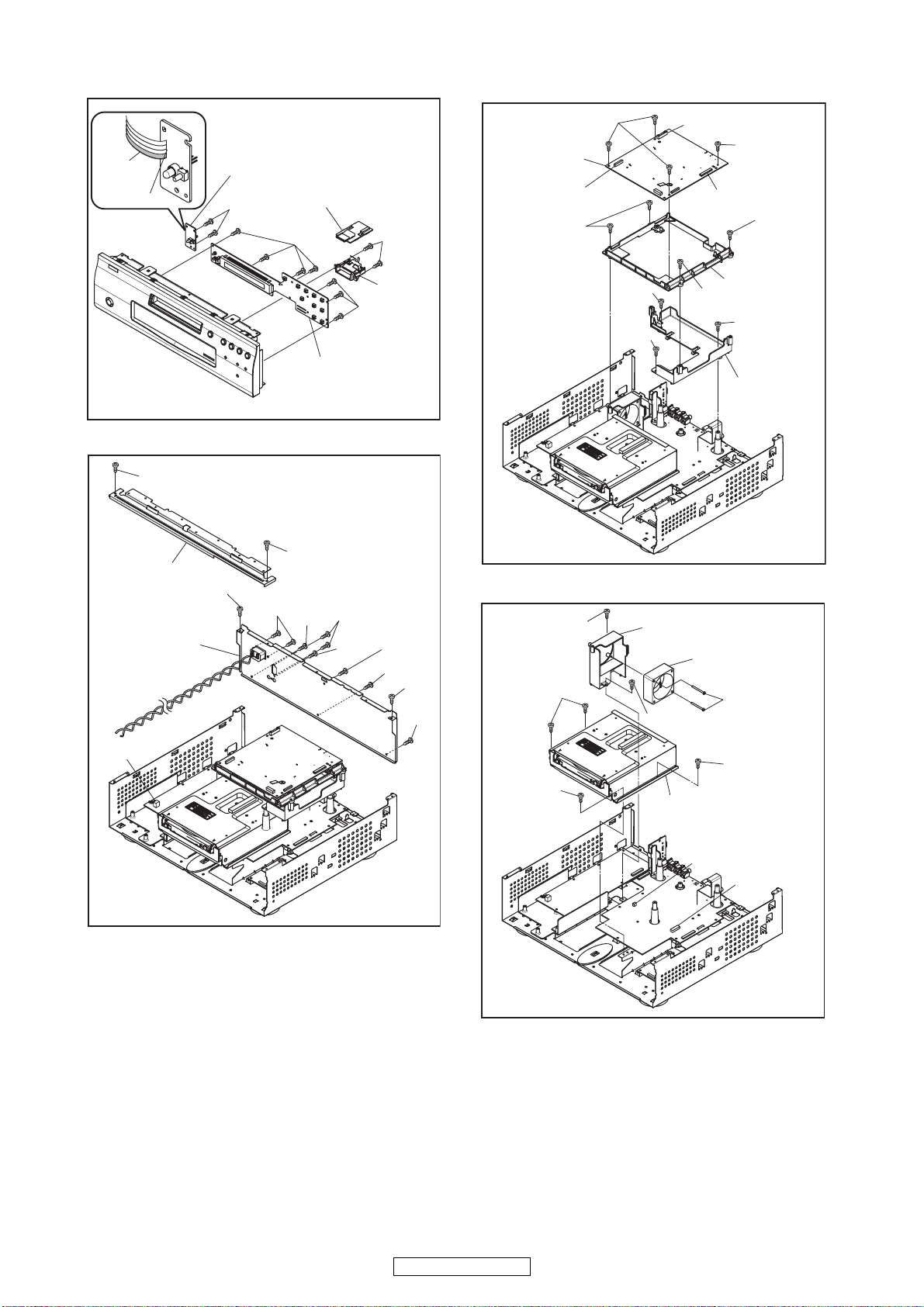
Lead with
blue stripe
Desolder
[6] Power SW CBA
(S-7)
[7] SD CBA
(S-6)
(S-8)
[10] BE Main
CBA Unit
CN6401
(S-17)
(S-16)
CN7401
(S-16)
CN7001
(S-17)
(S-9)
[8] Front Bracket
(S-10)
[9] Rear Panel
[5] Front CBA
(S-9)
(S-12)
(S-15)
(S-11)
(S-13)
(S-6)
Fig. D4
SD PCB
Holder
(S-14)
(S-15)
(S-10)
(S-15)
(S-20)
(S-19)
(S-18)
(S-18)
[12] Fan Holder
(S-20)
BE Scaler
(S-17)
Holder
(S-18)
BE Scaler
Sub Holder
[13] Fan Motor
(S-21)
Fig. D6
CN1003
(S-19)
(S-19)
[11] FE Main CBA &
BD Mechanism Assembly
CN2500
CN2601
Fig. D5
Fig. D7
13
DVD-2500BTCI
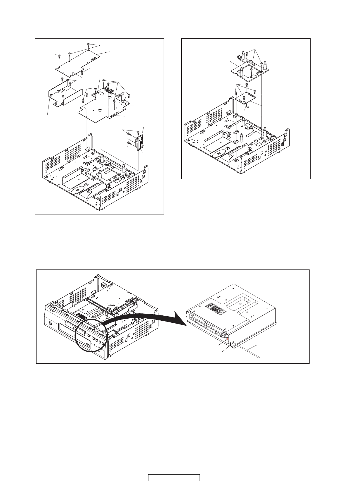
(S-24)
(S-25)
(S-26)
(S-24)
CN2501
(S-23)
[15] Power Supply
CBA
(S-26)
(S-28)
[18] Pedestal
(S-27)
[16] AV
CBA
Power PCB
Holder
(S-22)
CN2503
[14] RS232C CBA
CN2551
(S-22)
RS232C
Holder
Fig. D8
4. How to Eject Manually
1. Remove the Top Cover and the Top Panel.
2. Insert a screwdriver, etc. into the Hole A straightly so that the Portion A is pushed.
3. Pull the tray out manually and remove a disc.
Wire
[17] Sub
Microcontroller
CBA
Fig. D9
14
DVD-2500BTCI
Portion A
Hole A
Screwdriver,
hexagon wrench
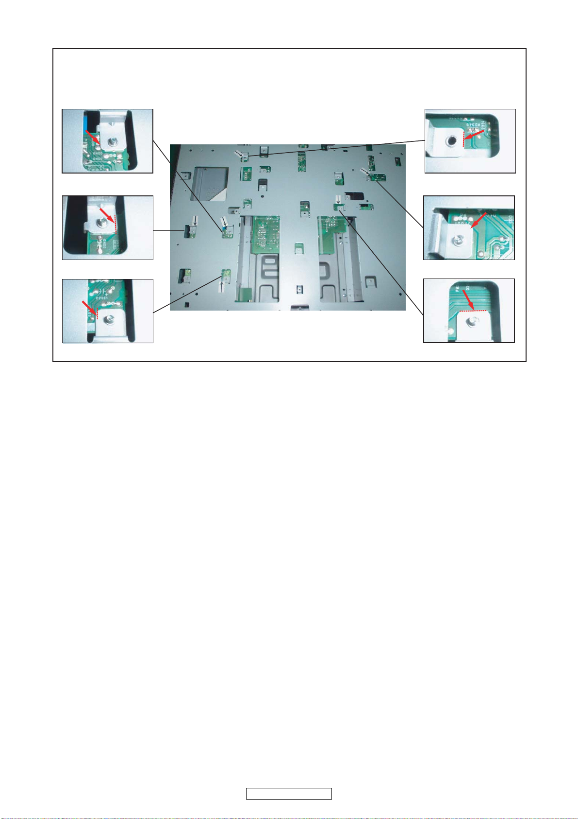
Cautions concerning the structure
The chassis touches the patterns on the circuit board at 6 points, but these patterns are all ground patterns,
so performance is not affected.
View from the bottom
15
DVD-2500BTCI
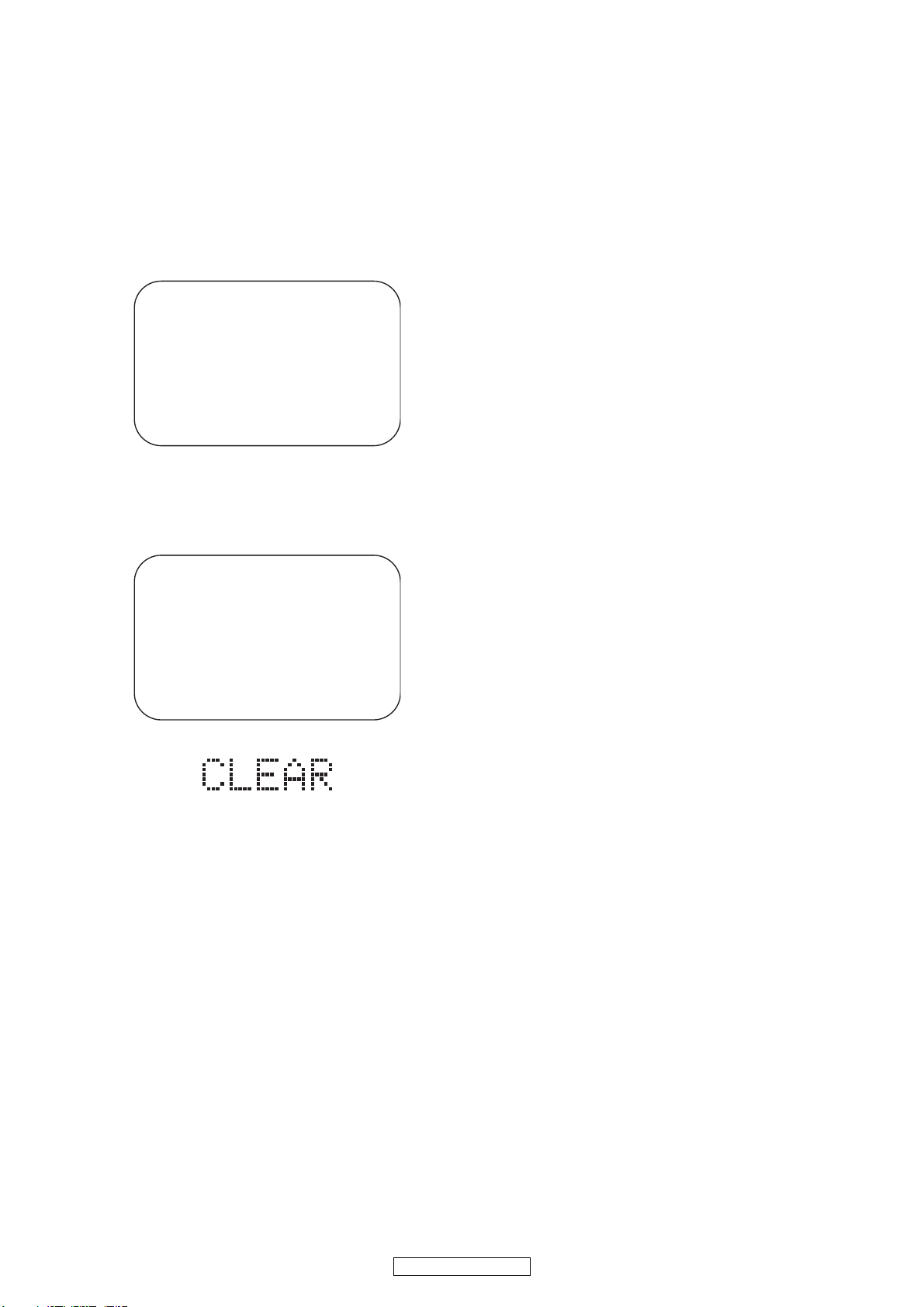
HOW TO INITIALIZE THE BLU-RAY DISC PLAYER
To put the program back at the factory-default,
initialize the BD player as the following procedure.
1. Turn the power on by pressing the [POWER]
button and the tray will close.
2. Press [1], [2], [3], [4], and [DISPLAY] buttons on
the remote control unit in that order.
Fig. a appears on the screen.
"
" differ depending on the models.
*******
MODEL : *******
Version
Region
3. Press [STOP] button on the remote control unit.
Fig. b appears on the screen and Fig. c appears
on the VFD.
: *.***
: * / *
Fig. a
"
" differ depending on the models.
*******
EXIT: POWEREEPROM CLEAR : STOP
MODEL : *******
Version
Region
EEPROM CLEAR : OK
: *.***
: * / *
EXIT: POWEREEPROM CLEAR : STOP
Fig. b
Fig. c
4. To exit this mode, press [POWER OFF] button.
16
DVD-2500BTCI
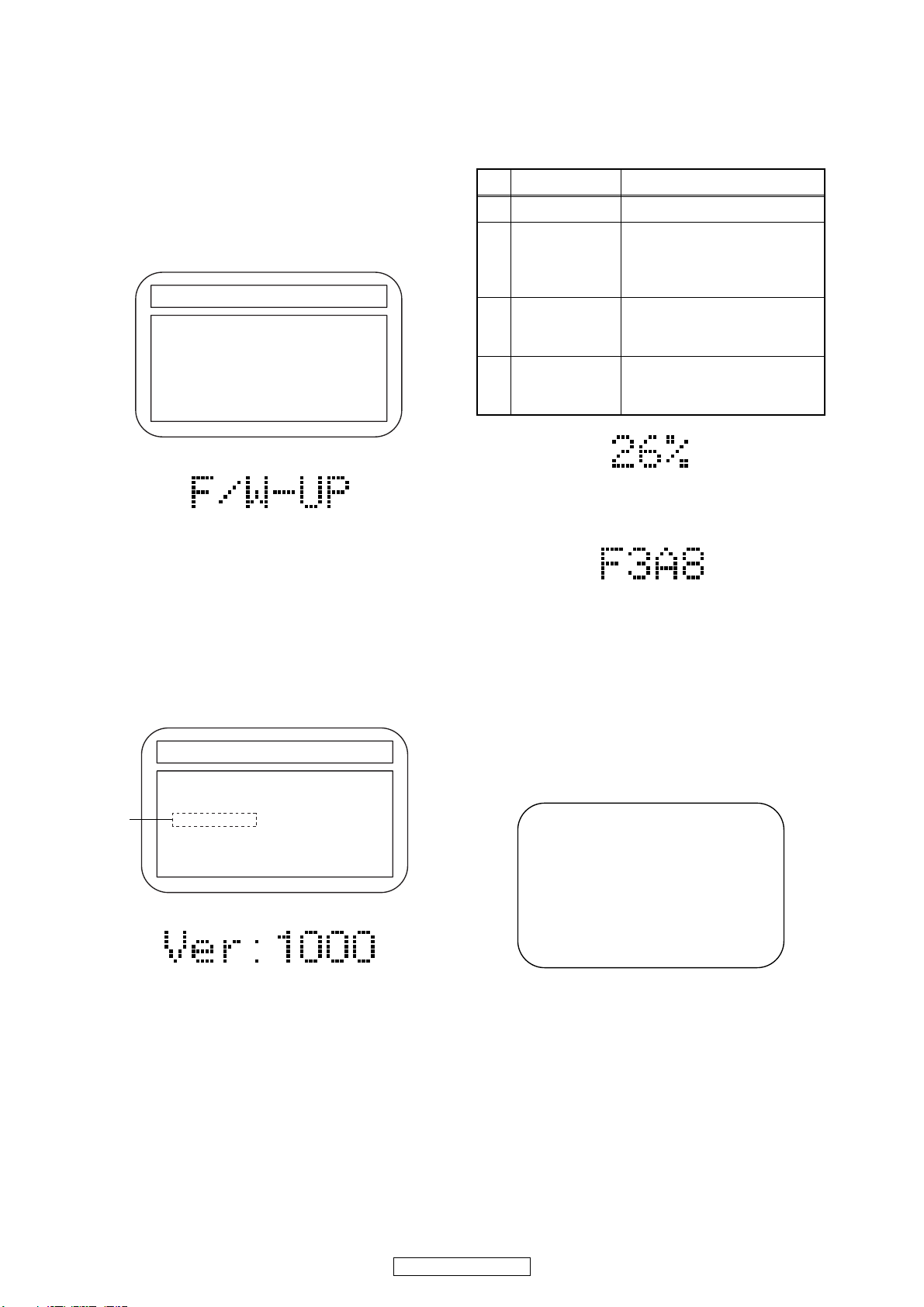
FIRMWARE RENEWAL MODE
1. Turn the power on and remove the disc on the tray.
2. To put the BD player into version up mode, press
[9], [8], [7], [6], and [MENU/POP MENU] buttons
on the remote control unit in that order. The tray
will open automatically.
Fig. a appears on the screen and Fig. b appears
on the VFD.
"
" differs depending on the models.
*******
F/W VERSION UP MODE Model No : ******* VERSION : *.***
Please insert a DISC
for F/W Version Up.
Fig. a Version Up Mode Screen
Fig. b VFD in Version Up Mode
The BD player can also enter the version up mode
with the tray open. In this case, Fig. a will be
shown on the screen while the tray is open.
3. Load the disc for version up.
4. The BD player enters the F/W version up mode
automatically. Fig. c appears on the screen and
Fig. d appears on the VFD. If you enter the F/W for
different models, “Disc Error” will appear on the
screen, then the tray will open automatically.
"
" differs depending on the models.
*******
F/W VERSION UP MODE Model No : ******* VERSION : *.***
1. ALL
VERSION : *.** ************A*.bin
(*1)
Now Loading...
The appearance shown in (*1) of Fig. c is
described as follows:
No. Appearance State
1 Now Loading... Loading the disc
Sending files into the
2 Reading...
memory.
After reading, automatically
the tray opens.
Remove the
3
disc
Reading has finished.
Remove the disc and close
the tray.
Writing new version data,
4 See FL display
the progress will be displayed
as shown in Fig. e.
Fig. e VFD in Version Up Mode
5. After programming is finished, the checksum on
the VFD (Fig. f).
Fig. f VFD upon Finishing the Programming Mode (Example)
At this time, no button is available.
6. Unplug the AC cord from the AC outlet. Then plug
it again.
7. Turn the power on by pressing the [POWER ON]
button and the tray will close.
8. Press [1], [2], [3], [4], and [DISPLAY] buttons on
the remote control unit in that order.
Fig. g appears on the screen.
"
" differ depending on the models.
*******
MODEL : *******
Version
Region
: *.***
: * / *
Fig. c Programming Mode Screen (Example)
Fig. d VFD in Programming Mode (Example)
EXIT: POWEREEPROM CLEAR : STOP
Fig. g
17
DVD-2500BTCI

9. Press [STOP] button on the remote control unit.
Fig. h appears on the screen and Fig. i appears on
the VFD.
"
" differ depending on the models.
*******
MODEL : *******
Version
Region
EEPROM CLEAR : OK
: *.***
: * / *
EXIT: POWEREEPROM CLEAR : STOP
Fig. h
Fig. i
10. To exit this mode, press [POWER OFF] button.
18
DVD-2500BTCI
 Loading...