

Page 1
AV SURROUND RECEIVER
AVR-590
Owner’s Manual
Manuel de l’Utilisateur
bThe illustrations used for explaining operations in this manual show the buttons of
the remote control unit.
The same operations can be performed using the buttons with the same names on
the main unit panel.
b Les illustrations des boutons présentes dans ce manuel servent à expliquer le
fonctionnement de la télécommande.
Vous pouvez contrôler l’appareil à l’aide du bouton portant le même nom sur la
façade de l’appareil.
Page 2
CAUTION
RISK OF ELECTRIC SHOCK
DO NOT OPEN
ENGLISH FRANCAIS
SAFETY PRECAUTIONS
n
CAUTION:
TO REDUCE THE RISK OF ELECTRIC SHOCK, DO NOT REMOVE
COVER (OR BACK). NO USER-SERVICEABLE PARTS INSIDE.
REFER SERVICING TO QUALIFIED SERVICE PERSONNEL.
The lightning flash with arrowhead symbol, within an equilateral
triangle, is intended to alert the user to the presence of
uninsulated “dangerous voltage” within the product’s enclosure
that may be of sufficient magnitude to constitute a risk of electric
shock to persons.
The exclamation point within an equilateral triangle is intended
to alert the user to the presence of important operating
and maintenance (servicing) instructions in the literature
accompanying the appliance.
WARNING:
TO REDUCE THE RISK OF FIRE OR ELECTRIC SHOCK, DO NOT
EXPOSE THIS APPLIANCE TO RAIN OR MOISTURE.
CAUTION:
HOT SURFACE. DO NOT TOUCH.
The top surface over the internal heat sink may become
hot when operating this product continuously.
PRECAUTION:
SURFACE CHAUDE. NE PAS TOUCHER.
La surface supérieure du dissipateur de chaleur peut
devenir chaude si vous utilisez ce produit en continu.
IMPOTANT SAFETY
INSTRUCTIONS
1. Read these instructions.
2. Keep these instructions.
3. Heed all warnings.
4. Follow all instructions.
5. Do not use this apparatus near water.
6. Clean only with dry cloth.
7. Do not block any ventilation openings.
Install in accordance with the manufacturer’s instructions.
8. Do not install near any heat sources such as radiators, heat registers,
stoves, or other apparatus (including amplifiers) that produce heat.
9. Do not defeat the safety purpose of the polarized or grounding-type plug. A
polarized plug has two blades with one wider than the other. A grounding
type plug has two blades and a third grounding prong. The wide blade or the
third prong are provided for your safety. If the provided plug does not fit into
your outlet, consult an electrician for replacement of the obsolete outlet.
10. Protect the power cord from being walked on or pinched particularly at
plugs, convenience receptacles, and the point where they exit from the
apparatus.
11. Only use attachments/accessories specified by the manufacturer.
12. Use only with the cart, stand, tripod, bracket, or table
specified by the manufacturer, or sold with the apparatus.
When a cart is used, use caution when moving the cart/
apparatus combination to avoid injury from tip-over.
13. Unplug this apparatus during lightning storms or when
unused for long periods of time.
14. Refer all servicing to qualified service personnel.
Servicing is required when the apparatus has been damaged in any way,
such as power-supply cord or plug is damaged, liquid has been spilled or
objects have fallen into the apparatus, the apparatus has been exposed to
rain or moisture, does not operate normally, or has been dropped.
15. Batteries shall not be exposed to excessive heat such as sunshine, fire or
the like.
CAUTION:
• The ventilation should not be impeded by covering the ventilation
openings with items, such as newspapers, tablecloths, curtains,
etc.
• No naked flame sources, such as lighted candles, should be
placed on the unit.
• Observe and follow local regulations regarding battery disposal.
• Do not expose the unit to dripping or splashing fluids.
• Do not place objects filled with liquids, such as vases, on the
unit.
ATTENTION:
• La ventilation ne doit pas être gênée en recouvrant les ouvertures
de la ventilation avec des objets tels que journaux, rideaux, tissus,
etc.
• Aucune flamme nue, par exemple une bougie, ne doit être placée
sur l’appareil.
• Veillez à respecter les lois en vigueur lorsque vous jetez les piles
usagées.
• L’appareil ne doit pas être exposé à l’eau ou à l’humidité.
• Ne pas poser d’objet contenant du liquide, par exemple un vase,
sur l’appareil.
CAUTION:
To completely disconnect this product from the mains, disconnect
the plug from the wall socket outlet.
The mains plug is used to completely interrupt the power supply to
the unit and must be within easy access by the user.
PRECAUTION:
Pour déconnecter complètement ce produit du courant secteur,
débranchez la prise de la prise murale.
La prise secteur est utilisée pour couper complètement
l’alimentation de l’appareil et l’utilisateur doit pouvoir y accéder
facilement.
I
Page 3
FCC INFORMATION (For US customers)
1. PRODUCT
This product complies with Part 15 of the FCC Rules. Operation is subject to the following two conditions: (1) this
product may not cause harmful interference, and (2) this product must accept any interference received, including
interference that may cause undesired operation.
2. IMPORTANT NOTICE: DO NOT MODIFY THIS PRODUCT
This product, when installed as indicated in the instructions contained in this manual, meets FCC requirements.
Modification not expressly approved by DENON may void your authority, granted by the FCC, to use the product.
3. NOTE
This product has been tested and found to comply with the limits for a Class B digital device, pursuant to Part 15
of the FCC Rules. These limits are designed to provide reasonable protection against harmful interference in a
residential installation.
This product generates, uses and can radiate radio frequency energy and, if not installed and used in accordance
with the instructions, may cause harmful interference to radio communications. However, there is no guarantee
that interference will not occur in a particular installation. If this product does cause harmful interference to radio or
television reception, which can be determined by turning the product OFF and ON, the user is encouraged to try to
correct the interference by one or more of the following measures:
• Reorient or relocate the receiving antenna.
• Increase the separation between the equipment and receiver.
• Connect the product into an outlet on a circuit different from that to which the receiver is connected.
• Consult the local retailer authorized to distribute this type of product or an experienced radio/TV technician for
help.
This Class B digital apparatus complies with Canadian ICES-003.
Cet appareil numérique de la classe B est conforme à la norme NMB-003 du Canada.
NOTE ON USE / OBSERVATIONS RELATIVES A L’UTILISATION
n
• Do not let foreign objects into the unit.
• Ne pas laisser des objets étrangers dans
l’appareil.
• Do not let insecticides, benzene, and
thinner come in contact with the unit.
• Ne pas mettre en contact des insecticides,
du benzène et un diluant avec l’appareil.
• Avoid high temperatures.
Allow for sufficient heat dispersion when
installed in a rack.
• Eviter des températures élevées.
Tenir compte d’une dispersion de chaleur
suffisante lors de l’installation sur une
étagère.
• Keep the unit free from moisture, water,
and dust.
• Protéger l’appareil contre l’humidité, l’eau
et la poussière.
• Unplug the power cord when not using the
unit for long periods of time.
• Débrancher le cordon d’alimentation
lorsque l’appareil n’est pas utilisé pendant
de longues périodes.
ENGLISHFRANCAIS
• Handle the power cord carefully.
Hold the plug when unplugging the cord.
• Manipuler le cordon d’alimentation avec
précaution.
Tenir la prise lors du débranchement du
cordon.
* (For apparatuses with ventilation holes)
• Do not obstruct the ventilation holes.
• Ne pas obstruer les trous d’aération.
• Never disassemble or modify the unit in
any way.
• Ne jamais démonter ou modifier l’appareil
d’une manière ou d’une autre.
II
Page 4

ENGLISH
n Contents
Getting Started
Flow of operations through playback ········································· 2
Accessories ··················································································2
Cautions on Handling ···································································3
Cautions on Installation ·······························································3
About the Remote Control Unit···················································3
Inserting the Batteries ··································································3
Operating Range of the Remote Control Unit ······························3
Part Names and Functions ··························································· 4
Front Panel ····················································································4
Display ··························································································5
Rear Panel ····················································································· 6
Remote Control Unit ·····································································7
Connections
Important Information ··································································8
Cables Used for Connections ·······················································8
Converting Input video signals for Output (Video Conversion
Function) ·······················································································9
How the on-screen display is displayed depending on the video
input signal····················································································9
Installing/Setting the Speakers ················································· 10
Connecting the Speakers ···························································11
Connecting Devices ····································································12
Connecting Devices not Equipped with HDMI connectors ·····13
Once Connections are Completed ············································· 16
Turning the Power On ································································· 16
Turning the Power Off ································································· 16
Settings
Menu map ···················································································· 17
Examples of On-screen Display and Front Display ·················· 18
Making the Optimum Settings for the Connected Speakers
Automatically (Audyssey Auto Setup) ······································19
Making detailed settings (Manual Setup)·································24
Making the input settings (Input Setup)···································30
Playback
Playing Components ···································································34
Playing Blu-ray Disc / DVD Players ··············································34
iPod® Playback ··········································································· 34
Listening to FM/AM Broadcasts ·················································36
Operations During Playback ························································ 37
Selecting the Surround Mode ····················································37
q Playing sources according to the sources’ audio signal format/
number of channels (Standard Playback) ···································· 37
w Playing in a DENON original surround mode ·························· 38
e Direct Playback ······································································· 38
r Stereo Playback ······································································ 39
Adjusting the Sound Field Effects (Parameter) ························39
Adjusting the sound field effects (Surround Parameter) ·············39
Adjusting the tone (Tone Control) ···············································41
Making the MultEQ, Dynamic EQ and Dynamic Volume settings
(Audyssey Settings) ····································································41
Adjust tonal quality for each speaker using graphic equalizer
(Manual EQ) ················································································42
Restoring compressed audio to nearly pre-compressed conditions
for playback (RESTORER)····························································43
Adjusting the audio delay time while watching the picture (Audio
Delay) ··························································································43
Checking the Status (Information) ·····························43
Convenient functions
HDMI Control Function ·······························································44
Setting the power to standby after a certain amount of time
(Sleep Timer Function) ·······························································44
Playing the picture of a different input source without changing
the currently playing sound (Video Select Function) ·············· 44
Adjust the volume of the different speakers ····························45
Saving frequently used settings (Quick Select Function) ······· 45
Various memory functions ·························································45
Operating the Connected Devices by Remote
Control Unit
Registering Preset Codes ···························································46
Operating Registered Devices ···················································46
Assigning buttons that are Not Used to Operate Other Devices
(Punch Through Function) ··························································48
Other Information ·······························································49
Troubleshooting···································································55
Restoring all the settings to as they were at the time of
purchase (Resetting the Microprocessor) ·································57
Specifications ········································································58
List of preset codes ··································End of this manual
Page 5
Getting Started
t u i o
ENGLISH
Getting Started
Flow of operations through
playback
Perform the operations leading to playback on the AVR-590 in the
order shown below.
Connections
Installing/Setting the Speakers (vpage 10)
⇩
Connecting the Speakers (vpage 11)
⇩
Connecting Devices (vpage 12)
⇩
Turning the Power On (vpage 16)
Settings
Audyssey Auto Setup (vpage 19)
Thank you for purchasing this DENON product. To ensure proper
operation, please read this owner’s manual carefully before using the
product.
After reading them, be sure to keep them for future reference.
Accessories
Check that the following parts are supplied with the product.
qOwner’s manual ...................................................................... 1
wGetting Started ........................................................................1
eWarranty (for North America model only) ................................1
rService station list ................................................................... 1
tRemote control (RC-1120) ........................................................1
yR03/AAA batteries ...................................................................2
uFM indoor antenna .................................................................. 1
iAM loop antenna .....................................................................1
oSetup microphone
(DM-A409, Cord length: Approx. 25 ft / 7.6 m) ......................... 1
Connections Playback Remote Control Information Troubleshooting
Manual Setup (vpage 24)
Perform “Manual Setup” as necessary.b
Input Setup (vpage 30)
Playback
Playing Components (vpage 34)
⇩
Selecting the Surround Mode (vpage 37)
Adjusting the Sound Field Effects (vpage 39)
⇩
SpecificationsSettings
Page 6
ENGLISH
Getting Started
Cautions on Handling Cautions on Installation
• Before turning the power switch on
Check once again that all connections are correct and that there are
Connections Playback Remote Control Information Troubleshooting SpecificationsSettings
no problems with the connection cables.
• Power is supplied to some of the circuitry even when the unit is
set to the standby mode. When traveling or leaving home for long
periods of time, be sure to unplug the power cord from the power
outlet.
• About condensation
If there is a major difference in temperature between the inside of
the unit and the surroundings, condensation (dew) may form on
the operating parts inside the unit, causing the unit not to operate
properly.
If this happens, let the unit sit for an hour or two with the power
turned off and wait until there is little difference in temperature
before using the unit.
• Cautions on using mobile phones
Using a mobile phone near this unit may result in noise. If so, move
the mobile phone away from this unit when it is in use.
• Moving the unit
Turn off the power and unplug the power cord from the power
outlet.
Next, disconnect the connection cables to other system units before
moving the unit.
• Note that the illustrations in these instructions may differ from the
actual unit for explanation purposes.
Note:
For proper heat dispersal, do not install this unit in a confined
space, such as a bookcase or similar enclosure.
b Note
b
b
b
Wall
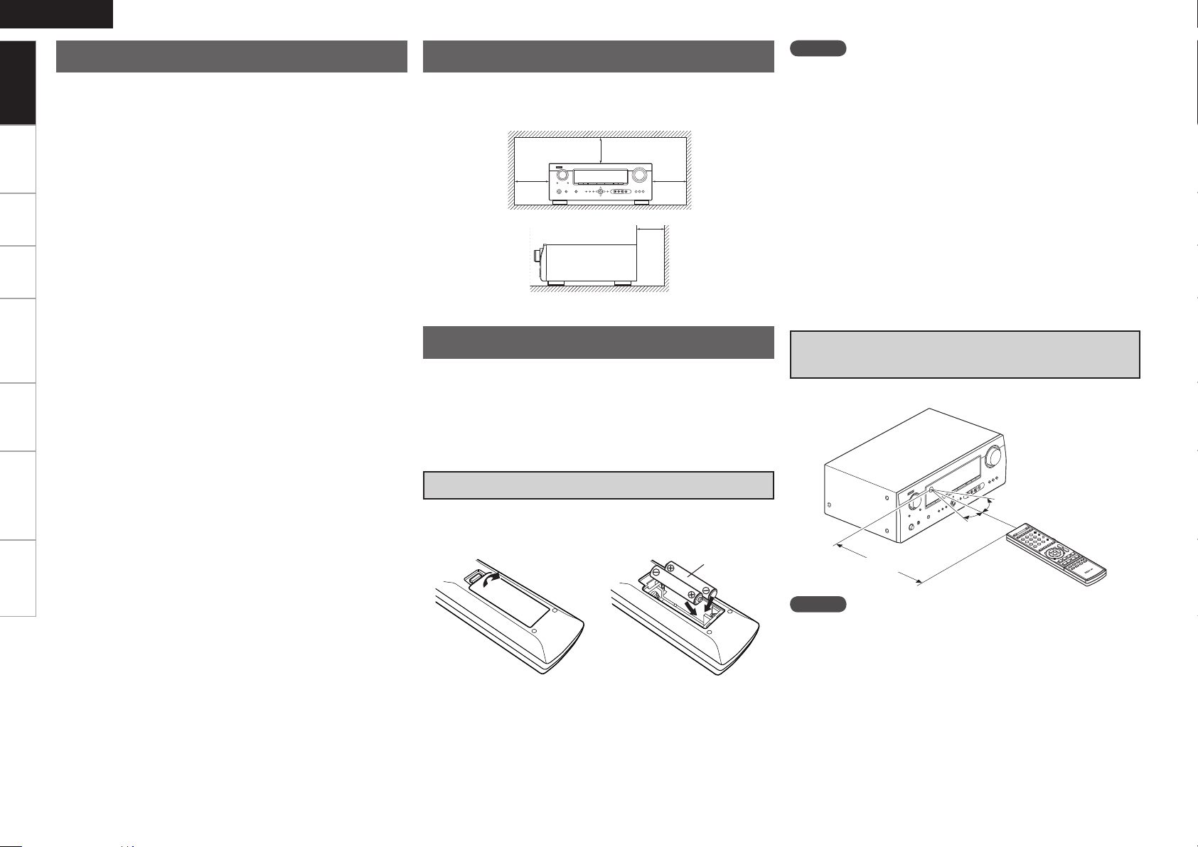
About the Remote Control Unit
In addition to the AVR-590, the included remote control unit (RC-
1120) can also be used to operate the equipment listed below.
q DENON system components
w Non-DENON system components
• By setting the preset memory (vpage 46)
NOTE
• Replace the batteries with new ones if the set does not operate even
when the remote control unit is operated close to the unit.
• The supplied batteries are only for verifying operation.
• When inserting the batteries, be sure to do so in the proper direction,
following the “q” and “w” marks in the battery compartment.
• To prevent damage or leakage of battery fluid:
• Do not use a new battery together with an old one.
• Do not use two different types of batteries.
• Do not attempt to charge dry batteries.
• Do not short-circuit, disassemble, heat or dispose of batteries in
flames.
• If the battery fluid should leak, carefully wipe the fluid off the inside
of the battery compartment and insert new batteries.
• Remove the batteries from the remote control unit if it will not be in
use for long periods.
• Used batteries should be disposed of in accordance with the local
regulations regarding battery disposal.
Operating Range of the Remote Control
Unit
Point the remote control unit at the remote sensor when operating it.
Inserting the Batteries
q Lift the clasp and remove the
rear cover.
e Put the rear cover back on.
w Load the two batteries properly
as indicated by the marks in
the battery compartment.
R03/AAA
Approx. 23 feet / 7 m
NOTE
The set may function improperly or the remote control unit may not
operate if the remote control sensor is exposed to direct sunlight,
strong artificial light from an inverter type fluorescent lamp or infrared
light.
30°
30°
Page 7

Part Names and Functions
q
u
o
Q4
Q7
Q6
e
r
t
y
i
w
Q8
Q3
Q1
Q5
Q0
Q2
q
Q9
Q0 Q1 Q2 Q3 Q4 Q5 Q6 Q7
W0
w e r t y
W1
W2
u
i
W3
W4W5W6
W7
W8
o
E0
Q8
W9
Front Panel
ENGLISH
Getting Started
W5 HD AUDIO indicator ···································· (38)
W6 MASTER VOLUME indicator
W7 Display
W8 Remote control sensor ·································(3)
W9 TUNING PRESET button ···························· (36)
E0 SOURCE MODE SELECT button················(34)
Buttons, connectors and displays only provided on the main unit
Q9 Power indicator ·········································· (16)
W0 Power switch (hON jOFF) ··············· (16, 57)
W1 Headphones jack (PHONES) ······················ (37)
W2 V. AUX INPUT connectors ························· (15)
W3 SETUP MIC jack ··········································(20)
W4 AUDYSSEY DYNAMIC VOLUME
indicator ······················································(42)
Button that function in the same way as remote control buttons
For buttons not explained here, see the page indicated in parentheses ( ).
q Power operation button
(ON/STANDBY) ·········································· (16)
w SURROUND MODE buttons ······················ (37)
e MENU button ·············································· (17)
r Cursor buttons (uio p) ························· (17)
t ENTER button ············································· (17)
y RETURN button ·········································· (17)
u QUICK SELECT buttons ····························· (45)
i MASTER VOLUME control knob ···············(34)
o SOURCE SELECT knob······························· (34)
Q0 VIDEO SELECT button ····························(44)
Q1 SLEEP TIMER button ·······························(44)
Q2 INPUT MODE button ··································(32)
Q3 RESTORER button ······································ (43)
Q4 DYNAMIC EQ button ·································· (42)
Q5 DYNAMIC VOLUME button ······················· (42)
Q6 MULTEQ button ········································· (41)
Q7 DIMMER button ·········································· (37)
Q8 STATUS button ··········································· (43)
n Buttons that function in the same
way as Front Panel buttons
Connections Playback Remote Control Information Troubleshooting
Settings
Specifications
Page 8
ENGLISH
u yioQ0Q1Q2Q3Q4
wq e tr
Getting Started
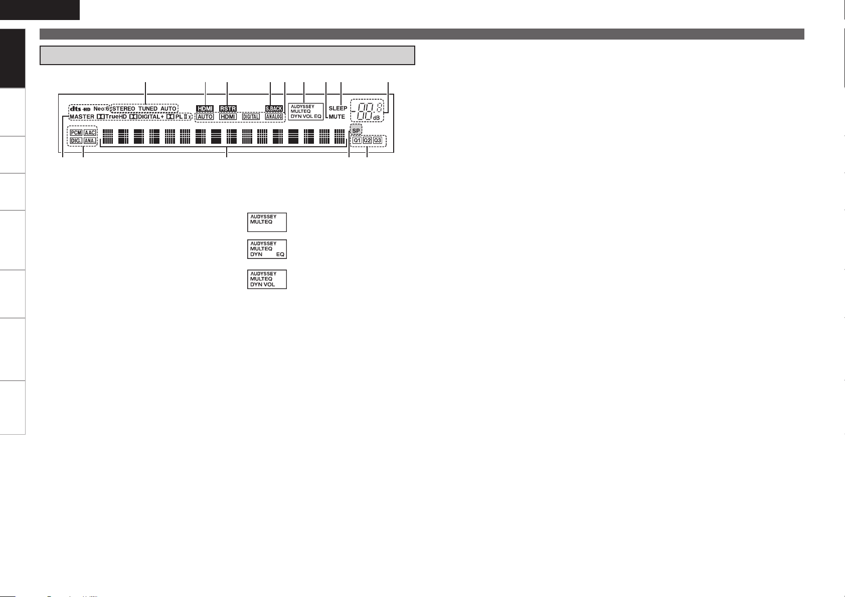
Display
Connections Playback Remote Control Information Troubleshooting Specifications
Settings
Part Names and Functions
q Decoder indicators
The indicator for the currently operating decoder
lights.
w Input audio signal indicators
e Information display
The input source name, surround mode, setting
values and other information are displayed
here.
r Front speaker indicator
Lights when audio signals are being output
from the speakers.
t QUICK SELECT indicators
These light when the Quick Select function is
set (vpage 45).
y Master volume indicator
When performing setting operations, displays
the menu number.
u SLEEP TIMER indicator
Lights when the sleep timer is operating
(vpage 44).
i MUTE indicator
Lights when the muting mode is set (vpage
37).
o AUDYSSEY indicator
These light as shown below in the different
modes (vpage 41).
: During “MultEQ” operation
: During “MultEQ” , “Dynamic EQ”
operation
: During “MultEQ” , “Dynamic EQ”,
“Dynamic Volume” operation
b When speaker settings are changed after the
Audyssey Auto Setup procedure, either the
indicators’ frame turns off or all the indicators
turn off.
Q0 Input mode indicators
Q1 S.BACK indicator
Lights when surround back audio signals are
being output from the SURR. BACK / FRONT
HEIGHT PRE OUT connectors (vpage 25).
Q2 RESTORER indicator
Lights during “RESTORER” operation (vpage
43).
Q3 HDMI indicator
Lights when HDMI input signals are detected
(vpage 13).
Q4 Tuner reception mode indicators
This lights according to the reception conditions
when the input source is set to “TUNER”.
• AUTO
This lights when in the auto tuning mode.
• STEREO
In the FM mode, this lights when receiving
analog stereo broadcasts.
• TUNED
This lights when the broadcast is properly
tuned in.
Page 9
q w e
r
t y u
i
oQ0Q1
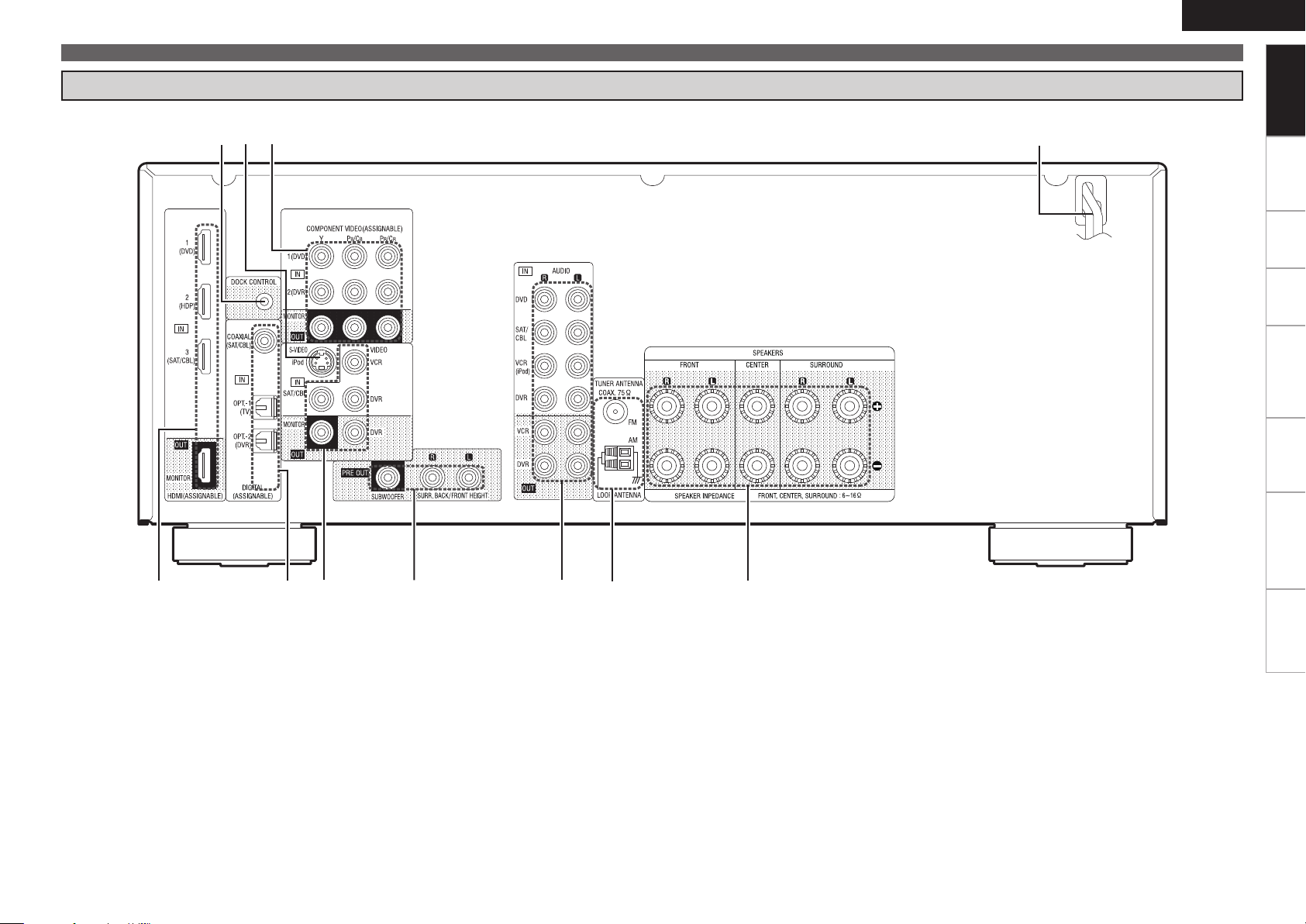
Rear Panel
ENGLISH
Part Names and Functions
Getting Started
Connections Playback Remote Control Information Troubleshooting
q HDMI connectors ·····································································(13)
w Digital audio connectors ·························································(14)
e VIDEO connectors ···································································(15)
r PRE OUT connectors ······························································· (11)
t Analog audio connectors ························································(14)
y FM/AM antenna terminals ······················································ (16)
u Speaker terminals ···································································· (11)
i Power cord ··············································································· (16)
SpecificationsSettings
o COMPONENT VIDEO connectors ···········································(14)
Q0 Control Dock for iPod S-Video input connector ···················(14)
Q1 Control Dock for iPod DOCK CONTROL jack DOCK CONTROL jackDOCK CONTROL jack ·························(14)
Page 10
ENGLISH
q
w
e
r
t
y
u
o
Q0
i
W2
Q1
Q2
W3
Q3
W4
Q4
W5
W6
W7
Q5
Q6
Q7
Q8
Q9
W0
W1
W8
Getting Started
Remote Control Unit
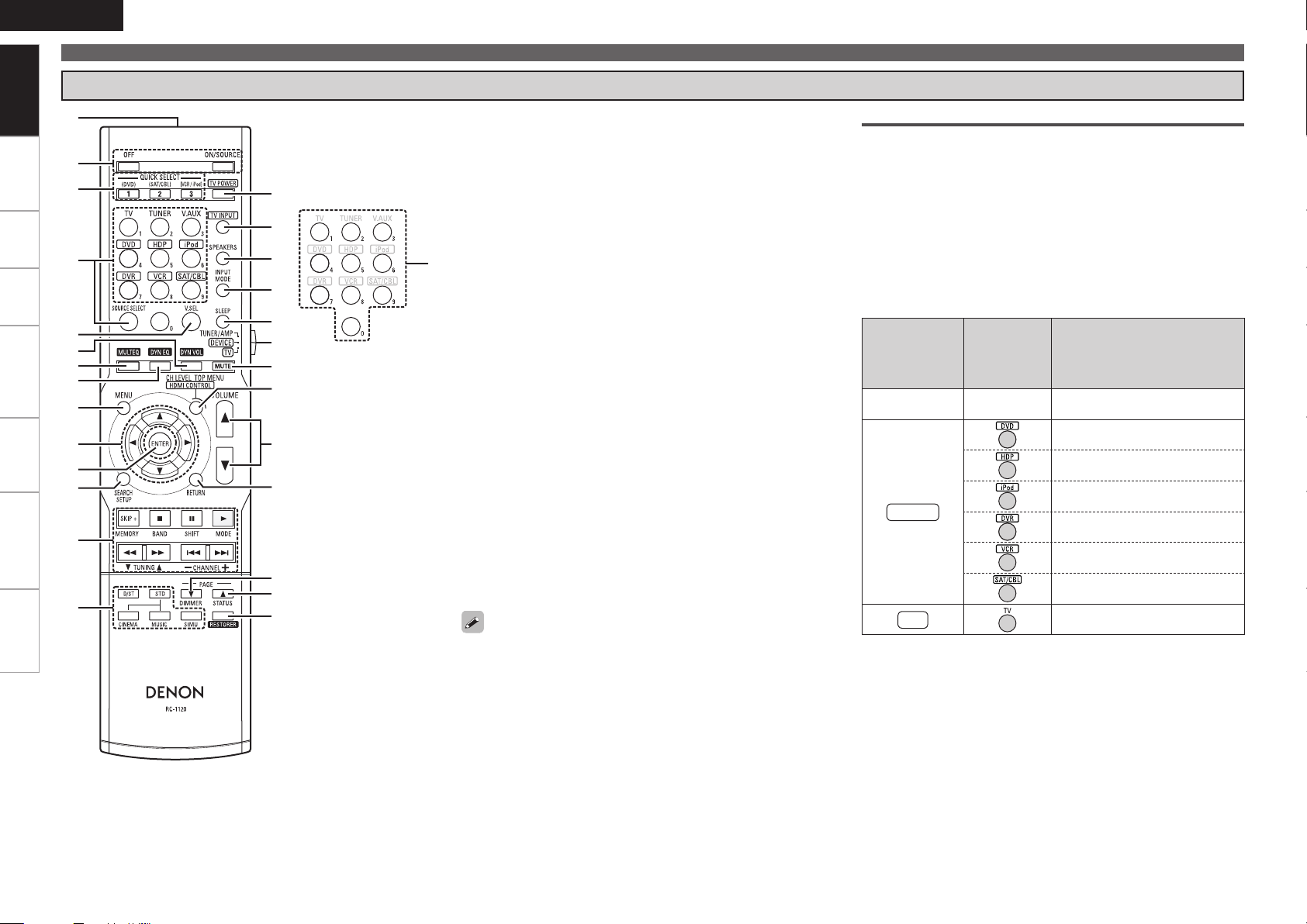
Part Names and Functions
Connections Playback Remote Control Information Troubleshooting SpecificationsSettings
qRemote control signal transmitter
wPower buttons ·········································································(16)
eQUICK SELECT buttons ··························································(45)
rSOURCE SELECT buttons ·······················································(34)
tVIDEO SELECT button ····························································(44)
yDYNAMIC VOLUME button ···················································· (42)
uMULTEQ button ······································································(41)
iDYNAMIC EQ button ·······························································(42)
oMENU button ··········································································· (17)
Q0Cursor buttons (uio p) ······················································(17)
Q1ENTER button ·········································································· (17)
Q2SEARCH button ·······································································(35)
Q3System buttons ·······································································(46)
Q4 Surround mode buttons ·························································(37)
Q5 TV POWER button ··································································· (47)
Q6 TV INPUT button ·····································································(47)
Q7FRONT HEIGHT SPEAKER ON/OFF button ···························(41)
Q8INPUT MODE button ······························································· (32)
Q9SLEEP TIMER button ······························································· (44)
W0Device select switch ··························································(34, 46)
W1MUTING button ······································································· (37)
W2Channel level adjustment button ··········································(45)
W3Master volume control buttons ·············································(34)
W4RETURN button ·······································································(17)
W5DIMMER button ······································································· (37)
W6STATUS button ········································································(43)
W7RESTORER button ··································································· (43)
W8Number buttons (0 ~ 9) ··························································· (46)
For buttons not explained here, see the page indicated in parentheses
( ).
Operations possible by remote control
Operations on the AVR-590
n
Operations on six devices other that the AVR-590
n
Preset the remote control codes of the devices to be operated
beforehand (vpage 46).
qSwitch the DEVICE SELECT switch according to the device to be
operated.
w Press the SOURCE SELECT button for the device to be
operated.
b For detailed operating instructions, see “Operating registered
devices” (vpage 46).
q
DEVICE SELECT
switch
TUNER/AMP
DEVICE
TV
Punch through setting (vpage 48)
n
w
SOURCE
SELECT
button
− AVR-590 and Tuner
Operable devices
DVD Player or CD player
Blu-ray disc player
iPod (DENON)
Digital video recorder
Video deck
Satellite receiver or Cable TV
TV
Page 11

R
L
R
L
Connections
ENGLISH
Getting Started
Connection Flown
Installing/Setting the Speakers (vpage 10)
Connecting the Speakers (vpage 11)
Connecting Devices (vpage 12)
Connecting Devices not Equipped with HDMI
connectors (vpage 13)
n HDMI (vpage 12)
n Monitor (TV) (vpage 13)
n Playback Components
• Blu-ray Disc player / DVD player (vpage 14)
• iPod® (vpage 14)
n SAT/CABLE Tuner (vpage 14)
n Recording Components
• DVD Recorder (vpage 15)
• Video Cassette Recorder (vpage 15)
n Other Devices
• Video Camera / Game Console (vpage 15)
• Antenna terminals (vpage 16)
n Power Cord
Turning the Power On (vpage 16)
Important Information
Connections for all compatible audio and video signal formats
are described in this owner’s manual. Please select the types of
connections suited for the equipment you are connecting.
After connections are completed, certain settings must be made on
the receiver. Make the settings indicated“
for the individual items.
NOTE
• Do not plug in the power cord until all connections have been
completed.
• When making connections, also refer to the operating instructions
of the other components.
• Be sure to connect the left and right channels properly (left with left,
right with right).
• Do not bundle power cords together with connection cables. Doing
so can result in humming or noise.
Set as necessary
Cables Used for Connections
Select the cables according to the equipment being connected.
”
HDMI
connections
Coaxial digital
connections
Optical digital
connections
Analog
connections
Analog
connections
(monaural, for
subwoofer)
Speaker
connections
Component
video
connections
S-Video
connections
Video
connections
Audio and video cables
HDMI cable
Audio cables
Coaxial digital cable
Optical cable
(White)
(Red)
Stereo pin-plug cable
Pin-plug cable
Speaker cables
Video cables
(Green)
(Blue)
(Red)
Component video cable
S-Video cable
(Yellow)
75 Ω/ohms pin-plug video cable
Connections
Playback Remote Control Information Troubleshooting
SpecificationsSettings
Page 12

ENGLISH
MENU
[ENT]:Select
MODE:STEREO
IN :DVD
[Auto]
Master Volume -80.0dB
Getting Started Playback Remote Control Information Troubleshooting Specifications
Important Information
Converting Input video signals for Output
(Video Conversion Function)
Connections
The AVR-590 is equipped with four types of video input connectors (HDMI, Component video, S-Video and
video) and three types of video output connectors (HDMI, Component video and video).
Use the connectors according to the devices to be connected.
This function automatically converts various formats of video signals input to the AVR-590 into the format
used to output the video signals from the AVR-590 to a monitor.
Settings
Video devices
Output
HDMI connector
Component video
connectors
S-Video connector
Input
(IN)
HDMI connector
Component video
connectors
S-Video
connector
AVR-590
Output
(MONITOR OUT)
HDMI
connector
Component video
connectors
Monitor (TV)
HDMI connector
Component video
Input
connectors
How the on-screen display is displayed depending on the
video input signal
The way the on-screen display of the menus, status, etc., is displayed differs according to the type of video
signal input to the AVR-590.
When video signals are input from the HDMI or component video connectors
Menu: Switches to a screen with a black background and the menu is superimposed. (b)
•
Status display: Not displayed.
•
b: If you want to display the menus superimposed on the picture being played, input the same video
signals to the S-Video or video connectors. When a menu is displayed, the picture switches to the one
being input from the S-Video or video connectors and the menu is displayed superimposed over this
picture.
NOTE
Menus and status display screens are not displayed for component video connector pictures. To
display them, also connect the video connectors.
When video signals are being input from the S-Video or video connectors
Menu: Menus are displayed superimposed over the picture being played.
•
Status display: Displayed.
•
Examples of on-screen display
n
Menu screen• Status display screen•
When the input source is
switched
When the volume is adjusted
Video connector
The video conversion function supports the NTSC, PAL, SECAM, NTSC 4.43, PAL-N, PAL-M and PAL-60
formats.
NOTE
• The S-Video input connector is exclusively for use with a Control Dock for iPod. It can be used when the
Control Dock for iPod is connected to the connector assigned to the iPod input source.
• HDMI signals cannot be converted into analog signals.
• When a non-standard video signal from a game machine or some other source is input, the video
conversion function might not operate.
Video connector
Video connector
Video connector
Status display: The operating status is displayed temporarily on the
screen when the input source is switched or the
volume is adjusted.
Page 13

Installing/Setting the Speakers
z
1
z4
z
5
z
2
z
3
z
1
z
2
z3
z
1
z
2
z4
z
2
z
1
z
3
ENGLISH
Getting Started
• The AVR-590 is compatible with various types of
surround playback.
• Decide on the surround modes to be played on
the AVR-590 before making connections and
settings.
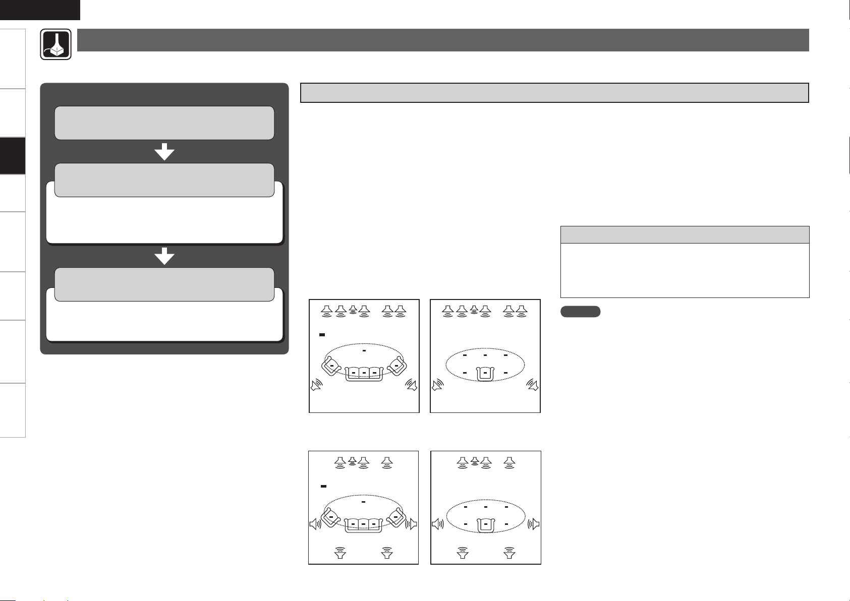
a Determine the Speaker Layout.
Below we introduce examples of speaker layouts. Refer
to these to arrange your speakers according to their
type and how you want to use them.
Installing All the Speakers
Front Height speakers
Front
speakers
Subwoofer
Surround
speaker
Surround back speakers
NOTE
• It is not possible to use the front height speakers and
surround back speakers simultaneously.
• To play surround back speakers or front height speakers,
connect a power amplifier to the AVR-590’s SURR. BACK /
FRONT HEIGHT PRE OUT connectors (vpage 11).
Center
speaker
Surround
speaker
When 7.1ch (Surround Back Speaker) Connectedn
Front speakers
Center speaker
Monitor
z1: 22 ~ 30˚
z2: 90˚
z4: 30˚
z5: 45˚
When 5.1ch Connectedn
Front speakers
Center speaker
Monitor
z1: 22 ~ 30˚
z2: 120˚
Connections
z3: 110˚
Subwoofer
Surround speakers
Surround back
speakers
As seen from above
G
Surround
speaker
Front
speaker
H
As seen from the side
G
Surround back
speaker
2 to 3 feet /
60 to 90 cm
Point slightly
downwards
H
When 6.1ch Connectedn
Front speakers
Center speaker
Monitor
Subwoofer
Surround speakers
Surround back
As seen from above
G
speaker
H G
z1: 22 ~ 30˚
z2: 90˚
z3: 110˚
Surround
speaker
Front
speaker
2 to 3 feet /
60 to 90 cm
As seen from the side
Surround back
speaker
Point slightly
downwards
H
Subwoofer
Surround
speaker
2 to 3 feet /
60 to 90 cm
As seen from the side
Playback Remote Control Information Troubleshooting
H
Surround speakers
As seen from above
G
Front
speaker
H G
When 7.1ch (Front Height Speaker) Connectedn
Front height speakers
Front speakers
Center speaker
Subwoofer
As seen from above
G
Monitor
Surround speakers
z1: 30˚
z2: 45˚
Point slightly
downwards
Front speaker
H
z3: 90˚
z4: 110˚
Front height
speaker
As seen from the side
G
Surround
speaker
2 to 3 feet /
60 to 90 cm
SpecificationsSettings
H
0
Page 14

ENGLISH
R
L
R
L
w qw q
(R) (L)
w q
*/
w q w q
(L) (R)
w q
(R)
w q
(L)
Getting Started Playback Remote Control Information Troubleshooting Specifications
s
Set the “Pre Assign” Mode According to the Speaker Layout.
The signals output from the AVR-590’s SURR. BACK / FRONT HEIGHT PRE OUT connectors can be
switched to signals of the surround mode being used (vpage 24 “Pre Assign”).
Connections
The speaker which plays the a
Pre Assign mode
(vpage 24)
Settings
sound output from the SURR.
BACK / FRONT HEIGHT PRE
OUT connectors
Installing/Setting the Speakers
Example of speaker installation
Connecting the Speakers
Subwoofer with
builtin amplifier
Front
speakers
Center
speaker
Surround
speakers
Normal
(Default)
Normal
Normal
Front Height
Surround back
speakers
Surround back
speakers
b Connect to the SURR. BACK /
FRONT HEIGHT PRE OUT “L”
connector.
25) to “1ch”.
b Set “S.Back (Pre out)” (vpage
Not connected
b Set the “S.Back (Pre out)” settingS.Back (Pre out)” setting” setting
(vpage 25) to “None”.
Front Height
speakers
(7.1)
(6.1)
(5.1)
(7.1)
Power amplifier
Front Height
speakers
To play surround back speakers or front height speakers,
connect a power amplifier to the AVR-590’s SURR. BACK /
FRONT HEIGHT PRE OUT connectors.
Make the “Pre Assign” (vpage 24) settings.
Surround back
or
speakers
Page 15
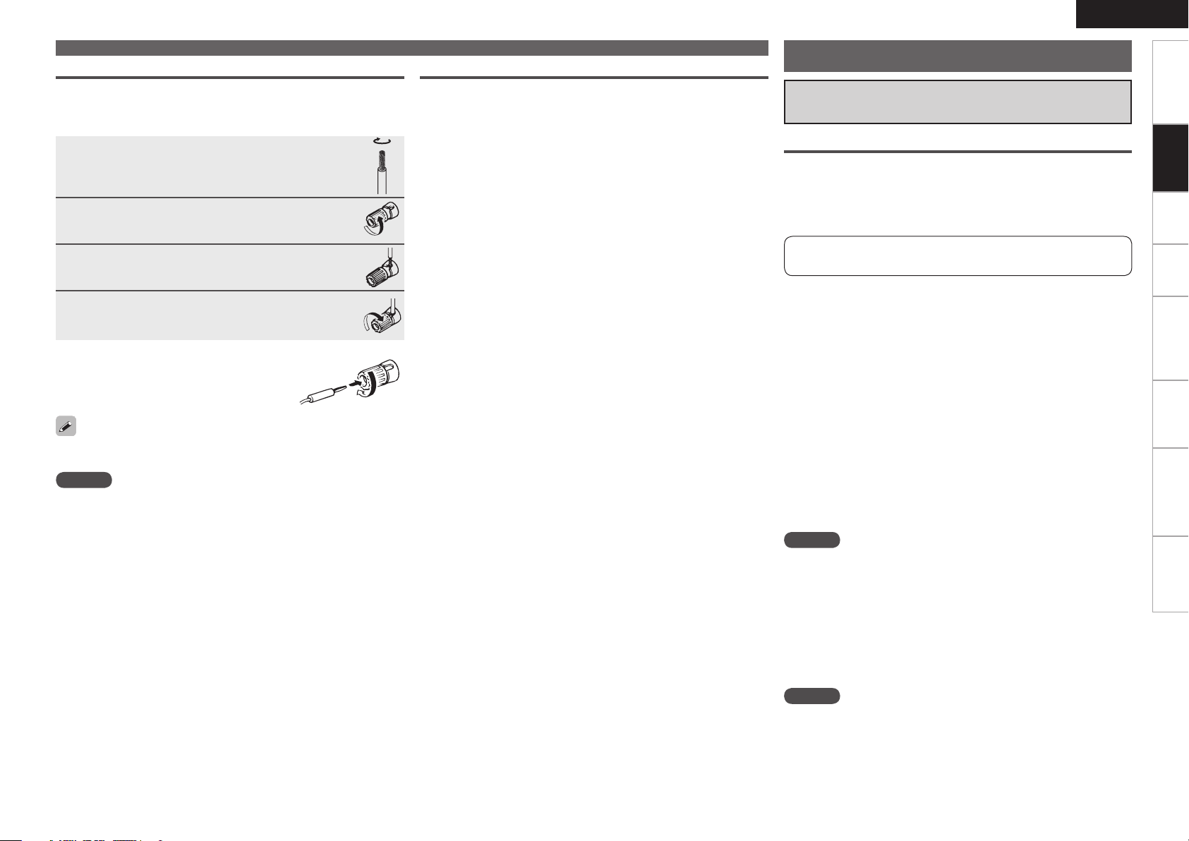
Connecting the Speaker Cables
Carefully check the left (L) and right (R) channels and + (red) and –
(black) polarities on the speakers being connected to the AVR-590, and
be sure to interconnect the channels and polarities correctly.
Peel off about 10 mm of sheathing from the tip
1
of the speaker cable, then either twist the core
wire tightly or terminate it.
Turn the speaker terminal counterclockwise
2
to loosen it.
Insert the speaker cable’s core wire to the hilt
3
into the speaker terminal.
Turn the speaker terminal clockwise to tighten
4
it.
n When using a banana plug
Tighten the speaker terminal firmly before
inserting the banana plug.
Use speakers with an impedance of 6 to 16 Ω/ohms.
NOTE
• Connect the speaker cables in such a way that they do not stick out
of the speaker terminals. The protection circuit may be activated if
the core wires touch the rear panel or if the + and – sides touch each
other (v “Protection circuit”).
• Never touch the speaker terminals while the power
supply is connected. Doing so could result in electric shock.
Connecting the Speakers
Protection circuit
If the core wires touch the rear panel and the screws etc., or the ±
sides touch each other, the protection circuit will be activated and the
power indicator will flash red at intervals of 0.5 secs.
If the protection circuit is activated, the speaker output is isolated, and
the power supply goes to the standby state. If the power supply is
turned off, after the power supply cord is withdrawn, please confirm
that speaker cable and input cable are connected.
Also, if replaying large sound levels by using a speaker having an
impedance less than that specified (eg, 4 Ω/ohms), the temperature
will rise, and the protection circuit might be activated. The power
supply will go into the standby state, and the power indicator will flash
red at 2 second intervals.
In this case, please switch off the power supply, and wait until the
AVR-590 has cooled down, and the surrounding ventilation is good.
Even if there are no problems with the surrounding ventilation
and connections, in the event of the protection circuit becoming
activated,
due to thinking that the AVR-590 has failed, please contact DENON
Service center after switching off.
ENGLISH
Connecting Devices
Connecting Devices Equipped with
HDMI connectors
Important Information
n About HDMI
“HDMI” is the abbreviation of “High Definition Multimedia
Interface”. This interface allows transfer of digital video signals
and digital audio signals over a single HDMI cable.
“HDMI”, “HDMI logo” and “High-Definition Multimedia Interface”
are trademarks or registered trademarks of HDMI Licensing LLC.
n Functions usable with HDMI connections
Deep Color
Eliminates on-screen color banding, for smooth tonal transitions and
subtle gradations between colors.
x.v.Color
Enables displays with natural, vivid colors. “x.v.Color” is a Sony
registered trademark.
Auto Lip Sync (vpage 27)
HDMI 1.3 incorporates an automatic video/audio synching capability
that allows devices to perform this synchronization automatically with
total accuracy.
HDMI control function (vpage 27, 44)
This function allows you to operate external devices from the receiver
and operate the receiver from external devices.
NOTE
These functions will not work if the device connected to the HDMI
connector does not support Deep Color or x.v.Color signal transfer or
the Auto Lip Sync function.
Getting Started
Connections
Playback Remote Control Information Troubleshooting
SpecificationsSettings
n Copyright protection system (HDCP)
The AVR-590 supports HDCP (High-bandwidth Digital Contents
Protection). HDCP is a copyright protection technology for digital video
signals. The devices connected to the AVR-590 must also support
HDCP.
NOTE
When a device that does not support HDCP is connected, video
signals are not properly output.
Page 16
ENGLISH
*/
7*%&0
$0.10/&/57*%&0
: 1# 13
7*%&0
*/
"6%*0
015*$"-
065
065
)%.*
065
)%.*
065
)%.*
*/
)%.*
Getting Started Playback Remote Control Information Troubleshooting SpecificationsSettings
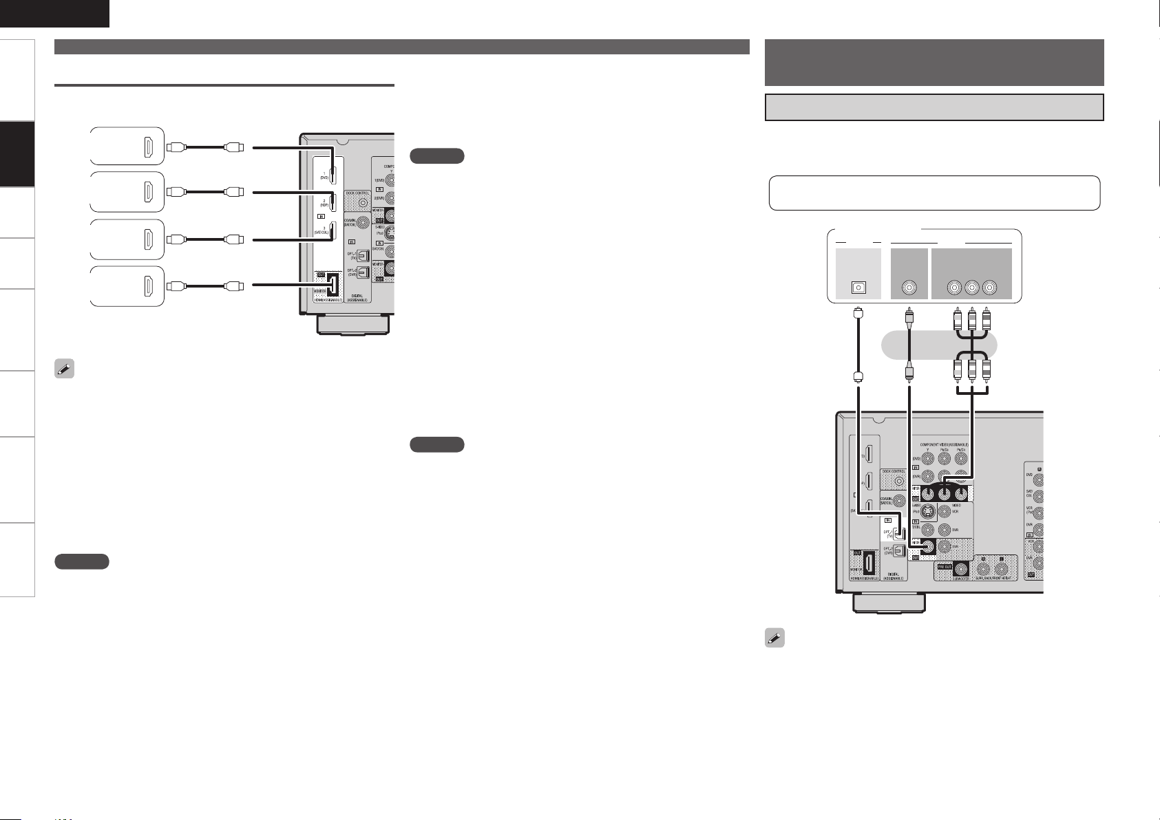
Connections
The AVR-590 allows connection of inputs from up to 3 HDMI
devices and output to 1 TV.
Connections
DVD
Player
Blu-ray
Disc Player
SAT/CABLE
Tuner
Connecting devices
n Connecting to a device equipped with a DVI-D
connector
When an HDMI/DVI conversion cable (sold separately) is used, the
HDMI video signals are converted to DVI signals, allowing connection
to a device equipped with a DVI-D connector.
NOTE
• No sound is output when connected to a device equipped with a
DVI-D connector. Also make the audio connections.
• Signals cannot be output to DVI-D devices that do not support
HDCP.
• Depending on the combination of devices, the video signals may not
be output.
Connecting Devices not
Equipped with HDMI connectors
Monitor (TV)
• Select the terminal to use and connect the device.
• For video connections, see “Converting input video signals for output
(Video Conversion Function)” (vpage 9).
For instructions on HDMI connections, see “Connecting Devices
Equipped with HDMI connectors” on page 12.
Monitor (TV)
Monitor
(TV)
• Use a cable on which the HDMI logo is indicated (a certified HDMI
product) for connection to the HDMI connector. Normal playback
may not be possible when using a cable other than one on which the
HDMI logo is indicated (a non-HDMI-certified product).
• When the AVR-590 is connected to other devices with HDMI cables,
also connect the AVR-590 and TV using an HDMI cable.
• When a device supporting Deep Color signal transfer is connected,
use a cable compatible with HDMI ver.1.3a.
• Video signals are not output if the input video signals do not match
the monitor’s resolution. In this case, switch the Blu-ray Disc player /
DVD player’s resolution to a resolution with which the monitor is
compatible.
NOTE
• If the menu “HDMI Audio Out” setting (vpage 27) is set to “AMP”,
the sound may be interrupted when the monitor’s power is turned
off.
• The audio signal from the HDMI output connector (sampling
frequency, number of channels, etc.) may be limited by the HDMI
audio specifications of the connected device regarding permissible
inputs.
n Settings related to HDMI connections
Set as necessary. For details, see the respective reference pages.
Input connector assignment (vpage 31)
Set this when changing the input sources of the different connectors.
HDMI Setup (vpage 27)
Make these settings related to HDMI input/output signals.
• Auto Lip Sync
• HDMI Audio Out
• HDMI Control
• Standby Source
• Power Off Control
NOTE
The audio signals output from the HDMI connectors are only the
HDMI input signals.
The component video connectors may be indicated differently on your
monitor. For details, see the monitor’s operating instructions.
Page 17
ENGLISH
R
L
R
L
ASD-3Nまたは
ASD-3W
R
L
R
L
7*%&0
$0.10/&/57*%&0
: 1# 13
065
"6%*0
"6%*0
3-
065
065
"6%*0 7*%&0
7*%&0"6%*0
3-
065 065
$0"9*"-
R
L
R
L
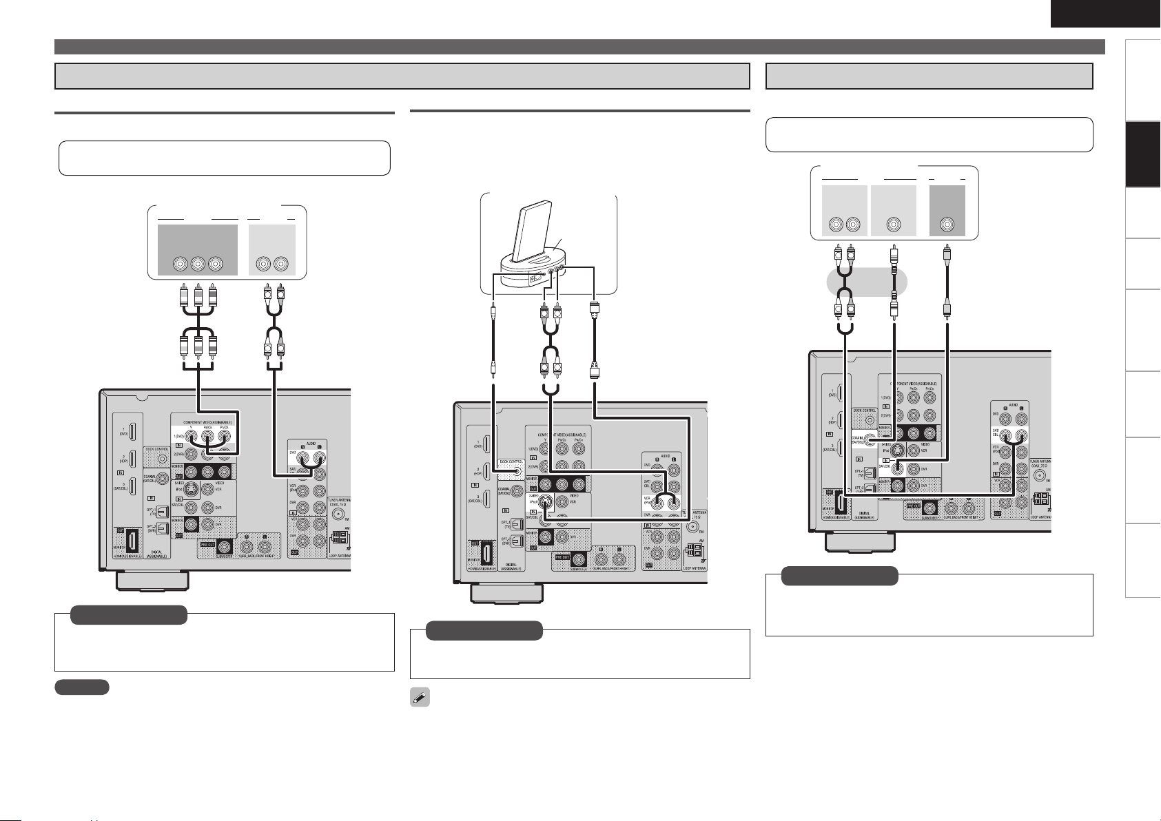
Connecting Devices not Equipped with HDMI connectors
Getting Started
Playback Components
Blu-ray Disc player / DVD player
Select the terminal to use and connect the device.
For instructions on HDMI connections, see “Connecting Devices
Equipped with HDMI connectors” on page 12.
Blu-ray Disc player /
DVD player
Control dock for iPod
®
Use a DENON control dock for iPod (ASD-1R, ASD-11R, ASD-3N or
ASD-3W sold separately) to connect the iPod to the AVR-590. For
instructions on the control dock for iPod settings, refer to the control
dock for iPod’s operating instructions.
Control dock for iPod
ASD-3N or
ASD-3W
SAT/CABLE Tuner
Select the terminal to use and connect the device.
For instructions on HDMI connections, see “Connecting Devices
Equipped with HDMI connectors” on page 12.
SAT/CABLE Tuner
Connections
Playback Remote Control Information Troubleshooting
Set as necessary
Set this to change the input signal to which the input source
is assigned.
“Assign” (vpage 31)
NOTE
When connected to a Blu-ray Disc player, and playing Dolby TrueHD,
DTS-HD, Dolby Digital Plus, connect the HDMI.
Set as necessary
Set this to assign the iPod to a connector other than “VCR
(iPod)” “iPod Dock” (vpage 31)
With the default settings, the iPod can be used connected to the VCR
(iPod) connector.
SpecificationsSettings
Set as necessary
Set this to change the input signal to which the input source
is assigned.
“Assign” (vpage 31)
Page 18

ENGLISH
R
L
R
L
065
"6%*0 7*%&0
7*%&0"6%*0
3-
065
3-
065065
"6%*0"6%*0 7*%&0
"6%*0
3-
*/
"6%*0
7*%&0
R
L
R
L
R
L
R
L
R
L
R
L
R
L
R
L
3- 3-
065
*/
"6%*0
"6%*0 7*%&07*%&0
065
015*$"-
*/
"6%*0"6%*0
065
7*%&0 7*%&0
$0.10/&/57*%&0
: 1# 13
065
Getting Started Playback Remote Control Information Troubleshooting SpecificationsSettings
Connecting Devices not Equipped with HDMI connectors
Recording Components
Digital Video Recorder
Connections
Select the terminal to use and connect the device.
For instructions on HDMI connections, see “Connecting Devices
Equipped with HDMI connectors” on page 12.
DVD Recorder
Other Devices
Video Cassette Recorder
Select the terminal to use and connect the device.
For instructions on HDMI connections, see “Connecting
Devices Equipped with HDMI connectors” on page 12.
Video cassette recorder
Video Camera / Game Console
Video camera /
Game console
Set as necessary
Set this to change the input signal to which the input source
is assigned.
“Assign” (vpage 31)
NOTE
To record video signals through the AVR-590, use the same type of
video cable for connection between the AVR-590 and the player as the
cable used for connection between the AVR-590 and the recorder.
Set as necessary
Set this to change the input signal to which the input
source is assigned.
“Assign” (vpage 31)
NOTE
To record video signals through the AVR-590, use the same type
of video cable for connection between the AVR-590 and the
player as the cable used for connection between the AVR-590
and the recorder.
Page 19

Antenna terminals
Direction of broadcasting station
FM antenna
75 Ω/ohms
Coaxial cable
FM indoor antenna
(supplied)
WhiteBlack
Ground
n AM loop antenna assembly
1
AM outdoor antenna
Remove the vinyl tie and take out the
connection line.
Bend in the reverse direction.
2
With the antenna on top of any
-1
3
stable surface.
Mount
With the antenna attached to a
-2
3
wall.
AM loop
antenna
(supplied)
Connecting Devices not Equipped with HDMI connectors
n Connection of AM antennas
Push the lever.
1
Insert the conductor.
2
Return the lever.
3
NOTE
• Do not connect two FM antennas simultaneously.
• Even if an external AM antenna is used, do not disconnect the AM
loop antenna.
• Make sure the AM loop antenna lead terminals do not touch metal
parts of the panel.
Connecting the Power Cord
Wait until all connections have been completed before connecting the
power cord.
To household
power outlet
(AC 120 V, 60 Hz)
Power cord
ENGLISH
Once Connections are
Completed
Turning the Power On
Press .
The power indicator lights red and the
1
power is set to the standby mode.
Press .
The power indicator flashes green and the
2
power turns on.
b Also press when in
standby mode, the power turns on.
When has been pressed, the input
source set with the is set.
If a has been pressed, the input source stored
in the memory for the quick select function is set (vpage 45
“Saving frequently used settings (Quick Select Function)”).
This operation can also be performed by
pressing a on the main unit.
Turning the Power Off
Press .
The power is set to the standby mode.
1
Getting Started
Connections
Playback Remote Control Information Troubleshooting
SpecificationsSettings
Installation hole Mount on wall, etc.
NOTE
Insert the AC plugs securely. Incomplete connections could cause
noise.
Press .
The power indicator turns off, and so does
2
the power.
NOTE
Power continues to be supplied to some of the circuitry even when
the power is in the standby mode. When leaving home for long periods
of time or when traveling, either press to turn off the power, or
unplug the power cord from the power outlet.
Page 20

ENGLISH
MENU
1.Parameter
2.Information
3.Auto Setup
4.Manual Setup
5.Input Setup
[ENT]:Select
Getting Started Connections Playback Remote Control Information Troubleshooting Specifications
Settings
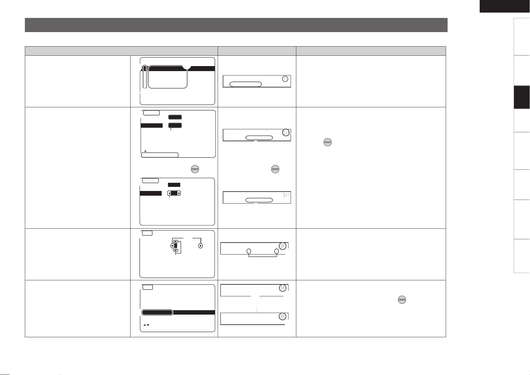
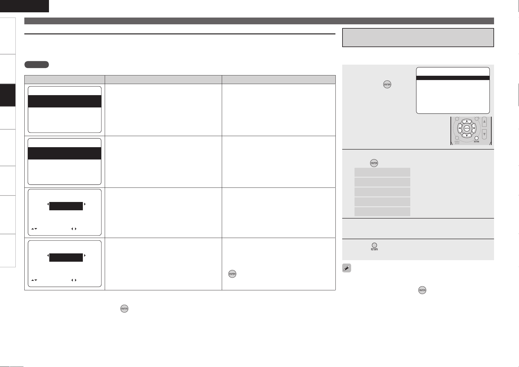
With the AVR-590, settings and operations for most functions can be performed by operating while looking at the menus displayed on the monitor screen.
Menu map
Settings
nOperations
Press .
1
The menu is
displayed.
Press ui to
2
select the item
you want to
⇩
set, then press
Press ui to
3
select the item
you want to
⇩
set, then press
.
.
Use uiop to select the item,
4
then press to set.
b To return to the previous item, press .
⇩
b Select “Default Yes”, then press
reset to the default setting.
to
Press .
5
⇩
The settings made up to that
point are entered and the
settings menu screen turns off.
Setting menusn
Items that only need to be set once
Set these for example upon purchase.
Once these items are set, there is no need to
set them again unless the speaker layout or the
connected speakers have been changed.
Setting items Number Detailed items Description Page
1. Parameter
Adjust various audio parameters.
2. Information
Show information about receiver
settings, input signals, etc.
3. Auto Setup
Makes the optimum speaker
settings and corrects for the
acoustic characteristics of the
room.
4. Manual Setup
Use this to make various types of
detailed settings.
5. Input Setup
Use this to make settings related
to playing input sources.
1-1 Surround Parameter Adjust surround sound parameters. 39
1-2 Tone Control Adjusts the treble and bass tone. 41
1-3 Audyssey Settings Makes the MultEQ, Dynamic EQ and Dynamic Volume settings. 41
1-4 Manual EQ Adjust tonal quality for each speaker using graphic equalizer. 42
1-5 RESTORER
1-6 Audio Delay Compensate for incorrect timing between video and audio. 43
2-1 Status Shows information about current settings. 43
2-2 Audio Input Signal Shows information about audio input signals. 43
2-3 HDMI Information Displays the HDMI input/output signals and TV information. 43
2-4 Auto Surround Mode Displays the settings stored for the auto surround mode. 43
2-5 Quick Select Displays the settings stored for the Quick Select function. 43
2-6 Preset Channel Shows information about preset channels. 43
3-1 Audyssey Auto Setup Makes the optimum settings for the speakers being used
3-2 Parameter Check Check Audyssey Auto Setup measurement results.
4-1 Speaker Setup Sets the speaker size and distance, the channel level, etc. 24
4-2 HDMI Setup Make settings for HDMI video/audio output. 27
4-3 Audio Setup Make settings for audio playback. 28
4-4 Option Setup Make various other settings. 28
5-1 Assign Change input connector assignment. 31
5-2 Input Mode Sets the audio input mode and decode mode. 32
5-3 Rename Change the display name for this source. 32
5-4 Source Level Adjust the playback level of the audio input. 33
5-5 iPod Playback Mode Make settings for iPod playback. 33
5-1 Auto Preset Use the auto preset function to program radio stations. 33
5-2 Preset Skip
5-3 Preset Name Assign name to a preset memory. 33
Uncompress compressed sources and apply bass boost for richer sound.
automatically.
This item is only displayed after the Audyssey Auto Setup procedure
has been performed.
Set the preset memories that you do not want to display when tuning.
43
20
23
33
Page 21
Examples of On-screen Display and Front Display
MENU
1.Parameter
2.Information
3.Auto Setup
4.Manual Setup
5.Input Setup
[ENT]:Select
q
w
e
P a r a m e t e r
w
e
5-1-1.Input Assign
HDMI Digi Comp
DVD 1 1
HDP 2
TV 01
SAT/CBL 3 C1
VCR/iPod
DVR 02 2
[ENT]:Select [RTN]:Back
w
q
e
D V D [ H D M I 1 ]
w
q
5-1-1.Input Assign
HDMI Digi Comp
DVD 1 1
HDP 2
TV 01
SAT/CBL 3 C1
VCR/iPod
DVR 02 2
[ENT]:Select [RTN]:Back
q
r
D V D • H D M I 1 –
r
Default
[SRCH]:Caps.
[ENT]:OK [RTN]:Cancel
:
DVD DVD
5-3.Rename
w
e
q
q
e
D V D • ¡ D V D –
[ ]:Up/Down
[ENT]:Select [RTN]:Back
Default
:
DVD [ DVD ]
5-3.Rename
q
w
q
w
D e f a u l t
D ef a u l t ? : • N o
w
Below we describe typical examples of displays on the TV screen and on the set’s display window.
ENGLISH
Getting Started
On-screen Display Front Display Description
n Top menu display
n Display when changing settings
n Display when inputting characters
Press . Press .
⇩ ⇩
q
: The menu items are displayed here.
w
: The selected line is displayed here.
The currently selected item is displayed on the display.
Use ui to move to the item you want to set.
e
: The number of the current selected setting menu is
displayed.
q
: The number of the current selected setting menu is
displayed.
w
e
r
q
w
e
uio p
: Use
: Press to set to the mode in which the setting can be
made.
: 0 1 is displayed at the sides of items whose setting can be
changed. Use op to change to the desired setting.
: When op is pressed, the cursor moves to the left or right.
: When ui is pressed at the position at which you want to
input the character, the character is input.
: The number of the current selected setting menu is
displayed.
to move to the item you want to set.
Connections Playback Remote Control Information Troubleshooting
Settings
Specifications
n Display when resetting
q
: Press i to select “Default”, then press to set.
w
: The number of the current selected setting menu is
displayed.
Page 22
ENGLISH
FHL FL SW C FR FHR
SL SR
*
M
FHL FL SW C FR FHR
SL SR
*
M
FL SW C FR
SL SR
SBRSBL
*
M
FL SW C FR
SL SR
SBRSBL
*
M
Getting Started Connections Playback Remote Control Information Troubleshooting Specifications
Making the Optimum Settings for the Connected Speakers Automatically (Audyssey Auto Setup)
The acoustic characteristics of the connected speakers and listening room are measured and the optimum settings are made automatically.
Settings
Audyssey Auto Setup Flown
Step 1 :Connect the included Setup
Microphone (vpage 20)
Step 2 :Audyssey Auto Setup Preparations
(vpage 21)
n Changing the PRE OUT connectors assignment
(Pre Assign) (vpage 21)
Step 3 : Performing the Audyssey Auto Setup
Procedure (vpage 21)
n Check Audyssey Auto Setup Measurement
Results (Parameter Check) (vpage 23)
Important Information
Audyssey MultEQ® automatically measures the acoustical
problems in the listening environment to create the best audio
experience for your home theater.
• When the Audyssey Auto Setup procedure is performed, the
MultEQ, Dynamic EQ and Dynamic Volume functions (vpage 41)
are enabled.
• Use the included setup microphone (DM-A409) to perform the
Audyssey Auto Setup procedure.
• Measurements are performed by placing the calibrated microphone
successively at multiple positions throughout the listening area as
shown in GExample qH. For best results, it is strongly recommended
to measure 6 positions so that the measurements have the proper
spatial weighting.
Even if the listening environment is small as shown in GExample wH,
measuring at multiple points throughout the listening environment
results in more effective correction.
n When using Front Height Speakers
GExample qH GExample wH
( : Measuring positions)
n When using Surround Back Speakers
GExample qH GExample wH
FHL : Front height speaker (L)
FL : Front speaker (L)
SW : Subwoofer
C : Center speaker
FR : Front speaker (R)
FHR : Front height speaker (R)
SR : Surround speaker (R)
SBR : Surround back speaker (R)
SBL : Surround back speaker (L)
SL : Surround speaker (L)
About the main listening position (*M)
The main listening position refers to the most central position where
one would normally sit within the listening environment.
MultEQ uses the measurements from this position to calculate
speaker distance, level, polarity, and the optimum crossover value
for the subwoofer.
NOTE
• Loud test sounds may be played during Audyssey MultEQ automatic
speaker setup. This is part of normal operation. If there is background
noise in room, these test signals will increase in volume.
• Do not stand between the speakers and setup microphone or allow
obstacles in the path while the measurements are being made. This
will cause inaccurate readings.
• Make the room as quiet as possible. Background noise can disrupt
the room measurements. Close windows, silence cell phones,
televisions, radios, air conditioners, fluorescent lights, home
appliances, light dimmers, or other devices as measurements may
be affected by these sounds.
Cell phones should be placed away from all audio electronics during
the measurement process as Radio Frequency Interference (RFI)
may cause measurement disruptions (even if the cell phone is not in
use).
( : Measuring positions)
Page 23

Step 1 : Connect the included Setup Microphone
ENGLISH
Making the Optimum Settings for the Connected Speakers Automatically (Audyssey Auto Setup)
Getting Started
NOTE
• Do not disconnect the setup microphone until the Audyssey Auto
Setup procedure is completed.
• When using headphones, unplug the headphones before starting
the Audyssey Auto Setup procedure.
Check the speaker connections.
1
(vpage 11 “Connecting the Speakers”)
Turn on the power of the TV and subwoofer.
2
Set the TV’s input to the AVR-590.
Turn on the AVR-590’s power.
3
(vpage 16 “Turning the Power On”)
Connect the included calibrated setup microphone to
4
the SETUP MIC jack on the main unit.
The Audyssey Auto Setup screen appears automatically.
Sound
receptor
Mount the setup microphone on a tripod or stand and
5
install it at the main listening position.
When installing the setup microphone, adjust its height so that
the section where the sound is received is at the height of the
ears during listening.
NOTE
• Do not hold the microphone in your hand during measurements.
• Avoid placing the microphone close to a seat back or wall as sound
reflections may give inaccurate results.
When using a subwoofer on which the volume can
be adjusted and the crossover frequency can be set
When using a subwoofer, make the following settings before starting
the Audyssey Auto Setup procedure:
n When using a subwoofer with a direct mode
Set the direct mode to “On” and disable the volume adjustment
and crossover frequency setting.
n When using a subwoofer without a direct mode
Make the following settings:
• Volume :“12 o’clock position”
• Crossover frequency :“Maximum/Highest Frequency”
• Low pass filter :“Off”
• Standby mode :“Off”
Connections Playback Remote Control Information Troubleshooting
Settings
Specifications
Setup
microphone
0
Page 24

ENGLISH
Step2:Measurement
MultEQ
Retry
Cancel
[ENT]:Cancel
Calculate
All the measurements
were finished.
Step3:Calculating
MultEQ
Calculating
[----------]
Please wait...
Step4:Check
MultEQ
Please check the results
of the measured item.
Distance Check
Channel Level Check
Crossover Freq.Check
Speaker Config.Check
Next
[ENT]:Select
3-1.Audyssey Auto Setup
MultEQ
at ear height at
Normal
Pre Assign:
Start
Cancel
[ENT]:Select [RTN]:Back
Please place microphone
main listening position.
Next
Retry
[ENT]:Next
Front Sp. :Yes
Center Sp. :Yes
Subwoofer :Yes
Surround Sp. :Yes
S.Back Sp. :Yes
:2sp
Step1:Speaker Detection
MultEQ
Step2:Measurement
MultEQ
Please place microphone
Cancel
[ENT]:Next
Next
Calculate
2nd listening position.
at ear height at
3-1.Audyssey Auto Setup
MultEQ
at ear height at
Normal
Pre Assign:
Start
Cancel
[ENT]:Select [RTN]:Back
Please place microphone
main listening position.
3-1.Audyssey Auto Setup
MultEQ
at ear height at
Normal
Pre Assign:
Start
Cancel
[ENT]:Select [RTN]:Back
Please place microphone
main listening position.
Getting Started Connections Playback Remote Control Information Troubleshooting Specifications
Making the Optimum Settings for the Connected Speakers Automatically (Audyssey Auto Setup)
Step 2 : Audyssey Auto Setup
Preparations
around items indicate the settings made upon purchase.
If adjustment to the environment is necessary, set the following
items before proceeding.
Changing the PRE OUT connectors assignment
Settings
(Pre Assign)
The signals output from the AVR-590’s SURR. BACK / FRONT HEIGHT
PRE OUT connectors can be switched to signals of the surround mode
being used.
Press ui to select “Pre Assign”.
1
Press o p to select
2
Pre Assign Mode.
Normal
Front Height
n To cancel Audyssey Auto Setup
Use ui to select “Cancel”, then use o p to select “Yes”.
: The sound of the surround back channel is output
from the SURR. BACK / FRONT HEIGHT PRE
OUT connectors.
: The sound of the front height channel is output
from the SURR. BACK / FRONT HEIGHT PRE
OUT connectors.
Step 3 : Performing the Audyssey Auto Setup Procedure
• The Audyssey Auto Setup function detects the presence of each
speaker and automatically calculates the speaker size, channel
level, distance, and optimal crossover frequency setting. Audyssey
MultEQ corrects acoustical distortions within the listening area.
• Once started, MultEQ will play a series of test tones through each
speaker.
• Before starting, connect and position all of your speakers.
Press ui to select
1
“Start”, then press
.
Detection of the speaker
configuration starts.
Once all the speakers
2
have been detected
and the screen on
the right appears,
check the results
of detection of the
connected speakers.
Once you have checked the results, use ui to select
3
“Next”, then press .
Measurements for the main listening position begin.
Once the screen on
4
the right appears,
move the setup
microphone to the
second position, use
ui to select “Next”,
then press .
Measurements for the second position begin.
Perform Step 4 repeatedly for the 3rd, 4th, 5th, and
5
6th measurments.
Once measurements for the sixth position are completed, “All
the measurements were finished.” is displayed.
b Measure at a total of six positions, including the main listening
position and positions around it. It is possible to stop the settings
with five positions or fewer, but for better results we recommend
measuring at six positions.
Once measurements
6
are nished, use ui
to select “Calculate”,
then press .
Analysis begins.
b Analysis takes several
minutes to complete.
The time required for
this analysis depends on
the number of speakers
connected. The greater
the number of speakers
connected, the longer
analysis will take.
Use ui to select the item you want to check, then
7
press .
The measurement result
confirmation screen is
displayed.
b Subwoofers or other
speakers may be set to
a value that does not
correspond to the actual
distance.
⇩
Page 25

ENGLISH
Step5:Store
MultEQ
Store
Cancel
[ENT]:Store
Please select “Store”
to store measurement
values.
Step5:Store
MultEQ
Storing
Please wait...
Making the Optimum Settings for the Connected Speakers Automatically (Audyssey Auto Setup)
Getting Started
Press .
8
This returns you to analysis results items,
so repeat step 7.
Press i to select “Next”, then
9
press .
Press ui to select “Store”, then press .
10
“Storing Please wait...”
is displayed on the onscreen display while the
results are being stored.
When storing is complete,
“Storing complete. Auto
Setup is now finished.”
is displayed on the onscreen display.
b If you do not want to save
the measurement results,
use ui to select “Cancel”,
then select “Yes” using
o p. All the measured
Audyssey Auto Setup data
will be erased.
NOTE
Do not turn the power off while the settings are being stored.
⇩
NOTE
Do not change the speaker connections or subwoofer volume, or
speaker locations after making measurements. If changes are necessary, make the changes and use the Audyssey Auto Setup once again
for an updated EQ solution.
• If the result differs from the actual connection status or an error message appears, use ui to on-screen display “Retry” and then press
to repeat the measurement.
• If the result still differs from the actual connection status after remeasurement or the error message still appears, it is possible that
the speakers are not connected properly. Turn the AVR-590 off, check
the speaker connections and repeat the measurement process from
the beginning.
• For instance, If the location or direction of a speaker is altered, the
Audyssey Auto Setup should be performed again to ensure the correct EQ solution for the new room configuration.
Connections Playback Remote Control Information Troubleshooting
Settings
Disconnect the setup microphone from the AVR-
12
590.
Specifications
Page 26
ENGLISH
3-2.Parameter Check
Speaker Config.Check
Distance Chenck
Channel Level Check
Crossover Freq.Check
Restore
EQ Check
[ENT]:Select [RTN]:Back
or
Retry
Cancel
[ENT]:Retry
F
Microphone:None
Speaker :None
Caution
MultEQ
too high or
Retry
Cancel
[ENT]:Retry
F
Ambient noise is
Level is too low.
Caution
MultEQ
Retry
R :None
Cancel
Skip
Front
Caution
[ ]:Up/Down [ ]:CH
MultEQ
Retry
L :Phase
Cancel
Skip
Front
Caution
[ ]:Up/Down [ ]:CH
MultEQ
Getting Started Connections Playback Remote Control Information Troubleshooting Specifications
Error Messages
If the Audyssey Auto Setup procedure could not be completed due to speaker installation, the measuring environment, etc., an error message is
displayed. If this happens, check the relevant items, be sure to take the necessary measures, then perform the Audyssey Auto Setup procedure
over again.
NOTE
Settings
Be sure to turn the power off before checking the speaker connections.
Error messages (examples) Cause Measures
• Included setup microphone is not connected.
• Not all speakers could be detected.
• The front L speaker was not properly detected.
• Connect the included setup microphone to the
SETUP MIC jack on the main unit.
• Check the speaker connections.
Making the Optimum Settings for the Connected Speakers Automatically (Audyssey Auto Setup)
Check Audyssey Auto Setup
Measurement Results (Parameter Check)
This is displayed after the Audyssey Auto Setup procedure is
completed.
Press ui to select
1
“Parameter Check”,
then press .
“Parameter Check” is
displayed on the on-screen
display.
• Too much noise in the room for accurate
measurements to be made.
• Speaker or subwoofer sound is too low for
accurate measurements to be made.
• Displayed speaker could not be detected.
· The front R speaker were not properly detected.
· Only one channel of the surround speakers was
detected.
· Sound was output from the R channel when only
one surround back speaker was connected.
· The surround back, but the surround speaker was
not detected.
• Displayed speaker connected with the polarities
reversed.
n To perform the Audyssey Auto Setup procedure again
Press ui to select “Retry”, then press .
• Either turn off any device generating noise or
move it away.
• Try again when the surroundings are quieter.
• Check the speaker installation and the direction
in which the speakers are facing.
• Adjust the subwoofer’s volume.
• Check the connections of the displayed
speaker.
• Check the polarities of the displayed speaker.
• For some speakers, this error message may
be displayed even if the speaker is properly
connected. If you are sure that the wiring is
correct, press ui to select “Skip”, then press
.
Use ui to select the item you want to check, then
2
press .
Speaker Config. Check
Distance Check
Channel Level Check
Crossover Freq. Check
EQ Check
Use o p to switch the display between the different
3
speakers.
Press .
4
The confirmation screen reappears. Repeat steps 2 and 3.
Even if the settings are changed after the Audyssey Auto Setup
procedure, the Audyssey Auto Setup settings can be restored by
selecting “Restore” then pressing .
: Check the speaker configuration
: Check the distance
: Check the channel level
: Check the crossover frequency
: Check the equalizer
n To cancel Audyssey Auto Setup
Use ui to select “Cancel”, then select “Yes” using o p.
Page 27
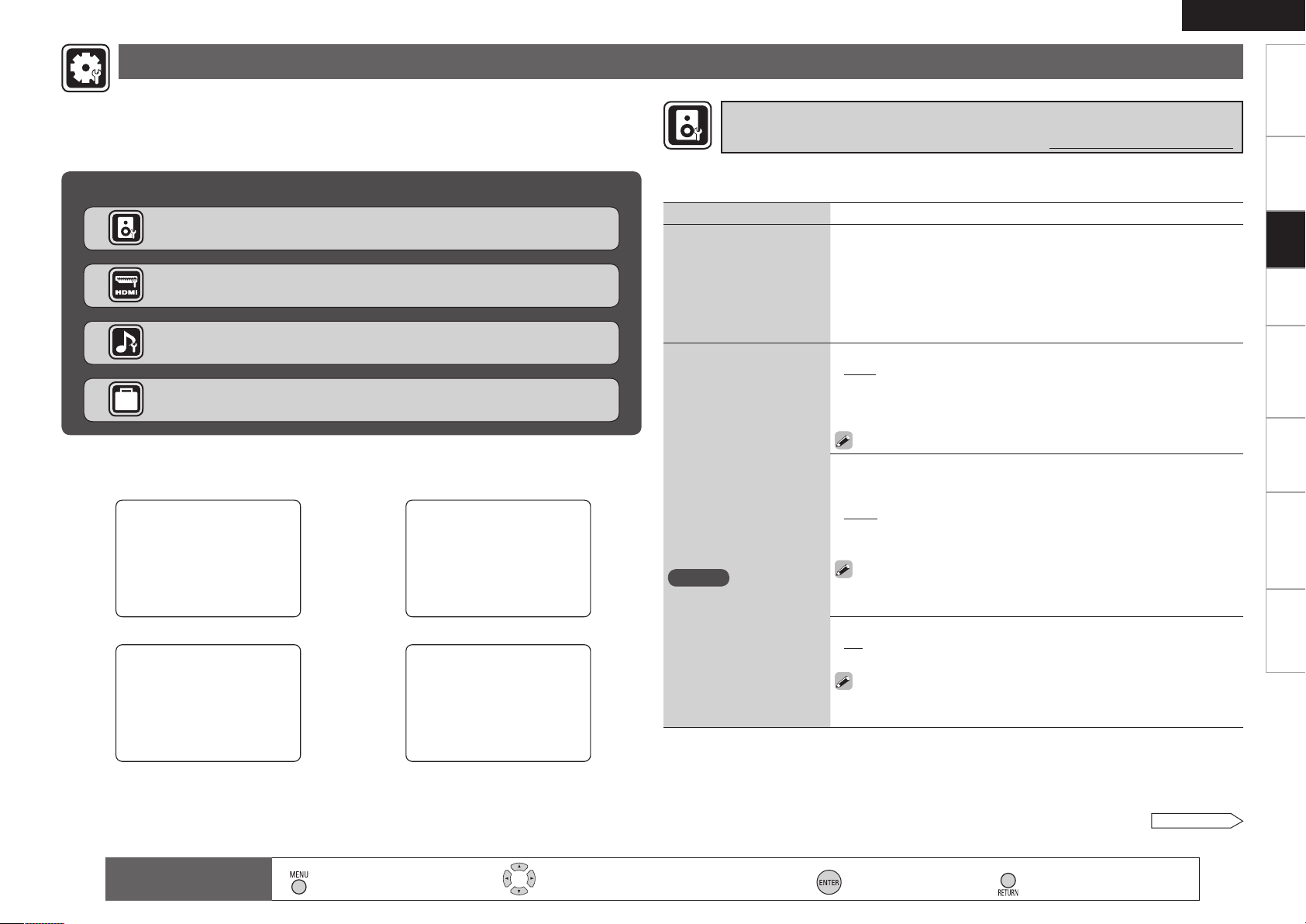
Making detailed settings (Manual Setup)
4-1.Speaker Setup
1.Pre Assign
2.Speaker Config.
3.Bass Setting
4.Distance
6.Crossover Freq.
5.Channel Level
[ENT]:Select [RTN]:Back
4-2.HDMI Setup
Auto Lipsync : ON
HDMI Audio Out : Amp
HDMI Control : OFF
[RTN]:Back
4-3.Audio Setup
1.Auto Surround Mode
2.EQ Customize
[ENT]:Select [RTN]:Back
4-4.Option Setup
1.Volume Control
2.Source Delete
3.On-Screen Display
4.Quick Select Name
5.Setup Lock
[ENT]:Select [RTN]:Back
ENGLISH
Getting Started
Use this procedure to change the Audyssey Auto Setup settings or to change the various audio,
video and display settings.
The set can be used without changing these settings. Make these settings as necessary.
For a description of “Menu map” and operating instructions, see page 17.
Items that can be set with the Manual Setup proceduren
Making the speaker settings (Speaker Setup) vpage 24
Making the HDMI settings (HDMI Setup) vpage 27
Making the audio settings (Audio Setup) vpage 28
Making other settings (Option Setup) vpage 28
n Examples of Menu Screen Displays
Speaker Setup HDMI Setup
Audio Setup Option Setup
Making the speaker settings (Speaker Setup)
Default settings are underlined.
Use this procedure to set the speakers manually or if you wish to change the settings made with
the Audyssey Auto Setup procedure.
Setting items Setting contents
Pre Assign
Sets the signal output
from the SURR. BACK /
FRONT HEIGHT PRE OUT
connectors.
Speaker Config.
Select speaker configuration
and size.
(bass reproduction capability)
NOTE
Select “Large” or “Small” not
according to the physical size
of the speaker but according
to the low frequency
reproduction capabilities
based on the frequency set
at “Crossover Frequency”
(vpage 26).
Normal :The surround back channel audio signals are output.
Front Height : The front height channel audio signals are output.
Front : Set the front speaker size.
Large : Use of a large speaker that can adequately play back low
•
frequencies.
Small : Use of a small speaker that has inadequate playback capacity for
•
low frequencies.
If “Subwoofer” is set to “No”, “Front” is automatically set to “Large”.
Center : Set the presence and size of the center speaker.
Large : Use of a large speaker that can adequately play back low
•
frequencies.
Small : Use of a small speaker that has inadequate playback capacity for
•
low frequencies.
None : Select when a center speaker is not connected.
•
• “Large” is not displayed when “Front” is set to “Small”.
• Even if “Center” has been set to “Large”, when “Front” is set to
“Small”, the “Center” setting automatically switches to “Small”.
Subwoofer : Set the presence of a subwoofer.
•
Yes : Use a subwoofer.
•
No : Select when a subwooofer is not connected.
•
When “Front” is set to “Small”, “Subwoofer” can automatically set
to “Yes”.
Connections Playback Remote Control Information Troubleshooting
Settings
Specifications
Remote control
operation buttons
Displaying the menu
:
Cancel the menu
: Moves the cursor (Up/Down/Left/Right)
: Decision the setting
: Return to previous menu
See overleaf
Page 28

ENGLISH
Getting Started Connections Playback Remote Control Information Troubleshooting Specifications
Making detailed settings (Manual Setup)
Setting items Setting contents
Speaker Config.
Select speaker configuration
and size.
(bass reproduction capability)
Settings
“S.Back” is displayed
when the “Pre Assign”
setting (vpage 24) is
set to “Normal”.
“Front Height” is
displayed when the “Pre
Assign” setting (vpage
24) is set to “Front
Height”.
NOTE
Select “Large” or “Small” not
according to the physical size
of the speaker but according
to the low frequency
reproduction capabilities
based on the frequency set
at “Crossover Frequency”
(vpage 26).
Surround : Set the presence and size of the Surround speakers.
Large : Use of a large speaker that can adequately play back low
•
frequencies.
Small :Use of a small speaker that has inadequate playback capacity for
•
low frequencies.
None : Select when the surround speakers are not connected.
•
“Large” is not displayed when “Front” is set to “Small”.
S.Back (Pre out) : Set the presence, size and number of surround back
speakers.
Large : Use of a large speaker that can adequately play back low
•
frequencies.
Small : Use of a small speaker that has inadequate playback capacity for
•
low frequencies.
None :Select when the surround back speakers are not connected.
•
2ch :Use two surround back speakers.
•
1ch : Use only one surround back speaker. Surround back audio is output
•
from the SURR. BACK / FRONT HEIGHT PRE OUT “L” connector.
• “Large” is not displayed when “Surround” is set to “Small”.
• Even if “S.Back” is set to “Large”, the “S.Back” setting is automatically
switched to “Small” if “Surround” is set to “Small”.
NOTE
Even when the Surround Back Speaker setting is other than “None”,
sound may not be emitted from the surround back speaker, depending
on the playback source. In this case, “Surround Back” setting other
than “OFF” (vpage 40).
Front Height (Pre out) : Set the front height speaker size.
Large : Use of a large speaker that can adequately play back low
•
frequencies.
Small : Use of a small speaker that has inadequate playback capacity for
•
low frequencies.
None : Select when a front height speaker is not connected.
•
• “Large” is not displayed when “Front” is set to “Small”.
• Even if “Front Height” is set to “Large”, the “Front Height” setting
is automatically switched to “Small” if “Front” is set to “Small”.
Setting items Setting contents
Bass Setting
Make the settings related to
playback of low frequency
signals (subwoofer and LFE).
This can be set when
“Speaker Config.” –
“Subwoofer” (vpage
24) is set to “Yes”.
Distance
Set the distance from the
listening position to the
speakers.
Measure the distance from
the listening position to the
speakers beforehand.
Subwoofer Mode : Select low range signal to be reproduced by
subwoofer.
LFE : Add the low frequency signal of the channel for which the speaker
•
size is set to “Small” to the subwoofer signal and output it.
LFE+Main : Add the low frequency signal of all channels to the subwoofer
•
signal and output it.
• Play music or a movie source and select the mode offering the
strongest bass.
• Select “LFE+Main” if you want the bass signals to always be
produced from the subwoofer.
LPF for LFE : Set the upper limit of the low frequency signals output from
the subwoofer.
80Hz / 90Hz / 100Hz / 110Hz / 120Hz / 150Hz / 200Hz / 250Hz•
Unit : Set the unit of distance.
Feet
•
Meters
•
Step : Set the minimum variable width of the distance.
1ft / 0.1ft
•
0.1m / 0.01m
•
FL (Front L)/ FR (Front R)/ C (Center)/ SW (Subwoofer)/ SL (Surround L)/
•
SR (Surround R/ SBL (Surr. Back L)/ SBR (Surr. Back R)/ FHL (Front Height L)/
FHR (Front Height R) : Select the speaker you want to set, and set the
distance. Set the value that is closest to the measured distance.
0.0ft ~ 60.0ft / 0.00m ~ 18.00m
•
• The speakers that can be selected differ depending on the “Pre Assign”
(vpage 24) and “Speaker Config.” settings.
• Default settings :
Front/Center/Subwoofer/Front Height : 3.6 meters (12 feet)
Surround/Surr. Back : 3.0 meters (10 feet)
NOTE
Set the difference in the distance between the speakers to less than 6.0
meters (20 feet). “Relocate Speaker” is displayed on the screen if an
inappropriate distance is set.
Default : Reset all distance settings to factory default.
Yes : Reset to the defaults.
•
No : Do not reset to the defaults.
•
Remote control
operation buttons
Displaying the menu
:
Cancel the menu
: Moves the cursor (Up/Down/Left/Right)
: Decision the setting
: Return to previous menu
Page 29

ENGLISH
Making detailed settings (Manual Setup)
Getting Started
Setting items Setting contents
Channel Level
Set the volume of the test
tone to be the same when it
is output from each speaker.
Crossover Frequency
Outputs at below set
frequency, each speaker’s
bass signal output from the
subwoofer. Set this according
to the low frequency
reproduction capabilities of
the speakers you are using.
This can be set when
“Speaker Config.” –
“Subwoofer” (vpage
25) is set to “Yes” or
“No”.
Test Tone Start : Output test tones.
FL (Front L)/ C (Center)/ FR (Front R)/ SR (Surround R)/
SBRz (Surround Back R)/ SBLz (Surround Back L)/ SL (Surround L)/
FHL (Front Height L)/ FHR (Front Height R)/ SW (Subwoofer):Select
the speaker.
z
When the “S.Back” setting (vpage 25) is set to “1ch”, “SB” is
displayed.
–12.0dB ~ +12.0dB (0.0dB) : Adjust the volume.
•
• When “Channel Level” is adjusted, the adjusted values are set for
all the surround modes. To adjust the channel level separately for the
different surround modes, use the operation see “Adjust the volume of
the different speakers” (vpage 45).
• Speakers set to “None” in the “Speaker Config.” (vpage 25) settings
are not displayed.
• Wheno is pressed while the subwoofer volume is set to “–12dB”, the
“Channel Level” setting switches to “OFF”.
• If output of the test tones begins while the muting mode is set, the
muting mode is canceled.
Default : Reset all channel level settings to factory default.
Yes : Reset to the defaults.
No : Do not reset to the defaults.
Crossover : Outputs at below set frequency, each speaker’s bass signal
output from the subwoofer.
40Hz / 60Hz / 80Hz / 90Hz / 100Hz / 110Hz / 120Hz / 150Hz / 200Hz /
•
250Hz
Advanced : Set the low frequency signals to be output from the signals
•
of the respective speakers to the subwoofer.
Front / Center / Surround / S.Back / Front Height : Select the speaker.
•
· 40Hz / 60Hz / 80Hz / 90Hz / 100Hz / 110Hz / 120Hz / 150Hz / 200Hz /
250Hz : Set the crossover frequency.
Setting items Setting contents
Crossover Frequency
• Always set the crossover frequency to “80 Hz”. When using small
speakers, however, we recommend setting the crossover frequency
to a higher frequency.
• For speakers set to “Small”, sound below the crossover frequency
is cut from the sound output. The cut bass sound is output from the
subwoofer or front speakers.
• The speakers that can be set when “Advanced” is selected differ
according to the “Bass Setting” setting (vpage 25).
· When “LFE” is selected, speakers set to “Small” at “Speaker
Config.” (vpage 25) can be set.
· When “LFE+Main” is selected, speakers can be set regardless of
the speaker size setting.
Connections Playback Remote Control Information Troubleshooting
Settings
Specifications
Remote control
operation buttons
Displaying the menu
:
Cancel the menu
: Moves the cursor (Up/Down/Left/Right)
: Decision the setting
: Return to previous menu
Page 30
ENGLISH
Getting Started Connections Playback Remote Control Information Troubleshooting Specifications
Making detailed settings (Manual Setup)
Making the HDMI settings(HDMI Setup)
Make settings for HDMI video/audio output.
Setting items Setting contents
Auto Lip Sync
Automatic compensation
Settings
for timing shift in audio and
video output.
HDMI Audio Out
Select HDMI audio output
device.
HDMI Control
External devices can be
controlled from the AVR590 and the AVR-590 can
be controlled from external
devices.
NOTE
The HDMI control
function controls
operations of a TV that
is compatible with the
HDMI control function.
Make sure that the TV
and HDMI are connected
when you perform HDMI
control.
Default settings are underlined.
ON : Compensated.
OFF : Not compensated.
Amp : Use speakers connected to AVR-590 for audio playback.
TV : Use speakers of TV for audio playback.
NOTE
When the HDMI control function is operating, the setting of audio playback
in the connected TV takes priority (vpage 44 “Controlling HDMI-
compatible devices from the AVR-590 (HDMI Control Function)”).
ON : Use the HDMI control function.
OFF : Do not use the HDMI control function.
• Please consult the operating instructions for each connected device
to check the settings.
• For details on the HDMI control function, see “Controlling HDMIcompatible devices from the AVR-590 (HDMI Control Function)”
(vpage 44).
NOTE
• When “Control” is set to “ON”, it consumes more standby power.
• When not using this unit for a long period, we recommend that you press
to turn off (jOFF) the power.
• When the “HDMI Control” setting has been changed, always turn off the
power to the connecting devices afterwards and then turn back on.
• The “HDMI Control” does not work when the power to the equipment is
off.
Setting items Setting contents
Power Off Control
The power of the AVR-590
and external device turn off
together.
This can be set when
“HDMI Control” is set
to “ON”.
ON:Switched.
OFF:Not switched.
• Please consult the operating instructions for each connected device
to check the settings.
• For details on the HDMI control function, see “Controlling HDMIcompatible devices from the AVR-590 (HDMI Control Function)”
(vpage 44).
Standby Source
Set the HDMI connector for
HDMI signal input during
standby.
This can be set when
“HDMI Control” is set
to “ON”.
Remote control
operation buttons
Last : Standby with last used input source during power on.
HDMI1 / HDMI2 / HDMI3 : The standby mode is set at the input source
assigned to the respective.
Displaying the menu
:
Cancel the menu
: Moves the cursor (Up/Down/Left/Right)
: Decision the setting
: Return to previous menu
Page 31

ENGLISH
Making detailed settings (Manual Setup)
Getting Started
Making the audio settings (Audio Setup)
Make settings for audio playback.
Setting items Setting contents
Auto Surround Mode
Make setting for memorizing
surround mode setting for
each input signal type.
EQ Customize
Set so that unused equalizer
settings are not displayed
when
is used.
ON : Memorize settings. Most recently stored surround mode is
automatically selected.
OFF : Do not memorize settings. Surround mode does not change
according to input signal.
The auto surround mode function lets you store in the memory the
surround mode last used for playing the four types of input signals
listed below.
q Analog and PCM 2-channel signals
w Dolby Digital and DTS 2-channel signals
e Dolby Digital and DTS multi-channel signals
r Multi-channel signals other than Dolby Digital and DTS (PCM, etc.)
Audyssey Byp. L/R / Audyssey Flat / Manual
Used
•
Not Used
•
NOTE
• Set so that the “Audyssey Byp. L/R” and “Audyssey Flat” settings can be
made when the Audyssey Auto Setup procedure is performed.
• Equalizer settings for which “Not Used” is set with the Quick Select
function cannot be stored and called out.
Default settings are underlined.
Making other settings (Option Setup)
Setting items Setting contents
Volume Control
Set the MAIN ZONE volume
setting.
Source Delete
Remove input sources
that are not used from the
display.
On-Screen Display
Make the settings related to
displays on the TV screen.
Volume Display : Set the volume display method.
Relative : The volume is displayed within the range of – – –dB (Minimum),
•
–80 dB ~ +18 dB.
Absolute : The volume is displayed within the range of 0, 1 ~ 99.
•
Vol.Limit : Make a setting for maximum volume.
OFF : Do not set a maximum volume.
•
–20dB(61) / –10dB(71) / 0dB(81)
•
Power On Level : This sets the volume set when the MAIN ZONE’s power
is turned on.
Last : Use the memorized setting from the last session.
•
– – – : Always use the muting on condition when power is turned on.
•
–80dB(1) ~ +18dB(99) : The volume is adjusted to the set level.
•
Mute Level : This sets the amount of attenuation of the volume when the
mute mode is set in the MAIN ZONE.
Full : The sound is cut off entirely.
•
–40dB : The sound is attenuated by 40 dB.
•
–20dB : The sound is attenuated by 20 dB.
•
TUNER / DVD / HDP / TV / SAT/CBL / VCR / DVR / V.AUX : Select the
sources you do not want to use.
ON : Use this source.
•
Delete : Do not use this source.
•
NOTE
•The currently selected input source cannot be set.
•Input sources set to “Delete” cannot be selected using .
Screensaver : Make screensaver settings.
ON : The screen switches to the screensaver if no operation is performed
•
for approximately 3 minutes while a menu is displayed or while an iPod
screen is displayed. When you press uio p, the screen saver is
cancelled and the screen before that screen saver started is displayed.
OFF : Turn the screensaver function off.
•
Text : The mode name is displayed when the operation for switching the
surround mode, input mode, etc., is performed.
ON : Turn display on.
•
OFF : Turn display off.
•
Master Volume : Master volume display during adjustment.
Bottom : Displayed at the bottom of the screen.
•
Top : Displayed at the top of the screen.
•
OFF : Turn display off.
•
Default settings are underlined.
Connections Playback Remote Control Information Troubleshooting
Settings
Specifications
Remote control
operation buttons
Displaying the menu
:
Cancel the menu
: Moves the cursor (Up/Down/Left/Right)
: Decision the setting
: Return to previous menu
See overleaf
Page 32

ENGLISH
Getting Started Connections Playback Remote Control Information Troubleshooting Specifications
Making detailed settings (Manual Setup)
Setting items Setting contents
On-Screen Display
Make the settings related to
displays on the TV screen.
Settings
Quick Select Name
Change the Quick Select
name.
Tuner Information : This sets the time the on-screen display is displayed
when a tuneroperation is performed.
Always : Show display continuously.
•
30sec : Show display for 30 seconds after operation.
•
10sec : Show display for 10 seconds after operation.
•
OFF : Turn display off.
•
iPod Information
when an iPodoperation is performed.
Always : Show display continuously.
•
30sec : Show display for 30 seconds after operation.
•
10sec : Show display for 10 seconds after operation.
•
OFF : Turn display off.
•
Rename Label : Change the display name of the selected “Quick Select”
setting.
1. Use ui to select the name of the Quick Select setting you want
to change, then press .
2.Use o p to set the cursor to the character you want to change.
3. Use ui to change the character, then press .
• Up to 16 characters can be input.
• The input character type can be switched by pressing while the
display name is being changed.
• The types of characters that can be input are as shown below.
GCapital lettersHA B C D EFGHIJ K L M NOPQRSTUV W X Y Z
GSmall lettersH abcde f g h ijklmn o p q rstuvwxy z
GSymbolsH ’ ( ) b + – . / : ; < = > ? [ ]
GNumbersH 0123456 7 8 9 (space)
4. Repeat steps 2 and 3 to change the display name.
Template : The display name can be changed by selecting “Operation” and
“Device Name” from the previously set templates.
1. Use ui to select the name of the Quick Select setting you want
to change, then press .
2. Use ui to select “Template”, then press .
3. Useui to select “Operation”, then press .
• Watch / Listen to / Play / For
4. Useuio p to select “Device Name ”, then press .
• DVD / Blu-Ray / HDP / TV / Cable TV / Satellite / VCR / DVR / iPod /
V.AUX / LD / Movie (When “Operation” is selected to “Watch”.)
• CD / TUNER / iPod / MD / TAPE / MUSIC (When “Operation” is
selected to “Listen to”.)
• PC / Game (When “Operation” is selected to “Play”.)
• Father / Mother / Son / Daughter / Brother / Sister / Grandfather
/ Grandmother / Me (When “Operation” is selected to “For”.)
:
This sets the time the on-screen display is displayed
Setting items Setting contents
Quick Select Name
Setup Lock
Protect settings from
inadvertent change.
Default : The changed display names are reset to the defaults.
Yes : Reset to the defaults.
•
No : Do not reset to the defaults.
•
ON : Turn protection on.
•
OFF : Turn protection off.
•
When “Setup Lock” is set to “ON”, the settings listed below can
no longer be changed. Also, “SETUP LOCKED!” is displayed if you
attempt to operate related settings.
・RESTORER ・Dynamic Volume
・MultEQ ・Channel Level
・Dynamic EQ ・Audio Delay
Remote control
operation buttons
Displaying the menu
:
Cancel the menu
: Moves the cursor (Up/Down/Left/Right)
: Decision the setting
: Return to previous menu
Page 33

Making the input settings (Input Setup)
5-1-1.Input Assign
HDMI Digi Comp
DVD 1 1
HDP 2
TV 01
VCR/iPod
DVR 02 2
SAT/CBL 3 C1
[ENT]:Select [RTN]:Back
5-2.Input Mode
Input Mode : Auto
Decode Mode : Auto
[RTN]:Back
5-3.Rename
DVD : DVD
Defaulut
[ ]:Up/Down [ ]:Rename
[RTN]:Back
5-4.Source Level
[RTN]:Back
Source Level : 0dB
5-5.iPod Playback Mode
Shuffle Mode : OFF
[RTN]:Back
Repeat Mode : One
5-1.Auto Preset
Auto Tuning
Preset Station Memory
Storing Preset Memory
Start
[ENT]:Start [RTN]:Back
5-2.Preset Skip
Block : A
A Block Presets: ON
A1 FM 87.50MHz : ON
A2 FM 89.10MHz : ON
A4 FM107.90MHz : ON
A3 FM 98.10MHz : ON
A5 FM 90.10MHz : ON
A6 FM 90.10MHz : ON
A7 FM 90.10MHz : ON
A8 FM 90.10MHz : ON
5-3.Preset Name
Block: A
A1FM 87.50MHz:
A2FM 89.10MHz:
A3FM 98.10MHz:
A5FM 90.10MHz:
A4FM107.90MHz:
A6FM 90.10MHz:
A7FM 90.10MHz:
A8FM 90.10MHz:
[ENT]:Select [RTN]:Back
ENGLISH
Getting Started
Make the settings related to the currently selected input source.
Before displaying the menu screen, press to switch to the input source to be set.
The items that can be set differ according to the selected input source.
The set can be used without changing these settings. Make these settings as necessary.
For a description of “Menu map” and operating instructions, see page 17.
Items that can be set with the Input Setup proceduren
Changing the Input Sources Assigned to the Input Connectors (Assign)
vpage 31
Changing the Input Source’s Input Mode and Decoding mode (Input
mode) vpage 32
Changing the Input Source’s Display Name (Rename) vpage 32
Correcting the Input Source’s Playback Level (Source Level)
vpage 33
Setting the iPod Playback Mode (iPod Playback Mode) vpage 33
Presetting Radio Stations (Auto Preset) vpage 33
n Examples of Menu Screen Displays
Assign Input Mode Rename
Connections Playback Remote Control Information Troubleshooting
Settings
Source Level iPod Playback Mode
Auto Preset Preset Skip Preset Name
Setting the Preset Channels to be Skipped (Preset Skip) vpage 33
Assign Name to a Preset Memory (Preset Name) vpage 33
Remote control
operation buttons
Displaying the menu
:
Cancel the menu
: Moves the cursor (Up/Down/Left/Right)
: Decision the setting
: Return to previous menu
Specifications
0
Page 34

ENGLISH
Getting Started Connections Playback Remote Control Information Troubleshooting Specifications
Changing the Input Sources Assigned to the Input Connectors
(Assign)
Setting items Setting contents
Input Assign(HDMI)
Assign input sources to input
Settings
connectors.
Input Assign(Digital)
Assign input sources to input
connectors.
Default settings are underlined.
HDMI : The
sources are assigned to the HDMI input connectors as shown below.
HDMI1 / HDMI2 / HDMI3
•
None : Do not assign an HDMI input connector to the currently selected
•
input source.
bUpon purchase, the settings of the different input sources are as shown
below.
Input
source
Default
setting
•When HDMI is assigned to an input source, the audio signal switches
to HDMI along with the video signal. To use with the digital audio
input connectors assigned, set menu “Input Mode” (vpage 32) to
“Digital”.
• When the AVR-590 and TV are connected with an HDMI cable, if the
TV is not compatible with HDMI audio signal playback, only the video
signals are output to the monitor.
• The audio signals input from the analog, digital and EXT. IN connectors
are not output to the TV.
DVD HDP TV SAT/CBL VCR DVR V.AUX
DVD HDP TV SAT/CBL VCR DVR V.AUX
HDMI1 HDMI2 None HDMI3 None None None
input
NOTE
When “HDMI Control” is set to “ON”, HDMI cannot be assigned to “TV”
at the “HDMI” settings (vpage 27).
Digital : The
sources are assigned to the digital audio input connectors as shown
below.
C1 (COAXIAL) / O1 (OPT1) / O2 (OPT2)
•
None : Do not assign a digital input connector to the currently selected
•
input source.
bUpon purchase, the settings of the different input sources are as shown
below.
Input source DVD HDP TV SAT/CBL VCR
Default setting None None OPT1 COAXIAL None
DVD HDP TV SAT/CBL VCR DVR V.AUX
input
Setting items Setting contents
Input Assign(Component)
Assign input sources to input
connectors.
iPod Dock
Change the input source to
which the control dock for
iPod is assigned.
Component : The
input sources are assigned to the component video input connectors as
shown below.
COMP1 (Component video 1 input connector) / COMP2 (Component
●
video 2 input connector)
None
: Do not assign the component video input connectors to the currently
●
selected input source.
bUpon purchase, the settings of the different input sources are as shown
below.
Input
source
Default
setting
The control dock for iPod can be assigned to the
DVR V.AUX
Assign
: Assign the currently selected input source to the Control Dock for
iPod input.
None
: Do not assign the currently selected input source to the Control Dock
for iPod input.
• With the default settings, the control dock for iPod can be used
connected to the VCR (iPod) connector.
• Even if “iPod Dock” is set to “Assign”, if AVR-590 and control dock
for iPod are not connected, the input is used as the normal input
source.
DVD HDP TV SAT/CBL VCR DVR V.AUX
DVD HDP TV SAT/CBL VCR DVR V.AUX
COMP1 None None None None COMP2 None
input sources.
Making the input settings (Input Setup)
DVD SAT/CBL VCR
Input source
Default setting OPT2 None
Remote control
operation buttons
DVR V.AUX
Displaying the menu
:
Cancel the menu
: Moves the cursor (Up/Down/Left/Right)
: Decision the setting
: Return to previous menu
Page 35

ENGLISH
Auto HDMI Digital Analog
Making the input settings (Input Setup)
Getting Started
Changing the Input Source’s Input Mode and Decoding mode
(Input Mode)
Default settings are underlined.
The selectable input modes depend on the input source and “Assign” setting (vpage
31 “Changing the input sources assigned to the input connectors”).
Setting items Setting contents
Input Mode
Set the audio input modes for
the different input sources.
Auto : Automatically detect input signal and perform playback.
HDMI : Play only signals from HDMI input.
Digital : Play only signals from digital input.
Analog : Play only signals from analog input.
bUpon purchase, the settings of the different input sources are as shown
below.
Input
source
Default
setting
Input
source
Default
setting
•The “HDMI” settings are made for input sources for which HDMI
input connectors are assigned at “Assign” (vpage 31).
•The “Digital” settings are made for input sources for which digital
input connectors are assigned at “Assign” (vpage 31).
•
When a digital signal is properly input, the “ ” indicator lights on
the display. If the “ ” indicator does not light, check the digital
input connector assignment and the connections.
•
This can also be set by pressing or .
Each time you press the button, the input mode display will change.
DVD HDP TV SAT/CBL VCR
Auto HDMI Digital Auto Analog
DVR V.AUX TUNER
Auto Analog Analog
Setting items Setting contents
Decode Mode
Set the input source’s
decoding mode.
Auto : Detect type of digital input signal and decode and play
automatically.
PCM : Decode and play only PCM input signals.
DTS : Decode and play only DTS input signals.
• This can be set for input sources for which “HDMI” or “Digital” is
assigned at “Assign” (vpage 31).
• Normally set this to “Auto”.
Changing the Input Source’s Display Name (Rename)
Default settings are underlined.
Use this procedure to change the display name of the currently selected input source.
Setting items Setting contents
Rename
Change the input source’s
display name to the desired
name.
Default
The changed display names
are reset to the defaults.
1.Use o p to set the cursor to the character you want to change.
2.Use ui to change the character, then press .
Up to 8 characters can be input.
•
The input character type can be switched by pressing while the
•
display name is being changed.
• The types of characters that can be input are as shown below.
GCapital lettersHA B C D EFGHIJ K L M NOPQRSTUV W X Y Z
GSmall lettersH abcde f g h ijklmn o p q rstuvwxy z
GSymbolsH ’ ( ) b + – . / : ; < = > ? [ ]
GNumbersH 0123456 7 8 9 (space)
Yes : Reset to the defaults.
No : Do not reset to the defaults.
Connections Playback Remote Control Information Troubleshooting
Settings
Specifications
Remote control
operation buttons
Displaying the menu
:
Cancel the menu
: Moves the cursor (Up/Down/Left/Right)
: Decision the setting
: Return to previous menu
Page 36

ENGLISH
Getting Started Connections Playback Remote Control Information Troubleshooting Specifications
Making the input settings (Input Setup)
Correcting the Input Source’s Playback Level
(Source Level)
Default settings are underlined.
Use this procedure to correct the playback level of the currently selected input source's audio input.
Set this if there are differences in the input volume levels between the different sources.
Setting items Setting contents
Settings
Source Level
Correct the playback level of
the audio input.
–12dB ~ +12dB (0dB)
Setting the iPod Playback Mode (iPod Playback Mode)
Default settings are underlined.
This can be selected for input sources for which “Assign” is assigned at the “iPod Dock” (vpage
31) setting.
Setting items Setting contents
Repeat
Make settings for repeat
mode.
Shuffle
Make settings for shuffle
mode.
All : Repeat all songs.
One : Repeat the current song.
OFF : Cancel repeat mode.
n When DENON control dock for iPod ASD-1R or ASD-11R is
connected
Songs : Shuffle all songs.
Albums : Shuffle songs from current album only.
OFF : Cancel shuffle mode.
Presetting Radio Stations (Auto Preset)
Default settings are underlined.
Setting items Setting contents
Auto Preset
Use the auto preset function
to program radio stations.
This can be set when the source is set to
Start : Start the auto preset process.
TUNER
.
Setting the Preset Channels to be Skipped (Preset Skip)
Default settings are underlined.
Setting items Setting contents
Preset Skip
Set the preset memories that
you do not want to display
when tuning.
This can be set when the source is set to
A ~ G : Select the preset channel(s) you do not want to display.
ON : Display this number.
•
Skip : Skip this number.
•
If you set “Block Presets” to “Skip”, you can skip the preset memory
blocks (A to G).
TUNER
.
Assign Name to a Preset Memory(Preset Name)
Default settings are underlined.
Setting items Setting contents
Preset Name
Assign name to a preset
memory.
This can be set when the source is set to
1.Use ui to select the preset channel name you want to change,
then press .
2.Use o p to set the cursor to the character you want to change.
3.Use ui to change the character, then press .
• Up to 8 characters can be input.
• The input character type can be switched by pressing while the
display name is being changed.
• The types of characters that can be input are as shown below.
GCapital lettersHA B C D EFGHIJ K L M NOPQRSTUV W X Y Z
GSmall lettersH abcde f g h ijklmn o p q rstuvwxy z
GSymbolsH ’ ( ) b + – . / : ; < = > ? [ ]
GNumbersH 0123456 7 8 9 (space)
4. Repeat steps 2 and 3 to change the display name.
TUNER
.
If an FM station cannot be preset automatically, select the desired station
by tuning it in manually, then preset it manually.
Remote control
operation buttons
Displaying the menu
:
Cancel the menu
: Moves the cursor (Up/Down/Left/Right)
: Decision the setting
: Return to previous menu
Page 37

Playback
ENGLISH
Getting Started
n Operation Flow
Before starting playback, make the connections between the
different components and the settings on the receiver.
Playing Components (vpage 34)
n Playing Blu-ray Disc/DVD Players (vpage 34)
n iPod® Playback (vpage 34)
n Listening to FM/AM Broadcasts (vpage 36)
n Operations During Playback (vpage 37)
Selecting the Surround Mode (vpage 37)
q Standard Playback (vpage 37)
w Playing in a DENON original surround mode
(vpage 38)
e Direct Playback (vpage 38)
r Stereo Playback (vpage 39)
Adjusting the Sound Field Effects (Parameter)
(vpage 39)
NOTE
●Also refer to the operating instructions of the connected
components when playing them.
●External devices can be controlled by remote control unit
(vpage 46 “Operating the Connected Devices by Remote
Control Unit”).
Playing Components
Playing Blu-ray Disc / DVD Players
The following describes the procedure for playing Blu-ray disc/
DVD players.
Use the same procedure to play other components.
Prepare for playback.
1
①Turn on the power of the TV, subwoofer
and player.
②Set the TV’s input to the AVR-590.
③Load the disc in the player.
Turn on the AVR-590’s power.
2
(vpage 16“Turning the Power On”)
Press and select the input
3
source.
If “TUNING PRESET” is selected for preset
channel, press before turning .
Play the component connected to the AVR-590.
4
Make the necessary settings on the player (language
setting, subtitles setting, etc.) beforehand.
Use to adjust the volume.
5
GVariable rangeH
※The variable range differs according to the input signal and channel
level setting.
Select the desired surround mode.
6
(vpage 37“Selecting the Surround Mode”)
– – – –80.0dB ~ 18.0dB
iPod® Playback
The music / video on an iPod can be played by using the control
dock for iPod (ASD-1R, ASD-11R, ASD-3N or ASD-3W sold
separately).
Connect the control dock for iPod beforehand. (vpage 14
“iPod®”).
Listening to music on an iPod
Prepare for playback.
1
q Set the iPod in the DENON control
dock for iPod.
w Assign the control dock for iPod’s input
(vpage 31).
eSwitch to “DEVICE”.
Turn on the AVR-590’s power.
2
(vpage 16“Turning the Power On”)
Press to select the input
3
source assigned in step 1-w
above.
b If the screens above are not
displayed, the iPod may not be
properly connected. Try connecting
again.
®
OK to disconnect.
(iPod screen)
Connections Remote Control Information Troubleshooting
Playback
SpecificationsSettings
Adjust the desired sound eld effects.
7
(vpage 39“Adjusting the Sound Field Effects”)
See overleaf
Page 38

ENGLISH
Getting Started Connections Remote Control Information Troubleshooting SpecificationsSettings
Press and hold it down for a 2 seconds or more to
4
select the display mode.
There are two modes for display the contents recorded on the
iPod.
Playback
Browse mode
Remote mode
Display mode
Playable
files
Active
buttons
z1: When using an ASD-11R, ASD-3N or ASD-3W control dock for
iPod.
z2: Video may not be output, depending on the combination of
ASD-1R or ASD-11R and iPod.
:Displayed on the TV screen.
:Displayed on the iPod’s screen.
Browse mode Remote mode
Audio file
Video file
Remote control
unit (AVR-590)
®
iPod
S S
S
S S
A S
1
z
Use ui to select the menu, then
5
press or p to select the music
or video le to be played.
Press or p.
6
Playback starts.
Use to adjust the volume.
7
GVariable rangeH
※The variable range differs according to the input signal and channel
level setting.
Select the desired surround mode.
8
(vpage 37“Selecting the Surround Mode”)
Adjust the desired sound eld effects.
9
(vpage 39“Adjusting the sound Field Effects”)
– – – –80.0dB ~ 18.0dB
Playing Components
n To stop
During playback, either press and hold
or press .
n Stopping playback temporarily
During playback, press or .
Press again to resume playback.
n To cue to the beginning of a
track
During playback, either press (to cue to
2
z
S
the current track) or (to cue to the next
track).
n Repeat playback and shuffle
Viewing Still Pictures or Videos on the iPod
Photo and video data on the iPod can be viewed on the monitor. Only
•
for iPod equipped with slideshow or video functions. (When using an
ASD-1R or ASD-11R)
Video may not be output, depending on the combination of ASD-1R
•
or ASD-11R and iPod.
Press and hold to set the Remote
1
mode.
“Remote iPod” is displayed on the AVR590’s display.
Watching the iPod’s screen,
2
use ui to select “Photos” or
“Videos”.
®
playback
“iPod Playback Mode” (vpage 33)
Use the RESTORER mode to expand the low and high frequency
•
components of compressed audio files and achieve a richer sound.
The default setting is “Mode3” (vpage 43).
To check the name of the title, the artist or the album when playing
•
in browse mode, press .
The time (default : 30 sec) for which the on-screen display are
•
displayed can be set at menu “iPod Information” (vpage 29).
Press uiop to return to the original screen.
Press and set the AVR-590’s power to the standby mode before
•
disconnecting the iPod. Also switch the input source to one to which
the menu “iPod dock” is not assigned before disconnecting the
iPod.
NOTE
Depending on the type of iPod and the software version, some
•
functions may not operate.
DENON will accept no responsibility whatsoever for any loss of iPod
•
data.
Press until the image you want to view is
3
displayed.
“TV Out” at the iPod’s “Slideshow Settings” or “Video Settings” must
be set to “On” in order to display the iPod’s photo data or videos on
the monitor. For details, see the iPod’s operating instructions.
iPod is a trademark of Apple Inc., registered in the U.S. and other
countries. The iPod may only be used to copy or play contents that
are not copyrighted or contents for which copying or playback is
legally permitted for your private use as an individual. Be sure to
comply with applicable copyright legislation.
Page 39
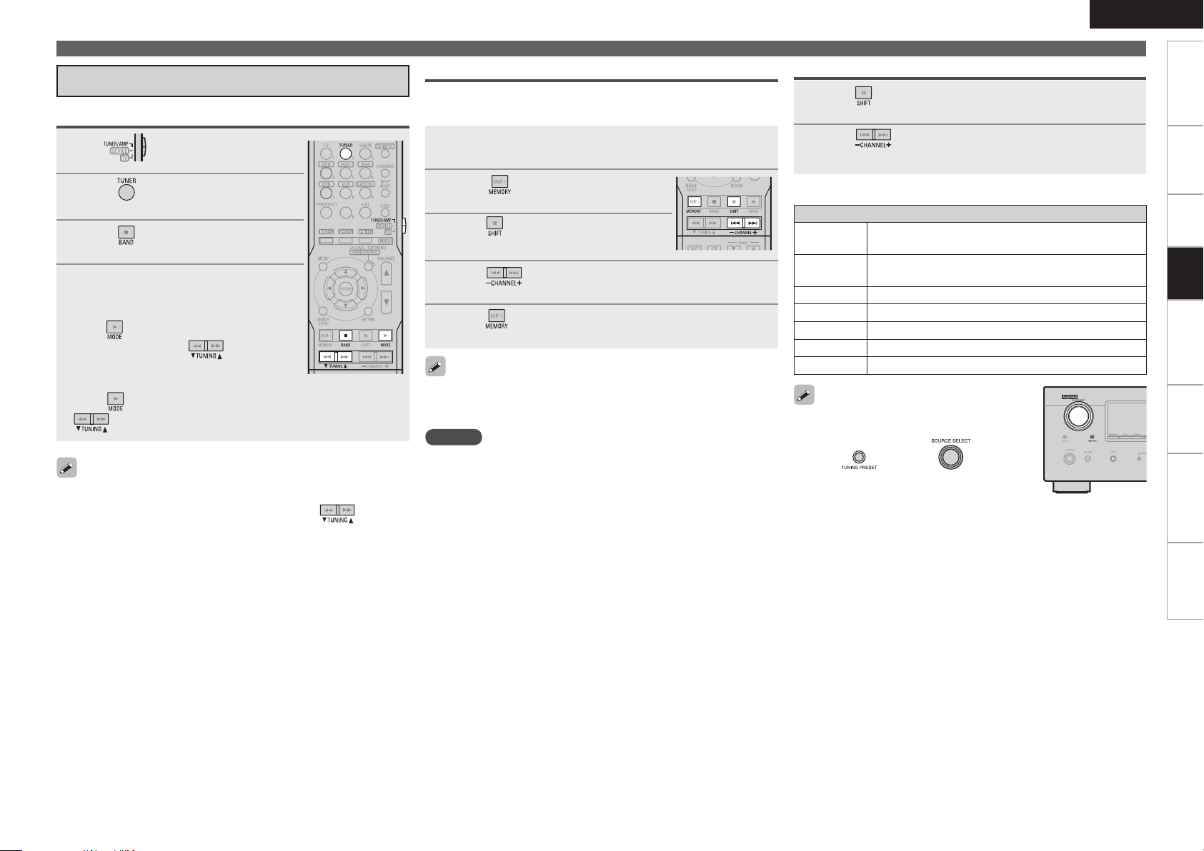
Listening to FM/AM Broadcasts
Basic Operation
Set to “TUNER/AMP”.
1
Press to select “TUNER”.
2
Press to select “FM” or “AM”.
3
Tune in the desired broadcast
4
station.
q To tune in automatically (Auto Tuning)
Press to light the “AUTO” indicator on
the display, then use to select the
station you want to hear.
w To tune in manually (Manual Tuning)
Press to turn off the display’s “AUTO” indicator, then use
to select the station you want to hear.
• If the desired station cannot be tuned in with auto tuning, tune it in
manually.
• When tuning in stations manually, press and hold to change
frequencies continuously.
• The time (default : 30 sec) for which the on-screen display are
displayed can be set at “On-Screen Display” (vpage 29).
Presetting Radio Stations (Preset Memory)
Your favorite broadcast stations can be preset so that you can tune
them in easily. Up to 56 stations can be preset.
Tune in the broadcast station you want to preset.
1
Press .
2
Press
3
in which the station is to be preset.
Press to select the preset number (1 to 8).
to select the block (A to G)
4
Press again to complete the setting.
5
• To preset other stations, repeat steps 1 to 5.
• Stations can be preset automatically at menu “Auto Preset” (vpage
33).
NOTE
Preset stations are erased by overwriting them.
Playing Components
Listening to Preset Stations
Press to select the memory block (A to G).
1
Press to select the desired preset channel (1 to
2
8).
n Default settings
Auto tuner presets
A1 ~ A8
B1 ~ B8
C1 ~ C8
D1 ~ D8
E1 ~ E8
F1 ~ F8
G1 ~ G8
You can also operate via the main unit. In this
case, perform the following operations.
• Press , then turn on the main
unit to select the preset radio channel.
87.5 / 89.1 / 98.1 / 107.9 / 90.1 / 90.1 / 90.1 /
90.1 MHz
520 / 600 / 1000 / 1400 / 1500 / 1710 kHz,
90.1 / 90.1 MHz
90.1 MHz
90.1 MHz
90.1 MHz
90.1 MHz
90.1 MHz
ENGLISH
Getting Started
Connections Remote Control Information Troubleshooting
Playback
SpecificationsSettings
Page 40
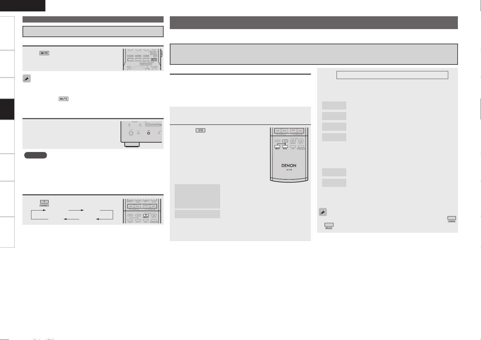
ENGLISH
Bright Dim
DarkOFF
Getting Started Connections Remote Control Information Troubleshooting SpecificationsSettings
Operations During Playback
Turning Off the Sound Temporarily (Muting)
Press .
Playing Components
Selecting the Surround Mode
Select a surround mode to enjoy surround playback with your favorite sound field effects.
q Playing sources according to the sources’ audio signal format/number of channels
(Standard Playback)
The sound is reduced to the level set at menu “Mute Level” (vpage
•
28).
To cancel, press again. Muting can also be canceled by adjusting
•
Playback
the master volume.
Listening with Headphones
Plug the headphones into the PHONES
jack on the main unit.
The sound from the speakers and pre-out
connectors is automatically cut.
NOTE
To prevent hearing loss, do not raise the volume level excessively
•
when using headphones.
Unplug headphones when performing the Audyssey Auto Setup
•
procedure or other settings.
Switching the brightness of the display
Press
.
Operations
The selectable surround modes depend on the following:
• Format of the audio signals being input
• Number of channels of the audio signals being input
• The set pre out assignment mode (vpage 24)
Playing the source (vpage 34).
1
Press to select the surround
2
mode.
n Multichannel sources
The surround modes that can be selected
differ according to the input source.
n 2channel sources
When you select “DOLBY PLgz”, set “Pre
Assign” to “Front Height”.
DOLBY PLgx,
DOLBY PLg
or
DOLBY PLgz
DTS NEO:6
: DOLBY PLgx can be selected when surround back speakers are
z
being used.
z
: The signals are decoded in DOLBY PLgx,
DOLBY PLg or DOLBY PLgz, for playback.
: The signals are decoded in DTS NEO:6 for
playback.
3
This is the operation for playing 2-channel sources.
Select the mode for the source at “Mode” (vpage
39).
n DOLBY PLgx, DOLBY PLg
Cinema
Music
Game
Pro Logic
: This mode is suited for movie sources.
: This mode is suited for music sources.
: This mode is suited for games.
: This is the Pro Logic playback mode. This can be
selected when playing with a DOLBY PLg decoder.
When this mode is selected, “DOLBY PL” is
displayed.
n DTS NEO:6
Cinema
Music
※The modes that can be selected depend on the input source
being played.
The “Cinema” and “Music” modes can also be set by pressing
or .
: This mode is suited for movie sources.
: This mode is suited for music sources.
Page 41
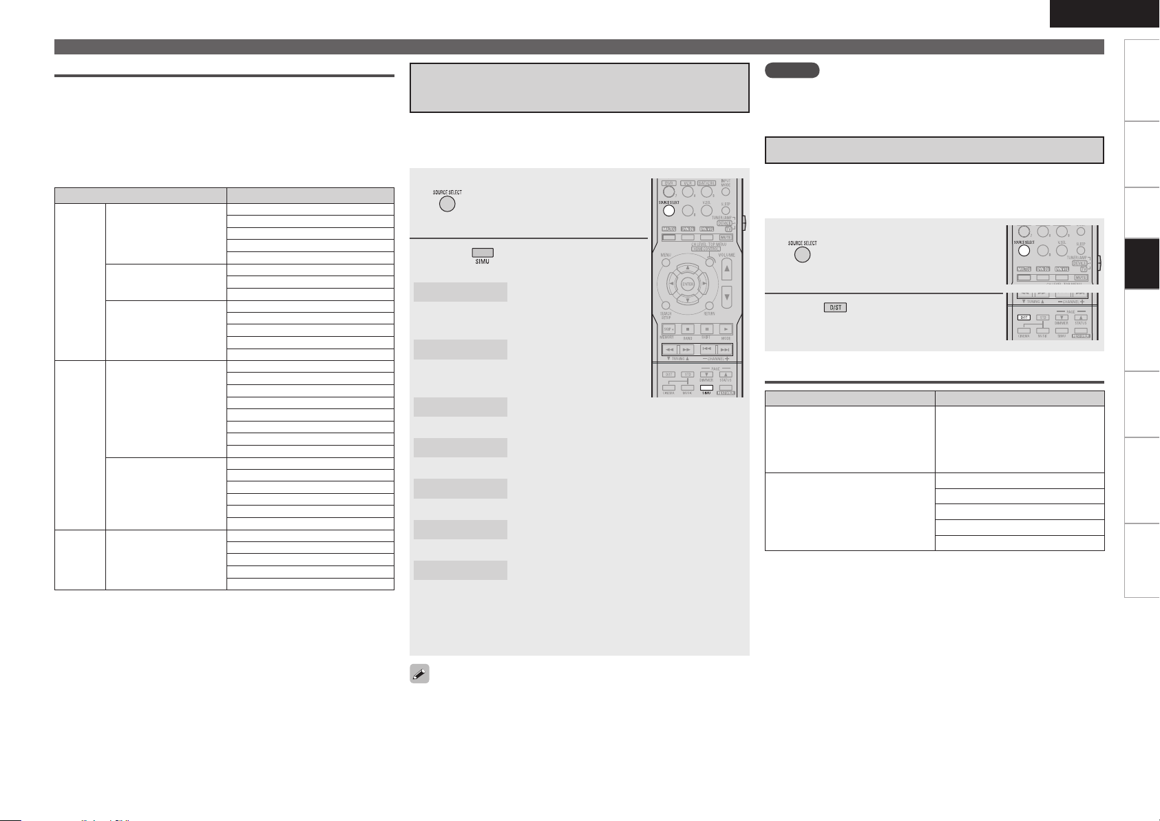
Displaying the currently playing surround mode
nSurround playback of multichannel sources
(Dolby Digital, DTS, etc.)
In the case of standard playback of multi channel sources, the
AVR-590 recognizes the format of the multi-channel audio input
signal and automatically operates the appropriate decoder for
surround sound.
Input signal Display
Dolby Digital
(other than 2ch)/
Dolby Digital EX
Dolby
Digital
DTS
PCM
z1:When a signal is input, the HD AUDIO indicator lights.
z2:This is displayed when the input signal is “DTS-ES Matrix 6.1”
z3:This is displayed when the input signal is “DTS-ES Discrete
z4:This is displayed when the input signal is “DTS 96/24”.
Dolby Digital Plus
(z1)
Dolby TrueHD (z1)
DTS (5.1ch)/
DTS-ES Discrete 6.1 /
DTS-ES Matrix 6.1 /
DTS 96/24
DTS-HD (z1)
PCM
(multi ch)
and the AVR-590’s “AFDM” setting (vpage 40) is set to “ON”.
6.1”.
DOLBY DIGITAL
DOLBY DIGITAL EX
DOLBY DIGITAL+PLgx CINEMA
DOLBY DIGITAL+PLgx MUSIC
DOLBY DIGITAL+PLgz
DOLBY DIGITAL++PLgx C
DOLBY DIGITAL++PLgx M
DOLBY DIGITAL++PLgz
DOLBY TrueHD
DOLBY HD+EX
DOLBY HD+PLgx CINEMA
DOLBY HD+PLgx MUSIC
DOLBY HD+PLgz
DTS SURROUND
DTS+PLgx CINEMA
DTS+PLgx MUSIC
DTS+PLgz
DTS+NEO:6
DTS ES MTRX6.1 (z2)
DTS ES DSCRT6.1 (z3)
DTS 96/24 (z4)
DTS-HD HI RES
DTS-HD MSTR
DTS-HD+NEO:6
DTS-HD+PLgx CINEMA
DTS-HD+PLgx MUSIC
DTS-HD+PLgz
MULTI CH IN
MULTI IN+PLgx CINEMA
MULTI IN+PLgx MUSIC
MULTI IN+PLgz
MULTI CH IN 7.1
w Playing in a DENON original surround
mode
The desired mode according to the program source and viewing
situation can be selected from among 7 DENON original surround
modes.
Select the input source by pressing
1
2
5CH/7CH STEREO
z1: When playing sources recorded in monaural in the MONO
Depending on the program source being played, it may not be possible
to achieve a satisfactory surround effect. In this case, try other modes
to achieve a sound field suited to your tastes.
and play the source (vpage
34).
Press to select the Surround
mode.
: This mode is for enjoying
stereo sound from all
speakers.
ROCK ARENA
JAZZ CLUB
MONO MOVIE
VIDEO GAME
MATRIX
VIRTUAL
MOVIE mode, the sound will be off balance with a single
channel (left or right), so input to both channels.
: This mode is for enjoying
the atmosphere of a live
concert in an arena.
: This mode is for enjoying the atmosphere of a
live concert in a jazz club.
: This mode is for playing monaural movie
sources with surround sound.
: This mode is suited for achieving surround
sound with video games.
: This mode lets you add a sense of expansion
to stereo music sources.
: This mode is for enjoying surround effects
using only the front speakers or headphones.
z1
ENGLISH
Selecting the Surround Mode
NOTE
When the input signal is DOLBY TrueHD, DOLBY DIGITAL Plus, DTSHD
you cannot select DENON original surround mode.
e Direct Playback
In this mode the signals bypass the tone adjustment circuitry for
high quality sound.
The sound is output to the same channels as the input signal.
Select the input source by pressing
1
and play the source (vpage
34).
Press to select the “DIRECT”.
2
Displaying the currently playing surround mode
Input signal Display
Analog signal /
PCM (2ch) /
Dolby Digital source /
DTS source /
Other 2-channel digital signals
PCM (multi ch)
DIRECT
MULTI CH DIRECT
M DIRECT + PLgx CINEMA
M DIRECT + PLgx MUSIC
M DIRECT + PLgz
M DIRECT 7.1
Getting Started
Connections Remote Control Information Troubleshooting
Playback
SpecificationsSettings
Page 42

ENGLISH
Getting Started Connections Remote Control Information Troubleshooting Specifications
Selecting the Surround Mode
r Stereo Playback
This is the mode for playing in stereo. The tone can be adjusted.
Sound is output from the front left and right speakers and
subwoofer.
Select the input source by pressing
1
Settings
and play the source (vpage
34).
Adjusting the Sound Field Effects (Parameter)
The sound being played in the surround mode can be adjusted to your liking.
The items (parameters) that can be adjusted depend on the signal being input and the currently set surround
mode. For details on the adjustable parameters, see “Surround Modes and Parameters” (vpage 51).
NOTE
Some of the setting items cannot be set while playback is stopped. Set these items during playback.
Adjusting the sound field effects (Surround Parameter)
Default settings are underlined.
Playback
Press to select the “STEREO”.
2
Setting items Setting contents
Mode
Set the play mode for
playing 2-channel sources in
surround.
n In the PLgx, PLg or PLgz mode
Cinema : This is the mode for cinema source.
Music : This is the mode for music source.
Game : This is the mode for game source.
ProLogic : Dolby Pro Logic playback mode (PLg mode only). (This is
the mode for 4-channel playback (front L, front R, center, surround
(MONO).)
n In the DTS NEO:6 mode
Cinema : This is the mode for cinema source.
Music : This is the mode for music source.
• The “Music” mode is also effective for movie sources including a
lot of stereo music.
• The “Cinema” and “Music” modes can also be set by pressing
or .
OFF : “Cinema EQ” is not used.
ON : “Cinema EQ” is used.
Low/Mid/High : These set the compression level.
OFF : Turn dynamic range compression off.
The “D.Comp” indicator lights when playing DTS source that supports
the “D.Comp” function.
Auto : Dynamic range compression of Dolby TrueHD sources turns on and
off automatically.
Low/Mid/High : These set the compression level.
OFF : Turn dynamic range compression off.
–10dB ~ 0dB
For proper playback of the different program sources, we recommend
setting to the values below.
• Dolby Digital sources : “0dB”
• DTS movie sources : “0dB”
• DTS music sources : “–10dB”
: Decision the setting
: Return to previous menu
Remote control
operation buttons
Displaying the menu
:
Cancel the menu
Cinema EQ
Soften the treble range of
movie sound tracks for better
understanding.
Dynamic Range
Compression (D.Comp)
Compress dynamic range
(difference between loud
and soft sounds).
Dynamic Range Control
(DRC)
Compress dynamic range
LFE
Adjust the low-frequency
effects level (LFE).
: Moves the cursor (Up/Down/Left/Right)
Page 43

ENGLISH
Adjusting the Sound Field Effect (Parameter)
Getting Started
Setting items Setting contents
Center Image
Assign center channel signal
to front left and right channels
for wider sound.
Panorama
Assign front L/R signal also
to surround channels, for
wider sound.
Dimension
Shift sound image center
to front or rear, to adjust
playback balance.
Center Width
Assign center channel signal
to front left and right channels
for wider sound.
Delay Time
Adjust delay time to control
sound stage size.
Effect Level
Adjust the strength of the
surround effect.
Room Size
Determine size of acoustic
environment.
NOTE
“Room Size” does not
indicate the size of the room
in which sources are played.
0.0 ~ 1.0 (0.3)
ON : Set.
OFF : Do not set.
0 ~ 6 (3)
0 ~ 7 (3)
0ms ~ 300ms (30ms)
1 ~ 15 (10)
Set to a lower level if the positioning and sense of phase of the
surround signals seems unnatural.
Small : Simulate acoustics of a small room.
Medium small : Simulate acoustics of a medium-small room.
Medium : Simulate acoustics of a medium room.
Medium large : Simulate acoustics of a medium-large room.
Large : Simulate acoustics of a large room.
Setting items Setting contents
AFDM (Auto Flag Detect
Mode)
Detects the source’s surround
back channel signal and sets
the optimum surround mode
automatically.
Surround Back
Sets the method of
generating of the surround
back channel.
ON : Set.
OFF : Do not set.
n For 2-channel sources
ON : The surround back channel is used.
OFF : No signal is played from the surround back channels.
n For multi channel sources
Set this to set the method of generating of the surround back channel
for sources that do not include surround back signals and when you
do not want to play the surround back signals included in the source.
Check the audio signals of the source being played before making this
setting.
OFF : No signal is played from the surround back channels.
MTRX ON : Generate and play the surround back signals from the
surround channel signals.
PLgx CINEMAz1 : Generate and play the surround back signals by
decoding the signals in the “Dolby Pro Logic gx Cinema” mode.
PLgx MUSICz2 : Generate and play the surround back signals by
decoding the signals in the “Dolby Pro Logic gx Music” mode.
ES MTRX : Generate and play the surround back signals from the
surround channel signals of the DTS source.
ES DSCRTz3 : Play the surround back signals included in the 6.1-
channel DTS source.
DSCRT ONz3 : Play the surround back signals included in the 7.1-
channel source.
z
1 : This can be selected when “S.Back” in the “Speaker Config.”
settings (vpage 25) is set to “2ch”.
z
2 : This can be selected when “S.Back” in the “Speaker Config.”
settings (vpage 25) is set to “2ch” or “1ch”.
z
3 : When “AFDM” is set to “ON”, the surround back channel is played
with the AFDM function. When selected while “AFDM” is set to
“OFF”, the source’s surround back signals are played.
This can also be set by pressing .
NOTE
This is valid when the “Pre Assign” setting (vpage 24) is set to “7.1channel surround back” or “6.1-channel surround back”, and when the
“S.Back” setting (vpage 25) is set to “Large” or “Small”.
Connections Remote Control Information Troubleshooting
Settings
Playback
Specifications
Remote control
operation buttons
Displaying the menu
:
Cancel the menu
: Moves the cursor (Up/Down/Left/Right)
: Decision the setting
: Return to previous menu
0
Page 44
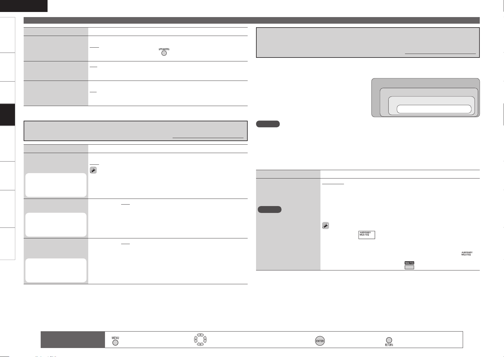
ENGLISH
Getting Started Connections Remote Control Information Troubleshooting Specifications
Adjusting the Sound Field Effect (Parameter)
Setting items Setting contents
Front Height
Set whether or not to use
the front height channel.
Subwoofer
Turn subwoofer output on
and off.
Settings
Default
Restores all the surround
parameter settings to their
defaults.
Playback
Adjusting the tone (Tone Control)
Setting items Setting contents
Tone Control
Sets the tone control function
ON and OFF.
This can be set when
“Dynamic EQ” (vpage
42) is set to “OFF”.
Bass
Adjusts the low frequencies.
This can be set when
“Tone Control” is set to
“ON”.
Treble
Adjusts the high
frequencies.
This can be set when
“Tone Control” is set to
“ON”.
ON : Use the front height channel.
OFF : Do not use the front height channel.
This can also be set by pressing
ON : The subwoofer is used.
OFF : The subwoofer is not used.
Yes : Reset to the defaults.
No : Do not reset to the defaults.
ON : Allow tone adjustment (treble, bass).
OFF : Playback without tone adjustment.
The tone cannot be adjusted when in the DIRECT mode.
–6dB ~ +6dB (0dB)
–6dB ~ +6dB (0dB)
.
Default settings are underlined.
Making the MultEQ, Dynamic EQ and Dynamic Volume
settings (Audyssey Settings)
Default settings are underlined.
• When the “Audyssey Auto Setup” (vpage 19) procedure is performed, the “MultEQ”, “Dynamic
EQ” and “Dynamic Volume” functions are enabled.
• Operating conditions for each function
• Dynamic EQ :
When “MultEQ” is set to “ON”
• Dynamic Volume :
When “Dynamic EQ” is set to “ON”
• Setting :
When “Dynamic Volume” is set to “ON”
NOTE
If the speaker settings are changed after the “Audyssey Auto Setup” procedure is performed,
“MultEQ”, “Dynamic EQ” and “Dynamic Volume” functions cannot be selected and “Run Audyssey”
is displayed.
If this happens, either perform the “Audyssey Auto Setup” procedure again, or perform the “Restore”
operation (vpage 23) to restore the settings to as they were after the “Audyssey Auto Setup”
procedure was performed.
Setting items Setting contents
MultEQ
Corrects the frequency
response of the different
speakers.
NOTE
• “MultEQ” and “Manual
EQ” settings for which
“Not Used” has been set at
“EQ Customize” (vpage
28) cannot be selected.
• When using headphones,
“MultEQ” is set to “OFF”.
Audyssey : Optimize frequency response of all speakers.
Audyssey Byp.L/R : Optimize frequency response of speakers except
front L and R speakers.
Audyssey Flat : Optimize frequency response of all speakers to flat
response.
Manual : Apply frequency response set with “Manual EQ” (vpage 42).
OFF : The “MultEQ” equalizer cannot be used.
• When “Audyssey”, “Audyssey Byp. L/R” or “Audyssey Flat” is
selected, “ ” lights.
• After running Audyssey Auto Setup, if the Speaker Configuration,
Distance, Channel Level, and Crossover Frequency have changed
without increasing the number of speakers measured, only “ ”
lights.
• This can also be set by pressing .
MultEQ
Dynamic EQ
Dynamic Volume
Setting
Remote control
operation buttons
Displaying the menu
:
Cancel the menu
: Moves the cursor (Up/Down/Left/Right)
: Decision the setting
: Return to previous menu
Page 45
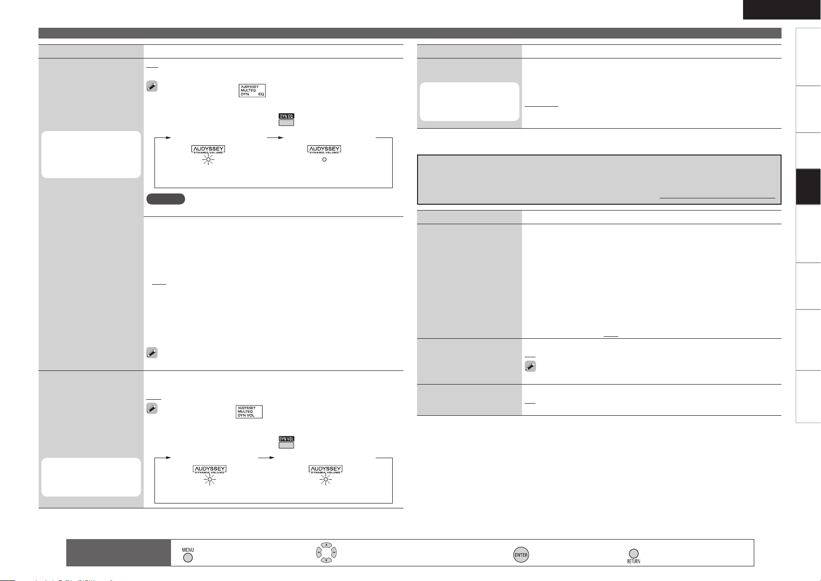
ENGLISH
Dynamic EQ : ON/Volume : OFF
“Green” “OFF”
Dynamic EQ / Volume : OFF
Dynamic EQ / Volume : ON
“Green” “Red”
Dynamic EQ : ON / Volume : OFF
Adjusting the Sound Field Effect (Parameter)
Getting Started
Setting items Setting contents
Dynamic EQ
Audyssey Dynamic EQ solves
the problem of deteriorating
sound quality as volume is
decreased by taking into
account human perception
and room acoustics.
This can be set when the
“MultEQ” (vpage 41)
is set to anything other
than “OFF”.
ON : Use Dynamic EQ function.
OFF : Do not use Dynamic EQ function.
• When set to “ON”, “ ” is displayed.
• When “MultEQ” is set to “OFF”, “Dynamic EQ” is automatically set
to “OFF”
• This can also be set by pressing .
“Red” “Off”
NOTE
“Tone Control” is set to “OFF” when “Dynamic EQ” is set to “ON”.
Reference Level Offset : Audyssey Dynamic EQ takes the standard film
mixing level of 85 dB SPL during –20 dB FS input as its reference level.
However, since standardization is lacking outside the film industry, the
reference level of media contents may not be appropriate. In order to
view such contents, Reference Level Offset of Dynamic EQ has available
offsets of 5 dB, 10 dB and 15 dB.
0dB : Suitable for viewing movies.
•
5dB : Suitable for listening to classical music and other content mixed
•
at a high level.
10dB : Suitable for listening to jazz and other audio sources with a wide
•
dynamic range. Also suitable for viewing TV.
15dB : Suitable for listening to pop, rock music and other content with an
•
extremely wide dynamic range.
Setting is enabled when “Dynamic EQ” is “ON”.
Dynamic Volume
Audyssey Dynamic Volume
solves the problem of
large variations in volume
level between television
programs, commercials, and
between the soft and loud
passages of movies.
ON : Use Dynamic Volume. The Dynamic Volume effect will be at the level
of the “Setting” (vpage 42)
OFF : Do not use Dynamic Volume.
• When set to “ON”, “ ” is displayed.
• When “MultEQ” is set to “OFF”, “Dynamic Volume” is automatically
set to “OFF”.
• This can also be set by pressing .
Setting items Setting contents
Setting
Set Dynamic Volume effect.
This can be set when
“Dynamic EQ” (vpage
42) is set to “ON”.
Day : Low setting provides the least adjustments to the loudest and
softest of sounds.
Evening : Middle setting prevents loud and soft sounds from being much
louder and softer respectively than average sounds.
Midnight : High setting affects volume the most, causing all sounds to be
of equal loudness.
Adjust tonal quality for each speaker using graphic equalizer
(Manual EQ)
Default settings are underlined.
Setting items Setting contents
Adjust CH
Adjust the tonal quality of
the individual speakers.
Base Curve Copy
Copy the MultEQ “Audyssey
Flat” correction curve.
Default
Reset the “Manual EQ”
settings to their defaults.
1. Select speaker adjustment method.
All CH : Adjust tonal quality for all speakers together.
L/R CH : Adjust tonal quality for each L/R speaker pair.
Each CH : Adjust tonal quality for each speaker separately.
2. Select the frequency band to be adjusted.
63Hz / 125Hz / 250Hz / 500Hz / 1kHz / 2kHz / 4kHz / 8kHz /
16kHz
b When “L/R CH” or “Each CH” is selected, select the speaker to be
adjusted.
3. Adjust the level.
–20.0dB ~ +6.0dB (0dB)
Yes : Copy.
No : Do not copy.
“Base Curve Copy” is displayed after the Audyssey Auto Setup
procedure has been performed.
Yes : Reset to the defaults.
No : Do not reset to the defaults.
Connections Remote Control Information Troubleshooting
Settings
Playback
Specifications
This can be set when
“Dynamic EQ” (vpage
42) is set to “ON”.
Remote control
operation buttons
“Green” “Red”
Displaying the menu
:
Cancel the menu
: Moves the cursor (Up/Down/Left/Right)
: Decision the setting
: Return to previous menu
Page 46

ENGLISH
OFF Mode 1
(RESTORER 64)
Mode 2
(RESTORER 96)
Mode 3
(RESTORER HQ)
Getting Started Connections Remote Control Information Troubleshooting Specifications
Adjusting the Sound Field Effect (Parameter)
Restoring compressed audio to nearly pre-compressed
conditions for playback (RESTORER)
Default settings are underlined.
• Such compressed audio formats as MP3, WMA (Windows Media Audio) and MPEG-4 AAC reduce the
amount of data by eliminating signal components that are hard for the human ear to hear. The RESTORER
function generates the signals eliminated upon compression, restoring the sound to conditions near
Settings
Playback
those of the original sound before compression. It also corrects the sense of volume of the bass to obtain
richer sound with compressed audio signals.
• This can be set with analog signals or when a PCM signal (fs = 44.1/48 kHz) is input.
Setting contents
OFF : Do not use RESTORER.
Mode1 (RESTORER 64) : Optimized mode for compressed sources with very weak highs.
Mode2 (RESTORER 96) : Apply suitable bass and treble boost for all compressed sources.
Mode3 (RESTORER HQ) : Optimized mode for compressed sources with normal highs.
• The default setting for “iPod” is “Mode3”. All others are set to “OFF”.
• When set to something other than “OFF”, “ ” is displayed.
• This can also be set by pressing during playback.
Adjusting the audio delay time while watching the picture
(Audio Delay)
Default settings are underlined.
Checking the Status (Information)
Setting items Setting contents
Status
Shows information about
current settings.
Audio Input Signal
Shows information about
audio input signals.
HDMI Information
Shows information about
HDMI input signals and
monitor.
Auto Surround Mode
Shows information about
auto surround mode
settings.
Quick Select
Shows information about
quick select settings.
Preset Channel
Shows information about
preset channels.
Select Source / Surround Mode / Input Mode / Decode Mode / HDMI
/ Digital / Component / iPod Dock / Video Select / Source Level
You can also display current status on the main unit’s display each time
you press .
Surround Mode : The currently set surround mode is displayed.
Signal : The input signal type is displayed.
fs : The input signal’s sampling frequency is displayed.
Format : The number of channels in the input signal (front, surround, LFE)
is displayed.
Offset : The dialogue normalization correction value is displayed.
Flag : This is displayed when inputting signals including a surround back
channel. “MATRIX” is displayed with Dolby Digital EX and DTS-ES Matrix
signals, “DISCRETE” with DTS-ES Discrete signals.
HDMI Signal Information
Resolution / Color Space / Pixel Depth •
HDMI Monitor Information
Interface / Suport Resolution •
Analog/PCM / Digital 2ch / Digital 5.1ch / Multi CH
Quick Select 1 / Quick Select 2 / Quick Select 3
Name / Input Source / Video Select / Volume Level / MultEQ /
•
Dynamic EQ / Dynamic Vol / Analog/PCM / Digital 2ch / Digital
5.1ch / Multi CH
A 1 ~ G 8
TUNER•
Setting contents
0ms ~ 200ms
• If you wish to adjust the “Audio Delay” while playing HDMI or component video signals, press u
to set “OSD” to “OFF”. This way the audio delay can be adjusted while watching the picture. (Press
the u again. The display switches to the display of the menu screen only.)
• This cannot be adjusted when playing in the DIRECT or STEREO mode (with “Front Speaker” set to
“Large”, “Tone Control” to “OFF” and “MultEQ” and “RESTORER” to “OFF”).
• When the Auto Lipsync Correction function is operating, you can set within the range 0 ~ 100 ms.
• Store “Audio Delay” for each input source.
Remote control
operation buttons
Displaying the menu
:
Cancel the menu
: Moves the cursor (Up/Down/Left/Right)
: Decision the setting
: Return to previous menu
Page 47

Convenient functions
Sleep:OFF Sleep:120min
Sleep:30min Sleep:60min
Sleep:90min
ENGLISH
Getting Started
HDMI Control Function
When you make an HDMI connection with a TV or player
compatible with AVR-590 and HDMI control functions, you can
perform the following operations by setting the HDMI control
function of each device.
n AVR-590 power off can be linked to the TV power
off step
zWhen you set “Output audio from amp” in the TV audio
output setup operation, you can switch the amp power
on.
n You can switch audio output devices with a TV
operation
n You can adjust AVR-590 volume in the TV volume
adjustment operation
n You can switch AVR-590 input source through
linkage to TV input switching
n When playing the player, the AVR-590 input
function switches to the function of that player
• To play the TV’s sound on the AVR-590, make optical digital
connections (vpage 13 “Connecting the TV”).
• To use this function, set “HDMI Control” (vpage 27) to “ON”.
NOTE
• When you power off AVR-590, the HDMI control function does not
operate.
• Some functions may not operate depending on the connected
TV or player. Check the owner’s manual of each device for details
beforehand.
• When “HDMI Control” is set to “ON”, it is not possible to assign an
HDMI connector to “TV” at “HDMI” (vpage 27).
Turn the power on for all the equipment connected by
1
HDMI cable.
Set the HDMI control function for all equipment
2
connected by HDMI cable.
Set “HDMI Control” (vpage 27) to “ON“.
b Please refer to the owner’s manual as regards setting of connected
devices.
b Carry out Steps 1 and 2 should any of the equipment be
unplugged.
Switch the television input to the HDMI connected to
3
the AVR-590.
Switch the AVR-590 input to the HDMI input source
4
and check if the picture from the player is ok.
When you turn the TV’s power to standby, check that
5
the power of the AVR-590 and player also goes on
standby.
If the HDMI control function does not operate properly, check the
following points.
• Is the TV or player compatible with the HDMI control function?
• Is the AVR-590 properly set?
• Is “HDMI Control” (vpage 27) set to “ON”?
• Is “Power Off Control” (vpage 27) set to “ON”?
• Are the HDMI control function settings of all equipment correct?
NOTE
Should any of the operations below be performed, the interlocking
function may be reset, in which case, repeat step’s 1 and 2.
Menu “HDMI” (vpage 27) setting has changed.
•
There is a change to the connection between the equipment and the
•
HDMI, or an increase in equipment.
Setting the power to standby
after a certain amount of time
(Sleep Timer Function)
This function allows you to automatically set the power to
standby after the set amount of time has passed.
Press and display the time you want to set.
The “SLEEP” indicator on the display lights.
• The time switches as shown below each time is pressed.
• The time display turns off after about 5 seconds, and the
setting is activated.
• Once the set time has passed, the power is automatically set
to standby.
n To cancel the sleep timer
Press to set “OFF”.
• The “SLEEP” indicator on the display turns
off.
Playing the picture of a different
input source without changing
the currently playing sound
(Video Select Function)
Switch video input source while listening to audio signal.
Press until the desired picture
appears.
b To cancel, press to select “SOURCE”.
NOTE
It is not possible to select HDMI input signals.
•
When playing HDMI video input signals, the analog video signal of
•
another input source cannot be selected for the HDMI video output.
Input sources for which “Delete” is selected at “Source Delete”
•
(vpage 28) cannot be selected.
Input sources for which “None” is selected at “Assign” (vpage 31)
•
cannot be selected.
Connections Remote Control Information Troubleshooting
Playback
SpecificationsSettings
Page 48
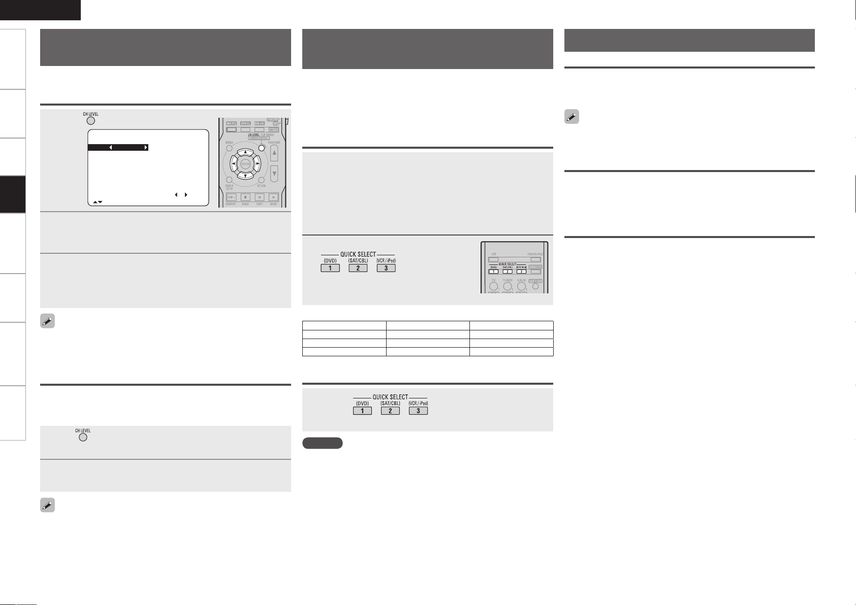
ENGLISH
Channel Volume
FL 0.0dB SR 0.0dB
C 0.0dB SBR 0.0dB
FR 0.0dB SBL 0.0dB
SW 0.0dB SL 0.0dB
Fader
FRONT : REAR
[ ]:CH Sel.
Getting Started Connections Remote Control Information Troubleshooting SpecificationsSettings
Adjust the volume of the
different speakers
You can adjust the channel level either according to the playback
sources or to suit your taste, as described below.
Adjust the volume of the different speakers
Press .
1
Saving frequently used settings
(Quick Select Function)
This function allows you to save all the settings shown in step
1. When frequently used settings are saved, they can easily be
set again the next time you want to use them. This function also
allows you to always enjoy the same playback environment.
• Three sets of settings can be saved.
Saving the settings
Various memory functions
Personal Memory Plus Function
This function sets the settings (input mode, surround mode, HDMI
output mode, MultEQ, Dynamic EQ, Dynamic Volume, audio delay
etc.) last selected for the individual input sources.
The surround parameters, tone settings and the volumes of the
different speakers are stored for the individual surround modes.
Playback
Press ui to select the speaker.
The speaker that can be set switches each time one of the
2
buttons is pressed.
Press o p to adjust the volume.
3
b In the case of a subwoofer, reducing the volume when it is at
“–12 dB” will change the setting to “OFF” (none).
If headphones are plugged in, the headphones settings screen
appears.
Adjusting the volume of groups of speakers
(Fader Function)
This function lets you adjust (fade) the sound from all the front (Front
speaker / center speaker / Front Height speaker) or rear (Surround speaker /
Surround Back speaker) speakers at once.
Use or i to select “Fader”, then select the item to
1
be adjusting using o or p.
Press o p to adjust the volume of the speakers.
2
• The fader function does not affect the subwoofer.
• The fader can be adjusted until the volume of the speaker adjusted
to the lowest value is –12 dB.
Set the items below to the settings you want to save.
1
q Input source (vpage 34)
w Input Mode (vpage 32)
e Surround Mode (vpage 37)
r Audyssey Settings (MultEQ, Dynamic EQ, Dynamic
Volume) (vpage 41)
t Volume setting (vpage 34)
Press and hold the desired
2
until “Memory”
appears on the display.
The current settings will be memorized.
GQuick Select DefaultsH
Quick Select 1 DVD –40 dB
Quick Select 2 SAT/CBL –40 dB
Quick Select 3 VCR/iPod –40 dB
Calling the settings out
Press the at which the settings you
want to call out are saved.
NOTE
Input sources stored with the quick select function cannot be selected
if they have been deleted at menu “Source Delete” (vpage 28). In
this case, store them again.
n Naming Quick Select settings
“Quick Select Name” (vpage 29).
Input Source Volume
Last Function Memory
This stores the settings as they were directly before the standby mode
was set.
When the power is turned back on, the settings are restored to as they
were directly before the standby mode was set.
Backup Memory
The various settings are backed up for about 1 week, even if the power
is turned off or the power cord is disconnected.
Page 49

Operating the Connected Devices by Remote Control Unit
ENGLISH
Getting Started
Registering Preset Codes
DENON and other makes of components can be operated by
setting the preset memory.
n Cautions during operation
When registering a preset code, point the remote control transmitter
toward the AVR-590. The status of the registration operation is
displayed on the AVR-590.
Press the source select button (see
1
below) for the device to be registered
and simultaneously for over 2
seconds.
“RC SETUP START” appears on the display
and the remote control unit is set to the
preset code registration mode.
: TV : Digital video recorder
DVD player
:
or CD player
: Blu-ray disc player
Press ~ and input the
2
3-digit number of the brand of
the component to be preset. The
numbers are shown in the Preset
Code Table (vEnd of this
manual).
When registration is completed, “RC SETUP OK” appears on
the display.
b If the codes could not be registered, “RC SETUP NG” appears on
the display. Try again.
: Video deck
Satellite receiver
:
or cable TV
Operating Registered Devices
Switch to the device to be operated.
1
TUNER/AMP
DEVICE
MAIN/TV
When “DEVICE” has been selected in step 1, press
2
the source select button for the device to be operated.
The remote control unit is set to the device mode for the device
to be operated. When the remote control transmitter is pointed
towards the AVR-590 at this time, the AVR-590’s input source
switches simultaneously.
b The remote control unit stays in the same device mode until a
different source select button is pressed.
Operate the component.
: To operate a Tuner
: To operate a Blu-ray disc player, DVD player,
CD player,
iPod, Satellite receiver or cable TV
: To operate a TV
Digital video recorder, Video deck,
3
b For details, refer to the component’s operating instructions.
NOTE
Depending on the model and year of manufacture, this function cannot
be used for some models, even if they are of makes listed in the list
of preset codes.
iPod
Operating Registered Devices
Operation
mode setting
ON/SOURCE
1
2
3
MEMORY
TOP MENU
6 7
8 9
uio p
ENTER Enter
SEARCH
RETURN Return
PAGE d f
z
1 : This operation is possible when using a
DENON ASD-3N or ASD-3W Control Dock
for iPod.
z
2 : This operation is possible when using a
DENON ASD-1R or ASD-11R Control Dock
for iPod.
Power on / Standbyz1
Play / Pause
Stop
Pause
MEMORY z1
Calling out the top menus z1
Manual search
(fast-reverse / fast-forward)
Auto search
(cue)
Cursor
Press and
hold
Browse/Remote
mode switching
Page up/downz1
Once
Page search
mode switching
z
2
Connections Playback Information Troubleshooting
Remote Control
SpecificationsSettings
To store the codes of another component in the
3
memory, repeat steps 1 to 2.
b For details, refer to the component’s operating instructions.
• Some manufacturers use more than one type of remote control code.
Refer to the included list of preset codes to change the number and
verify correct operation.
• The preset memory can be set for one component only among the
following: DVD/CD and SAT/CBL.
Page 50

ENGLISH
Getting Started Connections Playback Information Troubleshooting SpecificationsSettings
TV
Blu-ray Disc / DVD Player
Operating Registered Devices
CD Player
Operation
mode setting
ON/SOURCE Power on / Standby
TV/POWER
1 Play z2
3 Pause z2
2 Stop z2
6 7
CHANNEL + –
Remote Control
TV INPUT
VOLUME df
MUTE TV MUTE
MENU Calling out the menus
uio p
ENTER Enter setting
SETUP Setup
RETURN Return
Defau
lt setting
(Preset code)
Special Remarks
*1 : This can be operated even when the
operation mode is set to something
other than “TV”.
*2 : When the punch through function
(vpage 48) is set, this functions
as the button for the device for which
punch through is set.
Power on / Standby z1
Manual search z2
(fast-reverse / fast-forward)
Switch channels (+, –)
Switching the input z1
d : TV Volume (+)
f : TV Volume (–)
Cursor operation
SONY
(374)
q
Operation
mode setting
OFF Standby
ON/SOURCE
1
2
3
SKIP +
6 7
8 9
MENU
uio p
ENTER Enter setting
SETUP Setup
RETURN Return
TOP MENU Top menus
Defau
lt setting
(Preset code)
Special Remarks
Power on or Power on / Standby
BD Player DVD Player
– Disc skip
Manual search
(fast-reverse / fast-forward)
Auto search (cue)
BD Player DVD Player
Popup menus Menus
Cursor operation
BD Player DVD Player
DENON (111) DENON (111)
or
Play
Stop
Pause
q, w
Operation
mode setting
OFF Standby
ON/SOURCE
1
2
3
SKIP + Disc skip +
6 7
8 9
Defau
lt setting
(Preset code)
Special Remarks
Power on or Power on /
(fast-reverse / fast-forward)
Standby
Play
Stop
Pause
Manual search
Auto search (cue)
–
q
【Special Remarks】
q Only one device can be set in the preset memory for each mode.
When a new preset code is registered, the existing code is automatically erased.
w For some brands, the DVD remote control buttons may have different function names.
Check beforehand.
Page 51

Digital Video Recorder / Video Deck
Satellite receiver/Cable TV
Operation
mode
setting
ON/SOURCE Power on / Standby
1
2
3
6 7
CHANNEL + –
MENU Menus
uio p
ENTER Enter setting
SETUP Setup
RETURN Return
Defau
lt setting
(Preset code)
Special Remarks
【Special Remarks】
q Only one device can be set in the preset memory for each mode.
When a new preset code is registered, the existing code is automatically erased.
w For some brands, the DVD remote control buttons may have different function names.
Check beforehand.
(fast-reverse / fast-forward)
Digital Video
Recorder
Play
Stop
Pause
Manual search
Switch
channels (+, –)
Cursor operation
JVC
(001)
q, w
Video Deck
HITACHI
or
(111)
Operating Registered Devices
Operation
mode setting
ON/SOURCE Power on / Standby
1 Play
3 Pause
2 Stop
6 7
CHANNEL + –
uio p
ENTER Enter setting
MENU
SETUP
RETURN Return
Defau
lt setting
(Preset code)
Special Remarks
* : When the punch through function
(vpage 48) is set, this functions as the
button for the device for which punch
through is set.
(fast-reverse / fast-forward)
Switch
Satellite
Receiver
Direc TV
(095)
z
z
z
Manual search
channels (+, –)
Cursor operation
Guide menus
Setup
Cable TV
q
z
–
ENGLISH
Assigning buttons that are Not
Used to Operate Other Devices
(Punch Through Function)
When the remote control unit´s device mode is set to “TV” or “SAT/
CBL”, the next “TUNER”, “DVD”, “HDP”, “iPod”, “DVR” or “VCR”
operation can be performed without switching the remote control
unit's device mode.
• One device each can be assigned to the “TV” and “SAT/CBL”
device modes.
•Assignable buttons
n Cautions during operation
When registering a punch through function, point the remote control
transmitter toward the AVR-590. The status of the registration operation
is displayed on the AVR-590.
Press or for the device
1
for which the punch through
function is to be registered and
simultaneously for over 2 seconds.
“RC SETUP START” appears on the
display.
Press the source select button for
2
the device to be assigned.
When registration is completed, “RC
SETUP OK” appears on the display.
b If the codes could not be registered, “RC
SETUP NG” appears on the display. Try
again.
Getting Started
Connections Playback Information Troubleshooting
Remote Control
SpecificationsSettings
NOTE
If the “TV” or “SAT/CBL” preset code is changed after setting the
punch through function, the punch through setting is canceled.
Page 52
ENGLISH
Getting Started Connections Playback Remote Control Troubleshooting SpecificationsSettings
Other Information
Surround
The AVR-590 is equipped with a digital signal processing circuit that lets you play program sources in the surround mode to achieve the same sense of presence as in a movie theater.
Dolby Surround
Dolby Digital
Dolby Digital is a multichannel digital signal format developed by Dolby
Laboratories.
A total of 5.1-channels are played: 3 front channels (“FL” , “FR” and
“C”), 2 surround channels (“SL” and “SR”) and the “LFE” channel for
low frequencies.
Because of this, there is no crosstalk between channels and a realistic
sound field with a “three-dimensional” feeling (sense of distance,
movement and positioning) is achieved.
A real, overpowering sense of presence is achieved when playing
movie sources in AV rooms as well.
Information
Dolby Digital Plus
Dolby Digital Plus is an improved Dolby Digital signal format that is
compatible with up to 7.1-channels of discrete digital sound and also
improves sound quality thanks to extra data bit rate performance. It
is upwardly compatible with conventional Dolby Digital, so it offers
greater flexibility in response to the source signal and the conditions
of the playback equipment.
Dolby TrueHD
Dolby TrueHD is a high definition audio technology developed by Dolby
Laboratories, using lossless coding technology to faithfully reproduce
the sound of the studio master.
This format is compatible with a maximum sampling frequency of 96
kHz and up to 7.1-channels, so it is used for applications particularly
prioritizing sound quality.
Dolby Pro Logic g
Dolby Pro Logic g is a matrix decoding technology developed by Dolby
Laboratories.
Regular music such as that on CDs is encoded into 5-channels to
achieve an excellent surround effect.
The surround channel signals are converted into stereo and full band
signals (with a frequency response of 20 Hz to 20 kHz or greater)
to create a “three-dimensional” sound image offering a rich sense of
presence for all stereo sources.
Dolby Pro Logic gx
Dolby Pro Logic gx is a further improved version of the Dolby Pro Logic
g matrix decoding technology.
Audio signals recorded in 2-channels are decoded to achieve a natural
sound with up to 7.1-channels.
There are 3 modes: “Music” suited for playing music, “Cinema”
suited for playing movies, and “Game” which is optimized for playing
games.
Dolby Digital EX
Dolby Digital EX is a 6.1-channel surround format proposed by Dolby
Laboratories that allows users to enjoy in their homes the “DOLBY
DIGITAL SURROUND EX” audio format jointly developed by Dolby
Laboratories and Lucas Films.
The 6.1 channels of sound, including surround back channels, provide
improved sound positioning and expression of space.
Dolby Pro Logic gz
Dolby Pro Logic gz introduces a new dimension to Home Entertainment
through the addition of a pair of front height channels. Compatible with
stereo, 5.1 and 7.1 content, Dolby Pro Logic gz provides enhanced
spaciousness, depth and dimension to movies, concert video and
videogame playback while maintaining the full integrity of the source
mix.
Dolby Pro Logic gz identifies and decodes spatial cues that occur
naturally in all content, directing this information to the front height
channels, complementing the performance of left and right surround
sound speakers. Content that is encoded with Dolby Pro Logic
gz height channel information can be even more revealing, with
perceptually discrete height channel information bringing an exciting
new dimension to home entertainment.Dolby Pro Logic gz, with front
height channels is also an ideal alternative for households that cannot
support the placement of back surround speakers of a typical 7.1
channel system but may have bookshelf space available to support the
addition of height speakers.
Manufactured under license from Dolby Laboratories.
“Dolby”, “Pro Logic” and the double-D symbol are trademarks of
Dolby Laboratories.
DTS Surround
DTS Digital Surround
DTS Digital Surround is the standard digital surround format of DTS,
Inc., compatible with a sampling frequency of 44.1 or 48 kHz and up
to 5.1-channels of digital discrete surround sound.
DTS-HD High Resolution Audio
DTS-HD High Resolution Audio is an improved version of the
conventional DTS, DTS-ES and DTS 96/24 signals formats, compatible
with sampling frequencies of 96 or 48 kHz and up to 7.1-channels
of discrete digital sound. High data bit rate performance provides
high quality sound. This format is fully compatible with conventional
products, including conventional DTS digital surround 5.1-channel
data.
DTS-HD Master Audio
DTS-HD Master Audio is DTS, Inc’s lossless audio format compatible
with up to 96 kHz/7.1-channels. The lossless audio coding technology
faithfully reproduces the sound of the studio master. It is fully
compatible with conventional products, including conventional DTS
digital surround 5.1-channel data.
DTS-ES™ Discrete 6.1
DTS-ES™ Discrete 6.1 is a 6.1-channel discrete digital audio format
adding a surround back (SB) channel to the DTS digital surround sound.
Decoding of conventional 5.1-channel audio signals is also possible
according to the decoder.
DTS-ES™ Matrix 6.1
DTS-ES™ Matrix 6.1 is a 6.1-channel discrete digital audio format
inserting a surround back (SB) channel to the DTS digital surround
sound through matrix encoding. Decoding of conventional 5.1-channel
audio signals is also possible according to the decoder.
DTS NEO:6™ Surround
DTS NEO:6™ is a matrix decoding technology for achieving 6.1channel surround playback with 2-channel sources. It includes “DTS
NEO:6 Cinema” suited for playing movies and “DTS NEO:6 Music”
uited for playing music.
Page 53
DTS 96/24
DTS 96/24 is a digital audio format enabling high sound quality
playback in 5.1-channels with a sampling frequency of 96 kHz and 24
bit quantization on DVD-Video.
Manufactured under license under U.S. Patent #’s: 5,451,942;
5,956,674; 5,974,380; 5,978,762; 6,226,616; 6,487,535; 7,212,872;
7,333,929; 7,392,195; 7,272,567 & other U.S. and worldwide patents
issued & pending. DTS is a registered trademark and the DTS
logos, Symbol, DTS-HD and DTS-HD Master Audio are trademarks
of DTS, Inc.© 1996-2008 DTS, Inc. All Rights Reserved.
Audyssey
Audyssey MultEQ®
Audyssey MultEQ is a room equalization solution that calibrates any
audio system so that it can achieve optimum performance for every
listener in a large listening area. Based on several room measurements,
MultEQ calculates an equalization solution that corrects for both
time and frequency response problems in the listening area and also
performs a fully automated surround system setup.
Audyssey Dynamic Volume™
Audyssey Dynamic Volume solves the problem of large variations in
volume level between television programs, commercials, and between
the soft and loud passages of movies.
Audyssey Dynamic EQ is integrated into Dynamic Volume so that as
the playback volume is adjusted automatically, the perceived bass
response, tonal balance, surround impression, and dialog clarity
remain the same.
Manufactured under license from Audyssey Laboratories. U.S.
and foreign patents pending. Audyssey MultEQ® is a registered
trademark of Audyssey Laboratories. Audyssey Dynamic EQ™ is a
trademark of Audyssey Laboratories. Audyssey Dynamic Volume™
is a trademark of Audyssey Laboratories.
ENGLISH
Surround
Getting Started
Connections Playback Remote Control Troubleshooting
Information
Audyssey Dynamic EQ™
Audyssey Dynamic EQ solves the problem of deteriorating sound
quality as volume is decreased by taking into account human perception
and room acoustics. Audyssey Dynamic EQ works in tandem with
Audyssey MultEQ to provide well-balanced sound for every listener
at any volume level.
SpecificationsSettings
0
Page 54
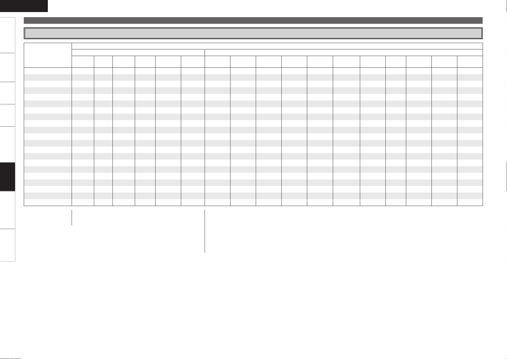
ENGLISH
Getting Started Connections Playback Remote Control Troubleshooting SpecificationsSettings
Surround Modes and Parameters
Signals and adjustability in the different modes
Surround mode
Front L/R Center
DIRECT
MULTI CH DIRECT
STEREO
MULTI CH IN
DOLBY PRO LOGIC gx S D D D A D S (OFF) A A S S (NOTE1) S (Cinema) A A A A S (Auto)
DOLBY PRO LOGIC g S D D A A D S (OFF) A A S S (NOTE2) S (Cinema) A A A A S (Auto)
DTS NEO:6
DOLBY PRO LOGIC gz S D D A D D S (OFF) A A A S (OFF) A A A A A A
DOLBY DIGITAL
DOLBY DIGITAL Plus
DOLBY TrueHD
DTS SURROUND
DTS 96/24
DTS-HD
5CH/7CH STEREO
Information
ROCK ARENA
JAZZ CLUB
MONO MOVIE
VIDEO GAME
MATRIX
VIRTUAL
S D D D A D S (OFF) S (0dB) A A A A A A A S S (Auto)
S D D D A D A S (0dB) S (ON) S A A A A A A A
S A A A A D S (OFF) S (0dB) A A A A A A A A S (Auto)
S D D D A D A S (0dB) S (ON) S A A A A A A A
S D D D A D S (OFF) A A S S (NOTE1) S (Cinema) A A A A A
S D D D D D S (OFF) S (0dB) S (ON) S S (OFF) A A A A A A
S D D D D D S (OFF) S (0dB) S (ON) S S (OFF) A A A A A A
S D D D D D S (OFF) S (0dB) S (ON) S S (OFF) A A A A A S (Auto)
S D D D D D S (OFF) S (0dB) S (ON) S S (OFF) A A A A A A
S D D D D D S (OFF) S (0dB) S (ON) S S (OFF) A A A A A A
S D D D D D S (OFF) S (0dB) S (ON) S S (OFF) A A A A A A
S D D D D D S (OFF) S (0dB) A S A A A A A A A
S D D D D D S (OFF) S (0dB) A S A A
S D D D D D S (OFF) S (0dB) A S A A
S D D D D D S (OFF) S (0dB) A S A A
S D D D D D S (OFF) S (0dB) A S A A
S D D D D D S (OFF) S (0dB) A S A A A A S (30 ms) A A
S A A A A D S (OFF) S ( 0dB) A A A A A A A A A
S : Signal / Adjustable
A : No signal / Not adjustable
D : Turned on or off by speaker configuration setting
Channel output Parameter (default values are shown in parentheses)
Surround
L/R
Surround
Back L/R
Front Height
L/R
Subwoofer
D. Comp
S : Signal / Adjustable
A : No signal / Not adjustable
NOTE1 : This parameter is available when the menu “Mode” (vpage 39) is set to “Cinema”.
NOTE2 : This parameter is available when the menu “Mode” (vpage 39) is set to “Cinema” or “PL”.
NOTE:
z
1 : When playing Dolby Digital and DTS signals.
z
2 : When playing Dolby Digital, DTS and Linear PCM (multi ch).
z
3 : When playing Dolby TrueHD signal.
LFE
z
1
AFDM
z
2
SB CH Out Cinema EQ. Mode Room Size Effect Delay time Subwoofer
z
1
S (Medium)
S (Medium)
S (Medium)
S (Medium)
S (10) A A A
S (10) A A A
S (10) A A A
S (10) A A A
Surround
DRC
z
3
Page 55
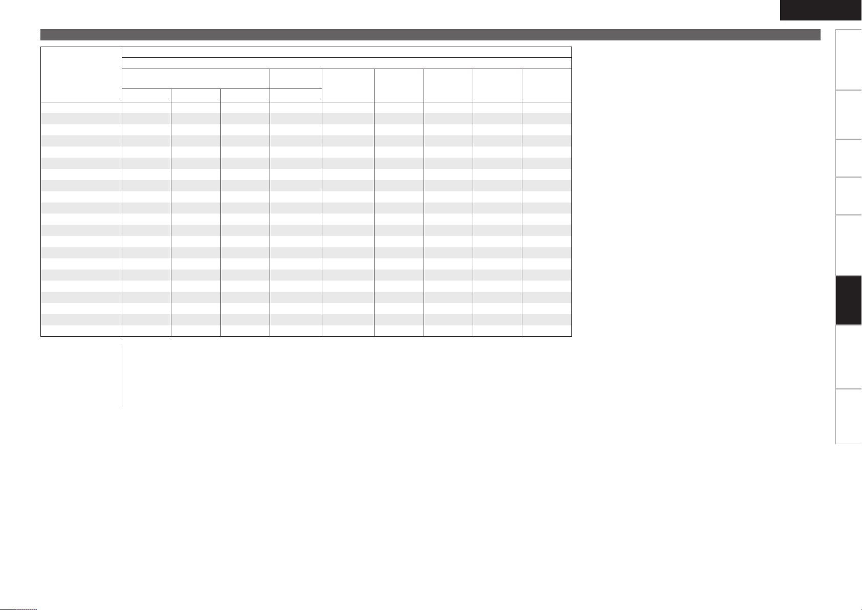
Signals and adjustability in the different modes
Parameter (default values are shown in parentheses)
Surround mode
DIRECT
MULTI CH DIRECT
STEREO
MULTI CH IN
DOLBY PRO LOGIC gx S (OFF) S (3) S (3) A S (0dB) S (OFF) S (OFF) S (OFF) S
DOLBY PRO LOGIC g S (OFF) S (3) S (3) A S (0dB) S (OFF) S (OFF) S (OFF) S
DTS NEO:6
DOLBY PRO LOGIC gz A A A A S (0dB) S (OFF) S (OFF) S (OFF) A
DOLBY DIGITAL
DOLBY DIGITAL Plus
DOLBY TrueHD
DTS SURROUND
DTS-96/24
DTS-HD
5CH/7CH STEREO
ROCK ARENA
JAZZ CLUB
MONO MOVIE
VIDEO GAME
MATRIX
VIRTUAL
PRO LOGIC g/gx MUSIC mode only
Panorama Dimension C. Width Center Image
A A A A A A A A A
A A A A A A A A A
A A A A S (0dB) S (OFF) S (OFF) S (OFF) S
A A A A S (0dB) S (OFF) S (OFF) S (OFF) A
A A A S (0.3) S (0dB) S (OFF) S (OFF) S (OFF) S
A A A A S (0dB) S (OFF) S (OFF) S (OFF) A
A A A A S (0dB) S (OFF) S (OFF) S (OFF) A
A A A A S (0dB) S (OFF) S (OFF) S (OFF) A
A A A A S (0dB) S (OFF) S (OFF) S (OFF) A
A A A A S (0dB) S (OFF) S (OFF) S (OFF) A
A A A A S (0dB) S (OFF) S (OFF) S (OFF) A
A A A A S (0dB) S (OFF) S (OFF) S (OFF) S
A A A A S (NOTE3) S (OFF) S (OFF) S (OFF) S
A A A A S (0dB) S (OFF) S (OFF) S (OFF) S
A A A A S (0dB) S (OFF) S (OFF) S (OFF) S
A A A A S (0dB) S (OFF) S (OFF) S (OFF) S
A A A A S (0dB) S (OFF) S (OFF) S (OFF) S
A A A A S (0dB) S (OFF) S (OFF) S (OFF) S
S : Adjustable
A : Not adjustable
NOTE3 : BASS +6 dB, TREBLE +4 dB
NOTE4 : Cannot be set when the “Dynamic EQ” (vpage 42) setting is “ON”.
NOTE5 : Cannot be set when the “MultEQ” (vpage 41) setting is “OFF”.
NOTE6 : Cannot be set when the “Dynamic EQ” (vpage 42) setting is “OFF”.
NOTE7 : “RESTORER” can be set for analog or PCM 48 k or 44.1 k input signals.
NEO:6 MUSIC
mode only
Tone
(NOTE4)
MultEQ
Dynamic EQ
(NOTE5)
Dynamic
Volume
(NOTE6)
RESTORER
(NOTE7)
ENGLISH
Surround
Getting Started
Connections Playback Remote Control Troubleshooting
Information
SpecificationsSettings
Page 56
ENGLISH
Getting Started Connections Playback Remote Control Troubleshooting SpecificationsSettings
Differences in Surround Mode Names Depending on the Input Signals
Surround
Information
Button
Input signals
PCM DTS-HD DTS DOLBY DOLBY DIGITAL
Surround mode
Note
ANALOG
Linear
PCM
(multi ch)
Linear
PCM
(2ch)
DTS-HD
Master
Audio
DTS-HD
High
Resolution
Audio
DTS ES
DSCRT
(With Flag)
DTS ES
MTRX
(With Flag)
DTS
(5.1ch)
DTS
96/24
DOLBY
TrueHD
DOLBY
DIGITAL
Plus
DOLBY
DIGITAL
EX (With
Flag)
DOLBY
DIGITAL EX
(With no
Flag)
DOLBY
DIGITAL
(5.1/5/4ch)
STANDARD
DTS SURROUND
DTS-HD MSTR
DTS-HD HI RES
DTS ES DSCRT6.1
DTS ES MTRX6.1
DTS SURROUND
DTS 96/24
DTS (–HD) + PLgx CINEMA
DTS (–HD) + PLgx MUSIC
DTS (–HD) + PLgz
DTS (–HD) + NEO:6
DTS NEO:6 CINEMA
DTS NEO:6 MUSIC
z1 z
z1 z
z2 z
z1 z
z1 z
z1 z
A A A F A A A A A A A A A A A A
A A A A F A A A A A A A A A A A
3
A A A A A F D A A A A A A A A A A
3
A A A A A A F D A A A A A A A A A
A A A A A S S F A A A A A A A A
A A A A A A A A F A A A A A A A
3
A A A S S S S S S A A A A A A A
3
A A A S S S S S S A A A A A A A
4
A A A S S S S S S A A A A A A A
3
A A A S S A S S S A A A A A A A
S A S A A A A A A A A A A A A S
S A S A A A A A A A A A A A A S
DOLBY SURROUND
DOLBY TrueHD
DOLBY DIGITAL+
DOLBY DIGITAL EX
DOLBY (D+) (HD) +EX
DOLBY DIGITAL
DOLBY (D) (D+) (HD) +PLgx CINEMA
DOLBY (D) (D+) (HD) +PLgx MUSIC
DOLBY (D) (D+) (HD) +PLgz
DOLBY PRO LOGIC gx CINEMA
DOLBY PRO LOGIC gx MUSIC
DOLBY PRO LOGIC gx GAME
DOLBY PRO LOGIC g
z
z1 z
z1 z
z2 z
z1 z
z1 z
z
z
z
z
A A A A A A A A A F A A A A A A
A A A A A A A A A A F A A A A A
3
A A A A A A A A A A A S S S S A
3
A A A A A A A A A S S A A A A A
A A A A A A A A A A A S F F F A
3
A A A A A A A A A S S F D S S S A
3
A A A A A A A A A S S S S S S A
4
A A A A A A A A A S S S S S S A
3
S A S A A A A A A A A A A A A S
3
S A S A A A A A A A A A A A A S
3
S A S A A A A A A A A A A A A S
4
S A S A A A A A A A A A A A A S
DOLBY PRO LOGIC g CINEMA S A S A A A A A A A A A A A A S
DOLBY PRO LOGIC g MUSIC S A S A A A A A A A A A A A A S
DOLBY PRO LOGIC g GAME S A S A A A A A A A A A A A A S
DOLBY PRO LOGIC
NOTE:
z
1: This mode is not available when the surround back speaker setup is set to “None”.
z
2: This mode is not available when the surround back speaker setup is set to “1ch” or “None”.
z
3: Can be set when “Pre Assign” is set to “Normal”.
z
4: Not selectable when “Pre Assign” is set to anything other than “Front Height”.
S A S A A A A A A A A A A A A S
F : Mode selectable in initial status
D : Mode fixed when “AFDM” is “ON”
S : Selectable mode
A : Non-selectable mode
DOLBY
DIGITAL
(4/3ch)
DOLBY
DIGITAL
(2ch)
Page 57

Button
Surround mode
STANDARD
MULTI CH IN
MULTI CH IN
MULTI IN + PLgx CINEMA
MULTI IN + PLgx MUSIC
MULTI IN + PLgz
MULTI IN + Dolby EX
MULTI CH IN 7.1
DIRECT
DIRECT
MULTI CH DIRECT
M DIRECT + PLgx CINEMA
M DIRECT + PLgx MUSIC
M DIRECT + PLgz
M DIRECT + Dolby EX
M DIRECT 7.1
DSP SIMULATION
5CH/7CH STEREO
ROCK ARENA
JAZZ CLUB
MONO MOVIE
VIDEO GAME
MATRIX
VIRTUAL
STEREO
STEREO
PCM DTS-HD DTS DOLBY DOLBY DIGITAL
Note
ANALOG
Linear
PCM
(multi ch)
Linear
PCM
(2ch)
DTS-HD
Master
Audio
DTS-HD
High
Resolution
Audio
DTS ES
DSCRT
(With Flag)
DTS ES
MTRX
(With Flag)
A F A A A A A A A A A A A A A A
z2 z
3
z1 z
z1 z
z1 z
z
A S A A A A A A A A A A A A A A
3
A S A A A A A A A A A A A A A A
5
A S A A A A A A A A A A A A A A
3
A S A A A A A A A A A A A A A A
3
A F D (7.1) A A A A A A A A A A A A A A
S A S S S S S S S S S S S S S S
A S A A A A A A A A A A A A A A
z2 z
3
z1z
z1z
z1 z
z
z
A S A A A A A A A A A A A A A A
3
A S A A A A A A A A A A A A A A
5
A S A A A A A A A A A A A A A A
3
A S A A A A A A A A A A A A A A
3
A S (7.1) A A A A A A A A A A A A A A
4
S S S S S S S S S S S S S S S S
S S S S S S S S S S S S S S S S
S S S S S S S S S S S S S S S S
S S S S S S S S S S S S S S S S
S S S S S S S S S S S S S S S S
S S S S S S S S S S S S S S S S
S S S S S S S S S S S S S S S S
F S F S S S S S S S S S S S S S
NOTE :
z
1: This mode is not available when the surround back speaker setup is set to “None”.
z
2: This mode is not available when the surround back speaker setup is set to “1ch” or “None”.
z
3: Can be set when “Pre Assign” is set to “Normal”.
z
4: If the surround back speaker setup is set to “None”, then “5CH STEREO” is displayed.
z
5: Not selectable when “Pre Assign” is set to anything other than “Front Height”.
Input signals
DTS
(5.1ch)
DTS
96/24
DOLBY
TrueHD
DOLBY
DIGITAL
Plus
DIGITAL
EX (With
F : Mode selectable in initial status
D : Mode fixed when “AFDM” is “ON”
S : Selectable mode
A : Non-selectable mode
DOLBY
Flag)
DOLBY
DIGITAL
EX (With
no Flag)
DOLBY
DIGITAL
(5.1/5/4ch)
DOLBY
DIGITAL
(4/3ch)
ENGLISH
Surround
DOLBY
DIGITAL
(2ch)
Getting Started
Connections Playback Remote Control Troubleshooting
Information
SpecificationsSettings
Page 58
ENGLISH
Getting Started Connections Playback Remote Control Information Specifications
Troubleshooting
If a problem should arise, first check the following:
1. Are the connections correct?
2. Is the set being operated as described in the owner’s manual?
3. Are the other components operating properly?
If this unit does not operate properly, check the items listed in the table below. Should the problem persist,
there may be a malfunction.
Settings
In this case, disconnect the power immediately and contact your store of purchase.
GGeneralH
Symptom Cause Countermeasure Page
Set does not
operate properly.
Power does not
turn on, or turns
off directly after it
was turned on.
No sound is
produced from
speakers.
Troubleshooting
Display is off. • The “Display” setting is set to
“DOLBY DIGITAL”
indicator does not
appear on display.
• External noise or interference is
causing the set to malfunction.
• Connection of the power cord is
faulty.
• Connection with the input
devices or connection of the
speaker cables is faulty.
• Device you want to play and set
input source do not match.
• Master volume is turned too
low.
• Mute mode is set.
• Headphones are connected.
• No digital signals are being
input.
• The connectors to which the
digital inputs are assigned and
the settable input modes do not
match.
“OFF”.
• Blu-ray Disc player / DVD player’s
digital audio output setting is not
proper.
• Reset the microprocessor. 57
• Check the insertion of the power
cord plug.
• Check the connections.
• Select an appropriate input
source.
• Adjust the master volume to an
appropriate level.
• Cancel the mute mode.
• Disconnect the headphones.
• Select an input source for which
the digital input setting has been
made.
• Set the input mode.
• Set to something other than
“OFF”.
• Check the Blu-ray Disc player /
DVD player’s audio output setting.
For details, read the Blu-ray Disc
player / DVD player’s operating
instructions.
16
11
34
34
37
37
31
32
37
Symptom Cause Countermeasure Page
Power switches
off suddenly while
you are using
the AVR-590, the
power indicator
will flash in red
at intervals of
approximately 2
seconds.
Power switches
off suddenly while
you are using
the AVR-590, the
power indicator
will flash red
at intervals of
approximately 0.5
seconds.
Even applying
power, the power
display flashes
red at intervals of
approximately 0.5
seconds.
Set does not work
properly when
remote control
unit operated.
–
• The protection circuit will be
activated depending upon the
temperature rise in the internal
parts of the unit.
• Use speakers having impedance
less than that specified.
• If speaker cable core wires touch
each other or the core wires
become disconnected from their
terminals, the protection circuit
will be activated in the event of
core wires coming into contact
with the AVR-590 rear panel.
• The AVR-590 amplifier circuit has
failed.
• Batteries are worn.
• You are operating outside of the
specified range.
• Obstacle between main unit and
remote control unit.
• The batteries are not inserted in
the proper direction, as indicated
by the polarity marks in the
battery compartment.
• The set’s remote control sensor
is exposed to strong light (direct
sunlight, inverter type fluorescent
bulb light, etc.).
• The device selection switch is
not set to the proper position.
• Perform the remote control unit
device mode setting operation.
• Please switch off power at once,
and re-apply the power after
the body temperature has fallen
sufficiently.
• Please re-install AVR-590 in a
place having good ventilation.
• Please use speakers which have
the specified impedance.
• Unplug the power cord, then
after twisting the core wires
together tightly again, or effecting
termination treatments etc,
please reconnect once again.
• Switch off the power and please
contact the DENON service
adviser.
• Replace with new batteries.
• Operate within the specified
range.
• Remove the obstacle.
• Insert the batteries in the
proper direction, following the
polarity marks in the battery
compartment.
• Move the set to a place in which
the remote control sensor will
not be exposed to strong light.
• Set the device selection switch
to the proper position, according
to the purpose for operating the
switch.
• Before operating the remote
control unit, set the device mode
for the device to be operated.
3
–
12
12
–
3
3
3
3
3
46
46
Page 59
GAudioH
Symptom Cause Countermeasure Page
No sound is
produced from
center speaker.
No sound
is produced
from surround
speakers.
No sound is
produced from
surround back
speaker.
No sound is
produced from
subwoofer.
DTS sound is not
output.
HDMI audio
signals are not
output from
speakers.
No sound is
output from
the monitor
connected
with HDMI
connections.
• You are playing a monaural source
(TV, etc.) in the “STANDARD”
(Dolby/DTS Surround) mode.
• The surround mode is set to
“STEREO”, or “DIRECT”.
• The pre-out assignment for the
surround back speakers is not
set.
• “S.Back” setting is set to
“None”.
• The “Parameter” – “Surround
Parameter” – “SB CH Out”
settings are “OFF”.
• Surround mode not set to a mode
for 6.1- or 7.1-channel playback.
• Subwoofer’s power not turned
on.
• The “Subwoofer” setting at
“Speaker Config.” is set to “No”.
• The subwoofer is not properly
connected.
• The subwoofer’s volume is
turned off.
• Blu-ray Disc player / DVD player’s
audio output setting is not set to
bitstream.
• Blu-ray Disc player / DVD player is
not compatible with DTS sound
playback.
• The AVR-590’s “Decode Mode”
setting is set to “PCM”.
• The “Manual Setup” – “HDMI
Setup” – “HDMI Audio Out”
setting is set to “TV”.
• The “Manual Setup” – “HDMI
Setup” – “HDMI Audio Out”
setting is set to “AMP”.
• The mode is set to something
other than “STANDARD” (Dolby/
DTS Surround).
• Set to a surround playback
mode.
• Set the pre-out assignment to
the surround back speakers.
• Set to something other than
“None”.
• Please set “Parameter” –
“Surround Parameter” – “SB
CH Out” to settings other than
“OFF”.
• Select a surround playback
mode.
• Turn on the subwoofer’s power.
• Set to “Yes”.
• Check the connections.
• Adjust the subwoofer’s volume
to an appropriate level.
• Set the Blu-ray Disc player / DVD
player. For details, refer to the
Blu-ray Disc player / DVD player’s
operating instructions.
• Use a DTS-compatible player.
• Set to the “Auto” or “DTS”
mode.
• Set to “AMP”. 27
• Set to “TV”. 27
37
38, 39
24
25
39
37
–
24
11
45
–
–
32
Symptom Cause Countermeasure Page
Dolby TrueHD,
DTS-HD, Dolby
Digital Plus audio
is not output.
GVideoH
Symptom Cause Countermeasure Page
No picture
appears.
Picture cannot be
recorded.
DVDs cannot be
copied on a DVR.
The menu screen
and status
indicators are not
displayed.
• HDMI is not connected.
• Blu-ray Disc player’s audio output
setting is not set to bitstream.
• Blu-ray Disc player is not
compatible with DTS sound
playback.
• The connections between the
AVR-590 and monitor are faulty.
• The monitor’s input setting is
wrong.
• The player is connected using
the component input connectors,
the monitor is connected
using the video (yellow) output
connectors.
• Input source does not match
recorder’s video connection
connector (video).
–
• “OFF” is displayed for the is displayed for the
status.
• The main volume display is
“OFF”.
• The display during tuner operation
is “OFF”.
• The display during iPod operation
is “OFF”.
• Connect the HDMI.
• Set the Blu-ray Disc player. For
details, refer to the Blu-ray Disc
player’s operating instructions.
• Use a DTS-compatible player.
• Check the connections.
• Set properly.
• High definition (1080i/720p) and
progressive (480p/576p) video
signals are not down-converted.
Set the player to interlace
(480i/576i) signals.
• The video conversion function
does not work for the REC
OUT connectors. Match the
input source and recorder
connections.
• This is not a malfunction. Most
movie software includes copy
prevention signals and cannot be
copied.
• When viewing HDMI or
component video signals via the
AVR-590, the on-screen display
appears when the MENU button
on the main unit or the MENU
button on the main remote
control unit.
• Set “Manual Setup” – “Option
Setup” – “On-Screen Display”
– “Text” to “ON”.
• Set “Manual Setup” – “Option
Setup” – “On-Screen Display”
– “Master Volume” to “Top” or
“Bottom”.
• Set when “Manual Setup”
– “On-Screen Display” – “Tuner
Information” is not “OFF”.
• Set when “Manual Setup”
– “On-Screen Display” – “ iPod
Information” is not “OFF”.
ENGLISH
13
–
–
13 ~ 16
–
–
15
–
9
28
28
29
29
Getting Started
Connections Playback Remote Control Information
Settings
Troubleshooting
Specifications
Page 60

ENGLISH
Getting Started Connections Playback Remote Control Information Specifications
GHDMIH
HDMI audio
signals are not
output from
speakers.
Symptom Cause Countermeasure Page
• The “Manual Setup” – “HDMI
Setup” – “HDMI Audio Out”
setting is set to “TV”
• Set to “Amp” 27
Restoring all the settings to as they were at the
time of purchase
(Resetting the Microprocessor)
Perform this procedure if the display is abnormal or if operations cannot be performed.
When the microprocessor is reset, all the settings are reset to their default values.
No picture
appears
Settings
with HDMI
connections.
No sound is
output from
the monitor
connected
with HDMI
connections.
When performing
the following
operations on a
connected device,
AVR-590 has the
same operations.
Troubleshooting
⋅ Power ON/OFF
⋅ Switching audio
output devices
⋅ Adjust volume
⋅ Switch input
source
GiPodH
iPod cannot be
played.
• The connections to the HDMI
connectors are faulty.
• HDMI input setting is improper.
• The monitor is not compatible
with copyright protection
(HDCP).
• The HDMI format of the player
and monitor do not match.
• The “Manual Setup” – “HDMI
Setup” – “HDMI Audio Out”
setting is set to “Amp”.
• HDMI’s CEC function is
operating.
Symptom Cause Countermeasure Page
• The input source assigned to
“iPod Dock” is not selected.
• Cable is not properly connected.
• Control dock for iPod’s AC
adapter is not connected to
power outlet.
• Check the connections.
• Check the HDMI input setting.
• Connect a monitor that is
compatible with copyright
protection (HDCP).
• Match the HDMI format of the
player and monitor.
• Set to “TV”. 27
• Set “Manual Setup” – “HDMI
Setup” -– “HDMI Control” to
“OFF”.
When you only want to operate
the power on/off each device, set
“Power Off Control” to “OFF”.
• Switch to the input source
assigned at “iPod Dock”.
• Reconnect.
• Plug the control dock for iPod’s
AC adapter into a power outlet.
13
31
12
12
27
31
14
–
Turn off the power using on the main unit.
1
Press while simultaneously pressing and
2
Once the display starts ashing at intervals of about 1
3
second, release the two buttons.
If in step 3 the display does not flash at intervals of about 1 second, start over from step 1.
on the main unit.
Page 61

Specifications
Audio section
n
• Power amplifier
Rated output: Front :
75 W+75 W (8 Ω/ohms, 20 Hz ~ 20 kHz with 0.08 % T.H.D.)
110 W+110 W (6 Ω/ohms, 1 kHz with 0.7 % T.H.D.)
Center:
75 W (8 Ω/ohms, 20 Hz ~ 20 kHz with 0.08 % T.H.D.)
110 W (6 Ω/ohms, 1 kHz with 0.7 % T.H.D.)
Surround:
75 W+75 W (8 Ω/ohms, 20 Hz ~ 20 kHz with 0.08 % T.H.D.)
110 W+110 W (6 Ω/ohms, 1 kHz with 0.7 % T.H.D.)
Output connectors: Front, Center, Surround :
6~16 Ω/ohms
• Analog
Input sensitivity / Input impedance: 200 mV / 47 kΩ/kohms
Frequency response: 10 Hz ~ 100 kHz — +1, –3 dB (DIRECT mode)
S/N: 98 dB (IHF-A weighted, DIRECT mode)
Video section
n
• Standard video connectors
Input / output level and impedance: 1 Vp-p, 75 Ω/ohms
Frequency response: 5 Hz ~ 10 MHz — +1, –3 dB
• Color component video connector
Input / output level and impedance: Y (brightness) signal — 1 Vp-p, 75 Ω/ohms
PB / CB signal — 0.7 Vp-p, 75 Ω/ohms
PR / CR signal — 0.7 Vp-p, 75 Ω/ohms
Frequency response: 5 Hz ~ 60 MHz — +0, –3 dB
Tuner section [FM] [AM]
n
(note: µV at 75 Ω/ohms, 0 dBf = 1 x 10
Receiving Range: 87.5 MHz ~ 107.9 MHz 520 kHz ~ 1710 kHz
Usable Sensitivity: 1.2 µV (12.8 dBf) 18 µV
50 dB Quieting Sensitivity: MONO 2.8 µV (20.2 dBf)
STEREO 48.7 µV (45.0 dBf)
S/N (IHF-A): MONO 70 dB
STEREO 67 dB
Total harmonic Distortion (at 1 kHz): MONO 0.7 %
STEREO 1.0 %
General
n
Power supply: AC 120 V, 60 Hz
Power consumption: 4.3 A
0.3 W (Standby)
Maximum external dimensions: 434 (W) x 171 (H) x 377 (D) mm (17-3/32” x 6-47/64” x 14-27/32”)
Weight: 9.3 kg (20 lbs 8 oz)
Remote control unit (RC-1120)
n
Batteries: R03/AAA Type (two batteries)
Maximum external dimensions: 50 (W) x 211 (H) x 22 (D) mm (1-31/32” x 8-5/16” x 55/64”)
Weight: 110 g (Approx 3.9 oz) (including batteries)
z For purposes of improvement, specifications and design are subject to change without notice.
-15
W)
ENGLISH
Getting Started
Connections Playback Remote Control Information Troubleshooting
Settings
Specifications
Page 62

List of preset codes / Liste de codes préréglés
DEVICE SELECT : TV
Television
A.R. Systems 284
A
Accent 276, 284
Accuscan 224
Action 188, 268
Acura 276
Addison 238
ADL 349
Admiral
Advent 219, 242, 280, 287, 288, 293
Adventura 032
Adventuri 235
Agna 182
Aiko 238, 276, 284, 316
Aim 241, 284
Aiwa
Akai
Akashi 276
Akiba 284
Akito 284
Akura 214, 276, 284, 356
Alaron 319
Alba 209, 276, 284
Albatron 186, 248
Alfide 246
Alleron 062, 188, 319
Allstar 284
All-Tel 249
A-Mark 218, 224, 276
Ambassador 182, 320
America Action 239
American High 235, 237
Ampro 261
Amstrad 214, 235, 276, 272, 284, 320
Amtron 235, 239
Anam
Anam National 036, 177, 239, 268, 284
Anglo 276
Anhua 213
Anitech 276, 284
Ansonic 276, 284
AOC
Apex Digital 170, 192, 194, 259
Archer 276
PRESET CODE
045, 233, 213, 218, 224, 233,
239, 244, 252
172, 216, 264, 380, 400, 413,
414
016, 186, 188, 190, 193, 209,
235, 237, 246, 253, 254, 274,
276, 284, 300, 316
006, 036, 177, 186, 239, 276,
284, 299
048, 133, 184, 188, 193, 233,
235, 237, 238, 239, 276, 299,
319
Asora 276
Audiovox 276
Awa 184, 272
Axion 301, 302
Axxent 276
Baihe 276
B
Baile 185, 276
Baird 284
Basic Line 276, 284
Bauer 023
Baur 284
Baysonic 239, 240, 252
Beaumark 188, 193, 244
Beijing 185, 254, 276, 280, 283
Beko 284
Belcor 188, 235
Bell & Howell 045, 191, 218, 233, 244
BenQ 198, 205
Beon 284
Bestar 284
Blaupunk 319
Blue Sky 221, 284, 291
Boots 276
Boxlight 346
BPL 284
Bradford 239
Brinkmann 284
Brionvega 284
Brockwood 188, 193, 235
Broksonic
Bush 185, 276, 284
Caihong 276, 280
C
Cailing 170
Candle
Capehart 188, 193, 238, 244
Capetronic 188
Carena 284
Carnivale 188
Carrefour 284
Carver 218, 319
Cascade 276, 284
Casio 284
Cathay 284
CCE 284
Celebrity 193, 235
Celera 259
Celestial 194
Centurion 284
Changcheng 185, 213, 276, 280
Changfei 276, 280
172, 209, 239, 240, 252, 320,
361
030, 032, 050, 188, 193, 235,
319
Changfeng 280
Changhai 276, 280
Changhong
Chengdu 276, 280
Ching Tai 238, 276
Chun Yun 186, 235, 238, 239, 248, 276
Chunfeng 276
Chung Hsin 173, 239
Chunsun 276, 280
Cimline 276
Cinema 246
Cineral 184, 238
Circuit City 193
Citek 224
Citizen
City 276
Clarion 239
Clarivox 284
Classic 188, 238
Clatronic 276, 284
Colortyme
Commercial Solutio 229
Commercial
Solutions
Concerto 193, 235
Concorde 276
Condor 276, 284
Conia 356
Conic 193
Conrowa 190, 192, 201, 276
Contec 013, 023, 041, 239, 276, 284
Cony 023, 041, 239
Cosmel 276, 284
Craig 214, 239
Crosley 188, 214, 218, 235, 239
Crown
Crown Mustang 246
CTX 205
Curtis Mathes
CXC 239
Daenyx 239, 246
D
Daewoo
Dansai 276, 284, 316
Dawa 276, 284
192, 194, 201, 259, 276, 280,
287
023, 030, 032, 034, 050, 123,
184, 188, 193, 209, 214, 218,
235, 237, 238, 239, 252, 316,
319
188, 193, 218, 224, 235, 237,
244, 319
224
023, 173, 233, 239, 246, 276,
284
023, 034, 044, 053,184, 188,
190, 191, 193, 210, 213, 218,
224, 226, 228, 233, 235, 237,
239, 253, 282, 284, 316, 319
023, 048, 107, 184, 185, 186,
187, 188, 191, 193, 205, 215,
237, 238, 239, 246, 249, 258,
276, 284, 299, 319, 388, 389,
395
Daytek 246
Daytron 188, 193, 238, 239, 276, 284
Dayu 185
Decca 284
Dell 220, 348
Denon 190, 322
Denstar 299
Denver 284, 285
Desmet 276, 284
Dewo 299
Diamant 284
Diamond 241, 246, 276
Digatron 284
Digiline 284
Digital Life 340
Digitor 284
Dimensia 044
Dixi 027, 222, 276, 284
DL 285, 340
Dongda 276
Donghai 276
Dream Vision 359
Drean 284
DTS 276
Dual 284
Dumont 193, 239, 244
Durabrand 171, 193, 214, 239, 251, 252
Dux 284
D-Vision 284
Dwin 233, 297
Dynatron 284
Eaton 237
E
ECE 284
Elbe 284
Electroband 193, 235
Electrograph 215
Electrohome
Elekta 276
Elektra 187, 244
ELG 284
Elin 276, 284
Elite 284
Elta 027, 276
Emerald 193, 320
Emerson
Envision 188, 319, 329
Epson 331, 333
Erres 284
023, 036, 058, 182, 188, 191,
193, 235, 240, 252, 274
023, 060, 062, 123, 124, 148,
172, 173, 182, 184, 191, 193,
214, 239, 224, 244, 251, 284,
239, 240, 252, 258, 319, 320,
362
ESA 214, 254, 362
ESC 284
Ether 188, 276
Etron 027, 276
Euroman 284
Europa 284
Europhon 284
Evolution 205
Exquisit 284
Feilang 276
F
Feilu 276, 280
Feiyue 276, 280
Fenner 276
Ferguson 173, 209, 284
Fidelity 214, 284
Finlux 284
Firstar 240, 276
Firstline 276, 284
Fisher 021, 191, 218, 224, 235
Flint 284
Formenti 023, 284
Fortress 233
Fraba 284
Friac 276, 284
Frontech 276
Fujimaro 249, 356
Fujitsu 062, 178, 179, 180, 214, 276
Fujitsu General 178, 276
Fujitsu Siemens 179
Funai
Furi 190, 280
Futuretech 066, 239
Galaxi 284
G
Galaxis 284
Ganxin 280
Gateway 205, 215
GBC 276
GE
GEC 284
Geloso 276
Gemini 224
General Electric 224
General Technic 276
Genesis 276, 284
Genexxa 276, 284
Gericom 249, 349
Giant 276
Gibralter 188, 235, 244
Go Video 237, 344
062, 214, 216, 235, 239, 396,
397
034, 036, 044, 058, 066, 088,
184, 188, 193, 222, 213, 224,
226, 228, 229, 231, 233, 234,
235, 237, 238, 239, 316
Page 63

Go Vision 301
Goldstar
Goodmans
Gradiente 173, 284, 319
Granada 283, 284
Grandin 249, 276, 284
Grundig 178, 209, 241, 246, 285
Grundy 062, 139
Haaz 241
H
Haier 171, 267, 287, 285
Haihong 276
Haiyan 280
Hallmark 193, 239, 240
Hankook 188, 193, 239, 299
Hanseatic 185, 276, 284
Hantarex 249, 276, 284
Hantor 284
Harley Davidson 188, 193, 216, 235, 237, 239
Harman/Kardon 218
Harsper 249
Harvard 239
Harwood 276, 284
Hauppauge 284
Havermy 233
HCM 276, 284
Heathkit 244
Helios 249
Hello Kitty 184
Hema 276
Highline 184
Himitsu 239, 299
Hinari 276, 284
Hisense 170, 190, 192, 201, 276, 291
Hitachi
Hitachi Fujian 182
Hitachi Pay TV 151
Hitsu 276
Hoeher 249
Hongmei 233, 276, 280
Hongyan 280
Hornyphon 284
Hua Tun 276
Huafa 190, 276
Huanghaimei 276
Huanghe 276, 280
Huanglong 276
Huangshan 276, 280
Huanyu 280
023, 048, 133, 188, 191, 193,
213, 222, 224, 240, 275, 276,
284, 290
185, 235, 272, 276, 284, 285,
316
023, 041, 070, 124, 182, 188,
190, 192, 193, 199, 201, 202,
208, 213, 216, 218, 224, 235,
238, 244, 274, 284, 316, 376,
384, 385, 386, 394, 408, 409,
410, 412
Huari 190
Hugoson 309, 349
Huodateji 213
Hyper 276
Hypson 284
Hyundai 195, 249
Iberia 284
I
ICE 284
Iiyama 309, 349
Ima 193, 239, 240
Imperial 284
Imperial Crown 185, 276
Indiana 284
Infinity 017, 218, 222
Ingersol 276
Inno Hit 276
Innova 284
Innowert 249
Insignia 214
Inteq 190, 244
Interbuy 276, 284
Interfunk 184
Internal 184
Intervision 276, 284
Irradio 276, 284
IRT 184, 187, 299
Isukai 184
ITS 184
ITT Nokia 239
ITV 284
Janeil 032
J
JBL 018, 218, 222
JC Penny
JCB 193, 235
Jean 192, 213, 238, 240, 276
JEC 316
Jensen 242, 280, 288, 293
Jiahua 213
JiaLiCai 276
JIL 188
Jinfeng 213, 283
Jinque 276, 280
Jinta 276
Jinxing 190, 192, 218, 276, 280, 284
Juhua 280
Jutan 188
JVC
Kaige 276, 280
K
Kaisui 276, 284
Kamp 239, 244
Kangli 185, 276, 280
034, 041, 044, 048, 050, 058,
066, 088, 094, 192, 193, 237,
275
023, 041, 072, 073, 173, 174,
175, 176, 178, 188, 218, 233,
252, 268
Kangyi 276
Kawasho 018, 188, 193
KDS 356
KEC 237, 239
Ken Brown 240, 252
Kendo 284
Kenia 188
Kenwood 188, 193, 239, 240, 319
Khind 241
Kioto 218, 241, 284
KLH 192
KLL 284
Kloss 005, 032, 188
Kloss Novabeam 005, 032, 101
Kneissel 284
Kolin 173, 182, 239, 355
Kolster 284
Kongque 276, 280
Konichi 276
Konig 284
Konka
Korpel 284
Kosmos 284
Kost 278
Koyoda 276
KTV 074, 123, 188, 239, 252
Kuaile 276
Kulun 276
Kunlun 185, 213, 280, 283
L&S Electronic 249
L
Lark 191
Leader 276
Lecson 284
Legend 276
Lenco 284, 285
Lenoir 276
Leyco 284
LG
Liesenk & Tter 284
Liesenkotter 284
Lifetec 178, 276, 284
Lihua 280
Lloyd's 188, 216, 239, 240, 276
Local Chennai TV 276
Local India TV 276
Loewe 222, 284
Logik
Longjiang 280
Luma 276
Lumatron 284
Lux May 276, 284
239, 263, 265, 266, 280, 284,
285, 286, 297, 299
188, 193, 186, 196, 218, 237,
276, 284, 290, 348, 351, 360,
387, 394
045, 237, 239, 240, 349, 272,
276
Luxman 193
LXI
M & S 218
M
M Electronic 185, 276, 284
Madison 284
MAG 356
Magnadyne 218
Magnasonic 235, 188, 218, 238, 233, 192
Magnavox
Magnum 284
Majestic 244
Manesth 316, 284
Manhattan 284
Marantz
Mark 276, 284
Mastro 173, 241
Masuda 276, 284
Matsui 022, 276, 272, 316, 284, 320
Matsushita 213, 177, 268
Matsuviama 285
Maxent 205, 215
MCE 276
Mediator 284
Medion 284
Megapower 186
Megatron 276, 224, 190, 274, 193
Meile 180
Memorex
Memphis 276
Mercury 276, 284, 237
Mermaid 284
Metz 160, 161, 162, 284, 285
MGA
MGN Technology 193
Micro Genius 182
Micromaxx 284
Midland 034, 244, 224, 213
Minato 284
Minoka 284
Minutz 066
Mitsubishi
Monaco 276
Monivision 186, 248
Montgomery Ward 011, 066, 101, 144, 235
017, 034, 044, 075, 103, 188,
191, 192, 193, 210, 213, 214,
218, 222, 224, 233, 235, 237,
244, 284, 316
005, 017, 030, 050, 079, 085,
089, 101, 108, 110, 177, 188,
191, 193, 213, 214, 215, 216,
218, 221, 222, 224, 237, 238,
235, 239, 241, 272, 284, 316,
319, 328, 362
017, 193, 188, 284, 218, 324,
289, 290, 222
027, 045, 276, 188, 316, 284,
237, 182, 191, 193, 239, 177,
252, 172
182, 193, 048, 240, 058, 021,
018, 188
016, 021, 048, 058, 081, 105,
177, 182, 188, 191, 193, 233,
234, 239, 240, 272, 277, 280,
281, 284, 369, 385, 386, 394
Morgan's 284
Motorola 036, 182, 213, 218, 233
MTC
Mudan 276, 213, 283, 280
Multitec 284
Multitech 276, 284, 239
Mx Onda 356
NAD
N
Naiko 284
Nakimura 284
Nanbao 276
Nansheng 280
NAT 283
National 036, 213, 239, 283
National Quenties 283
NEC
Neckermann 284
NEI 284
Neovia 249
Netsat 284
NetTV 215
Neufunk 276, 284
New Tech 276, 284
Newave 276, 238, 233, 193
Nikkai 276, 316, 284
Nikko 188, 238, 193
Nikkodo 188, 238, 193
Nishi 188
Noblex 284, 191
Nokia 239
Norcent 170, 247
Nordmende 284
Normerel 284
Novatronic 284
NTC 238
Nyon 235
Okano 276, 284
O
Olevia 347, 350, 355, 358
Omni 170, 340
Onida 173, 175
Onwa 239
Opera 284
Optimus
Optoma 345
Optonica 011, 233
Orbit 284
Orion
Orline 284
034, 048, 188, 193, 237, 238,
239, 272
075, 192, 193, 201, 210, 211,
212, 284
319, 036, 048, 173, 185, 188,
191, 192, 193, 213, 224, 240,
276, 272, 280, 319, 321, 323,
324, 342, 359
211, 188, 233, 182, 191, 210,
193, 239, 177, 268
214, 272, 244, 284, 320, 193,
239, 240, 252, 251, 172
PRESET CODE
Page 64

Osaki 284
Osio 284
Osume 284
Otic 356
Otto Versand 284, 233, 283
Pace 238
P
Pacific 284, 209
Packard Bell 238, 291
Palladium 284
Palsonic 284, 216
Panama 276, 284
Panasonic
Panavision 284
Panda 276, 213, 283, 241, 280
Pausa 276
Paxonic 188, 237
PCE 237, 192
Penney
Perdio 284
Perfekt 284
Petters 357
Philco
Philips
Phoenix 284
Phonola 284
Pilot 272, 288, 213, 237, 193, 241
Pioneer
Plantron 276, 284
Playsonic 284
Polaroid
Poppy 276
Portland 238, 184
Powerpoint 284
Precision 320, 239, 240
Premier 276
Price Club 237
Prima 276, 242, 287, 288, 280, 293
Princeton 186, 325
Prism 213, 177
Profex 276
Profi 276
Profitronic 284
Proline 284
Proscan
PRESET CODE
009, 017, 036, 177, 181, 188,
192, 213, 218, 222, 235, 240,
270, 271, 283, 284, 268, 180,
269, 311, 316, 376, 384, 385
235, 188, 316, 284, 224, 213,
237, 192, 193, 177, 228
005, 023, 030, 036, 079, 050,
085, 089, 101, 172, 184, 187,
188, 190, 284, 218, 238, 239,
252, 193, 299
005, 017, 023, 030, 036, 050,
087, 088, 089, 101, 188, 193,
205, 213, 214, 217, 218, 221,
222, 223, 235, 238, 244, 276,
284, 290
124, 142, 370, 415, 416, 272,
284, 319, 218, 211, 212, 310
258, 249, 278, 291, 279, 353,
354, 292, 356, 357
034, 044, 224, 282, 228, 229,
231
Prosco 192
Prosonic 284
Protec 276, 284
Protech 276, 284
Proton
Proview 356
ProVision 284
Pulsar 149, 244, 238, 193
Pye 284
Pymi 276
Qingdao 213, 283, 280
Q
Quadral 213
Quartz 182, 193
Quasar
Quelle 272, 284
Rabbit 224
R
Radio Shack 011, 044
Radiola 284
Radiomarelli 284
RadioShack
Radiotone 276, 284
RCA
Realistic
Recor 284
Rectiligne 284
Redstar 284
Reflex 284
Relisys 249
Remotec 284, 233, 190, 214, 177
Revox 284
RFT 284
R-Line 284
Roadstar 276, 284
Rowa 276, 284, 285, 176, 280
Runco 244, 288, 237, 321, 323
Ruyi 280
Saba 177
S
Saige 276, 280
Saisho 027, 276, 272, 320
Saivod 284
Sampo
Samsung
Sanky 188, 237
Sansei 238, 184
185, 023, 092, 276, 188, 193,
282
036, 213, 074, 276, 316, 177,
268, 249
188, 284, 224, 182, 191, 193,
239, 216
034, 044, 130, 151, 152, 185,
188, 189, 193, 211, 222, 213,
218, 224, 225, 226, 227, 228,
229, 230, 231, 232, 233, 235,
237, 238, 234, 302, 312
011, 181, 224, 182, 191, 193,
239
276, 188, 224, 238, 233, 191,
214, 193, 268, 186, 215, 205
034, 094, 053, 188, 189, 191,
192, 193, 218, 222, 224, 233,
237, 238, 240, 243, 244, 253,
254, 257, 260, 276, 280, 283,
284, 285, 300, 308, 316, 318,
382, 401
Sansui
Santon 276
Sanyo
Sanyong 284
Sanyuan 276, 233, 280
Saville 237
SBR 222, 284
Sceptre 349
Schneider 222, 284, 216
Scotch 193
Scott 062, 188, 320, 193, 239, 240
Sears
SEG 276, 284
SEI 284, 320
Sei-Sinudyne 284
Semivox 239, 240, 252
Semp 192, 203
Sencora 276
Sentra 316
Serie Dorada 188, 192, 193, 239
Serino 233
Shancha 280
Shanghai 276, 283, 280
Shaofeng 190, 280
Sharp
Shen Ying 276, 238
Shencai 276, 190
Sheng Chia 276, 233, 240
Shenyang 276, 280
Sherwood 276
Shintoshi 284
Shivaki 284, 193
Show 276
Siam 284
Siemens 013, 284, 190
Siera 284
Signature 045, 144, 188, 224, 233
Signet 278
Silva 284
Silva Schneider 284
Silvano 285
Simpson 050, 272, 188, 193
Singer 276, 284, 273, 238
Sinudyne 284, 320
SKY 284
251, 188, 284, 237, 252, 241,
216, 172, 209
013, 021, 081, 096, 190, 191,
192, 214, 215, 218, 224, 235,
239, 245, 252, 276, 272, 284,
290, 319, 324, 327, 346, 384,
392, 393, 404
021, 023, 034, 041, 062, 073,
075, 173, 188, 191, 192, 193,
210, 213, 218, 214, 216, 224,
233, 235, 237, 240, 244, 284,
316, 327
011, 013, 026, 099, 104, 173,
188, 218, 233, 234, 239, 268,
372, 373, 276, 294, 295, 296,
297, 298, 398, 402, 403
Skygiant 239
Sky-North 284
Skyworth 276, 284, 170, 280
Sliding 249
Soemtron 249
Solar Drape 235
Solavox 284
Sole 329
Songba 276
Soniko 284
Sonneclair 284
Sonoko 276, 284
Sontec 276, 284
Sony
Soundesign 030, 050, 062, 193, 239
Soundwave 284
Sova 364
Sowa 213, 237, 238, 192, 193, 283
Spectra 276
Spectravision 192, 193
Spectricon 276
Spectroniq 356
Squareview 214
SR2000 191
Ssangyong 214
SSS 276
Staksonic 239
Standard 276
Standard
Component
Starlite 276, 284, 239, 240
Strato 276, 284
Studio Experience 248
Sunkai 249
Sunstar 276, 284
Sunwood 284
Superscan 233, 337, 362
Supersonic 276
SuperTech 276, 284
Supra 276, 193
Supre-Macy 032
Supreme 235, 193
Sutron 276
SV2000 218
SVA
Sylvania
Symphonic
Synco 235, 237, 238, 233, 193, 184
173, 182, 191, 193, 216, 235,
236, 244, 263, 268, 272, 284,
[374]*, 375, 399, 405, 406,
407, 368, 366
276
285, 170, 267, 249, 338, 339,
340
005, 017, 023, 030, 079, 085,
089, 101, 188, 191, 193, 213,
214, 216, 218, 224, 235, 238,
284, 291, 362
148, 235, 214, 193, 239, 216,
362
Syntax 347, 350, 355
Sysline 284
Tacico 276, 238, 193
T
Tai Yi 276
Taishan 276, 280
Talent 193
Tandy 233
Tashiko 238, 319, 268
Tatung
TCL 241
Teac
Tec 276, 284
Tech Line 284
Technics 213, 218, 283, 177, 268
Technovox 188
Techview 335
Techwood 213, 237, 177
Teco 276, 213, 238, 233, 193
Tedelex 276
Teiron 276
Teknika
Telecolor 244
Telecor 284
Telefunken 284, 285, 253
Telefusion 284
Telegazi 284
Telemeister 284
Telesonic 284
Telestar 276, 284
Teletech 276, 284
Teleview 284
Tempest 276
Tennessee 284
Tensai 276, 284
Tenson 276
Tera 185, 188, 238, 282
Tevion 284, 194, 356
Texet 276
ThemeScene 345
Thomas 224, 193, 216
Thomson 165, 166, 284, 224, 229
Thorn 316, 284
Tiane 233, 280
TMK 320, 193, 239, 240
TNCi 244
Tobo 276, 170
Tocom 192
Tokai 276, 284
Tokyo 316
Tongtel 285
036, 124, 235, 276, 272, 284,
213, 218, 237, 191, 192, 201,
221, 205
276, 284, 191, 319, 214, 193,
296, 241, 215, 216
030, 032, 034, 041, 144, 156,
218, 237, 238, 182, 193, 239,
252
Page 65
Tophouse 239, 246
Toshiba
Totevision 213
Toyoda 276
Toyomenka 193
Trans Continens 284
TRANS-continents 249
Transonic 276, 284, 285
Trio 356
Triumph 284, 320
Truetone 213, 177
Tuntex 276, 188, 238
TVS 252
Uher 284
U
Ultra 238
Ultravox 284
Unic Line 284
United 284, 285
Universal 066, 088, 284, 224
Universum 276, 272, 284, 319, 320
Univox 284
V 337, 343, 215, 205
V
V2max 249
V7 Videoseven 349, 215
Vector Research 188
Vestel 284
Vexa 276, 284
Victor 173, 177, 268
Video Concepts 016
Videocon 284
Videomac 276
VideoSystem 284
Vidikron 218
Vidtech 193
Viewsonic 336, 337, 343, 215
Viking 032, 237
Vision 284
Vizio 337, 343, 215, 205, 360
Vortec 284
Voxson 284, 193
Waltham 284
W
Wards
Warumaia 185
Watson 276, 284
Waycon 192
Wega 284
Wegavox 276
034, 075, 094, 041, 182, 190,
191, 192, 199, 201, 202, 203,
204, 207, 209, 210, 237, 233,
268, 276, 272, 316, 330, 334,
351, 359, 365, 371, 390, 391
005, 011, 045, 030, 085, 088,
089, 101, 102, 148, 188, 191,
192, 193, 201, 210, 212, 213,
218, 224, 226, 228, 233, 235,
237, 239, 240, 244, 274, 284,
316
Weipai 276
Welton 193
Westinghouse 235, 184, 343, 250, 309, 367
Wharfedale 284
White
Westinghouse
World 239, 240, 184, 252
World-of-Vision 249, 309, 349
Xenius 185
X
Xiahua 176, 280
Xianghai 276
Xiangyu 276
Xihu 280
Xingfu 276
Xoro 049
XR-1000 191, 214, 239
Xrypton 284
Yamaha 188, 268, 326, 331, 332
Y
Yamishi 284
Yapshe 177
Yingge 276
Yokan 284
Yoko 276, 284
Yonggu 276
Yorx 188
Youlanasi 208
Yousida 276
Yuhang 276
Zenith
Z
ZhuHai 276
Zonda 276
284, 240, 184, 252, 258, 250
140, 144, 149, 235, 244, 188,
284, 224, 238, 233, 190, 214,
193, 252, 254, 199, 351, 216,
172
DEVICE SELECT : DVD
DVD Player
Aiwa 002, 009
A
Alba 017, 040
Apex Digital 002, 040
Blaupunkt 040
B
Bush 040
Clatronic 015
C
Creative 001, 017
Daewoo 023, 114
D
Denon [111]*, 112, 113, 114
Dual 015
Emerson 015, 046
E
Entivo 001, 017
Finlux 046
F
Firstline 023
Funai 015
Gateway 042, 043, 044, 045
G
GE 038, 040
General Electric 038, 040
Go Video 010, 023, 040
Goldstar 023, 046
Gradiente 114
Grundig 017
HITACHI 010
H
Integra 001
I
Irradio 023
JVC 001, 006, 011, 017
J
Kenwood 114
K
KLH 040
Kloss 002
Konka 012, 013
LG 023, 046
L
Luxman 010
Magnasonic 015
M
Magnavox 001, 015, 017
Marantz 001, 015, 017
Metz 003, 008
Micromedia 001, 017
Mitsubishi 004, 033
NEC 023
N
Optimus 003, 008
O
Panasonic 001, 008, 114
P
Panda 040
Philco 015
Philips 001, 005, 015, 016, 017
Pioneer 003, 008, 114
Pye 017, 023
RadioShack 008
R
RCA 008, 038, 040
Realistic 008
Rotel 006, 011
Rowa 040
Samsung 010, 114
S
Sanyo 015, 018, 037
Schneider 017, 023
Sharp 015
Sherwood 040
Sonic Blue 010, 023
SONY 002, 010, 019
SVA 040
Sylvania 015
Symphonic 015
Teac 008, 015, 040
T
Technics 114
Thomson 038
Toshiba 001, 010, 017, 021
United 015
U
Universum 023, 046
Yamaha 016, 017, 114
Y
Zenith 001, 023, 046
Z
CD Player
Aiwa 150, 201, 235, 243
A
Burmester 151
B
Burmster 202
Carvery 150, 202, 203, 235
C
Denon
D
Emerson 204, 205, 206, 207
E
Fisher 155, 203, 208, 209, 210
F
JVC 158, 173, 218, 219
J
Kenwood
K
Magnavox 150, 156, 206, 215, 235
M
Marantz
MCS 163, 216, 224
Onkyo
O
Optimus
Philips 167, 214, 232, 233, 235
P
Pioneer
Sears 206
S
Sony
Teac 152, 153, 154, 202, 209, 228
T
Technics 163, 171, 216, 229, 236
Wards
W
Yamaha
Y
Zenith 242
Z
167, 189, 190, 191, 192, 222,
234, 244
155, 162, 163, 164, 165, 166,
167, 168, 211, 212, 213, 214,
217
150, 152, 153, 156, 163, 170,
216, 228, 235
159, 177, 178, 179, 180, 181,
182, 183, 184, 185, 225, 227
151, 155, 158, 165, 172, 217,
220, 221, 223, 226
158, 159, 160, 161, 206,
226, 230
154, 155, 174, 175, 176,
223, 231
150, 155, 158, 172, 186,
235, 237
154, 158, 164, 177, 187, 188,
238, 239, 240, 241
DEVICE SELECT : HDP
Blu-Ray Disc Player
Denon 038, 039, [111]*
D
Hitachi 034, 035, 036
H
Integra 012
I
JVC 013, 014, 016, 017, 018, 019
J
LG 010
L
Marantz 025, 026
M
Mitsubishi 023, 024
Onkyo 011, 012
O
Panasonic 001, 002, 003, 040, 041
P
Philips 004
Pioneer 005, 037
RCA 011
R
Samsung 006
S
Sharp
Sony 007, 008, 009, 015
Toshiba 011
T
Yamaha 020, 021, 022
Y
031, 032, 033, 027, 028, 029,
030
DEVICE SELECT : DVR
Digital Video Recorder
ALCO 011
A
ATLM 010
Funai 035
F
Hitachi 031, 032, 033, 034, 036, 037
H
JVC [001]*, 002, 003, 004
J
Mitsubishi 038, 039
M
Panasonic 036, 037
P
Pioneer 027, 028, 029, 030
SANYO 009
S
Sharp 040, 041
SONY 012, 023, 024, 025, 026
TOSHIBA 006, 007, 008, 042, 043
T
Victor 020, 021, 022, 040, 041
V
YAMAHA 005
Y
DEVICE SELECT : VCR
Video Cassette Recorder
Admiral 081
A
Aiko 095
Aiwa
Alba 055
Amstrad 009
ASA 042
Asha 087
Audio Dynamic 005, 085
Audiovox 088
Beaumark 087
B
Broksonic 086, 093
Calix 088
C
Candle 006, 087, 088, 089, 090
Canon 049, 057
Capehart 025, 055, 056, 071
009, 026, 027, 070, 072, 082,
083, 084
PRESET CODE
Page 66

Carver 015
CCE 095
Citizen
Craig 007, 087, 088, 091, 115
Curtis Mathes
Cybernex 087
Daewoo
D
Daytron 025, 055
DBX 005, 085
Dumont 053
Dynatech 009
Electrohome 001, 088, 097
E
Electrophonic 088
Emerson
Flsher
F
GE
G
Go Video 047, 048
Goldstar 006, 012, 062, 088, 200
Gradiente 094
Grundig 042
Harley Davidson 094
H
Harman Kardon 040, 062
Hi-Q 091
Hitachi
JC Penny
J
Jensen 013, 026
JVC
Kenwood
K
Kodak 088
Lloyd 009, 094
L
LXI 088
Magnavox 015, 016, 042, 049, 063, 106
M
Magnin 087
Marantz
Marta 088
MEI 049
Memorex
Metz 123, 124, 125, 126, 127
MGA 001, 017, 027, 041, 097
MGN Technology 087
Midland 011
Minolta 013, 023
Mitsubishi
Montgornery Ward
Motorola 081
PRESET CODE
006, 007, 087, 088, 089, 090,
095
006, 049, 073, 080, 087, 088,
091, 115
025, 055, 059, 074, 089, 093,
095, 096
001, 009, 017, 027, 086, 088,
089, 092, 093, 097, 100, 101,
102, 103, 104, 117
009, 028, 031, 053, 054, 091,
099, 115
007, 011, 049, 050, 051, 052,
073, 080, 087
009, 013, 023, 026, 058, 108,
109, 110, [111]*
004, 005, 007, 023, 028, 049,
062, 085, 087, 088
004, 005, 006, 026, 029, 043,
044, 045, 046, 085
004, 005, 006, 026, 029, 033,
045, 085, 090
004, 005, 006, 015, 042, 049,
085, 090
009, 033, 049, 053, 060, 081,
087, 088, 091, 094, 115
001, 003, 008, 013, 014, 017,
027, 029, 040, 041, 045, 097
001, 002, 007, 009, 049, 063,
081, 115, 117
MTC 009, 087, 094
Multitech 007, 009, 011, 087, 090, 094
NAD 038
N
NEC
Nikko 088
Noblex 087
Optimus 081, 088
O
Optonica 021
Panasonic
P
Pentax 009, 013, 023, 058, 090
Perdio 009
Philco 015, 016, 049
Philips 015, 021, 042, 049, 105
Pilot 088
Pioneer
Portland 025, 055, 090
Proscan 080, 063
Pulsar 060
Quartz 033, 034, 049
Q
Radio Shack
R
Radix 088
Randex 088
RCA
Realistic
Ricoh 055
Salora 033, 041
S
Samsung
Sanky 081
Sansui
Sanyo
SBR 042
Scott 017, 020, 086, 089, 093, 117
Sears
Sentra 055
Sharp 001, 002, 021, 097
Shogun 087
Sony
STS 023
Sylvania
Symphonic 009, 094
Tandy 009
T
Tashiko 009, 088
Tatung 004, 026, 030
Teac 004, 009, 026, 094
Technics 024, 049
TMK 087, 092
004, 005, 006, 018, 026, 029,
045, 061, 062, 085
024, 049, 064, 066, 067, 068,
069, 107
005, 013, 029, 036, 037, 038,
045, 085
001, 002, 021, 081, 087, 088,
091, 094, 097, 098, 115
007, 013, 019, 023, 058, 063,
064, 065, 073, 080, 082, 087
009, 021, 031, 033, 049, 053,
081, 087, 088, 091, 094, 097
,098
007, 011, 051, 059, 070, 083,
087, 089, 113
005, 026, 029, 045, 061,
085, 114
032, 033, 053, 087, 091,
115, 116
013, 023, 028, 031, 033, 053,
054, 088, 091, 098, 099, 115
075, 076, 077, 078, 079,
121, 122
009, 015, 016, 017, 041,
049, 094
Toshiba
Totevision 007, 087, 088
Unirech 087
U
Vecrtor Research 005, 062, 085, 089, 090
V
Victor 005, 045, 046, 085
Video Concepts 005, 027, 085, 089, 090
Videosonic 007, 087
Wards
W
XR-1000 094
X
Yamaha 004, 005, 006, 026, 062, 085
Y
Zenith 060, 078, 079
Z
013, 017, 020, 041, 059, 089,
098, 099, 117
013, 021, 023, 087, 088, 089,
091, 094, 097, 118, 119, 120
DEVICE SELECT : SAT/CBL
Satellite Receiver
Alphastar 054
A
Chaparrali 035, 036, 150, 154, 155
C
DirecTV
D
Dish Network
System
Dishnet 053
Drake 037, 038
Echostar Dish
E
GE 048, 055, 056, 156, 157
G
General Instruments 039, 040, 041
Grundig
Hitachi 058, 059, 163, 166, 182, 183
H
Hughes Networkr
JVC 077, 164, 201
J
Kathrein
K
Magnavox 060, 160, 162
M
Nokia
N
Panasonic 091, 155, 159, 167, 186
P
Philips
Primestar 051
Proscan 048, 055, 056, 156, 157
RCA
R
Realistic 042
Sierra I 036
S
Sierra II 036
Sierra III 036
Sony
STS1 043
[095]*, 156, 157, 158, 162,
163, 166, 174, 176, 177, 179,
188, 189, 191, 193, 197, 198,
200, 202
164, 173, 194, 201
062, 077, 095, 164, 168, 173,
187, 190, 194, 201
070, 071, 072, 073, 152, 167,
168, 171, 185
063, 064, 065, 069, 163, 193,
200
074, 075, 076, 083, 152, 153,
192, 196
070, 084, 085, 086, 161, 168,
181
060, 150, 152, 153, 160, 162,
163, 164, 166, 060, 168, 172,
174, 178, 179, 193, 199, 200
048, 055, 056, 068, 151, 156,
157, 164, 169, 179, 185, 189,
193
049, 067, 158, 167, 168, 195,
197, 198
STS3 045
STS4 046
Technisat
T
Toshiba
Uniden 061, 160, 162
U
077, 078, 079, 081, 082, 175,
180
047, 050, 163, 165, 166, 184,
200
Cable TV
ABC 006, 007, 008, 009, 118, 122
A
Archer 010, 011, 122
Century 011, 118
C
Citizen 011
Colour Voice 012, 013
Comtronic 014
Eastern 015
E
Garrard 011
G
General Instrument 032, 108, 110, 111
Goldstar 100
Hytex 006
H
Jasco 011
J
Jerrold 007, 009, 032, 110, 111
Magnavox 018
M
Motorola 110, 111, 113
Oak 006, 020, 101
O
Panasonic
P
Philips
Pioneer
RCA 029
R
Regency 015
Samsung 014, 023, 100, 117, 119, 120
S
Scientific Atlanta
Signal 014
SL Marx 014
Sony 105, 132
Starcom 009
Stargate 014
Teleview 014
T
Tocom 007
Unika 011
U
United Artists 006
Universal 010, 011
Viewstar 018, 104
V
Zenith 027, 028, 117, 118, 125, 135
Z
001, 005, 100, 115, 116, 117,
118
011, 012, 013, 018, 021, 129,
130, 131, 133, 134
002, 003, 022, 100, 123, 126,
127, 128
004, 024, 025, 117, 118, 121,
122, 123, 136
[ ]* : Preset codes set upon shipment from the
factory.
*[ ] : Les codes préréglés diffèrent en fonctiom
des livraison de l’usine.
DEVICE SELECT : DVD
DVD preset codes / Codes préréglés DVD
111
(default /défaut)
DVD-900
DVD-700
DVD-1000
DVD-1400
DVD-1500
DVD-1710
DVD-1720
DVD-1730
DVD-1740
DVD-1910
DVD-1920
DVD-1930
DVD-1940
DVD-2200
DVD-2800
DVD-2800g
e Model No. / Modéle numéro
DVD-2900
DVD-2910
DVD-2930
DVD-3800
DVD-3910
DVD-3930
DVD-A11
DVD-A1XV
DVD-A1
112
DVD-800
DVD-1600
DVD-2000
DVD-2500
DVD-3000
DVD-3300
DEVICE SELECT : HDP
Blu-Ray preset codes /
Codes préréglés Blu-Ray
111
(default /défaut)
Modéle numéro
e Model No. /
DVD-1800BD
DVD-2500BT
DVD-3800BD
DVD-A1UDCI
Page 67

www.denon.com
Denon Brand Company, D&M Holdings Inc.
Printed in China 5411 10243 007D
Page 68
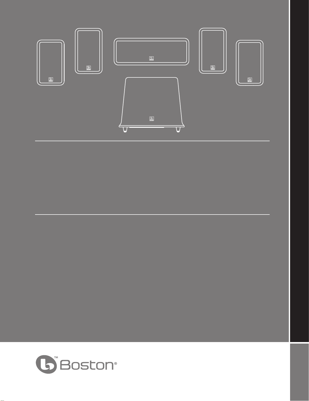
OWNER’S MANUAL / SAFETY INSTRUCTIONS / COMPLIANCE INFORMATION
HORIZON MCS 90
5.1 Surround Speaker System
Español
MCS 90
Sistema Multicanal Boston
Francais
MCS 90
Haut-parleur multivoix Boston
A Boston P.O.P. Product Make it your own...
Page 69
Important Safety Instructions
This symbol found on the apparatus
indicates hazards arising from dangerous voltages.
This symbol found on the apparatus
indicates the user should read all safety
statements found in the user manual.
This symbol found on the apparatus
indicates double insulation.
WARNING! To reduce the risk of re or electric
shock, do not expose this apparatus to rain or
moisture.
This symbol found on the apparatus indicates that the apparatus must be placed in a
separate collection facility for electronic
waste and not disposed of with household
waste.
1. Read these instructions.
2. Keep these instructions.
3. Heed all warnings.
4. Follow all instructions.
5. Do not use this apparatus near water.
6. Clean only with dry cloth.
7. Do not block any ventila
tion openings. Install in
accordance with the manufacturer's instructions.
8.
Do not install near any heat sources such as radiators, heat registers, stoves, or other apparatus
(including ampliers) that produce heat.
9.
Do not defeat the safety purpose of the polarized
or gr ounding-type plug. A polarized plug has
two blades with one wider than the other.
A grounding type plug has two blades and a
third grounding prong. The wide blade or the
third prong are provided for your safety. If the
provided plug does not t into your outlet,
consult an electrician for replacement of the
obsolete outlet.
10.
Protect the power cord from being walked on
or pinched particularly at plugs, convenience
receptacles, and the point where they exit
from the apparatus.
11. Only use attachments/accessories specied by
the manufactu
rer.
12. Unplug this apparatus during lightning storms
or when unused for long periods of time.
13.
Refer all servicing to qualied service personnel.
Servicing is required when the apparatus has
been damaged in any way, such as power sup-
spilled or objects have fallen into the apparatus, the apparatus has been exposed to rain or
moisture, does not operate normally, or has
been dropped.
14. Maintain a minimum distance of 50 mm around
the front, rear and sides of the apparatus for
sucient ventilation. The ventilation should not
be impeded by covering the ventilation openings or placing on or around the apparatus
items such as newspapers, table-cloths, curtains, etc.
15. No naked ame sources, such as ligh
ted
candles, should be placed on the apparatus.
16. The apparatus shall not be exposed to dripping or splashing. No objects lled with liq-
uids, such as vases, shall be placed on the
apparatus.
17. Either the power inlet connector on the rear of
the apparatus or the power plug at the wall
must remain accessible, to be able to disconnect power from the apparatus.
18. To completely disconnect this apparatus from
the AC Mains, disconnect the power supply
cord plug from the AC receptacle.
19. The mains plug of the power supply cord shall
remain readily operable.
2
Page 70

Specications Satellites Center Channel Subwoofer
Frequency Response: 120Hz – 20kHz 120Hz – 20kHz 40 - 180Hz
Recommended Amplier
Power Range: 10 – 100 watts 10 – 100 watts —
Sensitivity: 88dB [2.8v at 1m] 88dB [2.8v at 1m] —
Nominal Impedance: 8 ohms 8 ohms —
Crossover Frequency: 3,000Hz 3,000Hz —
Amplier Output: — — 100 watts RMS
Woofer: 3” with Phase Plugs 3” with Phase Plugs 8”
& MagnaGuard® & MagnaGuard
Tweeter:
Dimensions (H x W x D) 7
1
⁄2” (13mm)
3
⁄8 x 43⁄8 x 411⁄16” 511⁄16 x 125⁄8 x 33⁄4” 123⁄4 x 153⁄8 x 153⁄8”
1
⁄2” (13mm) —
(189 x 113 x 93mm) (145 x 321 x 95mm) (324 x 390 x 390mm)
Weight 2.5 lbs 4.6 lbs 22.7 lbs
(1.14kg) (2.1kg) (10.3kg)
MCS 90 Introduction
Thank you for purchasing a Boston Acoustics Multi-Channel Speaker System. These speakers incorporate high-quality
that produce the famous Boston sound. The system is ideally suited for use as a 5.1 channel solution in a high-quality home
theater or music system. The system is complete with everything you need for the typical speaker system including speaker
wire, satellite speakers, a center channel speaker, and a subwoofer. Please check out Bostonacoustics.com/placement for
information on placing your speakers.
The MCS 90 speaker system delivers exceptionally articulate on-screen dialog, music, eects, and room lling bass from a
small, sleek package. Compact driver placement and quality, system specic crossovers assure a wide uniform dispersion
for complete coverage of a listening room. All speakers also feature MagnaGuard® magnetic shielding which ensures the
speaker’s magnetic eld does not interfere with the televisions picture.
components
Unpacking the System
Carefully unpack the system. If there is any sign of damage from transit, report it immediately to your dealer and/or delivery
service. Keep the shipping carton and packing materials for future use. Open the package and verify the following contents:
(4) Satellite speakers
(1) Center Channel speaker
(1) Subwoofer
(2) 40’ (12m) speaker wires
(3) 15’ (4.6m) speaker wires
(1) 15’ (4.6m) subwoofer cable
(8) Rubber bumpers (used for wall mounting)
(4) Satellite speakers
with 1 removable foot
Subwoofer
(1) Center Channel speaker
with 2 removable feet
3
Page 71
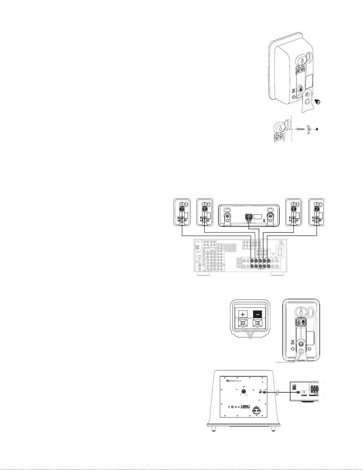
Placement Options
+ –
+ –
The MCS 90 satellites and center channel are easily placed on a tabletop or wall-mounted. The
speakers are congured for tabletop use when you rst unpack the system. The foot installed on
the rear of the speaker will keep it upright.
The MCS 90 satellites and center channel are designed to easily mount on the wall using the keyhole
slot(s) on the back of the speaker. When mounting the speakers to the wall use the supplied rubber
bumpers. You must remove the attached foot to wall-mount your speakers. Remove the thumbscrew
from the back of the foot. It is slotted for easy removal with a screwdriver or a coin.
The keyhole mounting option is similar to hanging a picture frame on a wall. Install a #8 screw (not
included) into the sheetrock, making sure to go into a stud, and hang the speaker onto the screw head.
If a stud is not available, a sheetrock anchor should be used to support the weight of the speaker. It is
advisable to connect the speaker wire prior to wall-mounting.
NOTE: Because there are so many dierent kinds of surfaces on which the speakers could be mounted. There is no one
type of fastener that we could supply that would work in all the possible situations. So taking into account the surface the
speaker is being mounted on, acquire the appropriate type of fasteners. If you’re not sure what type of fastener to use, take
the mounting bracket to a friendly hardware store, tell them about the wall you’re mounting the speaker on, and ask them
to recommend an appropriate fastener. Keep in mind the weight of the speaker.
Speaker Connections
After your speakers are properly placed, you are ready
to wire your system. First, turn o all system power.
Use the speaker wire included with the system to
make your connections. For longer distances, #16 or
#18 gauge wire available from your dealer should be
used. Please see the illustration for guidance connecting the wires to the MCS 90 satellites and center
channel.
For connection to your receiver please refer to its
owner’s manual.
Important!
To ensure the best performance observe polarities when making speaker
connections, as shown in the illustration. Connect each + terminal on the back of
the amplier or receiver to the respective + (red) terminal on each speaker. Connect
the – (black) terminals in the same way. If the connections are not made correctly it
can cause poor bass response and imaging. Also, to avoid short circuits that may
damage your equipment be careful not to let any of the bare wires touch each other.
Subwoofer Connections
Turn o all power. Use the subwoofer cable included with your
system to connect the subwoofer to your receivers Subwoofer or
LFE Output. Connect the other end to the “Line In” on the back of
the Subwoofer.
4
+ Red – Black
Page 72

Subwoofer Controls
MCS 90
Power On
Plug the subwoofer’s AC cord into a wall outlet. We do not recommend using use the
outlets on the back of the receiver. The subwoofer features auto on/standby. An LED
indicator next to the volume control indicates what mode the subwoofer is in.
RED = STANDBY (No signal detected, Amp O)
GREEN = ON (Signal detected, Amp On)
The subwoofer will automatically enter the Standby mode after several minutes when no signal is detected from your system.
The subwoofer will then power ON instantly when a signal is detected.
LED indicator
Volume Control
Begin by adjusting the Subwoofer Volume Control to the 11 o’clock position. Further adjust the Subwoofer Volume Control
until you hear a match in volume between the main speakers and subwoofer. Ideally, bass response should not overpower
the room but rather be adjusted so there is a natural blend across the entire musical range.
Operation
When using the MCS 90 in a Dolby® Digital or DTS™ home theater system, make sure all speakers are set to “Small”. When
using the system in a Dolby Pro Logic® home theater system, make sure the receiver’s center channel mode is set to “Normal.”
Some Dolby Digital equipped receivers/processors oer dierent setup options for each source or surround mode (e.g., CDstereo, videotape, Dolby Digital, Pro Logic®). In each case, follow your equipment’s instructions to ensure that the subwoofer
output is turned on and that the speakers are set to “Small” in each mode.
If your receiver has adjustable crossover settings, we recommend the subwoofer crossover be set at 150Hz.
Refer to the owner’s manual for your AV receiver for any additional recommendations on system operation.
Maintenance and Service
The satellite and subwoofer enclosures may be cleaned using a soft cloth to remove ngerprints or to wipe o dust. All wiring
connections should be inspected and cleaned or remade at least once a year.
If a problem does occur, make sure that all connections are properly made, secure and clean. If a problem occurs in one loudspeaker, rewire that speaker in a dierent location within the system. Should the problem persist in this speaker the problem
is within the speaker. If the speaker sounds ne in the new position it is a strong indication of a more in depth issue with the
electronics in the system. In the event that your MCS 90 ever needs service, contact your local Boston Acoustics dealer or visit
www.Bostona.com for a list of dealers in your area.
If your subwoofer does not play, check that all the connectors on the cables are making proper contact and that the AC plug
is connected to a “live” receptacle.
5
Page 73

Limited Warranty
Boston Acoustics warrants to the original purchaser of our MCS 90 system that it will be free of defects in materials and
workmanship in its mechanical parts for a period of 5 years from the date of purchase. The warranty period for the electrical
components of MCS 90 is 1 year.
Your responsibilities are to install and use them according to the instructions supplied, to provide safe and secure transportation to an authorized Boston Acoustics service representative, and to present proof of purchase in the form of your sales slip
when requesting service.
Excluded from this warranty is damage that results from abuse, misuse, improper installation, accidents, shipping, or repairs/
modications by anyone other than an authorized Boston Acoustics service representative.
This warranty is limited to the Boston Acoustics product and does not cover damage to any associated equipment. This
warranty does not cover the cost of removal or reinstallation. This warranty is void if the serial number has been removed or
defaced. This warranty gives you specic legal rights, and you may also have other rights which vary from state to state.
If Service Seems Necessary
First, contact the dealer from whom you purchased the product. If that is not possible, write to:
Boston Acoustics, Inc.
300 Jubilee Drive
Peabody, MA 01960 USA
Or contact us via e-mail at:
support@bostona.com
We will promptly advise you of what action to take. If it is necessary to return your MCS 90 to the factory, please ship it
prepaid. After it has been repaired, we will return it freight prepaid in the United States and Canada.
For EU Customers Only
This symbol found on the product indicates that the product must not be disposed of with household waste.
Instead, it may be placed in a separate collection facility for electronic waste or returned to a retailer when purchasing similar product. The producer paid to recycle this product. Doing this contributes to reuse and recycling,
minimizes adverse eects on the environment and human health and avoids any nes for incorrect disposal.
Boston Acoustics continually strives to update and improve its products. The specications and construction details are
subject to change without notice.
6
Page 74

20
300 Jubilee Drive, Peabody, MA 01960 USA
www.bostonacoustics.com
Boston, Boston Acoustics, MagnaGuard, Kortec, and the Boston Acoustics logo are registered trademarks of Boston Acoustics,
Inc. Dolby Digital, and Dolby Pro Logic are registered trademarks of Dolby Laboratories. DTS is a registered trademarks of DTS,
Inc. Specications are subject to change without notice. © 2008 Boston Acoustics, Inc. 142-003282-0
 Loading...