

Page 1
6
3
.
4
[
2
.49
6
]
ODE
ADD
R
E
S
Specifications
SHLD
CAN-
4
GND
SHL D
CAN -
5
3
2
1
IN 0
DR 0
DR 2
N
O
D
E
A
D
D
R
E
S
S
x16
0
1
6
3
.
4
[
2
.
4
9
6
]
ODE
ADD
RES
S
CANopen Connector
Type Removable connector (5.08mm)
Transmission
method
Transmission cable 2 communication cables, 1 shielded cable and 1 grounding cable
Electrical isolation 500V DC
Communication
Message type PDO, SDO, SYNC (synchronous object), Emergency (emergency object), NMT
Series transmission
speed
Product code 64
Equipment type 0 (Non-Profile)
Company ID 477 (Delta Electronics, Inc.)
Electrical Specifications
Power voltage 24V DC (-15% ~ 20%) (supplied by the internal bus from MPU)
Power consumption 1.7 W
Isolation voltage 500 V
Weight (approx. g) 66 (g)
Environment
Interference
immunity
Operation/Storage
Shock/vibration
immunity
Certificates IEC 61131-2, UL508
Configuration
CAN
10K, 20K, 50K,125K, 250K, 500K, 800K, 1M bps (bits per second)
ESD (IEC 61131-2, IEC 61000-4-2): 8KV Air Discharge, 4KV Contact
Discharge
EFT (IEC 61131-2, IEC 61000-4-4): Power Line: 2KV, Digital I/O: 1KV
Analog & Communication I/O: 1KV
Damped-Oscillatory Wave: Power Line: 1KV, Digital I/O: 1KV
RS (IEC 61131-2, IEC 61000-4-3): 80MHz ~ 1000MHz , 1.4GHz ~ 2.0GHz ,
10V/m
Operation: 0ºC ~ 55ºC (temperature), 50 ~ 95% (humidity), pollution degree 2
Storage: -25ºC ~ 70ºC (temperature), 5 ~ 95% (humidity)
International standards: IEC 61131-2, IEC 68-2-6 (TEST Fc)/IEC 61131-2 &
IEC 68-2-27 (TEST Ea)
DVPCOPM-SL modules are numbered automatically from 1 ~ 8 according to
their distance from the MPU (1 is the closest one). Maximum 8 modules are
extendable
Address Setup Rotary Switch
Address Setting Description
1 ~ 7F Valid CANopen node address
0, 80 ~ FF Invalid CANopen node address
LED Indicator & Trouble-shooting
RUN LED
LED Status Indication How to deal with it
Off No power
Green light single flash
Green light blinking
Green light steady on
ERROR LED
LED Status Indication How to deal with it
Off Normal No action needed
Red light single flash
Red light double flash Error control event See the indication from digital display.
Red light steady on Bus-off
Codes in Digital Display
Code Indication How to deal with it
0 ~ 7F
F1 No slaves configured in node list
F2
F3 DVPCOPM-SL in error status
F4 Bus-off is detected
F5 Incorrect DVPCOPM-SL settings
DVPCOPM-SL in STOP
status
DVPCOPM-SL in
pre-operational status
DVPCOPM-SL in operational
status
Bus error exceeds the
warning limit
The node address of DVPCOPM-SL when
in normal operation.
The data are being downloaded to
DVPCOPM-SL
Check the power of DVPCOPM-SL and
make sure the connection is normal.
No action needed
Check if the network connection and
operation are normal.
Check if the Bus connection is normal and
re-power DVPCOPM-SL
No action needed
Re-configured the node list and download it
to DVPCOPM-SL
No action needed
Check if the wiring of DVPCOPM-SL is
correct.
Make sure the communication cable is in
normal operation and all the nodes in the
network work in the same baud rate.
Re-power DVPCOPM-SL.
Check the settings of node address and
baud rate and make sure the settings are
correct.
通訊連接器
指示燈
繁體中文
390
390
個
個
注意事項
x16
使用前請務必仔細閱讀本使用手册,並按照本手册指示進行操作,以免造成産品受損或人員受傷。
配線時請務必關閉電源,當模組上電後,請勿觸摸接線端子。
此安裝手册只提供電氣規格、一般規格、安裝配線、故障排除及周邊裝置部分說明,本說明書僅作爲
DVPCOPM-SL
操作指南和入門參考,
CANopen
協定之內容,請參閱相關專業文章或書籍資料。
本機爲開放型(
Open Type
/
衝擊意外之外殼配線箱內。另必須具備保護措施(如:特殊之工具或鑰匙才可打開),防止非維護人員
操作或意外衝擊本體,造成危險及損壞。
交流輸入電源不可連接於輸入/輸出訊號端,否則可能造成嚴重損壞。請在上電前再次確認電源配線,
且請勿在上電時觸摸任何端子。本體上的接地端子
產品簡介
功能
1. 符合CANopen
標準協定
2. 支援NMT 服務
3. 支援Error Control Protocol
4. 支援SDO服務
5. 在CANopen
組態軟體中支援
産品外觀
5
6
1
DVPCOPM
POWER
RUN
3
ERR
1
x16
7
0
x16
N
DR 2
DR 1
DR 0
IN 0
90[3. 543]
8
SHLD
CAN-
9
GND
3 [0.11 8]
6
4
尺寸單位:
CANopen
)機殼,因此使用者使用本機時,必須將其安裝於具防塵、防潮及免於電擊
DS301v4.02
EDS
檔案配置
2
6
2
60 [2. 362]
mm 和 [inch]
協定之詳細內容這裏不作介紹。如讀者想瞭解更多
務必正確的接地,以提高産品抗雜訊能力。
6. 支援PDO
服務:
RxPDO
最大支援
200
個,資料量最大支援
最大支援
200
個,資料量最大支援
傳輸類型:支援事件觸發、時間觸發、同步週
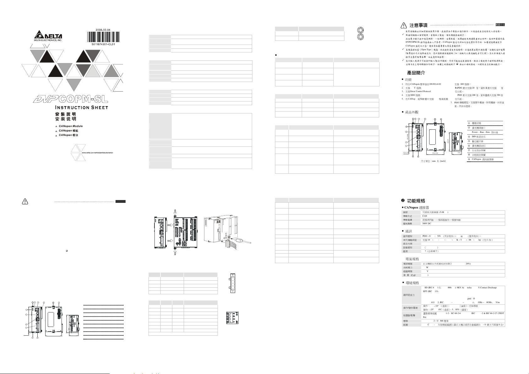
機種名稱
1
擴充機連接口
2
Power、Run、Error
3
DIN
軌固定扣
4
數位顯示器
5
擴充機固定扣
6
位址設定開關
7
功能設定開關
8
CANopen
9
7. PDO
期、同步非週期。
33.1 [1 .303 ]
位元組。
TxPDO
位元組。
Warning
Please read this instruction sheet carefully before use and follow the sheet to operate DVPCOPM-SL in order
to prevent damages on the device or injuries to staff.
Switch of the power when wiring. DO NOT touch any terminal when the power is switched on.
This instruction sheet only provides introductory information on electrical specifications, functions, wiring,
trouble-shooting and peripherals for DVPCOPM-SL. Details of CANopen protocol are not included in this
sheet. For more information on CANopen, please refer to relevant reference or literatures.
DVPCOPM-SL is an OPEN-TYPE device and therefore should be installed in an enclosure free of airborne
dust, humidity, electric shock and vibration. The enclosure should prevent non-maintenance staff from
operating the device (e.g. key or specific tools are required to open the enclosure) in case danger and
damages on the device may occur.
DO NOT connect input AC power supply to any of the I/O terminals; otherwise serious damage may occur.
Check all the wiring again before switching on the power and DO NOT touch any terminal when the power is
switched on. Make sure the ground terminal is correctly grounded in order to prevent electromagnetic
interference.
ENGLISH
Introduction
Functions
1. Complied with CANopen standard protocol
DS301v4.02
2. Supports NMT service
3. Supports Error Control Protocol
4. Supports SDO service
5. Supports EDS files in CANopen Configurator
Product Profile & Outline
5
6
1
2
DVPCOPM
POWER
RUN
3
ERR
1
S
x16
7
0
x16
N
DR 2
DR 1
DR 0
IN 0
90 [3. 543]
8
SHLD
CAN-
9
GND
3 [0 .118 ]
6
4
60 [2. 362 ]
Unit: mm and [inch]
6. Supports PDO service:
Supports max. 200 RxPDOs and the data can be
up to 390 bytes.
Supports max. 200 TxPDOs and the data can be
up to 390 bytes.
7. PDO transmission type: supports event trigger,
time trigger, synchronous cycle and synchronous
non-cycle.
6
2
33. 1 [ 1.3 03]
1
Model name
2
Connection port for extension unit
3
Power, Run, Error indicators
4
DIN rail clip
5
Digital display
6
Fixing clip for extension unit
7
Address setup rotary switch
8
Function setup DIP switch
9
CANopen connector
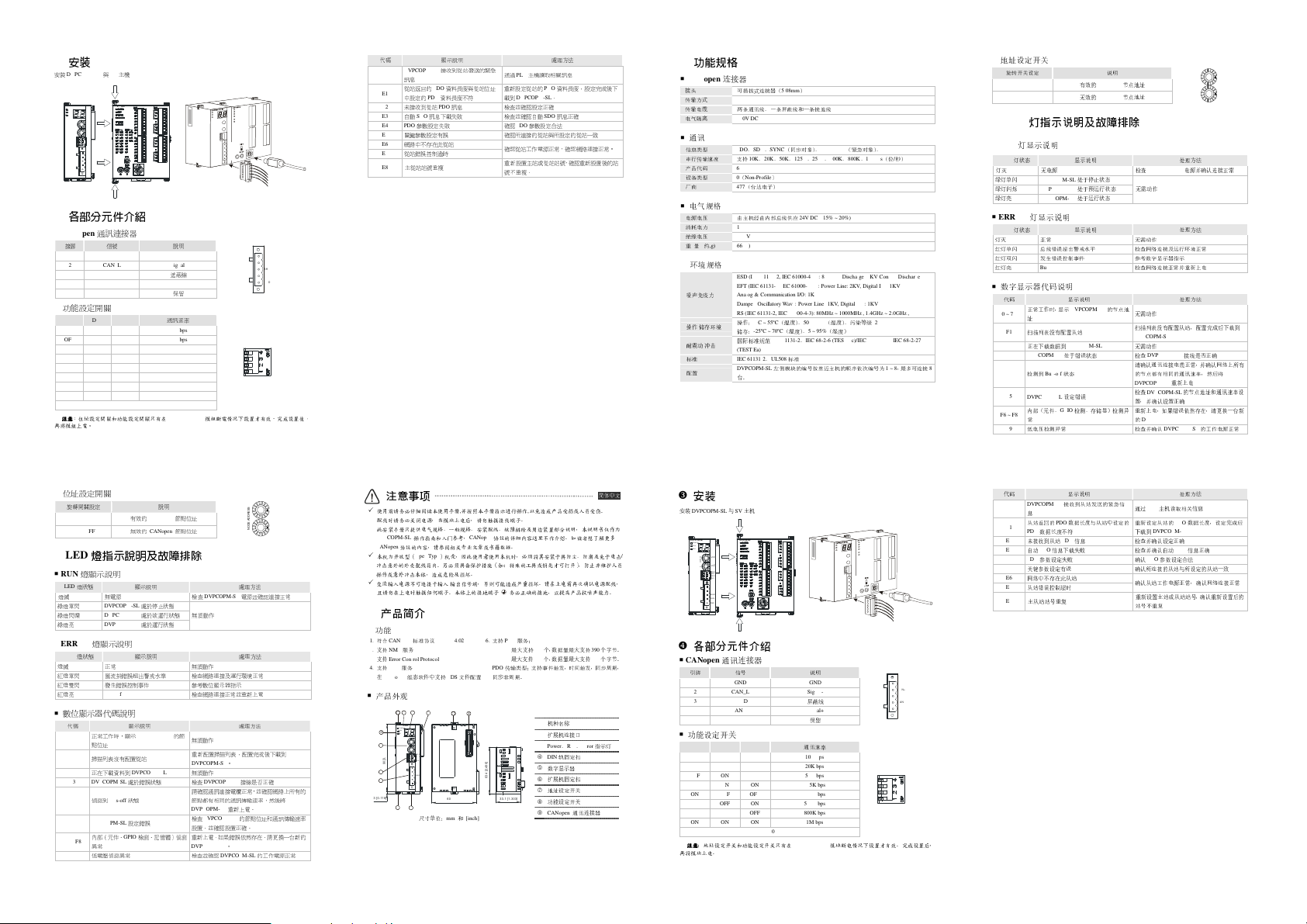
Installation
Connecting DVPCOPM-SL with SV series MPU
DVPCOPM
POWER
RUN
ERR
DVP28SV
1
x16
0
x16
NODEADDRES S
DR 2
DR 1
DR 0
IN 0
GND
Components
CANopen Connector
PIN Signal Description
1 GND GND
2 CAN_L Signal-
3 SHLD Shielded cable
4 CAN_H Signal+
5 - Reserved
Function Setup DIP Switch
DR2 DR1 DR0 Baud Rate
OFF OFF OFF 10K bps
OFF OFF ON 20K bps
OFF ON OFF 50K bps
OFF ON ON 125K bps
ON OFF OFF 250K bps
ON OFF ON 500K bps
ON ON OFF 800K bps
ON ON ON 1M bps
Note: The setup of address and function is only valid when the power of DVPCOPM-SL is switched off.
Re-power the module after the setup is completed.
IN 0
CAN +
DR 1
Code Indication How to deal with it
Internal (device, GPIO check, memory)
F6 ~ F8
abnormality is detected.
F9 Low voltage is detected.
DVPCOPM-SL receives Emergency
E0
message sent by the Slave.
PDO data length returning from the Slave is
E1
not consistent with the length set in the
Slave address
PDO message from the Slave has not been
E2
received.
E3 Auto SDO download failed. Check and make sure Auto SDO is correct.
E4 PDO parameter setting has failed.
E5 Error in key parameter setting
E6 The Slave does not exist in the network.
Slave’s Error control is time-out
E7
E8 Master/slave node address is repeated
Re-power DVPCOPM-SL. If the error still
exists, change to a new DVPCOPM-SL
Check and make sure the power of
DVPCOPM-SL works normally.
Read relevant information through PLC
MPU.
Reset the PDO data length in the Slave and
download the new setting to DVPCOPM-SL
Check and make sure the setting is correct.
Make sure the PDO parameter setting is
legal.
Make sure all the Slaves connected are
consistent with the Slaves set.
Make sure the power of the Slave and the
network connection work normally.
Reset the node address and make sure the
new node address is not repeated one.
功能規格
CANopen
連接器
接頭
傳輸方式
傳輸電纜
電氣隔離
通訊
資訊類型
串列傳輸速度 支援
産品代碼
設備類型
廠商
ID 477
電氣規格
電源電壓 由主機經由內部匯流排供應
消耗電力
絕緣電壓
重 量
(約,g)
環境規格
雜訊免疫力
操作/儲存環境
耐震動/衝擊
標準
IEC 61131-2、UL508標準
配置
DVPCOPM-SL
可插拔式連接器
CAN
500V DC
PDO、SDO、SYNC
0(Non-Profile)
(5.08mm)
兩條通訊線、一條遮蔽線和一條接地線
10K、20K、50K、125K、250K、500K、800K、1M bps
64
(台達電子)
1.7 W
500 V
66 (g)
ESD (IEC 61131-2, IEC 61000-4-2): 8KV Air Discharge, 4KV Contact Discharge
EFT (IEC 61131-2, IEC 61000-4-4): Power Line: 2KV, Digital I/O: 1KV
Analog & Communication I/O: 1KV
Damped-Oscillatory Wave: Power Line: 1KV, Digital I/O: 1KV
RS (IEC 61131-2, IEC 61000-4-3): 80MHz ~ 1000MHz , 1.4GHz ~ 2.0GHz , 10V/m
操作:
0ºC ~ 55ºC
(溫度)、
儲存:
-25ºC ~ 70ºC
國際標準規範
IEC 61131-2、IEC 68-2-6 (TEST Fc)/IEC 61131-2 & IEC 68-2-27 (TEST
Ea)
左側模組編號以靠近主機之順序自動編號由
(同步物件)、
24VDC (-15% ~ 20%)
50 ~ 95%
(溫度)、
Emergency
(濕度)、污染等級
5 ~ 95%
(濕度)
(緊急物件)、
2
1 ~ 8
NMT
(位元/秒)
,最大可連接8台。
Page 2
安裝
SHLD
CAN-
4
GND
SHLD
CAN-
5
2
DR 0
DR 2
N
O
D
E
A
D
D
R
E
S
S
0
1
6
3.4
[
2
.
4
9
6
]
ODE
ADD
RES
S
SHLD
CAN-
2
IN 0
DR 0
N
O
D
E
A
D
D
R
E
S
S
0
1
安裝
DVPCOPM-SL與SV主機
DVPCOPM
POWER
RUN
ERR
各部分元件介紹
CANopen
接腳 信號
功能設定開關
DR2 DR1 DR0
OFF OFF OFF 10K bps
OFF OFF ON 20K bps
OFF ON O FF 50K bps
OFF ON O N 125K bps
ON OFF OFF 250K bps
ON OFF O N 500K bps
ON ON OFF 800K bps
ON ON ON 1M bps
注意
注意
注意注意
再將模組上電。
位址設定開關
旋轉開關設定
LED
RUN
LED
燈滅
綠燈單閃
綠燈閃爍
綠燈亮
ERROR
LED
燈滅
紅燈單閃 匯流排錯誤超出警戒水準 檢查網路連接及運行環境正常
紅燈雙閃 發生錯誤控制事件
紅燈亮
數位顯示器代碼說明
代碼
0 ~ 7F
F6 ~ F8
DVP28SV
1
x16
0
x16
NODEADDRE SS
DR 2
DR 1
DR 0
IN 0
GND
通訊連接器
1 GND GND
2 CAN_L Signal-
3 SHLD
4 CAN_H Signal+
5 -
說明
遮蔽線
保留
通訊速率
IN 0
:位址設定開關和功能設定開關只有在
1 ~ 7F
0, 80 ~ FF
有效的
無效的
說明
CANopen
CANopen
DVPCOPM-SL
節點位址
節點位址
燈指示說明及故障排除
燈顯示說明
燈狀態
顯示說明
無電源 檢查
DVPCOPM-SL
DVPCOPM-SL
DVPCOPM-SL
燈顯示說明
燈狀態
正常
Bus-off
正常工作時,顯示
點位址
掃描列表沒有配置從站
F1
正在下載資料到
F2
DVPCOPM-SL
F3
偵測到
Bus-off狀態
F4
DVPCOPM-SL
F5
內部(元件、
異
常
低
電壓偵測異常
F9
處於停止狀態
處於欲運行狀態
處於運行狀態
顯示說明
顯示說明
DVPCOPM-SL
DVPCOPM-SL
處於錯誤狀態 檢查
設定錯誤
GPIO
檢測、記憶體)偵測
的節
模組斷電情况下設置才有效。完成設置後,
處理方法
DVPCOPM-SL
電源並確認連接正常
無須動作
無須動作
參考數位顯示器指示
檢查網路連接正常並重新上電
處理方法
處理方法
無須動作
重新配置掃描列表,配置完成後下載到
DVPCOPM-SL。
無須動作
DVPCOPM-SL
DVPCOPM-SL
DVPCOPM-SL
接線是否正確
重新上電。
的節點位址和通訊傳輸速率
請確認通訊連接電纜正常,並確認網路上所有的
節點都有相同的通訊傳輸速率,然後將
DVPCOPM-SL
檢查
設置,並確認設置正確。
重新上電,如果錯誤依然存在,請更換一台新的
DVPCOPM-SL。
檢查並確認
CAN+
DR 1
IN 0
x16
x16
的工作電源正常
代碼
E0
E1
E2
E3
E4
E5
E6
E7
E8
3
1
注意事項
使用前请务必仔细阅读本使用手册,并按照本手册指示进行操作,以免造成产品受损或人员受伤
配线时请务必关闭电源,当模块上电后,请勿触摸接线端子
此安装手册只提供电气规格、一般规格、安装配线、故障排除及周边装置部分说明,本说明书仅作为
DVPCOPM-SL
CANopen
本机为开放型(
冲击意外的外壳配线箱内。另必须具备保护措施(如:特殊的工具或钥匙才可打开),防止非维护人员
操作或意外冲击本体,造成危险及损坏
交流输入电源不可连接于输入/输出信号端,否则可能造成严重损坏。请在上电前再次确认电源配线
且请勿在上电时触摸任何端子。本体上的接地端子
產品簡介
功能
1. 符合CANopen
2. 支持NMT服务
3. 支持Error Control Protocol
4. 支持SDO服务
5. 在CANopen
产品外观
3
7
90 [3.543]
8
9
3 [0. 118]
顯示說明
到從站
SDO
參數設定
PDO
PDO
訊息下載
接收到從站發送的緊急
資料長度與從站位址
資料長度不符
PDO
訊
息
失敗
失敗
複
通
過
PLC
重新設定從站的
載到
DVPCOPM-SL。
檢查並確認設定正確
檢查並確認自動
確認
PDO
確認所連接的從站與所設定的從站一
確認從站工作電源正常,確認網路連接正常。
重新設置主站或從站站號,確認重新設置後的站
號不重複。
DVPCOPM-SL
訊
息
從站返回的
中設定的
未接收
自動
PDO
關鍵參數設定有誤
網路中不存在此從站
從站錯誤控制逾時
主從站站號重
。
操作指南和入门参考
协议的内容,请参阅相关专业文章或书籍数据
Open Type
,
CANopen
协议的详细内容这里不作介绍。如读者想了解更多
。
)机壳,因此使用者使用本机时,必须将其安装于具防尘、防潮及免于电击
。
务必正确的接地,以提高产品抗噪声能力
标准协议
组态软件中支持
5
6
1
DVPCO PM
POWER
RUN
ERR
N
6
4
1
x16
0
x16
DR 2
DR 1
DR 0
IN 0
SHLD
CAN-
GND
尺寸单位:
DS301v4.02
2
EDS
文件配置
6
2
60 [2 .36 2]
mm 和 [inch]
6. 支持PDO
服务:
RxPDO
最大支持
TxPDO
最大支持
7. PDO
传输类型:支持事件触发,时间触发,同步周期,
同步非周期。
33.1 [ 1.3 03]
主機讀取相關訊
PDO
SDO
參數設定合法
200
个,数据量最大支持
200
个,数据量最大支持
1
机种名称
2
扩展机连接口
3
Power、Run、Error
4
DIN
5
数字显示器
6
扩展机固定扣
7
地址设定开关
8
功能设定开关
9
CANopen
處理方法
息
資料長度,設定完成後下
訊息正確
致
390
390
轨固定扣
通讯连接器
简体中文
。
个字节。
个字节。
指示灯
地址设定开关
功能規格
CANopen
连接器
接头
传输方式
传输电缆
电气隔离
通讯
信息类型
串行传输速度 支持
产品代码
设备类型
厂商
ID 477
电气规格
电源电压 由主机经由内部总线供应
消耗电力
绝缘电压
重 量
(约,g)
环境规格
噪声免疫力
操作/储存环境
耐震动/冲击
标准
IEC 61131-2、UL508标准
配置
可插拔式连接器(
PDO、SDO、SYNC
64
0(Non-Profile)
5.08mm)
CAN
两条通讯线、一条屏蔽线和一条接地线
500V DC
10K、20K、50K、125K、250K、500K、800K、1M bps(位/秒)
(台达电子)
1.7 W
500 V
66 (g)
ESD (IEC 61131-2, IEC 61000-4-2) : 8KV Air Discharge, 4KV Contact Discharge
EFT (IEC 61131-2, IEC 61000-4-4) : Power Line: 2KV, Digital I/O: 1KV
Analog & Communication I/O: 1KV
Damped-Oscillatory Wave: Power Line: 1KV, Digital I/O: 1KV
RS (IEC 61131-2, IEC 61000-4-3): 80MHz ~ 1000MHz , 1.4GHz ~ 2.0GHz , 10V/m
操作:
0ºC ~ 55ºC
(温度)、
储存:
-25ºC ~ 70ºC
(温度)、
国际标准规范
IEC 61131-2、IEC 68-2-6 (TEST Fc)/IEC 61131-2 & IEC 68-2-27
(TEST Ea)
DVPCOPM-SL
左侧模块的编号按靠近主机的顺序依次编号为
台。
(同步对象)、
24V DC (-15% ~ 20%)
50 ~ 95%
5 ~ 95%
Emergency
(紧急对象)、
(湿度)、污染等级
(湿度)
NMT
2
1 ~ 8
,最多可连接
8
LED
RUN
LED
灯灭
绿灯单闪
绿灯闪烁
绿灯亮
ERROR
LED
灯灭
红灯单闪 总线错误超出警戒水平
红灯双闪 发生错误控制事件
红灯亮
数字显示器代码说明
0 ~ 7F
F6 ~ F8
/
,
。
安裝
安装
DVPCOPM-SL与SV主机
DVPCOPM
CANopen
引脚
功能设定开关
DR2 DR1 DR0
OFF O FF OFF 10K bps
OFF O FF ON 20K bps
OFF ON OFF 50K bps
OFF ON ON 125K bps
ON OFF OFF 250K bps
ON OFF ON 500K bps
ON ON OFF 800K bps
ON ON ON 1M bps
注意
注意:地址设定开关和功能设定开关只有在
注意注意
再将模块上电
DVP28SV
POWER
RUN
ERR
1
x16
0
x16
NODEADDRE SS
DR 2
DR 1
DR 0
IN 0
GND
各部分元件介紹
通讯连接器
1 GND GND
2 CAN_L Signal-
3 S HLD
4 CAN_H Signal+
5 -
信号
IN 0
。
说明
屏蔽线
保留
通讯速率
DVPCOPM-SL
模块断电情况下设置才有效。完成设置后
5
CAN+
4
SHLD
3
CAN-
GND
1
DR 2
DR 1
,
旋转开关设定
1 ~ 7F
0, 80 ~ FF
燈指示說明及故障排除
灯显示说明
灯状态
无电源
灯显示说明
正常
测到
Bus-off状态
电压检测异常
数据长度不符
从站
动
SDO
信息下载
参数设定
主从站站号重
显示说明
处于停止状态
处于预运行状态
处于运行状态
显示说明
显示说明
DVPCOPM-SL
到
DVPCOPM-SL
处于错误状态
设定错误
GPIO
检测、存储器)检
显示说明
接收到从站发送的紧急信
PDO
数据长度与从站中设定的
PDO信息
失败
失败
复
DVPCOPM-SL
DVPCOPM-SL
DVPCOPM-SL
灯状态
Bus-off
代码
正常工作时,显示
址
F1
扫描列表没有配置从站
F2
正在下载数据
F3 DVPCOPM-SL
F4
检
F5
DVPCOPM-SL
内部(元件、
常
F9
低
代码
DVPCOPM-SL
E0
息
从站返回的
E1
PDO
E2
未接收到
E3
自
E4 PDO
E5
关键参数设定有误
E6
网络中不存在此从站
E7
从站错误控制超时
E8
有效的
无效的
说明
CANopen
节点地址
CANopen
节点地址
检查
无需动作
无需动作
检查网络连接及运行环境正常
参考数字显示器指示
检查网络连接正常并重新上电
的节点地
无需动作
扫描列表没有配置从站,配置完成后下载
DVPCOPM-SL
无需动作
检查
请
确认通讯连接电缆正常,并确认网络上所有
的节点都有相同的通讯速率,然后
DVPCOPM-SL
检查
置,并确认设置正确
测异
重新上电,如果错误依然存在,
的
检查并确认
通
过
重新设定从站的
下载
检查并确认设定正确
检查并确认自动
确认
确认所连接的从站与所设定的从站一
确认从站工作电源正常,确认网络连接正常
重新设置主站或从站站号,确认重新设置后的
站号不重
DVPCOPM-SL
DVPCOPM-SL
DVPCOPM-SL
DVPCOPM-SL
DVPCOPM-SL
PLC
主机
到
DVPCOPM-SL
PDO
参数设定合法
复
处理方法
电源并确认连接正常
处理方法
处理方法
接线是否正确
重新上电
的节点地址和通讯速率设
的工作电源正常
处理方法
读取相
关信息
PDO
数据长度,设定完成后
SDO
信息正确
请更换
x16
x16
到
将
一台新
致
 Loading...