

Page 1

Delta Dual V4/V6 (DMS-217/079)
Installation Instructions
For Ground Water Applications
01992 523523
T.
info@deltamembranes.com
E.
www.deltamembranes.com
W.
Page 2

Delta Dual V4/V6
Legal information/Copyright
All rights reserved. Contents provided herein must neither be distributed, copied, reproduced, edited or
processed for any other purpose, nor otherwise transmitted, published or made available to a third party
without express written consent from Delta Membranes.
Subject to technical modication without prior notice.
© Delta Membranes 2015
DDV4V6-M-V1-12.15
Page 3

Delta Dual V4/V6
Contents
1.0 Dual V4/V6 Overview 4
2.0 Parts Included 4
2.1 Optional Extras 4
3.0 Discharge Pipework & Fittings 5
4.0 Chamber Overview 6
5.0 Spare Parts 6
6.0 Technical Information 7
7.0 Pump Chamber Depth Limits 8
8.0 Installation Guidelines 9
9.0 Pump Station Location 9
10.0 RC Box Dimensions 9
11.0 Installation of Chamber 10
Section A - Construction of reinforced concrete box 10
Section B1 - Connecting 110mm pipework 11
Section B2 - Connecting perimeter channel to chamber 12
Section B3 - Connecting perimeter channel via a 1.5"/40mm inlet pipe 13
Section C - Connecting discharge and cable duct 14
Section D1 - Backll around chamber with concrete (RC Box) 16
Section D2 - Backll around chamber with concrete (Ground) 17
Section D3 - Backll around chamber with concrete (Reinforced cage) 18
Section E - Installing pumps and high level alarm in chamber 19
12.0 Wiring Diagram 22
13.0 Maintenance 23
14.0 Health and Safety 23
15.0 Guarantee 23
16.0 Troubleshooting 24
17.0 Self Commissioning 25
18.0 Notes 27
For technical support, please call 01279 757400 3
Page 4

Delta Dual V4/V6
1.0 Dual V4/V6 Overview
The Delta Dual V4/V6 is a packaged pump station designed to collect ground water via perimeter channel or Delta
129 detail and/or clear opening to the top of the chamber - please visit our website for water collection details.
Typically, the Dual V4/V6 would be used to collect ground water from a basement up to 150m² and/or surface water
from a light well up to 12m² to a maximum head of 7m and 9m respectively.
The pump station has been specically designed for below ground applications. The chamber is manufactured from
HDPE and when installed correctly, it is able to withstand hydrostatic forces encountered in high water tables.
The pump station is delivered as a complete package including, the chamber, internal pipework and two powerful
V4/V6 pumps. It is designed to be installed by contractors with competent building, plumbing and electrical skills.
The pumps operate by xed arm oats, the duty pump is set at a standard height (210mm to base of oat) and the
backup pump is set at a high level (380mm to base of oat). The high level alarm (where tted) will operate if the duty
pump fails leaving the backup pump to discharge water.
A high level alarm (DMS-270) is oered as a recommended extra to alert the property occupant when the water level
in the chamber becomes too high. A battery backup (DMS-320) is recommended to power the pumps during power
outage. Please see section 2.1 for more details about optional extras designed for the Dual V4/V6 pump station.
2.0 Parts Included
Chamber - 660 diameter
(902 across spigots) x
800mm deep
2.1 Optional Extras
1.25” Internal Pipework
2 x V4/V6 Pumps 2” Discharge Male Iron
for temp. site installation.
2" Cable Duct Male Iron
AlertMaxx High Level
Alarm (DMS-270)
4 For technical support, please call 01279 757400
Power Plus Battery
Backup (DMS-320)
2" Discharge Pipework
and various ttings
Page 5

Delta Dual V4/V6
3.0 Discharge Pipework & Fittings
A selection of discharge pipework and ttings are available for the Dual V4/V6 pump station.
Should you require to place an order for any of these items, please complete the form below, scan and email to
purchasing@deltamembranes.com to allow us to process your order.
Part Description Part No. Qty Req.
2" Pipe - 3m Length (Class E) DMS-0154
2" 90° Elbow - Plain/Plain DMS-0155
2" 45° Elbow - Plain/Plain DMS-0156
2" Socket - Plain/Plain DMS-0157
2" Socket - BSP Mail Thread/BSP Male Thread DMS-0339
2" Male Iron - Plain/BSP Male Thread DMS-0153
2" Male Iron - Plain/BSP Male Thread (Non-pressure) DMS-335
110mm to 2" Adaptor DMS-341
Saddle Clamp - 110mm to 2" (BSP Female Thread) including 1.25" Male Iron DMS-0151
Saddle Clamp - 160mm to 2" (BSP Female Thread) including 1.25" Male Iron DMS-0152
2" Pipe Clip DMS-059
500ml PVC Solvent Cement DMS-0158
Name:
Company Name:
Property Address:
Email:
Phone No.: Mobile No.:
Sign: Date:
5
Please scan this order form and email to the purchasing@deltamembranes.com
Page 6
Delta Dual V4/V6
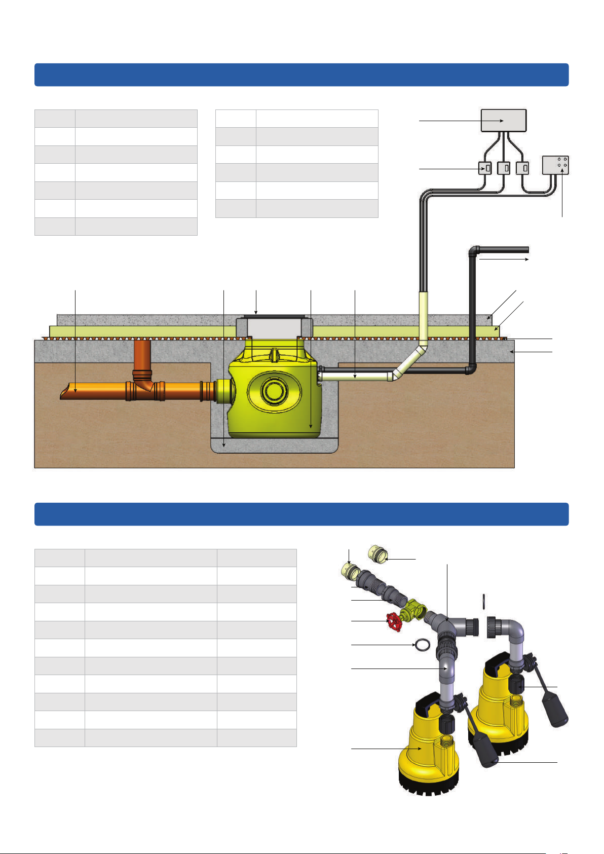
4.0 Chamber Overview
Part Description
A
B
C
D
E
F
A C E
Inlet Pipe
Concrete Base
Inspection Cover
Pump Chamber
Cable Duct
Fused Spur
G
H
I
J
K
L
B D
Distribution Board
High Level Alarm Box
Screed
Insulation
MS20
Basement Slab
G
F
H
TO SEWER
I
J
K
L
5.0 Spare Parts
Part Description Part No.
1
1.1
1.2
2
3
4
5
6
7
8
V4/V6 Pump c/w 1.1 & 1.2 DMS-216/084
Float & Switch Assembly DMS-344
Non-return Valve DMS-328
Discharge Arm DMS-326
‘O’ Ring DMS-132
1.25” Brass Gate Valve DMS-329
Connector Piece DMS-338
Connector Adaptor DMS-337
2” Non-pressure Male Iron DMS-335
Y-piece c/w 2 ’O’ rings DMS-321
7
6
5
4
3
2
1
7
8
1.2
1.1
6 For technical support, please call 01279 757400
Page 7

Delta Dual V4/V6
6.0 Technical Information
Pump Specication
Pump Type V4 V6
Typical Duty (I/s) Head (m)
Power P
Current (a)
Power Phase
Fuse Spur Rating (a)
Max. Temperature (°C)
Weight (kg)
Chamber Specication
Chamber Material
High Density Polyethnylene - ICO1314 grade
3
3.5
4
4.5
5
6
(kW)
1
P2 (kW)
3.25 3.75
3.10 3.60
3.00 3.50
2.90 3.40
2.75 3.30
2.40 3.00
0.75 1.05
0.35 0.50
4.00 4.90
Single Single
13 13
50 50
7.17 7.40
Size (mm) Chamber Diameter
Overall Diameter
Depth
Volume (L) Below Inlet
Total
Inspection Cover
Clear opening to chamber (mm)
Fixed Inlets
Cable Duct (mm)
Vent
Discharge Connection
Internal Pipework Manifold
RCBO Rating (a)
Cable Length (m)
Non-switched Fuse Spur Rating (a)
2" / 50mm BSP Female - External to chamber
660
902 (across spigots)
800
137
273
Not supplied
310 x 310
3 x 110 / 160mm
50
N/A
1.25" / 32mm BSP Class C
16
10
13
For technical support, please call 01279 757400 7
Page 8
Delta Dual V4/V6
7.0 Pump Chamber Depth Limits
If the inlet does not allow the pump chamber to be within depth limits, please contact PPS on 01279 757400 to
discuss chamber options.
< 500mm
The pump chamber must be installed no more than
500mm below oor nishes.
> 500mm
A pump chamber installed more than 500mm below
oor nishes cannot be serviced safely in accordance
with CDM regulations.
8 For technical support, please call 01279 757400
Page 9
Delta Dual V4/V6
8.0 Installation Guidelines
The following instructions are for guidance only and it is the contractor's responsibility to ensure that the
installation is in accordance with the prevailing ground conditions and good building practice, to eliminate any
potential damage to the pump station either during or after installation.
Please read these instructions carefully prior to installing the chamber. If there is anything that is unclear, our technical
help desk is available on 01279 757400.
9.0 Pump Station Location
This station requires routine maintenance, therefore it is important that careful consideration is taken to position the
chamber in a location that allows permanent access to the chamber.
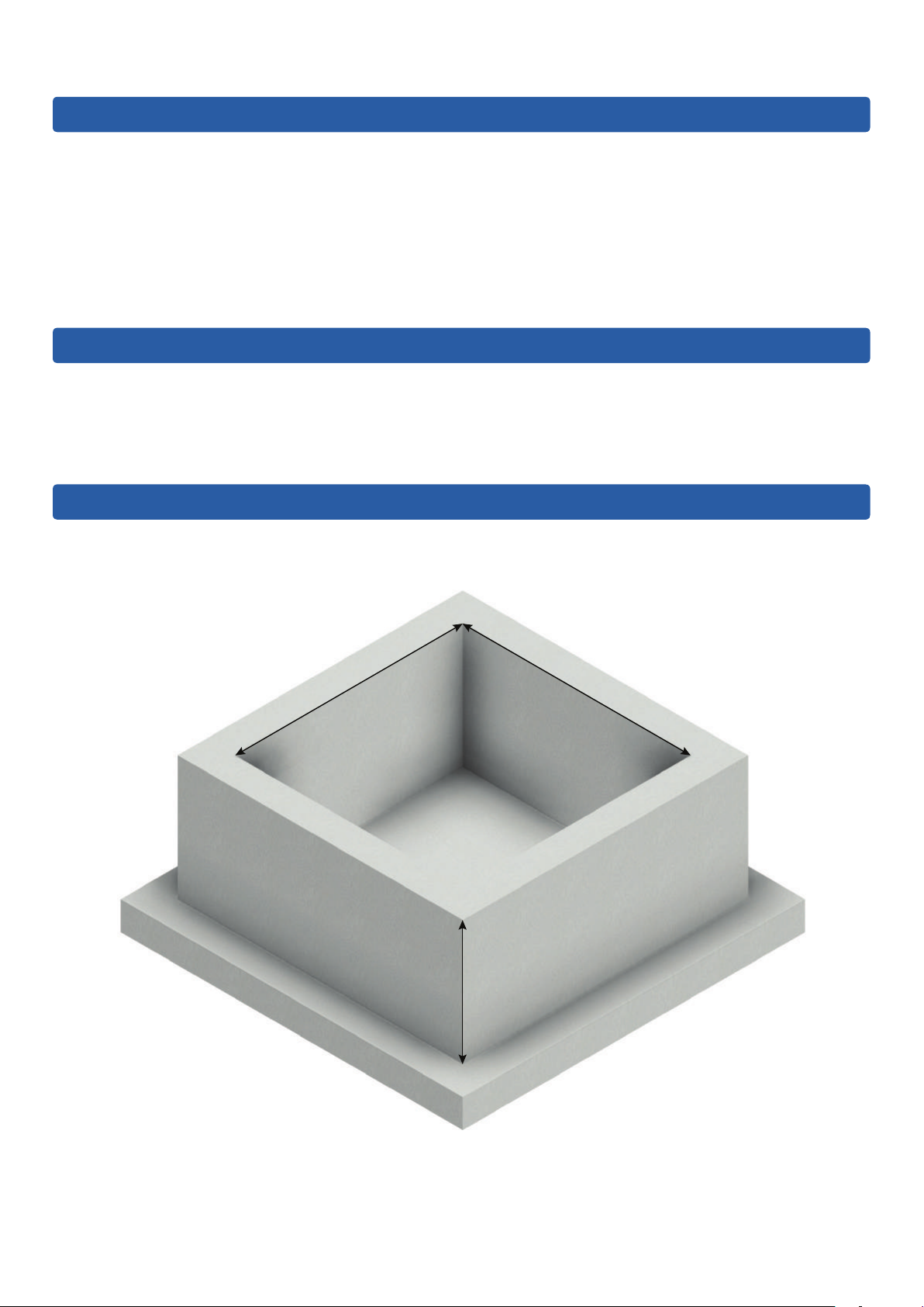
10.0 RC Box Dimensions
1200mm
1200mm
800mm
For technical support, please call 01279 757400 9
Page 10

Delta Dual V4/V6
11.0 Installation of Chamber - Section A
Construction of reinforced concrete box
1
Excavate hole for chamber. Refer to section 10.0 for
RC box internal dimensions.
2
Install re-bar as per structural engineer's drawings.
3
Lay inlet and discharge pipework. Allow pipework to
protrude into RC box by a minimum of 100mm.
4
Pour concrete to form RC box as per structural
engineer's drawings.
10 For technical support, please call 01279 757400
Page 11

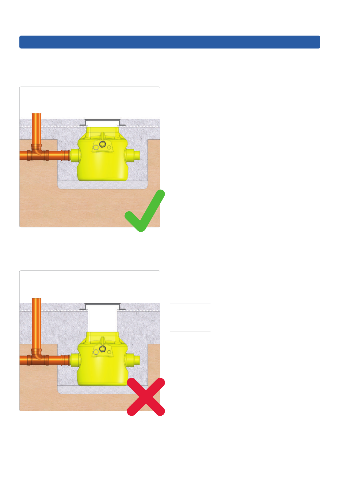
11.0 Installation of Chamber - Section B1
Connecting 110mm pipework
Delta Dual V4/V6
5
Saw o socket end/s, where inlet pipe/s are to
be connected.
6
Position chamber in RC box.
7
Fit push t coupler.
8
Connect inlet pipework to the required chamber spigot.
For technical support, please call 01279 757400 11
Page 12

Delta Dual V4/V6
11.0 Installation of Chamber - Section B2
Connecting perimeter channel to chamber
To be followed when installing perimeter channel directly into upper side of chamber.
9
Mark perimeter channel position on side of chamber.
10
Drill holes in the corners inside the area marked in red.
11
Cut around the marked line outlining the perimeter
channel using a jigsaw.
12
Insert the perimeter channel into the chamber allowing
35mm of overhang inside the chamber.
12 For technical support, please call 01279 757400
Page 13

11.0 Installation of Chamber - Section B3
Connecting perimeter channel via a 1.5"/40mm inlet pipe
Delta Dual V4/V6
13
Mark position of the 40mm pipe on the side of
the chamber and cut out the marked line using a
1.5"/40mm holesaw.
14
Cut 40mm pipe to length allowing an overhang of
35mm inside the chamber.
15
Saw o 110mm socket end/s to be used.
16
Attach a DMS-341 adaptor to the 40mm pipe and
connect the adaptor to the chamber via a 110mm
push t coupler.
For technical support, please call 01279 757400 13
Page 14

Delta Dual V4/V6
11.0 Installation of Chamber - Section C
Connecting discharge and cable duct
17
Wrap the thread on a DMS-0153 high pressure
male iron with PTFE tape.
18
Screw the high pressure male iron into the female iron.
19
Apply DMS-0158 high pressure glue around the rst
20mm of the external face of the discharge and cable
duct pipe and internal side of their respective male iron.
20
Push discharge and cable duct pipe into their
respective male iron, twisting the pipe as it is pushed
into the male iron to remove any trapped air.
14 For technical support, please call 01279 757400
Page 15

11.0 Installation of Chamber - Section C cont.
Connecting discharge and cable duct
21
Delta Dual V4/V6
Ensure a draw cord is pulled through the cable duct as
the cable duct is built.
For technical support, please call 01279 757400 15
Page 16

Delta Dual V4/V6
11.0 Installation of Chamber - Section D1
Backll around chamber with concrete
To be followed when installing chamber in an RC box.
22
Check all pipes are connected to the chamber
correctly.
23
Completely ll chamber with water.
24
Fill void between RC box and chamber with concrete
(min. C35 grade) or as per engineer's drawings.
16 For technical support, please call 01279 757400
Page 17

11.0 Installation of Chamber - Section D2
Backll around chamber with concrete
To be followed when installing chamber in the ground.
Delta Dual V4/V6
25
Completely ll chamber with water.
26
Fill void between soil and chamber with concrete
(min. C35 grade) or as per engineer's drawings.
27
Allow concrete to cure.
For technical support, please call 01279 757400 17
Page 18

Delta Dual V4/V6
11.0 Installation of Chamber - Section D3
Backll around chamber with concrete
To be followed when installing chamber in the ground with a reinforced cage.
28
Completely ll chamber with water.
29
Fill void between soil and chamber with concrete
(min. C35 grade) or as per engineer's drawings.
30
Allow concrete to cure.
18 For technical support, please call 01279 757400
Page 19

11.0 Installation of Chamber - Section E
Installing pumps and high level alarm in chamber
Delta Dual V4/V6
31
Pump out water from chamber.
32
Manually remove any debris from chamber and
residual water using a wet vac.
33
Remove discharge arms from 'Y' piece manifold and
screw 'Y' piece on to gatevalve. Ensure gatevalve is
fully open.
34
Wrap PTFE tape around thread located on male irons
at the bottom of the discharge arms and screw
discharge arms on to pumps.
For technical support, please call 01279 757400 19
Page 20

Delta Dual V4/V6
11.0 Installation of Chamber - Section E cont.
Installing pumps and high level alarm in chamber
35
Fill chamber half full with water.
36
Lower pumps in to chamber. Ensure 'O' rings are
correctly seated in unions and screw discharge arms to
'Y' piece manifold.
37
When installing a high level alarm, refer to the high
level alarm installation instructions.
38
Pull pump and high level alarm cables through cable
duct.
20 For technical support, please call 01279 757400
Page 21

11.0 Installation of Chamber - Section E cont.
Installing pumps and high level alarm in chamber
Delta Dual V4/V6
39
Isolate main supply and connect each pump and
high level alarm cable to a separate non-switched
fused spur.
40
Turn mains supply on and lift each pumps oat arm to
test water is discharging correctly.
41
To test oat switch, refer to the high level alarm
installation instructions.
42
Re-t temporary site cover to protect the pump station.
For technical support, please call 01279 757400 21
Page 22

Delta Dual V4/V6
Issue: 14/10/14.1.PPS/DPWD
12.0 Wiring Diagram
Available as part of a
and separatly.
level alarm, please see the
packaged pump chamber
High Level Alarm (DMS-270)
high level alarm instruction
manual.
For internal wiring of the high
13 Amp Non-switched fused spur
Separate 16 Amp RCBO's
fused spur
13 Amp Non-switched
L NE L NE L NE
with a 10m cable length.
- The pump and float switch is supplied
- When only using the standard 10m
Cable Length
than 6m, please follow the cable
- If the cable duct needs to be longer
appropriate cable core diameter.
cable attached to pump, the cable duct
extension guide to select an
length should be no longer than 6m.
(where fitted)
Battery Backup
22 For technical support, please call 01279 757400
Page 23

Delta Dual V4/V6
13.0 Maintenance
British Standards requires pump chambers to be serviced on a regular basis to ensure reliable operation of
equipment. PPS recommends that the pump station is serviced biannually.
PPS strongly recommends that a service agreement is taken out, please see the back page for further information.
14.0 Health and Safety
In order to minimise the risk of accidents when installing and servicing pump chambers, the following health and
safety guidelines should be followed:
• Obey all health and safety hazards.
• Observe strict cleanliness.
• Ensure power to the pump chamber is isolated before carrying out any maintenance to the pump chamber.
• Always ensure correct PPE is worn.
• All personnel working with sewage chambers must be vaccinated against diseases to which they may
be exposed to.
• A rst aid kit must be close to hand.
15.0 Guarantee
The Dual V4/V6 pump chamber comes with a 12 month component guarantee, which covers any manufacturing faults
and defects as a result of poor workmanship.
Pump chambers that have not been commissioned have a 12 month component guarantee from date of delivery.
Pump chambers that have been commissioned have a 12 month component guarantee from date of commissioning.
Any defects or malfunctions should be reported to Delta Membranes immediately to avoid any damage to other
components. All broken components must be sent to Delta Membranes at the customers cost. Any pumps to be
retuned must be returned complete with their cable attached.
We exclude all liability for any consequential or other damage or losses which may occur. We will not be liable if
the pumping system fails due to it having been incorrectly specied (e.g. where a pump is subjected to ow rates
higher than recommended or where a pump is used to discharge inappropriate uids/solids, such as building
debris or materials).
For technical support, please call 01279 757400 23
Page 24

Delta Dual V4/V6
16.0 Troubleshooting
Please ensure the installation process has been completed thoroughly and all steps have been followed correctly.
Use the table below to assist with troubleshooting and if problems still occur, please contact PPS for further technical
support on 01279 757400.
Fault Cause
Water leaking from discharge arms. 'O' rings missing or not installed correctly in unions.
PTFE tape not applied to male irons on discharge arms
when attached to pumps.
Pump isn't running. Pump hasn't got power - check wiring with reference to
section 12.0 wiring diagram.
Float arm isn't lifting - check oat arm is free moving
and not catching on chamber or other pump - make sure
pumps are positioned as diagram 36.
Float arm not turning on pump - can you hear a click
when lifted slowly? If not, call PPS for further assistance.
Pump running but not pumping water or discharging
very slow (more than 40 seconds to empty chamber.
Pump is tripping. Pump is wired incorrectly or not on a separate supply -
Gate valve isn't open or partially closed - turn valve
anticlockwise to open.
Pump is air locked - make sure there is a level of water
to the top of the pumps, remove pump from union and
lower back into water, lift oat arm to activate pump
before reconnecting to discharge arm.
Discharge pipe is blocked - a drainage company is
required.
Pump impellor is jammed - turn o power and isolate
pump, remove pump from chamber, unscrew pump base
using Torx screwdriver and free impellor.
WARNING! - Insure mains power and pump is
isolated before taking pump apart and seek advice
from a qualied electrician.
refer to section 12.0 wiring diagram.
Pump impellor is jammed - turn o power and isolate
pump, remove pump from chamber, unscrew pump base
using Torx screwdriver and free impellor.
WARNING! - Insure mains power and pump is
isolated before taking pump apart and seek advice
from a qualied electrician.
High Level Alarm not functioning. Refer to the high level alarm installation & operating
instructions.
24 For technical support, please call 01279 757400
Page 25

Delta Dual V4/V6
17.0 Self Commissioning
Name: Inspectors Name:
Property Address: Company Name & Address:
Property Contact: Company Contact:
Date complete:
Description of equipment (delete as appropriate): Delta Dual V4 / Delta Dual V6
Location of Chamber: Location of Alarm: Location of Electrics:
Pump 1 Serial Number: Pump 2 Serial Number:
Commissioning requirements Complete
Chamber is clear of silt and debris.
Check activation of oat switches by hand making sure they can operate without obstruction.
Cable joining kits (if tted) to be moved away from pumps/oats and secured.
Turn gate valve anticlockwise to ensure it is fully open.
Electrically isolate pump set to standard height (duty pump), ll chamber with water and check pump
discharges in less than 40 seconds.
While standard height pump is isolated, ll chamber with water and check the high level alarm sounds
(alarm should operate between pump 1 and pump 2).
Electrically isolate pump set to high level (backup pump), ll chamber with water and check pump
discharges in less than 40 seconds.
Check pipework is connected correctly (look for leaks).
Check all cables are securely cable tied to manifold and clear of oat switches.
Check each pump is wired to an individual 13A non-switched spur.
Check each spur is wired to an individual 16A RCBO (not RCD).
Label spurs using stickers provided.
Check power is on.
Check battery backup is switched on correctly if available (refer to manual).
Any additional comments: (further space overleaf)
Property Signature: Inspectors Signature:
Print Name: Print Name:
Date: Date:
Please scan this commissioning form and email to service@ppsgroupuk.com
Page 26

Delta Dual V4/V6
17.0 Self Commissioning
Further comments:
Please scan this commissioning form and email to service@ppsgroupuk.com
Page 27

18.0 Notes
Delta Dual V4/V6
For technical support, please call 01279 757400 27
Page 28

After Sales Service
All Delta Membrane pump systems are tted & can be maintained by our partners, Packaged Pump Systems.
With our long-term relationship we ensure that the system selected is t for your requirements, is delivered on time,
professionally installed & oers hassle free on-going operation & maintenance.
• Fully stocked vans
• Emergency breakdown service
• Out of hours service
• Planned maintenance
• Factory trained engineers
Precise
Passionate
Service
Precise
Fully trained in-house service engineers to maintain, enhance & replace equipment.
Passionate
Bespoke design, manufacturing & installation ensuring our equipment is t for every requirement.
Service
From tting to scheduled maintenance we ensure your needs come rst.
01279 757400
T.
info@ppsgroupuk.com
E.
www.ppsgroupuk.com
W.
Unit 12, Haslemere Ind. Est., Pig Lane, Bishop’s Stortford. CM23 3HG
 Loading...