


IOM-DPCDPC-A: FEB 2014
DELTA CONTROLS
MANUFACTURE OF PRESSURE TRANSMITTERS
AND CONTROL INSTRUMENTS
USER’S MANUAL
SMART PRESSURE TRANSMITTER type: DPC-2000ALW
SMART DIFFERENTIAL PRESSURE TRANSMITTER type: DPR-2000ALW, DPR-2200ALW, DPR-2000GALW
SMART LEVEL PROBE type: DPR-2000YALW
FEB 2014
DELTA CONTROLS LTD.,
Island Farm Avenue, West Molesey, Surrey, KT8 2UZ tel. +44 (0) 20 8939 3570; fax +44 (0) 20 8783 1163 www.delta-controls.com, e-mail: sales@delta-controls.com

Symbols used
Symbol |
Description |
||
|
|
|
|
|
|
|
Warning to proceed strictly in accordance with the information contained in the |
|
|
|
|
|
|
|
documentation in order to ensure the safety and full functionality of the device. |
|
|
|
|
|
|
|
|
|
i |
|
Information particularly useful during installation and operation of the device. |
|
|
|
|
|
|
|
Information particularly useful during installation and operation of a type Ex device. |
|
|
|
|
|
|
|
Information on disposal of used equipment |
|
|
|
|
|
|
|
|
|
|
|
|
BASIC REQUIREMENTS AND SAFE USE
-The manufacturer will not be liable for damage resulting from incorrect installation, failure to maintain the device in a suitable technical condition, or use of the device other than for its intended purpose.
-Installation should be carried out by qualified staff having the required authorizations to install electrical and pressure-measuring devices. The installer is responsible for performing the
installation in accordance with these instructions and with the electromagnetic compatibility and safety regulations and standards applicable to the type of installation.
-The device should be configured appropriately for the purpose for which it is to be used. Incorrect configuration may cause erroneous functioning, leading to damage to the device or an accident.
-In systems with pressure transmitters there exists, in case of leakage, a danger to staff on the side where the medium is under pressure. All safety and protection requirements must be observed during installation, operation and inspections.
-If a device is not functioning correctly, disconnect it and send it for repair to the manufacturer or to a firm authorized by the manufacturer.
In order to minimize the risk of malfunction and associated risks to staff, the device is not to be installed or used in particularly unfavourable conditions, where the following dangers occur:
- possibility of mechanical impacts, excessive shocks and vibration;
-excessive temperature fluctuation, exposure to direct sunlight;
-condensation of water vapour, dust, icing.
Installation of intrinsic safety versions should be performed with particular care, in accordance with the regulations and standards applicable to that type of installation.
The manufacturer reserves the right to make changes (not having a negative impact on the operational and metrological parameters of the products) without updating the contents of the technical manual.
A |
|
|
|
1 |
IOM-DPCDPR-A: FEB 2014 |
|
|
|
|
CONTENTS |
|
||
I. |
APPENDIX Exd |
..................................................................................................................................... |
|
|
2 |
|
II. |
APPENDIX Exi ...................................................................................................................................... |
|
|
|
5 |
|
1. |
INTRODUCTION.................................................................................................................................... |
|
|
8 |
||
2. |
USER MATERIALS................................................................................................................................ |
|
|
8 |
||
3. APPLICATIONS AND MAIN FEATURES............................................................................................... |
|
|
8 |
|||
4. IDENTIFYING MARKS. ORDERING PROCEDURE ............................................................................... |
9 |
|||||
5. |
TECHNICAL DATA................................................................................................................................ |
|
|
9 |
||
5.1. DPC |
..., DPR...- COMMON PARAMETERS ..................................................................................................................... |
|
|
9 |
||
5.2. DPC... |
- MEASUREMENT RANGES AND METROLOGICAL PARAMETERS............................................................................ |
12 |
||||
5.3. DPR-2000ALW, DPR-2200ALW MEASUREMENT RANGES AND METROLOGICAL PARAMETERS.................................... |
13 |
|||||
5.4. DPR–2000GALW, MEASUREMENT RANGES AND METROLOGICAL PARAMETERS. ............................................................. |
14 |
|||||
5.5. DPR–2000YALW. MEASUREMENT RANGES AND METROLOGICAL PARAMETERS. ............................................................. |
14 |
|||||
6. CONSTRUCTION....................................................................................................................................... |
|
|
|
15 |
||
6.1. MEASUREMENT PRINCIPLES, ELECTRONIC SYSTEM. ................................................................................................... |
|
15 |
||||
6.2. CONSTRUCTION. ...................................................................................................................................................... |
|
|
|
15 |
||
7. |
PLACE OF INSTALLATION ................................................................................................................. |
|
|
16 |
||
7.1. GENERAL RECOMMENDATIONS .................................................................................................................................. |
|
|
16 |
|||
7.2. LOW AMBIENT TEMPERATURE. .................................................................................................................................. |
|
|
16 |
|||
7.3. HIGH MEDIUM TEMPERATURE. .................................................................................................................................. |
|
|
16 |
|||
7.4. MECHANICAL VIBRATION, CORROSIVE MEDIA. ............................................................................................................ |
|
|
17 |
|||
8. INSTALLATION AND MECHANICAL CONNECTIONS......................................................................... |
17 |
|||||
8.1. DPC... |
INSTALLATION AND CONNECTIONS .................................................................................................................. |
|
|
17 |
||
8.2. DPR... |
INSTALLATION AND CONNECTIONS .................................................................................................................. |
|
|
17 |
||
8.3. DPR-2000GALW. INSTALLATION AND CONNECTIONS ................................................................................................ |
|
17 |
||||
8.4. DPR-2000YALW. INSTALLATION AND CONNECTIONS................................................................................................. |
|
18 |
||||
9. |
ELECTRICAL CONNECTION ............................................................................................................... |
|
|
18 |
||
9.1. GENERAL RECOMMENDATIONS .................................................................................................................................. |
|
|
18 |
|||
9.2. ELECTRICAL CONNECTIONS FOR DPC..., DPR... ........................................................................................................ |
|
|
18 |
|||
9.3. PROTECTION FROM EXCESS VOLTAGE ........................................................................................................................ |
|
|
18 |
|||
9.4. EARTHING ................................................................................................................................................................ |
|
|
|
19 |
||
10. |
SETTING AND REGULATION .............................................................................................................. |
|
|
19 |
||
10.1. TRANSMITTER RANGE,BASIC RANGE. DEFINITIONS................................................................................................... |
|
19 |
||||
10.2. CONFIGURATION AND CALIBRATION ......................................................................................................................... |
|
|
19 |
|||
11. INSPECTIONS AND SPARE PARTS.................................................................................................... |
|
|
32 |
|||
11.1. PERIODIC SERVICE ................................................................................................................................................. |
|
|
32 |
|||
11.2. PERIODIC SERVICES ............................................................................................................................................... |
|
|
32 |
|||
11.3. CLEANING THE DIAPHRAGM SEAL, OVERLOADING DAMAGE....................................................................................... |
33 |
|||||
11.4. SPARE PARTS......................................................................................................................................................... |
|
|
|
33 |
||
12. PACKING, STORAGE AND TRANSPORT. |
.......................................................................................... |
|
33 |
|||
13. |
GUARANTEE ....................................................................................................................................... |
|
|
|
33 |
|
14. |
ADDITIONAL INFORMATION............................................................................................................... |
|
|
33 |
||
14.1. RELATED DOCUMENTS. ........................................................................................................................................... |
|
|
33 |
|||
15. |
FIGURES. ............................................................................................................................................. |
|
|
|
34 |
|
FIG. 1. DPC...,DPR... |
TRANSMITTERS – BLOCK DIAGRAM. ................................................................................................. |
|
34 |
|||
FIG.2. ELECTRICAL CONNECTIONS FOR DPC...,DPR... |
TRANSMITTERS............................................................................... |
34 |
||||
FIG. 3. DPC-2000ALW SMART PRESSURE TRANSMITTER.................................................................................................. |
|
37 |
||||
FIG. 4. DPC..., DPR.... |
DISPLAY ROTATION POSSIBILITY, CONFIGURATION BUTTONS. .......................................................... |
38 |
||||
FIG. 5. M-TYPE CONNECTOR WITH M20X1.5 THREAD......................................................................................................... |
|
|
39 |
|||
FIG. 6. P-TYPE CONNECTOR WITH M20X1.5 THREAD ......................................................................................................... |
|
|
39 |
|||
FIG. 7. CM30X2-TYPE CONNECTOR WITH FLUSH DIAPHRAGM WITH M30X2 THREAD............................................................. |
39 |
|||||
FIG. 8. PROCESS CONNECTIONS G1/2” AND G1”. .............................................................................................................. |
|
|
40 |
|||
FIG. 9. DPR-2000ALW DIFFERENTIAL PRESSURE TRANSMITTER WITH C TYPE VENTED COVERS. ......................................... |
41 |
|||||
FIG. 10. DPR-2000ALW DIFFERENTIAL PRESSURE TRANSMITTER WITH A SINGLE DIRECT DIAPHRAGM SEAL (EXAMPLE)......... |
41 |
|||||
FIG. 11. EXAMPLE: HOW TO INSTALL THE DPR-2200ALW TRANSMITTERS WITH REMOTE DIAPHRAGM. ................................. |
42 |
|||||
FIG. 12. EXAMPLE: HOW TO INSTALL THE DPR-2000ALW TRANSMITTER ON A VERTICAL OR HORIZONTAL PIPE. .................... |
43 |
|||||
FIG. 13. EXAMPLE: HOW TO INSTALL THE DPR-2000ALW TRANSMITTER WITH A VALVE MANIFOLD TO A 2” PIPE. ................... |
43 |
|||||
FIG. 14. DPR-2200ALW DIFFERENTIAL PRESSURE TRANSMITTER WITH TWO REMOTE DIAPHRAGM SEALS (EXAMPLES).......... |
45 |
|||||
FIG. 15. DPR-2200ALW DIFFERENTIAL PRESSURE TRANSMITTER WITH DIRECT AND REMOTE DIAPHRAGM SEAL (EXAMPLES). 45 |
||||||
FIG. 16. EXAMPLE: HOW TO INSTALL THE DPC..., DPR... |
TRANSMITTER ............................................................................. |
46 |
||||
FIG. 17. DPR-2000GALW SMART DIFFERENTIAL PRESSURE TRANSMITTER FOR LOW RANGES............................................. |
46 |
|||||
FIG. 18. DPR–2000YALW SMART LEVEL PROBE FOR PRESSURE TANKS............................................................................ |
47 |
|||||
FIG. 19. THE EXPLOSION - PROOF JOINTS OF DPC...,DPR... |
TRANSMITTERS. ..................................................................... |
48 |
||||
FIG. 20. HOW TO LEAD THE CASING OF DPC...,DPR... |
TRANSMITTERS ............................................................................... |
48 |
||||
FIG. 21. ADDITIONAL EQUIPMENT FOR FITTING OF PRESSURE TRANSMITTERS. ..................................................................... |
49 |
|||||
A |
2 |
IOM-DPCDPR-A: FEB 2014 |
|
|
Appendix Exd0.2 |
I. APPENDIX Exd |
|
|
1180 |
DPC–2000ALW/XX PRESSURE TRANSMITTER, |
|
|
DPR-2000ALW/XX, DPR-2200ALW/XX, |
|
|
DIFFERENTIAL PRESSURE TRANSMITTERS, |
|
|
DPR-2000YALW/XX LEVEL PROBE, |
|
Exd VERSION
1.Introduction
1.1.This “Appendix Exd.02” applies to transmitters of types DPC-2000ALW/XX, DPR-2000ALW/XX, DPR-2200ALW/XXand DPR-2000YALW/XX in Exd versions only, marked on the rating plate as shown in p.3 and denoted Exd in the Product Certificate.
1.2.The appendix contains supplementary information relating to the Exd (flame-proof) versions of mentioned transmitters.
During installation and use of Exd transmitters, reference should be made to DTR.DPC.DPR.ALW.02(ENG) in conjunction with “Appendix Exd”.
2.Use of DPC… DPR… transmitters in dangers zones.
2.1.The transmitters are produced in accordance with the requirements of the following standards:
EN 60079-0:2009, EN 60079-1:2007, EN 60079-11:2012, EN 60079-26:2007, EN 60079-31:2009.
2.2.The transmitters may operate in areas where there is a risk of explosion, in accordance with the rating of the explosion protection design:
I M2 Ex ia/d I Mb |
(version with enclosure ss316) |
II 1/2G Ex ia/d IIC T5/T6 Ga/Gb |
|
II 1/2D Ex ia /t IIIC T85°C/T100°C Da/Db |
|
KDB 08 ATEX 224X |
|
marking T6 and T85°C applies to range -40°C <Ta ≤ 45°C marking T5 and T100°C applies to range -40°C <Ta ≤ 75°C
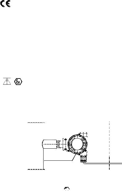
2.3. Transmitter category and hazard areas.
The category 1/2G, contained within the rating, means that the transmitter may be installed within a type 1 or 2 hazard zone. The DPC…, DPR… process connections may connect to a 0 zone type (see the diagram below for an example).
Zone 0 |
|
|
Zone 1 or 2 |
|
Safe area |
|||||||||||||||||||||||||
|
|
|||||||||||||||||||||||||||||
|
||||||||||||||||||||||||||||||
|
|
|
|
|
|
|
|
|
|
|
|
|
|
|
|
|
|
|
|
|
|
|
|
|
|
|
|
|
|
|
|
|
|
|
|
|
|
|
|
|
|
|
|
|
|
|
|
|
|
|
|
|
|
|
|
|
|
|
|
|
|
|
|
|
|
|
|
|
|
|
|
|
|
|
|
|
|
|
|
|
|
|
|
|
|
|
|
|
|
|
|
|
|
|
|
|
|
|
|
|
|
|
|
|
|
|
|
|
|
|
|
|
|
|
|
|
|
|
|
|
|
|
|
|
|
|
|
|
|
|
|
|
|
|
|
|
|
|
|
|
|
|
|
|
|
|
|
|
|
|
|
|
|
|
Pressure transmitter
or differential pressure transmitter
3. Identifying marks.
Flame-proof transmitters must have a rating plate containing the information specified in paragraph 4 of DTR.DPC.DPR.ALW.02(ENG) and also at least the following:
- CE mark and number of notified unit:, ,
 mark,
mark,
-designation of explosion protection design, certificate number,
-temperature use range,
-year of manufacture.
In place of XX letters in product rating plate will be write a pressure connection type symbols.

A |
3 |
IOM-DPCDPR-A: FEB 2014 |
|
|
Appendix Exd0.2 |
4. User information.
Together with the ordered transmitters, the user will receive:
a.Product Certificate,
b.Declaration of conformity,
c.Copy of certificate – on request
d.User’s Manual numbered: DTR.DPC.DPR.ALW.03 with Appendix Exd0.2.
User can find them b), c), d) at www.delta-controls.com
5. Power supply and exploitation of transmitters.
5.1 |
The transmitter connecting should be made after introduction with present instruction content. |
|
Electrically transmitter should be connected according to scheme at p.6 Appendix Exd. Transmitter |
i |
electrical installation should be realised with engineering standard requirements. Electrical connections |
|
of transmitters in danger zone should be made by people who have indispensable knowledge and |
|
|
|
experience in this branch. Earth clamps must be used to earth transmitters. In the event that |
|
transmitters come in contact with structural metal parts or pipes which are connected to the |
|
equipotential bonding system, transmitters do not require to be earthed. |
5.2. |
Transmitters should be supplied from DC electrical source with voltage max.45V from transformer |
i |
feeders or other devices which have at least a strengthened isolation among primary and secondary |
windings in which don’t appear voltage higher than 250V. The duty of power supply installation with |
|
|
above mentioned requirements rests on user. |
5.3.Transmitters can be use in ambient temperatures (Ta) between -40°C < Ta ≤ 45°C for T6 class or between -40°C < Ta 75°C forT5 class.
5.4.Transmitter sensor diaphragm not should be subject on damage during installation and exploitation. The diaphragm is made from 316ss or Hastelloy thin foil and cannot be subject on medium which can entail its damage.
5.5.With regard on kind of casing material (light alloy with large aluminium content), the user is obliged to
assure, that possibility of hitting casing does not step out in place of transmitter installation.
5.6.In transmitter casing are two holes to assembly of packing glands from thread M20x1,5 or 1/2 NPT.
5.7.Normally transmitters are delivered without installed glands but with blank plugs (corks) in the second
hole. They are at table 1 and table 2 at list of packing glands and plugs agreeable with production i documentation and accepted by certificate station. Customer should install packing glands according to tables 1 and plugs according to tables 2 (if plugs aren’t installed) or other accordance with flame-proof
standards.
5.8.It is necessary apply a shield cable or without shield cable with round cross-section in protection from
elastomer, not moisture absorbing, for example: YKSLY 2 * 1, YnTKSYekw 1 * 2 * 1, LIYCY 2 * In case i of need of use cable about different building customer should co-ordinate this with transmitters
manufacturer to choose intakes with cable diameter.
5.9.The general principles of connecting and the exploitation of transmitter in Exd realization should be compatible with principles and relating standards for Exd casing devices how in p.2.1, in this including also : EN600079-14, EN60079-17.
5.10.During service must be made a check of the tight fastening of covers and the packing glands and the fastening of the cable in the glands. The casing and supply line must be inspected for mechanical
idamage, and the transmitter rating plate for legibility. Periodic checks should also be made of the diaphragm, which should not carry signs of damage. During maintenance it is recommended that the threads of the covers be lubricated with non-acid vaseline.
Blocking cover method before unscrewing and plumbing possibility is shown at fig 20.
Because of the transmitter damage possibility, the ambient temperature should not be allowed to become higher than 80 C, even when there is no explosion risk.
It is not permitted to repair or otherwise interfere with the transmitter’s electrical circuits in any way. Damage estimation and repair possibility may be assessed by the manufacturer or another authorized party only.
In danger zone don’t unscrew transmitter covers and don’t change the display position or its back lighting.

A |
4 |
IOM-DPCDPR-A: FEB 2014 |
|
|
Appendix Exd0.2 |
6. How to connect Exd transmitters DPC…, DPR…
Hazardous area
short-circuit( jumper)
TEST + |
+ |
_ |
_ TEST |
|
SIGNAL |
|
|
RD


Fuse: In = 0,05A, Un = 250V according to EN 60127
|
|
|
|
Safe area |
|
|
|
|
+ |
|
|
|
|
_ |
|
|
|
|
Ro |
|
|
|
|
Ex power supply |
|
|
|
|
see p.5.. |
F1 |
F2 |
F3 |
F4 |
|
PF |
RE PV F4 |
Communicator |
||
4 |
5 |
6 |
|
|
7 |
8 |
9 |
0 |
|
|
|
|
* |
|
1 |
2 |
3 . |
|
|
Fig. 2.
In case of transmitter calibration outside danger zone is possible communicator connecting to <SIGNAL+> and <TEST+> terminals. Transmitter is furnished in communication resistor (RD = 240Ω), i closed with jumper at <SIGNAL-> and <TEST-> terminals installed by manufacturer. RD resistor can be use then, when it is necessary to communicate with transmitter from its terminals and the load resistance
(Ro) in current loop is lover then 250Ω. Than <SIGNAL-> and <TEST-> terminals have to be open.
Table 1. permitted packing glands
Type |
Producer |
|
Screw |
|
Feature |
Other marking |
No of certificate |
|
|||||
|
|
|
|
|
|
|
|
|
|
|
|
|
|
501/423 |
HAWKE |
|
M20x1,5 |
|
Exd IIC |
dimension OS, O, A |
Baseefa 06 ATEX 0056X |
|
|||||
|
|
|
|
|
|
|
|
|
|
|
|
|
|
501/421 |
HAWKE |
|
M20x1,5 |
|
Exd IIC |
dimension OS, O, A |
Baseefa 06 ATEX 0056X |
|
|||||
ICG 623 |
HAWKE |
|
M20x1,5 |
|
Exd IIC |
dimension OS, O, A |
Baseefa 06 ATEX 0058X |
|
|||||
501/453 |
HAWKE |
|
M20x1,5 |
|
Exd IIC |
dimension OS, O, A |
Baseefa 06 ATEX 0056X |
* |
|||||
|
|
|
|
|
|
|
|
|
|
|
|
|
|
501/453/RAC |
HAWKE |
|
M20x1,5 |
|
Exd IIC |
dimension OS, O, A |
Baseefa 06 ATEX 0056X |
* |
|||||
501/453/Universal |
HAWKE |
|
M20x1,5 |
|
Exd IIC |
dimension OS, O, A |
Baseefa 06 ATEX 0057X |
* |
|||||
|
|
|
|
|
|
|
|
|
|
|
|
|
|
ICG 653 |
HAWKE |
|
M20x1,5 |
|
Exd IIC |
dimension OS, O, A |
Baseefa 06 ATEX 0058X |
* |
|||||
|
|
|
|
|
|
|
|
|
|
|
|
|
|
8163/2-A2F |
STAHL |
|
M20x1.5 |
|
EXd IIC |
|
|
SIRA06ATEX1188X |
|
||||
|
|
|
|
|
|
|
|
|
|
|
|
|
|
A2F, A2FRC, SS2K |
CMP- |
|
M20x1,5 |
|
Exd IIC |
|
|
SIRA06ATEX1097X |
|
||||
Products |
|
|
|
|
|
||||||||
|
|
|
|
|
|
|
|
|
|
|
|
||
E1FW, E1FX/Z, |
CMP- |
|
M20x1,5 |
|
Exd IIC |
|
|
SIRA06ATEX1097X |
* |
||||
E2FW, E2FX/Z |
Products |
|
|
|
|
||||||||
|
|
|
|
|
|
|
|
|
|
|
|||
T3CDS, T3CDSPB |
CMP- |
|
M20x1,5 |
|
Exd IIC |
|
|
SIRA06ATEX1283X |
* |
||||
Products |
|
|
|
|
|||||||||
|
|
|
|
|
|
|
|
|
|
|
|
||
PX2K, PXSS2K, |
CMP- |
|
M20x1,5 |
|
Exd IIC |
|
|
SIRA06ATEX1097X |
* |
||||
PX2KX, PXB2KX |
Products |
|
|
|
|
||||||||
|
|
|
|
|
|
|
|
|
|
|
|||
Table 2. permitted plugs |
|
|
|
|
|
|
|
|
|
|
|||
Type |
|
Producer |
|
Screw |
|
Feature |
|
Other marking |
No certificate |
|
|
||
|
|
|
|
|
|
|
|
|
|
|
|
||
|
|
AGRO AG |
|
M20x1,5 |
|
Exd IIC |
|
|
|
|
|
||
475 |
|
HAWKE |
|
M20x1,5 |
|
Exd IIC |
|
|
|
|
|
||
|
|
|
|
|
|
|
|
|
|
|
|
||
477 |
|
HAWKE |
|
M20x1,5 |
|
Exd IIC |
|
|
|
|
|
||
*) for special cable only.

A |
5 |
IOM-DPCDPR-A: FEB 2014 |
|
|
Appendix Exi |
II. APPENDIX Exi

 1180 DPC–2000ALW PRESSURE TRANSMITTER,
DPR-2000ALW, DPR-2200ALW, DPR-2000GALW
DIFFERENTIAL PRESSURE TRANSMITTERS,
DPR-2000YALW LEVEL PROBE,
Ex VERSION
1.Introduction
1.1.This “Appendix Exi” applies to transmitters of types DPC-2000ALW, DPR-2000ALW,
DPR-2200ALW, DPR-2000GALW and DPR-2000YALW in Ex versions only, marked on the rating plate as shown in 2.2 and denoted Ex in the Product Certificate.
1.2.The appendix contains supplementary information relating to the Ex versions of these transmitters. During installation and use of Ex transmitters, reference should be made to DTR.DPC.DPR.ALW.02(ENG) in conjunction with “Appendix Exi”.
2.Use of DPC… DPR… transmitters in danger zones.
2.1.The transmitters are produced in accordance with the requirements of the following standards
EN 60079-0:2009, EN 60079-26:2007, EN 60079-11:2012, EN 50303:2000
2.2.The transmitters may operate in areas where there is a risk of explosion, in accordance with the rating of the explosion protection design:
II 1/2G Ex ia IIC T4/T5 Ga/Gb |
|
II 1/2G Ex ia IIB T4/T5 Ga/Gb |
(version with Teflon-shielelded cable) |
II 1D Ex ia IIIC T105 C Da |
|
I M1 Ex ia I Ma |
(version with enclosure ss316) |
FTZÚ |
|
2.3. Transmitter category and hazard areas
The category 1/2G, contained within the rating, means that the transmitter may be installed within a type 1 or 2 hazard zone. The DPC…, DPR… process connections may connect to a 0 zone type (see the diagram below for an example).
|
|
|
|
|
|
|
|
|
|
|
|
|
|
|
|
|
|
|
|
|
|
|
|
|
|
|
|
|
|
|
|
|
|
|
|
|
|
|
|
|
|
|
|
|
|
|
|
|
|
|
|
|
|
|
|
|
|
|
Zone 0 |
|
|
|
Zone 1 or 2 |
|
|
|
|
|
|
Safe area |
|||||||||||||||||||||||||||||||||||||||||||||||
|
|
|
|
|
|
|||||||||||||||||||||||||||||||||||||||||||||||||||||
|
|
|
|
|
|
|
|
|
|
|
|
|
|
|
|
|
|
|
|
|
|
|
|
|
|
|
|
|
|
|
|
|
|
|
|
|
|
|
|
|
|
|
|
|
|
|
|
|
|
|
|
|
|
|
|
|
|
|
|
|
|
|
|
|
|
|
|
|
|
|
|
|
|
|
|
|
|
|
|
|
|
|
|
|
|
|
|
|
|
|
|
|
|
|
|
|
|
|
|
|
|
|
|
|
|
|
|
|
|
|
|
|
|
|
|
|
|
|
|
|
|
|
|
|
|
|
|
|
|
|
|
|
|
|
|
|
|
|
|
|
|
|
|
|
|
|
|
|
|
|
|
|
|
|
|
|
|
|
|
|
|
|
|
|
|
|
|
|
|
|
|
|
|
|
|
|
|
|
|
|
|
|
|
|
|
|
|
|
|
|
|
|
|
|
|
|
|
|
|
|
|
|
|
|
|
|
|
|
|
|
|
|
|
|
|
|
|
|
|
|
|
|
|
|
|
|
|
|
|
|
|
|
|
|
|
|
|
|
|
|
|
|
|
|
|
|
|
|
|
|
|
|
|
|
|
|
|
|
|
|
|
|
|
|
|
|
|
|
|
|
|
|
|
|
|
|
|
|
|
|
|
|
|
|
|
|
|
|
|
|
|
|
|
|
|
|
|
|
|
|
|
|
|
|
|
|
|
|
|
|
|
|
|
|
|
|
|
|
|
|
|
|
|
|
|
|
|
|
|
|
|
|
|
|
|
|
|
|
|
|
|
|
|
|
|
|
|
|
|
|
|
|
|
Pressure transmitter or differential
pressure transmitter
3. Identifying marks.
Intrinsically safe transmitters must have a rating plate containing the information specified in paragraph 4 of DTR.DPC.DPR.ALW.03 and also at least the following:
CE mark and number of notified body:, , |
mark |
designation of explosion protection design, certificate number
values of parameters such as. Ui, Ii, Pi, Ci, Li
year of manufacture
"SC Version" - transmitters version with lowered values of Ci=2,5nF and Li=18µH.
"SC, SA Version" - separate power supply for transmitters with surge arresters. Power supply must be separate to earth.

A |
6 |
IOM-DPCDPR-A: FEB 2014 |
|
|
Appendix Exi |
4. User information.
Together with the ordered transmitters, the user will receive:
Product Certificate,
Declaration of conformity,
Copy of certificate – on request
User’s Manual numbered: DTR.DPC.DPR.ALW.03 with Appendix Exi.
User can find them at www.delta-controls.com
5.Permitted input parameters (based on data from the FTZÚ certificate, and certification documentation).
The transmitters should be powered via the associated power feeding and measurement devices provided with the relevant intrinsic-safe certificates. The parameters of their outputs to the danger zone should not exceed the limit power supply parameters for the below specified transmitters.
5.1 - for power supply with a “linear“ characteristic
Ui = 28V Ii = 0,1A Pi = 0,7W for Ta ≤ 70°C i T5
Power supply with a “linear” characteristic may be e.g. a typical barrier with parameters Uo = 28V Io = 0.093A Rw = 300Ω.
transmitter
Ii |
Rw |
I D |
Io
Uo
Fig.1. Power supply from a source with “linear” characteristic
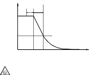
5.2. - for power supply with a “trapezial” characteristic
Ui = 24V Ii = 50mA Pi = 0,7W |
for Ta ≤ 80°C and T5 |
Example of power supply from a source with “trapezial” characteristic (see Fig. 2).
transmitter
Ii |
Io |
Rw I D |
Ui |
Uo |
Uq |
|
|
Fig. 2. Power supply from a source with “trapezial” characteristic |
||||||||
If Uo < Uq |
then parameters Uq, Io, Po are interrelated as follows: |
|
||||||||
2 |
|
|
|
|
|
Uo(Uq – Uo) |
|
|||
|
|
4Po |
|
Uq |
|
|
||||
|
|
|
|
|
|
|
|
|||
Uq = |
Io |
, |
Rw = Io |
, |
Po = |
|
|
for Uo ≤ 1/2Uq |
||
Rw |
||||||||||
|
|
|
|
|
|
|
|
|||
5.3. - for power supply with “rectangular” characteristic |
|
|||||||||
Ui = 24V |
Ii = 25mA |
|
Pi = 0,6W for Ta ≤ 80°C and T5 |
|
||||||
Ui = 24V |
Ii = 50mA |
|
Pi = 1,2W for Ta ≤ 80°C and T4 |
|
||||||
The supply of power from a source with a “rectangular” characteristic means that the voltage of the Ex power supply remains constant until current limitation activates.
The protection level of power supplies with a “rectangular” characteristic is normally “ib”. The transmitter powered from such a supply is also a Ex device with protection level “ib”.
Example of practical provision of power supply.
– use a stabilized power supply with Uo=24V with protection level „ib” and current limited to Io=25mA.
5.4. Input inductance and capacity |
Ci = 20nF, |
Li = 1,1mH |
b) Ci=2,5nF, Li=18µH – for „Version SC” |
|
|

A |
|
7 |
IOM-DPCDPR-A: FEB 2014 |
|
|
|
Appendix Exi |
5.5. Temperature of measured medium can not cause increase temperature housing of transmitter above |
|||
the ambient temperature Ta specified for a given category |
|
||
5.6. Supply voltage min. 13,5VDC ** |
|
||
5.7. Load resistance: |
|
||
from 28V linear supply |
|
||
Ro max [Ω] = |
28V – 13.5V** – (300Ω* * 0,02A) |
for transmitter without display back lighting |
|
|
|
0,0225A |
|
from a source with “trapezial” or “rectangular” characteristic supply |
|||
Ro max [Ω] = |
Usup. – 13.5V |
|
|
0,0225A |
|
||
|
|
|
|
*) |
barrier resistance |
|
|
**) |
16,5V for transmitter with display back lighting |
|
|
6. How to connect Ex transmitters DPC…, DPR…
The transmitter and other devices in the measuring loop should be connected in accordance with the intrinsic-safety and explosion-safety regulations and the conditions for use in dangerous areas.
Failure to observe the intrinsic-safety regulations can cause explosion and the resulting hazard to people.
Hazardous area |
Safe area |
|
|
Ex-Milliammeter |
|
|
|
|
|
|
|
mA |
|
|
Jumper |
|
|
|
+ |
|
|
|
|
|
|
|
_ |
|
|
_ |
_ TEST |
|
|
|
Ro |
TEST + |
+ |
|
|
|
a Ex power supply |
||
|
SIGNAL |
|
|
|
|
see p.5. |
|
|
|
RD |
|
|
|
|
|
|
|
|
|
|
|
|
|
|
|
|
F1 |
F2 |
F3 |
F4 |
Delta Controls KAP-03Ex Communicator |
|
|
|
7 |
8 |
9 |
0 |
|
|
|
|
Aplisens KAP-03Ex Communicator |
||||
|
|
|
PF |
RE PV |
F4 |
|
|
|
|
|
4 |
5 |
6 |
|
|
|
|
|
1 |
2 |
3 . |
|
|
To measure the current in the transmitter without disconnecting the signalling circuit, connect
a milliammeter to control sockets TEST+, TEST-.
In hazardous areas, connections to the control terminals must be made using only instruments which
are permitted to be used in such areas.
The transmitter is equipped in additional communication resistor RD = 240Ω During normal operation terminals <Signal –> and <Test –> are shorted.
RD resistor is used when you wish to communicate with the transmitter locally (from its terminals) and Ro < 250 . Terminals <Signal –> and <Test –> must be opened.
Transmitter electrical installation should be realised with engineering standard requirements.
It is not allowed to repair or otherwise interfere with the transmitter’s electrical circuits in any way. Damage and possible repair may be assessed only by the manufacturer or another authorized party.
Special conditions for safe use:
- Version of transmitter with surge arrester, marked on the plate "SC, SA", does not meet the requirements of Section 10.3 of the EN 60079-11:2012 (500Vrms). This must be taken into account when installing the equipment.

A |
8 |
IOM-DPCDPR-A: FEB 2014 |
1. INTRODUCTION
1.1. This Manual is intended for users of DPC-2000ALW smart pressure transmitters, DPR-2000ALW, DPR2200ALW, DPR-2200GALW smart differential pressure transmitters, and DPR-2000YALW smart level probe and their intrinsic-safety versions, containing the data and guidelines necessary to understand the functioning of the transmitters and how to operate them. It includes essential recommendations concerning installation and use, as well as emergency procedures. The parameters and information specified for transmitters identified herein with the sign DPC..., DPR... also apply to transmitters: DPC-2000ALW, DPR-2000ALW, DPR-2200ALW, DPR-2200GALW, DPR-2000YALW and their explosion-proof versions, as well as all the variations differing by the type of the process terminals. Information on the transmitter sizes and the method of installation apply to both, all versions of transmitters.
1.2.Technical data for the diaphragm seals and for the DPC... and DPR... transmitters are contained in the catalogue cards “DIAPHRAGM SEALS”.
1.3.The transmitters comply with the requirements of EU directives as shown on the plate and with the relevant Declaration of Conformity.
1.4.Additional data on DPC-2000ALW, DPR-2000ALW, DPR-2200ALW, DPR-2000GALW and
DPR-2000YALW transmitters in Ex versions is contained in the appendix designed to DTR.DPC.DPR.ALW.02(ENG). Exi Appendix and in Exd versions in the appendix designed to
DTR.DPC.DPR.ALW.02(ENG). Exd Appendix.
During installation and use of the transmitters in Ex or Exd version, reference should be made to
DTR.DPC.DPR.ALW.02(ENG) in conjunction with Exi or Exd Appendix.
2. USER MATERIALS
Transmitters are delivered in single and/or multiple packs. Together with the transmitter are delivered:
a)Product certificate, which is also as the warranty card
b)Declaration of conformity - on request
c)Copy of ATEX certificate – on request,
d)User’s Manual numbered: DTR.DPC.DPR.ALW.02(ENG).
Items b), c), d) are available at: www.delta-controls.com
3. APPLICATIONS AND MAIN FEATURES
3.1. The DPC... smart pressure transmitters are designed to measure gauge pressure, vacuum pressure and absolute pressure of gases, vapours and liquids (including corrosive substances).
Differential pressure transmitters type DPR… are used to measure liquid levels in closed tanks, with static pressure up to 25MPa, or 32MPa for special versions and to measure differential pressure across constrictions such as filters and orifices.
3.2. The transmitters may be fitted with a range of types of process connectors, which enables them to
ibe used in a variety of conditions such as thick or highly reactive media, high and low temperatures, etc.
3.3.DPC..., DPR... transmitters generate a 4...20mA output signal and a digital communication signal in a twowire system (current loop). The use of smart electronics enables regulation of the zero point, the measurement
range, damping, radical conversion characteristic and other functions using an Delta Controls KAP communicator or from a PC using a Hart/RS232 converter and Delta Controls “D-Soft” configuration software.
A |
9 |
IOM-DPCDPR-A: FEB 2014 |
4. IDENTIFYING MARKS. ORDERING PROCEDURE
4.1. Every transmitter carries a rating plate containing at least the following information: CE mark, manufacturer name, transmitter type, serial number, pressure range, static pressure limit, output signal, power supply voltage.
Version types and the method of specifying the desired product are described in the current “Information Cards” and the Catalogue.
4.2. DPC...DPR...transmitters in Ex version or Exd version have additional markings as described in DTR.DPC.DPR.ALW.02(ENG) Appendix Exi or Exd.
i |
4.4. DPC...DPR... transmitters in realization for sea uses have additional information about signs |
|
|
|
Location Classe and DNV Certificate No. A-11308. |
5.TECHNICAL DATA.
5.1. DPC..., DPR...- Common parameters
5.1.1. DPC..., DPR... Electrical parameters
Power supply |
12* ÷ 55V DC |
Power supply for intrinsic-safe versions |
in accordance with Appendix Exi. |
Output signal |
4÷20mA + Hart rev.5.1 |
Communication |
realised via a 4÷20mA signal using KAP-03 communicator |
|
or RS/Hart modem and PC computer with “D-Soft” software |
Resistance for communication |
|
|
250÷1100Ω, min 240Ω |
|
|
|
|
|
|
|||||||
Load resistance |
|
|
|
|
|
RLmax[Ω] = |
Usup[V]-12V* |
|
|
|
|
|
||||
|
|
|
|
|
0,0225A |
|
|
|
|
|
||||||
|
|
|
|
|
|
|
|
|
|
|
|
|
|
|||
Usuply min. = 12*+ 0,0225xRL [V] |
|
|
|
|
|
|
|
|
|
|
|
|
||||
*) 15V |
for transmitters with display backlight. |
|
|
|
|
|
|
|
|
|
|
|||||
|
Umin = f(Ro) z podświetleniem |
|
|
|
|
|
|
|
Umin = f(Ro) bez podświetlenia |
|
|
|
|
|
||
55 |
|
|
|
|
|
|
|
55 |
|
|
|
|
|
|
|
|
50 |
|
|
|
|
|
|
|
50 |
|
|
|
|
|
|
|
|
45 |
|
|
|
|
|
|
|
45 |
|
|
|
|
|
|
|
|
40 |
|
|
|
|
|
|
|
40 |
|
|
|
|
|
|
|
|
35 |
|
|
|
|
|
|
|
35 |
|
|
|
|
|
|
|
|
[V] 30 |
|
|
|
|
|
|
|
[V] 30 |
|
|
|
|
|
|
|
|
Vmin 20 |
|
|
|
|
|
|
|
Vmin 20 |
|
|
|
|
|
|
|
|
25 |
|
|
|
|
|
|
|
25 |
|
|
|
|
|
|
|
|
15 |
|
|
|
|
|
|
|
15 |
|
|
|
|
|
|
|
|
10 |
|
|
|
|
|
|
|
10 |
|
|
|
|
|
|
|
|
0 |
250 |
500 |
750 |
1000 |
1250 |
1500 |
1750 |
0 |
|
250 |
500 |
750 |
1000 |
1250 |
1500 |
1750 |
|
|
|
Ro[ ] |
|
|
|
|
|
|
|
|
Ro[ ] |
|
|
|
|
Safe working area (grid) upper colour area. |
|
|
|
|
|
|
|
|
|
|
||||||
Output updating time |
|
|
|
500ms |
|
|
|
|
|
|
|
|
|
|||
Additional electronic damping |
|
|
0...30s |
|
|
|
|
|
|
|
|
|
||||
Voltage for insulation testing |
|
|
500 VAC or 750 VDC, |
see p.9.3. |
|
|
|
|
|
|||||||
Excess voltage protection |
|
|
see p.9.3. |
|
|
|
|
|
|
|
|
|
||||
A |
10 |
IOM-DPCDPR-A: FEB 2014 |
Response time on pressure stroke.
|
wyłączenie |
|
|
ciśnieniapressure |
|
I |
switch off |
|
|
td = 10 - 250ms |
|
|
|
|
|
td |
tc |
20mA |
|
t c = 200ms |
|
|
|
|
|
t r = t d + t c |
|
|
t r min. = 210ms |
|
|
t r max. = 460ms |
9.89mA |
|
|
4mA |
|
|
DPC...DPR...transmitter, response time on pressure stroke tr measuring cycle 0,5s , damping = 0.
t
5.1.2. DPC..., DPR... Permitted environmental conditions
Operating temperature range |
-40°C ÷ 85°C |
Operating temperature range for intrinsic-safe versions in accordance with Appendix Exi Operating temperature range for flame-proof versions in accordance with Appendix Exd
Medium temperature range |
-40°C ÷ 120°C – for direct measurement, |
|
over 120°C measurement with a transmission |
|
tube or diaphragm seal using |
for intrinsic-safe versions |
in accordance with Appendix Exi. |
Thermal compensation range |
-25º ÷ 80ºC, |
|
(-40º ÷ 80ºC for special version DPC...) |
Relative humidity |
max. 98% |
5.1.2.1. Electromagnetic Compatibility (EMC), immunity
Rating according to EN 61326-1,2for industrial applications
Electrostatic Discharge Immunity (ESD):
EN 61000-4-2; S3 level: contact ±6kV, air ±8kV; criterion A
Conducted Radio Frequency:
EN 61000-4-6; 0,15… 80MHz, 10V; criterion A
Radiated electromagnetic Field:
EN 61000-4-3; 80… 2 000MHz – 10V/m, 2 000 … 2 700MHz – 1V/m; criterion A
Electrical Fast Transient (Burst Immunity)
EN 61000-4-4; ± 2kV power supply port/earth, ± 1kV signal port/earth; criterion A
Electrical Slow Transient (Surge Immunity):
EN 61000-4-5; ±0.5kV (±1kV) 0,5kV differentia mode, 1kV common mode; criterion B
5.1.2.2. Electromagnetic Compatibility, emission:
According to CISPR16-1, CISPR 16-2, class B, distance to the antenna 3m, quasi-peak measuring:
Radiated emission: 0,15 … 30MHz, 80-52dBμV/m;
30 … 2000MHz, <54dBμV/m
Conducted emission: 0,01 … 0,150MHz, 96-50dBμV/m;
0,150 … 0,350MHz, 60-50dBμV/m;
0,35 … 30MHz, <50dBμV/m
A |
11 |
IOM-DPCDPR-A: FEB 2014 |
5.1.2.3. Climatic immunity: dry heat, cold, humidity, salt mist:
Dry heat:
EN 60068-2-2, test B; T = 700C, RH = max 55%
Cold :
EN 60068-2-1, test A; T = -250C,
Damp heat cycle:
EN 60068-2-30, test D ; (T = 550C, RH = min95%, 24h)x2
Salt mist:
EN 60068-2-52; (spraying: 2h duration, T = 250C, storage in damp chamber: 7 days, T = 400C, RH = 93%)x4, 28days total
5.1.2.4. Mechanical immunity
Shocks:
EN 60068-2-27, 50g/11ms
Vibrations:
EN 60068-2-6, test Fc; up to 1,6mm for 2 … 25Hz, up to 4g for 25 … 100Hz
5.1.3.1. Insulation Resistance
>100 MΩ @110V transmitters with gas arresters
>100 MΩ @750V DC transmitters without gas arresters
5.1.3.2. High Voltage Test
500V AC, or 750V DC, 1min, transmitters without gas arresters 75V AC, or 110V DC, 1min, transmitters with gas arresters
5.1.4. Enclosure ingress protection
EN 60529, IP 66,67
5.1.5. DPC..., DPR... Construction materials
Diaphragm seal for DPC... |
Stainless steel 316L |
(00H17N14M2) or Hastelloy C276 |
Diaphragm seal for DPR... |
Stainless steel 316L |
(00H17N14M2) or Hastelloy C276 |
Sensing module |
Stainless steel 316L |
(00H17N14M2) |
Liquid filling the interior the sensing module |
Silicone oil, chemically inactive liquid for measurement of |
|
oxygen uses. |
Connectors for DPC... |
Stainless steel 316L (00H17N14M2) or |
|
Hastelloy C276 only for P, GP, CM30x2 |
C-type vented covers and connectors for DPR.. Stainless steel 316L (00H17N14M2)
Electronics casing High pressure cast of aluminium alloy, lacquered with chemical-resistant oxide enamel, colour yellow (RAL 1003).

A |
|
|
|
|
|
|
|
|
12 |
|
|
IOM-DPCDPR-A: FEB 2014 |
|||
5.2. DPC...- Measurement ranges and metrological parameters. |
|
|
|||||||||||||
5.2.1. DPC..., Measurement ranges |
|
|
|
|
|
|
|
||||||||
|
|
|
|
|
|
|
|
|
|
||||||
N |
|
Nominal measuring range |
Minimum set range |
Rangeability |
|
Overpressure limit |
|
||||||||
|
|
|
(FSO) |
|
|
(without hysteresis) |
|
||||||||
|
|
|
|
|
|
|
|
|
|
|
|||||
1. |
0... |
1000bar |
|
(0... |
100MPa) |
10bar |
(1MPa) |
100:1 |
|
1200bar |
(120MPa) |
|
|||
2. |
0... |
300bar |
|
(0... |
30MPa) |
3bar |
(300kPa) |
100:1 |
|
450bar |
(45MPa) |
|
|||
3. |
0... |
160bar |
|
(0... |
16MPa) |
1,6bar |
(160kPa) |
100:1 |
|
450bar |
(45MPa) |
|
|||
4. |
0... |
70bar |
|
(0... |
7MPa) |
0,7bar |
(70kPa) |
100:1 |
|
140bar |
(14MPa) |
|
|||
5. |
0... |
25bar |
|
(0... |
2,5MPa) |
0,25bar |
(25kPa) |
100:1 |
|
50bar |
(5MPa) |
|
|||
6. |
0... |
7bar |
|
(0... |
0,7MPa) |
0,07bar |
(7kPa) |
100:1 |
|
14bar |
(1,4MPa) |
|
|||
7. |
-1... |
6bar |
(-100... |
600kPa) |
300mbar |
(30kPa) |
23:1 |
|
14bar |
(1,4MPa) |
|
||||
8. |
0... |
2bar |
|
(0... |
200kPa) |
100mbar |
(10kPa) |
20:1 |
|
4bar |
(400kPa) |
|
|||
9. |
0... |
1bar |
|
(0... |
100kPa) |
50mbar |
(5kPa) |
20:1 |
|
2bar |
(200kPa) |
|
|||
10. |
-0,5... |
0,5bar |
|
(-50... |
50kPa) |
50mbar |
(5kPa) |
20:1 |
|
2bar |
(200kPa) |
|
|||
11. |
0... |
0,25bar |
|
(0... |
25kPa) |
25mbar |
(2,5kPa) |
10:1 |
|
1bar |
(100kPa) |
|
|||
12. |
-100 100mbar (-10 10kPa)... ... |
20mbar |
(2kPa) |
10:1 |
|
1bar |
(100kPa) |
|
|||||||
13. |
-15... |
70mbar* |
(-15... |
7kPa) |
5mbar |
(0,5kPa) |
17:1 |
|
0,5bar |
(50kPa) |
|
||||
14. |
-7... |
7 mbar* |
(-700... |
700Pa) |
1mbar |
(0,1kPa) |
14:1 |
|
0,5bar |
(50kPa) |
|
||||
15. |
0... |
1,3bar abs |
(0... |
110kPa abs) |
50mbar abs |
(5kPa abs) |
26:1 |
|
2bar |
(200kPa) |
|
||||
16. |
0... |
7bar abs |
|
(0... |
7MPa abs) |
0,07bar abs |
(7kPa abs) |
100:1 |
|
14bar |
(1,4MPa) |
|
|||
17. |
0... |
25bar abs |
(0... |
2,5MPa abs) |
0,25bar abs (25kPa abs) |
100:1 |
|
50bar |
(5MPa) |
|
|||||
18. |
0... |
70bar abs |
(0... |
7MPa abs) |
0,7bar abs (70kPa abs) |
100:1 |
|
140bar |
(14MPa) |
|
|||||
* - only for transmitters without diaphragm seal, |
|
|
|
|
|
|
|
||||||||
5.2.2. DPC..., Metrological parameters
Accuracy
Long term stability
Error due to supply voltage changes Thermal error
Thermal error for the whole thermal compensation range
max ± 0,075% for the basic range (0,16% for range 14)accuracy for 3 years (for the nominal measuring range) max ± 0,002%(FSO)/1V
max ± 0,08%(FSO)/10ºC
max ± 0,1% FSO/10 C for n°12, 13, 14 ranges. max ± 0,25%(FSO)
(max ± 0,4% FSO/10 C for n°12, 13, 14 ranges.
5.2.3. DPC..., Pressure Connectors
M-type connector with M20x1.5 thread – see figure 5a, P-type connector with M20x1.5 thread – see figure 6a, CM30x2-type connector with flush diaphragm – see figure 7a, G1/2 -type connector with G1/2” thread – see figure 8a,
GP -type connector with G1/2” thread,
CG1-type connector with G1” thread and flush diaphragm – see figure 8e, RM-type connector with M20x1.5 thread and radiator
RP-type connector with M20x1.5 thread and radiator

A 13 IOM-DPCDPR-A: FEB 2014 G1/4-type connector with G1/4 thread,
1/2"NPT -type connector with 1/2"NPT tread, R1/2-type connector with R1/2 tread,
CG1/2-type connector with G1/2 tread and flush diaphragm, other connection types by arrangement.
5.3. DPR-2000ALW, DPR-2200ALW Measurement ranges and metrological parameters.
5.3.1. DPR-2000ALW, Measurement ranges
N |
Nominal measuring range |
Minimum set range |
Rangeability |
Overpressure |
Static pressure |
||||
(FSO) |
limit |
|
limit |
||||||
|
|
|
|
|
|||||
1 |
0...16bar |
(0...1,6MPa) |
1,6bar |
(160kPa) |
10:1 |
|
|
|
|
2 |
0...2,5bar |
(0...250kPa) |
0,25bar |
(25kPa) |
10:1 |
|
|
|
|
3 |
0...1bar |
(0...100kPa) |
70mbar |
(7kPa) |
14:1 |
|
250, 320bar |
||
4 |
0...0,25bar |
(0...25kPa) |
10mbar |
(1kPa) |
25:1 |
|
|||
(40bar for P-type connector) |
|||||||||
5 |
-100...100mbar |
(-10...10kPa) |
4mbar |
(0,4kPa) |
50:1 |
||||
|
|
|
|||||||
6 |
-5...70mbar |
(-0,5...7kPa) |
4mbar |
(0,4kPa) |
18:1 |
|
|
|
|
7 |
-0,5...0,5bar |
(-50...50kPa) |
0,1bar |
(10kPa) |
10:1 |
|
|
|
|
8 |
-25...25mbar |
(-2,5...2,5kPa) |
2,5mbar |
(0,25kPa) |
20:1 |
|
20 bar |
||
5.3.2. DPR-2200ALW, Measurement ranges
Nominal range |
Minimum set |
Vertical spacing |
Maximum configurable range dependent |
Static |
|
of diaphragm |
on the actual vertical spacing of |
pressure |
|||
(FSO) |
range |
||||
seals. |
diaphragm seals. (m) |
limit |
|||
|
|
||||
-160...160 mbar |
0,1 mH2O |
1,7m |
[1,6+( vertical spacing of sealsx94)]mH2O |
40bar |
|
-0,5...0,5 bar |
0.5 mH2O |
6m |
[5+(vertical spacing of sealsx1,04)]mH2O |
40bar |
|
-1,6...2 bar |
1,5 mH2O |
15m |
[20+(vertical spacing of sealsx1,04)]mH2O |
40bar |
|
-1,6...16 bar |
1bar |
15m |
16bar |
40bar |
The maximum vertical diaphragm seal spacing shown in the table applies to level measurement, i ensuring that it is possible to set the zero point of the transmitter when the tank is empty.
For measurements of density or phase boundaries (in the sugar and chemical industries and in refineries) the vertical spacing of the diaphragm seals can be larger.
5.3.3. DPR-2000ALW, DPR-2200ALW Metrological parameters
Accuracy |
± 0,075% (FSO) for the DPR-2000ALW nominal range |
|
Long term stability |
accuracy / 3 years |
|
Error due to supply voltage changes |
± 0,002%(FSO)/1V |
|
Thermal error |
± 0,08%(FSO)/10ºC |
|
Thermal error for the whole thermal |
|
|
compensation range |
± 0,3%(FSO) |
|
Zero shift error for static pressure* |
± 0,08 % |
(FSO)/10bar |
|
± 0,01 % |
(FSO)/10bar (for range n°4) |
|
± 0,03 % |
(FSO)/10bar (for range n°5, 6) |
Cut-off on radical characteristic curve |
up to10% of flow. |
|
* zeroing in static pressure conditions with zero differential pressure eliminate this error.
5.3.4. DPR-2000ALW, Pressure Connectors
DPR-2000/ALW– C-type connector to mount together with a valve manifold see fig.9,
DPR-2000/ALW with single direct diaphragm seal – as in the example (fig.10) or with other diaphragm seals in accordance with “DIAPHRAGM SEALS” catalogue cards.
5.3.5. DPR-2200ALW. Pressure Connectors - diaphragm seals – see “DIAPHRAGM
SEALS ”catalogue cards.

A |
14 |
IOM-DPCDPR-A: FEB 2014 |
5.4. DPR–2000GALW, Measurement ranges and metrological parameters.
5.4.1 DPR–2000GALW. Measurement ranges
N |
Nominal range |
Minimum set range |
Overpressure |
Static pressure limit |
|||
(FSO) |
limit |
||||||
|
|
|
|
||||
1 |
0...25mbar |
(0...2500Pa) |
1mbar |
(100Pa) |
1bar |
350mbar |
|
2 |
-2,5...2,5mbar |
(-250...250Pa) |
0,2mbar |
(20Pa) |
350mbar |
350mbar |
|
3 |
-7...7mbar |
(-700...700Pa) |
1mbar |
(100Pa) |
350mbar |
350mbar |
|
4 |
-25...25mbar (-2500...2500Pa) |
5mbar |
(500Pa) |
1bar |
1bar |
||
5 |
-100...100mbar |
(-10...10Pa) |
20mbar |
(2kPa) |
1bar |
1bar |
|
5.4.2. DPR–2000GALW. Metrological parameters.
Nominal range |
0...25mbar |
-2,5...2,5mbar |
-7...7mbar |
-25...25mbar |
-100...100mbar |
|
Accuracy |
0,075 % |
0,16 % |
0,1 % |
0,1 % |
0,075 % |
|
Thermal error |
0,1 % (FSO)/ 10 C, max 0,4 % (FSO) for the whole thermal compensation |
|||||
|
|
|
range |
|
|
|
|
|
|
|
|
|
|
Thermal compensation range |
|
|
-10 … 700C |
|
||
Additional electronic damping |
|
|
0...60 s |
|
||
5.4.3. DPR–2000GALW. Construction materials
M20x1,5/ 6x1 adapter |
brass |
Valve manifold |
ss316L |
Valve manifold adapter |
ss316L |
¼ NPT connector |
brass, ss316L or galvanized St3S carbon steel |
(Other materials as given in 5.1.3 for DPR...).
5.4.4. DPR–2000GALW. Pressure Connectors
-The terminals fit adapted to ø 6x1 plastic tubes,
-Valve manifold adapter or ¼ NPT connector- (see p. 8.3. and fig.17).
5.5. DPR–2000YALW. Measurement ranges and metrological parameters.
5.5.1. DPR–2000YALW. Measurement ranges.
N |
1 |
2 |
Nominal range |
0... – 6000 mmH2O |
0... – 1600 mmH2O |
Minimum set range |
600 mmH2O |
160 mmH2O |
Static pressure limit |
40 bar |
|
5.5.2. DPR–2000YALW. Metrological parameters.
Nominal range N |
1 |
2 |
Accuracy for basic range |
± 0,16 % |
± 0,2 % |
Accuracy for minimum range |
± 0,5 % |
± 0,6 % |
temperature error |
0,4 % for temperatures –25...+80°C |
|
Zero shift error from static pressure * |
0,08 % / 10bar |
0,1 % / 10bar |
* zeroing in static pressure conditions with zero differential pressure eliminate this error. Medium density range – up to 1,1 g/cm3 – (standard version)
– over 1,1 g/cm3 – (special version by arrangement with DELTA CONTROLS)
 Loading...