


Note: Rockler may not carry all products and/or sizes listed in this vendor's publication
12" Bench Drill Press
(w/Laser Guides)
(Model DP300L)
21450
RTD10000255AA
PART NO. A14210-10-27-05 Rev. B
Copyright © 2005 Delta Machinery
|
|
|
|
To learn more about DELTA MACHINERY |
|
|
|
ESPAÑOL: PÁGINA 21 |
|
||
visit our website at: www.deltamachinery.com. |
FRANÇAISE : PAGE 41 |
|
|
For Parts, Service, Warranty or other Assistance, |
|
||
|
|
||
please call 1-800-223-7278 (In Canada call 1-800-463-3582).
MANUAL INSTRUCTION

TABLE OF CONTENTS
IMPORTANT SAFETY INSTRUCTIONS . . . . . . . . . . . . . . . . . . . . . . . . . . . . . . . . . . . . . . . . . . . . . . . . . . . . . . . . . . . 2 SAFETY GUIDELINES - DEFINITIONS . . . . . . . . . . . . . . . . . . . . . . . . . . . . . . . . . . . . . . . . . . . . . . . . . . . . . . . . . . . 3 TOOL WARNING LABEL . . . . . . . . . . . . . . . . . . . . . . . . . . . . . . . . . . . . . . . . . . . . . . . . . . . . . . . . . . . . . . . . . . . . . . 3 GENERAL SAFETY RULES . . . . . . . . . . . . . . . . . . . . . . . . . . . . . . . . . . . . . . . . . . . . . . . . . . . . . . . . . . . . . . . . . . . . 4 ADDITIONAL SPECIFIC SAFETY RULES . . . . . . . . . . . . . . . . . . . . . . . . . . . . . . . . . . . . . . . . . . . . . . . . . . . . . . . . . 5 ADDITIONAL SAFETY RULES FOR THE LASER . . . . . . . . . . . . . . . . . . . . . . . . . . . . . . . . . . . . . . . . . . . . . . . . . . . 6 FUNCTIONAL DESCRIPTION . . . . . . . . . . . . . . . . . . . . . . . . . . . . . . . . . . . . . . . . . . . . . . . . . . . . . . . . . . . . . . . . . . 8 CARTON CONTENTS . . . . . . . . . . . . . . . . . . . . . . . . . . . . . . . . . . . . . . . . . . . . . . . . . . . . . . . . . . . . . . . . . . . . . . . . . 9 ASSEMBLY . . . . . . . . . . . . . . . . . . . . . . . . . . . . . . . . . . . . . . . . . . . . . . . . . . . . . . . . . . . . . . . . . . . . . . . . . . . . . . . . 10 OPERATION . . . . . . . . . . . . . . . . . . . . . . . . . . . . . . . . . . . . . . . . . . . . . . . . . . . . . . . . . . . . . . . . . . . . . . . . . . . . . . . 14 MAINTENANCE. . . . . . . . . . . . . . . . . . . . . . . . . . . . . . . . . . . . . . . . . . . . . . . . . . . . . . . . . . . . . . . . . . . . . . . . . . . . . 20 SERVICE . . . . . . . . . . . . . . . . . . . . . . . . . . . . . . . . . . . . . . . . . . . . . . . . . . . . . . . . . . . . . . . . . . . . . . . . . . . . . . . . . . 20 ACCESSORIES . . . . . . . . . . . . . . . . . . . . . . . . . . . . . . . . . . . . . . . . . . . . . . . . . . . . . . . . . . . . . . . . . . . . . . . . . . . . . 20 WARRANTY. . . . . . . . . . . . . . . . . . . . . . . . . . . . . . . . . . . . . . . . . . . . . . . . . . . . . . . . . . . . . . . . . . . . . . . . . . . . . . . . 20
IMPORTANT SAFETY INSTRUCTIONS
 Read and understand all warnings and operating instructions before using any tool or equipment. When using tools or equipment, basic safety precautions should always be followed to reduce the risk of personal injury. Improper operation, maintenance or modification of tools or equipment could result in serious injury and property damage. There are certain applications for which tools and equipment are designed. Delta Machinery strongly recommends that this product NOT be modified and/or used for any application other than for which it was designed.
If you have any questions relative to its application DO NOT use the product until you have written Delta Machinery and we have advised you.
Online contact form at www.deltamachinery.com
Postal Mail: Technical Service Manager Delta Machinery
4825 Highway 45 North Jackson, TN 38305
(IN CANADA: 125 Mural St. Suite 300, Richmond Hill, ON, L4B 1M4)
Information regarding the safe and proper operation of this tool is available from the following sources:
Power Tool Institute
1300 Sumner Avenue, Cleveland, OH 44115-2851 www.powertoolinstitute.org
National Safety Council
1121 Spring Lake Drive, Itasca, IL 60143-3201
American National Standards Institute, 25 West 43rd Street, 4 floor, New York, NY 10036 www.ansi.org
ANSI 01.1Safety Requirements for Woodworking Machines, and the U.S. Department of Labor regulations www.osha.gov
SAVE THESE INSTRUCTIONS!
2

SAFETY GUIDELINES - DEFINITIONS
It is important for you to read and understand this manual. The information it contains relates to protecting YOUR SAFETY and PREVENTING PROBLEMS. The symbols below are used to help you recognize this information.
Indicates an imminently hazardous situation which, if not avoided, will result in death or serious injury.
Indicates a potentially hazardous situation which, if not avoided, could result in death or serious injury.
Indicates a potentially hazardous situation which, if not avoided, may result in minor or moderate injury.
Used without the safety alert symbol indicates potentially hazardous situation which, if not avoided, may result in property damage.
CALIFORNIA PROPOSITION 65
 Sone dust created by powere sanding, sawing, grinding, drilling, and other construction activities contains chemicals known to cause cancer, birth defects or other reproductive harm. Some examples of these chemicals are:
•lead from lead-based paints,
•crystalline silica from bricks and cement and other masonry products, and
•arsenic and chromium from chemically-treated lumber.
Your risk from these exposures varies, depending on how often you do this type of work. To reduce your exposure to these chemicals: work in a well ventilated area, and work with approved safety equipment, always wear NIOSH/OSHA approved, properly fitting face mask or respirator when using such tools.
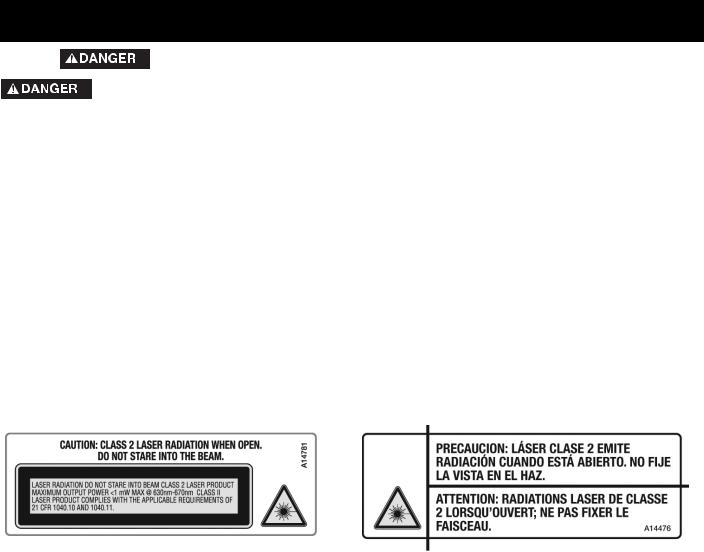
TOOL WARNING LABELS
3

GENERAL SAFETY RULES
 READ AND UNDERSTAND ALL WARNINGS AND OPERATING INSTRUCTIONS BEFORE USING THIS EQUIPMENT. Failure to follow all instructions listed below, may result in
electric shock, fire, and/or serious personal injury or property damage.
IMPORTANT SAFETY INSTRUCTIONS
1.FOR YOUR OWN SAFETY, READ THE INSTRUCTION MANUAL BEFORE OPERATING THE MACHINE. Learning the machine’s application, limitations, and specific hazards will greatly minimize the possibility of accidents and injury.
2.WEAR EYE AND HEARING PROTECTION. ALWAYS USE SAFETY GLASSES. Everyday eyeglasses are NOT safety glasses. USE CERTIFIED SAFETY EQUIPMENT. Eye protection equipment should comply with ANSI Z87.1 standards. Hearing equipment should comply with ANSI S3.19 standards.
3.WEAR PROPER APPAREL. Do not wear loose clothing, gloves, neckties, rings, bracelets, or other jewelry which may get caught in moving parts. Nonslip protective footwear is recommended. Wear protective hair covering to contain long hair.
4.DO NOT USE THE MACHINE IN A DANGEROUS ENVIRONMENT. The use of power tools in damp or wet locations or in rain can cause shock or electrocution. Keep your work area well-lit to prevent tripping or placing arms, hands, and fingers in danger.
5.MAINTAIN ALL TOOLS AND MACHINES IN PEAK CONDITION. Keep tools sharp and clean for best and safest performance. Follow instructions for lubricating and changing accessories. Poorly maintained tools and machines can further damage the tool or machine and/or cause injury.
6.CHECK FOR DAMAGED PARTS. Before using the machine, check for any damaged parts. Check for alignment of moving parts, binding of moving parts, breakage of parts, and any other conditions that may affect its operation. A guard or any other part that is damaged should be properly repaired or replaced with Delta or factory authorized replacement parts. Damaged parts can cause further damage to the machine and/or injury.
7.KEEP THE WORK AREA CLEAN. Cluttered areas and benches invite accidents.
8.KEEP CHILDREN AND VISITORS AWAY. Your shop is a potentially dangerous environment. Children and visitors can be injured.
9.REDUCE THE RISK OF UNINTENTIONAL STARTING. Make sure that the switch is in the “OFF” position before plugging in the power cord. In the event of a power failure, move the switch to the “OFF” position. An accidental start-up can cause injury. Do not touch the plug’s metal prongs when unplugging or plugging in the cord.
10.USE THE GUARDS. Check to see that all guards are in place, secured, and working correctly to prevent injury.
11.REMOVE ADJUSTING KEYS AND WRENCHES BEFORE STARTING THE MACHINE. Tools, scrap pieces, and other debris can be thrown at high speed, causing injury.
12.USE THE RIGHT MACHINE. Don’t force a machine or an attachment to do a job for which it was not designed. Damage to the machine and/or injury may result.
13.USE RECOMMENDED ACCESSORIES. The use of accessories and attachments not recommended by Delta may cause damage to the machine or injury to the user.
14.USE THE PROPER EXTENSION CORD. Make sure your extension cord is in good condition. When using an extension cord, be sure to use one heavy enough to carry the current your product will draw. An undersized cord will cause a drop in line voltage, resulting in loss of power and overheating. See
the Extension Cord Chart for the correct size depending on the cord length and nameplate ampere rating. If in doubt, use the next heavier gauge. The smaller the gauge number, the heavier the cord.
15.SECURE THE WORKPIECE. Use clamps or a vise to hold the workpiece when practical. Loss of control of a workpiece can cause injury.
16.FEED THE WORKPIECE AGAINST THE DIRECTION OF THE ROTATION OF THE BLADE, CUTTER, OR ABRASIVE SURFACE. Feeding it from the other direction will cause the workpiece to be thrown out at high speed.
17.DON’T FORCE THE WORKPIECE ON THE MACHINE.
Damage to the machine and/or injury may result.
18.DON’T OVERREACH. Loss of balance can make you fall into a working machine, causing injury.
19.NEVER STAND ON THE MACHINE. Injury could occur if the tool tips, or if you accidentally contact the cutting tool.
20.NEVER LEAVE THE MACHINE RUNNING UNATTENDED. TURN THE POWER OFF. Don’t leave the machine until it comes to a complete stop. A child or visitor could be injured.
21.TURN THE MACHINE “OFF”, AND DISCONNECT THE MACHINE FROM THE POWER SOURCE before installing or removing accessories, changing cutters, adjusting or changing set-ups. When making repairs, be sure to lock the start switch in the “OFF” position. An accidental start-up can cause injury.
22.MAKE YOUR WORKSHOP CHILDPROOF WITH PADLOCKS, MASTER SWITCHES, OR BY REMOVING STARTER KEYS. The accidental start-up of a machine by a child or visitor could cause injury.
23. STAY ALERT, WATCH WHAT YOU ARE DOING, AND USE
COMMON SENSE. DO NOT USE THE MACHINE WHEN YOU ARE TIRED OR UNDER THE INFLUENCE OF DRUGS, ALCOHOL, OR MEDICATION. A moment of inattention while operating power tools may result in injury.
24.  USE OF THIS TOOL CAN GENERATE
AND DISBURSE DUST OR OTHER AIRBORNE PARTICLES, INCLUDING WOOD DUST, CRYSTALLINE SILICA DUST AND ASBESTOS DUST.
Direct particles away from face and body. Always operate tool in well ventilated area and provide for proper dust removal. Use dust collection system wherever possible. Exposure to the dust may cause serious and permanent respiratory or other injury, including silicosis (a serious lung disease), cancer, and death. Avoid breathing the dust, and avoid prolonged contact with dust. Allowing dust to get into your mouth or eyes, or lay on your skin may promote absorption of harmful material. Always use properly fitting NIOSH/OSHA approved respiratory protection appropriate for the dust exposure, and wash exposed areas with soap and water.
4

ADDITIONAL SPECIFIC SAFETY RULES
FAILURE TO FOLLOW THESE RULES MAY RESULT IN SERIOUS INJURY.
1.DO NOT OPERATE THIS MACHINE until it is completely assembled and installed according to the instructions. A machine incorrectly assembled can cause serious injury.
2.OBTAIN ADVICE from your supervisor, instructor, or another qualified person if you are not thoroughly familiar with the operation of this machine. Knowledge is safety.
3.FOLLOW ALL WIRING CODES and recommended electrical connections to prevent shock or electrocution.
4.SECURE THE MACHINE TO A SUPPORTING SUR-FACE.
Vibration can cause the machine to slide, walk, or tip over.
5.NEVER START THE MACHINE BEFORE CLEARING THE TABLE OF ALL OBJECTS (tools, scrap pieces, etc.). Debris can be thrown at high speed.
6. NEVER START THE MACHINE with the drill bit, cutting tool, or sanding drum against the workpiece. Loss of control of the workpiece can cause serious injury.
7.PROPERLY LOCK THE DRILL BIT, CUTTING TOOL, OR SANDING DRUM IN THE CHUCK before operating this machine.
8.REMOVE THE CHUCK KEY BEFORE STARTING THE MACHINE. The chuck key can be thrown out at a high speed.
9.TIGHTEN ALL LOCK HANDLES before starting the machine. Loss of control of the workpiece can cause serious injury.
10.USE ONLY DRILL BITS, CUTTING TOOLS, SANDING DRUMS, OR OTHER ACCESSORIES with shank size recommended in your instruction manual. The wrong size accessory can cause damage to the machine and/or serious injury.
11.USE ONLY DRILL BITS, CUTTING TOOLS, OR SANDING DRUMS that are not damaged. Damaged items can cause malfunctions that lead to injuries.
12. USE RECOMMENDED SPEEDS for all operations. Other speeds may cause the machine to malfunction causing damage to the machine and/or serious injury.
13.AVOID AWKWARD OPERATIONS AND HAND POSITIONS. A sudden slip could cause a hand to move into the bit.
14. KEEP ARMS, HANDS, AND FINGERS away from the bit. Serious injury to the hand can occur.
15.HOLD THE WORKPIECE FIRMLY AGAINST THE TABLE. Do not attempt to drill a workpiece that does not have a flat surface against the table, or that is not secured by a vise. Prevent the workpiece from rotating by clamping it to the table or by securing it against the drill press column. Loss of control of the workpiece can cause serious injury.
16.TURN THE MACHINE “OFF” AND WAIT FOR THE DRILL BIT, CUTTING TOOL, OR SANDING DRUM TO STOP TURNING prior to cleaning the work area, removing debris, removing or securing work-piece, or changing the angle of the table. A moving drill bit, cutting tool, or sanding drum can cause serious injury.
17.PROPERLY SUPPORT LONG OR WIDE work-pieces. Loss of control of the workpiece can cause severe injury.
18.NEVER PERFORM LAYOUT, ASSEMBLY OR SET-UP WORK on the table/work area when the machine is running. Serious injury can result.
19.TURN THE MACHINE “OFF”, disconnect the machine from the power source, and clean the table/work area before leaving the machine. LOCK THE SWITCH IN THE “OFF” POSITION to prevent unauthorized use. Someone else might accidentally start the machine and cause serious injury to themselves.
20.ADDITIONAL INFORMATION regarding the safe and proper operation of power tools (i.e. a safety video) is available from the Power Tool Institute, 1300 Sumner Avenue, Cleveland, OH 44115-2851 (www. powertoolinstitute.com). Information is also available from the National Safety Council, 1121 Spring Lake Drive, Itasca, IL 60143-3201. Please refer to the American National Standards Institute ANSI 01.1 Safety Requirements for Woodworking Machines and the U.S. Department of Labor OSHA 1910.213 Regulations.
SAVE THESE INSTRUCTIONS.
Refer to them often
and use them to instruct others.
5
ADDITIONAL SAFETY RULES FOR THE LASER
FAILURE TO FOLLOW THESE RULES MAY RESULT IN SERIOUS INJURY.
EYE INJURY -LASER LIGHT
*Do not stare into beam aperture, or into a reflection from a mirror-like surface
*Do not use optical tools such as a telescope or transit to view the laser beam
 EYE INJURY - LASER LIGHT
*Do not operate the laser around children or allow children to operate the laser.
*Store idle laser out of reach of children and other untrained persons
*Turn the laser off when it is not in use
*Do not disassemble laser module. The class II laser output could be exceeded if the unit is disassembled. Laser complies with 21 CFR 1040.10 and 1040.11.
 USE OF CONTROLS OR ADJUSTMENTS OR PERFORMANCE OF PROCEDURES OTHER THAN THOSE SPECIFIED HEREIN MAY RESULT IN HAZARDOUS RADIATION EXPOSURE.
 EXPLOSION HAZARD. Do not operate the laser or drill press in explosive atmospheres such as in the presence of flammable liquids, gases, or dust. A spark could ignite the dust or fumes.
NOTE: Do not remove or deface warning labels.
6
POWER CONNECTIONS
A separate electrical circuit should be used for your machines. This circuit should not be less than #12 wire and should be protected with a 20 Amp time lag fuse. If an extension cord is used, use only 3-wire extension cords which have 3-prong grounding type plugs and matching receptacle which will accept the machine’s plug. Before connecting the machine to the power line, make sure the switch (s) is in the “OFF” position and be sure that the electric current is of the same characteristics as indicated on the machine. All line connections should make good contact. Running on low voltage will damage the machine.
 ELECTROCUTION HAZARD. DO NOT EXPOSE THE MACHINE TO RAIN OR OPERATE THE MACHINE IN DAMP LOCATIONS.
MOTOR SPECIFICATIONS
Your machine is wired for 120 Volts 60 HZ alternating current. Before connecting the machine to the power source, make sure the switch is in the “OFF” position.
GROUNDING INSTRUCTIONS
 ELECTROCUTION HAZARD. THIS MACHINE MUST BE GROUNDED WHILE IN USE TO PROTECT THE OPERATOR FROM ELECTRIC SHOCK.
1.All grounded, cord-connected machines:
In the event of a malfunction or breakdown, grounding provides a path of least resistance for electric current to reduce the risk of electric shock. This machine is equipped with an electric cord having an equipment-grounding conductor and a grounding plug. The plug must be plugged into a matching outlet that is properly installed and grounded in accordance with all local codes and ordinances.
Do not modify the plug provided - if it will not fit the outlet, have the proper outlet installed by a qualified electrician.
Improper connection of the equipment-grounding conduc-tor can result in risk of electric shock. The conductor with insulation having an outer surface that is green with or without yellow stripes is the equipment-grounding conductor. If repair or replacement of the electric cord or plug is necessary, do not connect the equipment-grounding conductor to a live terminal.
Check with a qualified electrician or service personnel if the grounding instructions are not completely understood, or if in doubt as to whether the machine is properly grounded.
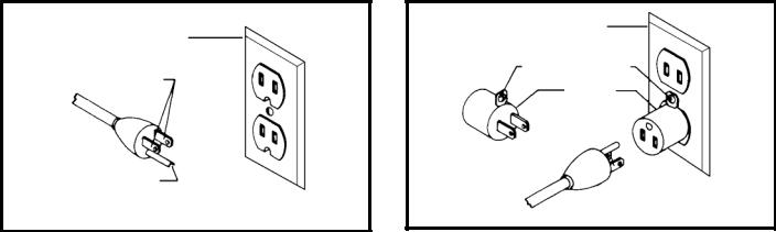
Use only 3-wire extension cords that have 3-prong grounding type plugs and matching 3-conductor receptacles that accept the machine’s plug, as shown in Fig. A.
Repair or replace damaged or worn cord immediately.
2.Grounded, cord-connected machines intended for use on a supply circuit having a nominal rating less than 150 volts:
If the machine is intended for use on a circuit that has an outlet that looks like the one illustrated in Fig. A, the machine will have a grounding plug that looks like the plug illustrated in Fig. A. A temporary adapter, which looks like the adapter illustrated in Fig. B, may be used to connect this plug to a matching 2-conductor receptacle as shown in Fig. B if a properly grounded outlet is not available. The temporary adapter should be used only until a properly grounded outlet can be installed by a qualified electrician. The green-colored rigid ear, lug, and the like, extending from the adapter must be connected to a permanent ground such as a properly grounded outlet box. Whenever the adapter is used, it must be held in place with a metal screw.
NOTE: In Canada, the use of a temporary adapter is not permitted by the Canadian Electric Code.
 ELECTROCUTION HAZARD. IN ALL CASES, MAKE CERTAIN THAT THE RECEPTACLE IN QUESTION IS PROPERLY GROUNDED. IF YOU ARE NOT SURE, HAVE A QUALIFIED ELECTRICIAN CHECK THE RECEPTACLE.
|
GROUNDED OUTLET BOX |
||
GROUNDED OUTLET BOX |
|
|
|
CURRENT |
GROUNDING MEANS |
||
|
|
|
|
CARRYING |
|
|
|
|
ADAPTER |
|
|
PRONGS |
|
|
|
|
|
|
|
|
|
|
|
GROUNDING BLADE
IS LONGEST OF THE 3 BLADES
Fig. A |
Fig. B |
7

EXTENSION CORDS
 USE PROPER EXTENSION CORDS. MAKE SURE YOUR EXTENSION CORD IS IN GOOD CONDITION AND IS A 3-WIRE EXTENSION CORD WHICH HAS A 3-PRONG GROUNDING TYPE PLUG AND MATCHING RECEPTACLE WHICH WILL ACCEPT THE MACHINE’S PLUG. WHEN USING AN EXTENSION CORD, BE SURE TO USE ONE HEAVY ENOUGH TO CARRY THE CURRENT OF THE MACHINE. AN UNDERSIZED CORD WILL CAUSE A DROP IN LINE VOLTAGE, RESULTING IN LOSS OF POWER AND OVERHEATING. FIG. D-1 SHOWS THE CORRECT GAUGE TO USE DEPENDING ON THE CORD LENGTH. IF IN DOUBT, USE THE NEXT HEAVIER GAUGE. THE SMALLER THE GAUGE NUMBER, THE HEAVIER THE CORD.
MINIMUM GAUGE EXTENSION CORD
RECOMMENDED SIZES FOR USE WITH STATIONARY ELECTRIC MACHINES
|
|
Total |
|
|
Ampere |
|
Length of |
|
|
|
Cord in |
|
Gauge of Extension |
|
|
|
|
||
Rating |
Volts |
Feet |
|
Cord |
0-6 |
120 |
up to 25 |
|
18 AWG |
0-6 |
120 |
25-50 |
|
16 AWG |
0-6 |
120 |
50-100 |
|
16 AWG |
0-6 |
120 |
100-150 |
|
14 AWG |
6-10 |
120 |
up to 25 |
|
18 AWG |
6-10 |
120 |
25-50 |
|
16 AWG |
6-10 |
120 |
50-100 |
|
14 AWG |
6-10 |
120 |
100-150 |
|
12 AWG |
10-12 |
120 |
up to 25 |
|
16 AWG |
10-12 |
120 |
25-50 |
|
16 AWG |
10-12 |
120 |
50-100 |
|
14 AWG |
10-12 |
120 |
100-150 |
|
12 AWG |
12-16 |
120 |
up to 25 |
|
14 AWG |
12-16 |
120 |
25-50 |
|
12 AWG |
12-16 |
120 |
GREATER THAN 50 FEET NOT RECOMMENDED |
||
|
|
Fig. D-1 |
|
|
FUNCTIONAL DESCRIPTION
FOREWORD
The Delta DP300L 12" Drill Press comes with a flexible work lamp, a laser guide for precise drilling and a utility tray for keeping tools within easy reach. This machine has a tilting table for angle drilling and side edges and parallel slots for fast workpiece clamping.
NOTICE: The photo on the manual cover illustrates the current production model. All other illustrations contained in the manual are representative only and may not depict the actual labeling or accessories included. These are are intended to illustrate technique only.
8
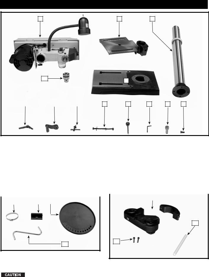
CARTON CONTENTS
1 |
|
2 |
|
3 |
13
4
12 |
|
11 |
|
10 |
|
9 |
|
8 |
|
7 |
|
6 |
|
5 |
1. |
Drill Press Head and Motor |
10. |
Chuck Key |
|||||||||
2. |
Table |
|
|
|
|
|
11. |
Table Raising and Lowering Handle |
||||
3. |
Column, Base Flange and Rack |
12. |
Table Clamp |
|||||||||
4. |
Base |
|
|
|
|
|
13. |
Chuck |
||||
5. |
M8x1.25x25mm Hex Head Cap Screws (4) |
14. |
Clamp |
|||||||||
6. |
Worm Gear for Table Raising and Lowering |
15. |
Mounting bracket |
|||||||||
7. |
Hex Wrenches (2) |
|
|
|
|
16. |
Tray |
|||||
8. |
Pinion Shaft Handles (3) |
17. |
Mounting arm |
|||||||||
9. |
M8x1.25x125mm Carriage Head Screws (2), M8 |
18. |
Laser |
|||||||||
|
Flat Washers (2), M8.1 Lock Washers (2), M8x1.25 |
19. |
Laser Alignment Rod |
|||||||||
|
Hex Nuts (2) (for fastening the base to a supporting |
20. Hex Head Cap Screws (2) |
||||||||||
|
surface) |
|
|
|
|
|
||||||
|
|
|
|
|
|
|
|
|
|
|||
|
|
|
|
|
|
|
|
|
|
|
|
|
|
|
|
|
|
|
|
|
|
|
|
18 |
|
|
|
|
|
|
|
|
|
|
|
|||
|
|
14 |
|
15 |
|
16 |
|
|
|
|
|
|
19
20
17
UNPACKING AND CLEANING
Carefully unpack the machine and all loose items from the shipping container(s). Remove the rust-preventative oil from unpainted surfaces using a soft cloth moistened with mineral spirits, paint thinner or denatured alcohol.
DO NOT USE HIGHLY VOLATILE SOLVENTS SUCH AS GASOLINE, NAPHTHA, ACETONE OR LACQUER THINNER FOR CLEANING YOUR MACHINE.
After cleaning, cover the unpainted surfaces with a good quality household floor paste wax.
9
ASSEMBLY
For your own safety, do not connect the machine to the power source until the machine is completely assembled and you read and understand the entire instruction manual.
ASSEMBLY TOOLS REQUIRED
Hex Wrenches - (supplied)
1/2 open end wrench - (not supplied)
ASSEMBLY TIME ESTIMATE
Assembly for this machine takes approximately 15 to 30 minutes.
E |
D |
A |
F |
B |
C |
|
Fig. 3 |
J |
|
G 

Fig. 5
K
J

 F
F
H
G
Fig. 4
F |
I |
G |
Fig. 6 |
F |
L |
Fig. 7 |
|
|
|
Fig. 8 |
|
|
|
|
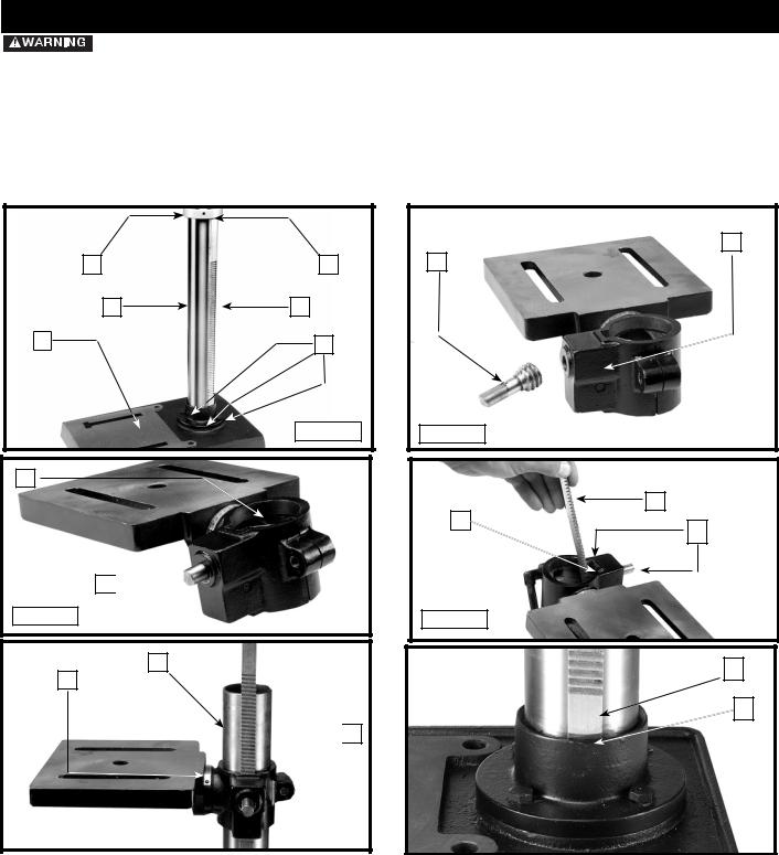
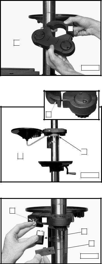
1.Attach the column (A) Fig. 3 to the base (B) using the four M8x1.25x25mm hex head screws (C), three of which are shown. Loosen the set screw (D) and remove the ring (E) and raising rack (F).
2.Place the worm gear (G) Fig. 4 in the table bracket (H).
NOTE: Place the small end of the worm gear (G) Fig. 5 in the hole (J), then into the hole for the worm gear. The correct placement is shown in Fig. 5.
3. Insert the raising rack (F) Fig. 6 (removed in STEP 1) in the table bracket groove (I).
NOTE: Place the teeth of the raising rack (F) in the teeth of the worm gear (G) located inside table bracket.
4.Slide the raising rack (F) Fig. 7 and the table with the table bracket (J) on the drill press column (K) Fig. 7. NOTE: Place the bottom of the raising rack (F) Fig. 8 inside the flange (L) on the drill press base.
5.Place the mounting bracket (A) Fig. 10 on the column.
NOTE: Make sure the mounting bracket (A) Fig. 10 is on the opposite side of the column from the raising rack (F) Fig. 8.
10
6.Insert the clamp (B) Fig. 10 through the mounting bracket, under the raising rack, and around the column. Tighten the hose clamp securely.
7.Assemble the mounting arm (C) into the bracket hole (D) Fig. 10 and attach tray (T) to the mounting arm.
8.Be sure the bracket, mounting arm and raising rack are positioned in relation to the drill press table as shown in Fig. 9.
9.Install the ring (E) Fig. 11 (removed in STEP 1) on the column.
IMPORTANT: Place the raising rack under the bottom of the ring, but allow enough clearance so that the rack
(F) can rotate around the column. Tighten the set screw
(D) Fig. 11.
10.Attach the table raising and lowering handle (K) Fig. 12 on the worm gear shaft (G) and tighten the set screw (L) against the flat on the shaft.
11.Thread the stud of the clamp handle (M) Fig. 13 in the hole in the rear of the table bracket.
C
D 

B 

T
Fig. 10 |
A |

 G
G
L
K 
Fig. 12
Fig. 9
E |
D |
Fig. 11
M 

Fig. 13
11
 EYE INJURY - LASER LIGHT. DO NOT STARE INTO THE LASER BEAM OR APERTURE OR INTO A REFLECTION FROM A
MIRROR-LIKE SURFACE.
12.Screw front laser housing (A) Fig. 14 to the rear laser housing (B) loosely using the two socket head cap screws (C) Fig. 14A inset included in laser packaging.
13.Place this laser housing assembly onto the drill press column (D) Fig. 14A and rest it on the collar
(E) Fig. 14A.
14.Tighten the screws (C) Fig. 14A inset, making sure the laser housing is positioned so that one laser is to each side of the column (D), as shown in Fig 14A.
15.Remove battery cover (F) Fig. 14B from laser housing.
16.Connect a 9-volt battery (G) (not included) onto the battery terminal (H).
17.Place battery into the compartment (I) and replace the cover.
B
A 

Fig. 14
C

 E D
E D 
Fig. 14A
H |
I |
G |
F |
Fig. 14B |
12
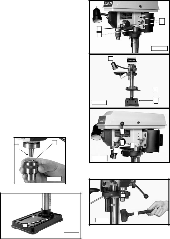
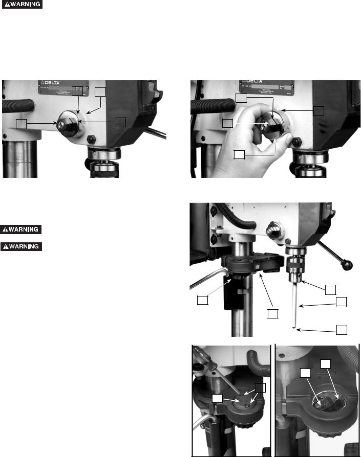
18.Seat the drill press head (N) Fig. 15 on the column
(U). Align the head (A) Fig. 15A, with the table (B) and base (C). Tighten the two head locking screws (O) Fig. 15 with the supplied wrench.
19.Thread the three pinion shaft handles (P) Fig. 16 in the three tapped holes located in the pinion shaft
(S).
NOTE: Make certain that the spindle taper (Q) Fig. 17 and the tapered hole in the chuck (R) are clean and free of grease, lacquer, or rust preventive coatings.
NOTE: Household oven cleaner can effectively remove any substance from the spindle and chuck. Carefully follow the manufacturer's safety rules concerning its use.
20.Open the chuck jaws as wide as possible by turning the chuck sleeve (N) Fig. 18. Hold the chuck on the taper of the spindle and tap with a rubber mallet (T) or a block of wood and hammer to set the chuck (Fig. 18).
IMPORTANT: To avoid damage to the chuck, DO NOT drive the chuck on the spindle with a metal hammer.
FASTENING DRILL PRESS TO
SUPPORTING SURFACE
If, during operation, the machine has a tendency to tip over, slide, or walk on the supporting surface, secure the machine base to the supporting surface with an M8x1.25x125mm carriage head screw, 8.5mm flat washer, 8.5mm lock washer, M8x1.25 hex nut through the two holes (A) Fig. 19 located in the machine base.
R |
Q |
Fig. 17 |
A
Fig. 19
13
O
N |
U |
Fig. 15 |
A 


 B
B
C
Fig. 15A
P
S
P
P
Fig. 16 |
N
T
Fig. 18
OPERATION
OPERATIONAL CONTROLS AND ADJUSTMENTS
STARTING AND STOPPING THE DRILL PRESS
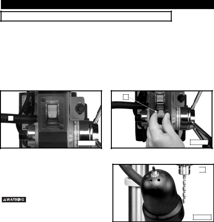
1.The on/off switch (A) Fig. 20 is located on the front of the drill press head. To turn the machine "ON", move the switch up to the "ON" position.
2.To turn the machine "OFF", move the switch (A) down to the "OFF" position.
 Make sure that the switch is in the "OFF" position before plugging in the power cord. In the event of a power failure, move the switch to the "OFF" position. An accidental start-up can cause injury.
LOCKING SWITCH IN THE "OFF" POSITION
IMPORTANT: When the tool is not in use, the switch should be locked in the "OFF" position to prevent unauthorized use. To lock the machine, grasp the switch toggle (B) Fig. 21 and pull it out of the switch. With the switch toggle (B) removed, the switch will not operate. However, should the switch toggle be removed while the saw is running, the machine can be turned "OFF," but cannot be restarted without re-inserting the switch toggle (B).
A 

Fig. 20
FLEXIBLE LAMP
The flexible lamp operates independently of the drill press. To turn the lamp “ON” and “OFF”, rotate switch
(A) Fig. 22.
Fire Hazard. To reduce the risk of fire, use 40 watt or less, 120 volt, reflector track-type light bulb (not supplied). DO NOT use a standard household light bulb. The reflector track-type light bulb should not extend below the lamp shade.
B
Fig. 21

 A
A
Fig. 22
14

TABLE ADJUSTMENTS
1.Raise or lower the table on the column by loosening the table clamp (A) Fig. 23, and turning the table raising and lowering handle (B) Fig. 24. After the table is at the desired height, tighten the clamp (A) Fig. 23.
NOTE: Always raise (rather than lower) the table to the final position to allow the gears to mesh and prevent slippage.
2. The table can be rotated 360 degrees on the column by loosening the clamp (A) Fig. 23, rotating the table to the desired position, and tightening the clamp (A).
D 

C 


 E
E
Fig. 25
3.The table can be tilted right or left by removing the table alignment pin (C) Fig. 25.
NOTE: If the pin (C) is difficult to remove, turn the nut (E) clockwise to pull the pin out of the casting.
4.Loosen the table locking bolt (D) Fig. 26, tilt the table to the desired angle, and tighten the bolt (D). When you return the table to the level position, replace the table alignment pin (C) Fig. 25 to position the table surface 90 degrees to the spindle.
5.A tilt scale (E) Fig. 27 is provided on the table bracket casting to indicate the degree of tilt. A witness line and zero mark (F) are also provided on the table to align with the scale (E).
A
Fig. 23
B
Fig. 24
C
D 
Fig. 26
F |
E |
|
|
|
Fig. 27 |
15
A
SPINDLE |
MOTOR |
|
|
E |
|||
|
|
3100
2340
1720
1100 C
620
D
B
Fig. 28 |
Fig. 29 |
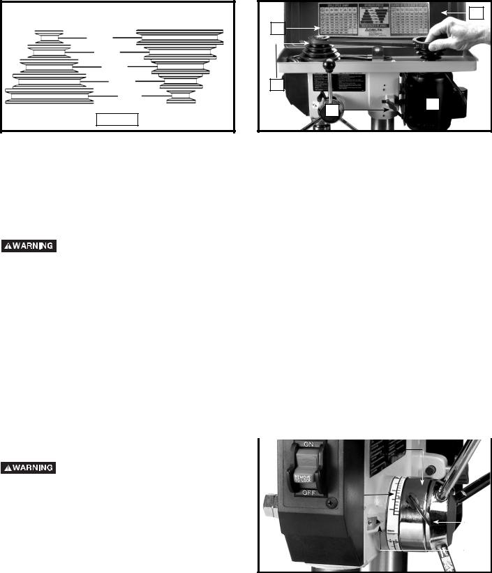
SPINDLE SPEEDS
Five spindle speeds (620, 1100, 1720, 2340, and 3100 RPM) are available with your drill press. See the chart in Fig. 28 to select the correct belt placement for your project.
CHANGING SPEEDS AND ADJUSTING BELT TENSION
NOTE: A belt-positioning speed chart (E) Fig. 29 is located on the inside top cover of the drill press.
Disconnect machine from power source.
1.Open the top cover (A) Fig. 29.
2.Loosen the tension lock knob (B) Fig. 29 to release belt tension. Pivot the motor (D) toward the front of the drill press.
3.Hold the motor in this position and place the belt (C) on your selected speeds according to the chart in Fig. 28.
4.Move the motor to the rear until the belt has proper tension.
NOTE: The belt should be just tight enough to prevent slipping. Excessive tension will reduce the life of the belt, pulleys and bearings. Correct tension is obtained when the belt (C) can be flexed about 1" out of line midway between the pulleys using light finger pressure.
5. Tighten the tension lock knob (B).
DRILLING HOLES TO DEPTH
A depth stop is provided in the pinion shaft housing to |
|
|
|
|
|
|
|
|
|
|
allow you to drill any number of holes to the same depth. |
|
|
|
|
|
|
|
|
|
|
|
|
|
|
|
|
|
|
|
||
To use: |
|
|
|
|
|
B |
|
|||
|
Disconnect machine from power |
|
|
|
|
|
|
|
|
|
|
source. |
|
|
|
|
|
|
|
|
|
|
|
|
|
|
|
|
|
|
|
|
1. |
Insert the bit into the chuck. |
|
|
|
D |
|
|
|
|
|
|
|
|
|
|
|
|
|
|
||
2. |
Lower the spindle until the pointer (C) Fig. 30 aligns |
|
|
|
|
|
|
|
|
|
|
|
|
|
|
|
|
A |
|
||
|
with the your selected mark on the scale (D). |
|
|
|
|
|
|
|
|
|
|
|
|
|
|
|
|
|
|
|
|
3. |
Tighten the lock screw (A). |
|
|
|
|
|
|
|
|
|
4. |
Return the spindle to the up position. |
|
|
|
|
|
|
|
C |
|
|
Fig. 30 |
|
|
|
|
|
|
|
||
|
|
|
|
|
|
|
|
|
|
|
5.Place the workpiece on the drill press table. Raise the drill press table until the workpiece touches the drill bit.
6.Drill a test hole to check the depth.
NOTE: Scale (D) is calibrated in both inches and millimeters.
16
ADJUSTING SPINDLE RETURN SPRING
The spindle will automatically return slowly to its upper position when the handle is released. The spindle return spring was properly adjusted at the factory. However, to adjust, if necessary:
Disconnect machine from power source.
1.Loosen the nuts (B) and (E) Fig. 31. Make sure that the spring housing (A) remains engaged with head casting (C).
2.While firmly holding the spring housing (A) Fig. 32, pull out the housing and rotate it (counter-clockwise to increase or clockwise to decrease the spring tension) until the boss (D) is engaged with the next notch on the housing. Turn the nut (E) until it contacts the spring housing (A), then back the nut (E) out 1/4 turn from the spring housing (A). Tighten the nut (B) against the nut (E) to hold the housing in place.
IMPORTANT: The inside nut (E) should not contact spring housing (A) when tightened.
|
|
|
|
|
|
|
|
|
|
|
|
|
|
|
|
|
|
|
|
|
|
|
|
|
|
|
A |
|
|
|
|
|
|
|
|
|
|
|
|
|
|
|
|
|
|
|
|
|
|
C |
|
|
|
|
|
|
|
|
|
|
|
|
|||
|
|
|
|
|
|
|
|
|
E |
|
|
|
|
|
|
||||||
|
|
|
|
|
|
|
|
|
|
|
|
|
|
|
|
|
|||||
|
|
|
|
|
|
|
|
|
|
|
|
|
|
|
|
|
|
|
|
|
|
|
|
|
|
|
|
|
|
|
|
|
|
|
|
|
|
|
|
|
|
|
|
|
|
|
|
|
|
|
|
|
|
|
|
|
|
|
|
|
|
D |
|
||
|
|
|
|
|
|
|
|
|
|
|
|
|
|
|
|
|
|
|
|
|
|
|
|
|
|
|
|
|
|
|
E |
|
|
|
|
|
|
|
|
|
|
|
|
|
|
B |
|
|
|
|
|
|
|
B |
|
|
|||||||||
|
|
|
|
|
|
|
|
|
|
|
|
|
|||||||||
|
|
|
|
|
|
|
|
|
|
|
|||||||||||
|
|
|
|
|
|
|
|
|
|
|
|
|
|
|
A |
||||||
|
|
|
|
|
|
|
|
|
|
|
|
|
|
|
|
|
|
|
|
|
|
|
|
|
|
|
|
|
|
|
|
|
|
|
|
|
|
|
|
|
|
Fig. 32 |
|
|
Fig. 31 |
|
|
|
|
|
|
|
|
||||||||||||
|
|
|
|
|
|
|
|
|
|
|
|
|
|
|
|
|
|
|
|
|
|
|
|
|
|
|
|
|
|
|
|
|
|
|
|
|
|
|
|
|
|
|
|
ADJUSTING LASERS
Disconnect machine from power source.
Laser Light. Do not stare into the beam, aperture, or into a reflection from a
mirror-like surface.
MAKING LASERS PARALLEL
1.Install alignment pin (A) into chuck (B). Make sure that the pointed end (C) of the alignment pin is down, as shown in Fig. L1. The black scribed line on the pin should face towards the left laser.
2.Turn on lasers using switch (D) on the front of the laser housing.
3.With a Phillips head screwdriver, remove the two screws (F) Fig. L2 and cap (G) above the left side of laser housing.
4.Loosen the laser retainer screw (H) Fig. L3.
5.Move the laser lever (I) Fig. L3 so the laser is shining on the alignment pin. Adjust the lever (I) until the laser is parallel with the black line.
NOTE: It may be necessary to move the laser holder (J) Fig. L1 to get the laser to shine on the alignment pin. Once the light is on the pin, adjust the laser with the lever (I).
6.When laser is set, tighten the laser retainer screw (H) Fig. L3. Then, replace the cap (G) Fig L2 and loosely tighten the two screws (F).
7.Repeat for the right side.
MAKING LASERS INTERSECT
|
|
|
|
|
|
|
|
|
|
|
|
|
|
|
|
|
|
|
|
|
|
|
|
B |
|
|
|
|
|
J |
|
|
|
|
|
|
|
|
|
|
|
|
|
|
|
|
|
|
|
|
|
|
A |
|
|
|
|
|
|
|
|
|
|||||||
|
|
|
|
|
|
D |
|
||||||
|
|
|
|
|
|
|
|
|
|
|
|
|
|
|
|
Fig. L1 |
|
|
|
|
|
|
|
|
|
C |
|
|
|
|
|
|
|
|
|
|
|
|
|
|
|
|
|
|
|
|
|
|
|
|
|
|
|
|
|
|
|
|
|
|
|
|
|
|
|
|
|
|
|
|
|
|
|
|
|
|
|
|
I |
||||
|
|
|
|
|
|
|
|
|
H |
||||
|
|
|
|
|
|||||||||
|
|
|
|
F |
|
||||||||
|
|
G |
|
|
|
|
|
|
|
|
|
|
|
Fig. L2 |
|
Fig. L3 |
17
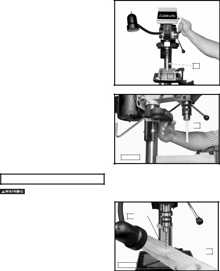
1.Place a piece of wood (K) Fig. L4 on the table and clamp in place.
2.Rotate quill (M) down and make an indention in the wood with the alignment pin (L) Fig. L4.
3.Turn on laser and adjust both beams to cross that point by rotating the laser holder (J) Fig. L5.
4.Check if the lasers line up at different heights by either raising or lowering the table, making a new indention and turning on the lasers to verify they cross at the indention. If the laser does not align at different heights, the parallel adjustment needs to be readjusted.
5.Once the lasers are adjusted, tighten the screws on each side of the laser housing, two of which are shown at (F) Fig. L2.
M
L
|
|
K |
|
Fig. L4 |
|||
|
|

 J
J
Fig. L5
MACHINE USE
The use of accessories and attachments not recommended by Delta may result in risk of injury.
B 

 A
A
Fig. 33
NOTE: Use scrap material for practice to get a feel of the machine before attempting regular work.
18
 Loading...