

Page 1
CONDIZIONATORI / AIRCONDITIONERS / KLIMAGERÄTE
CLIMATISEURS D’AIR / ACONDICIONADORES DE AIRE
DE’LONGHI PAC 16E
DATI TECNI CI / TECHNICAL DATA / TECHNISCHE DATEN
DONNEES TECHNIQUES / DAT OS TECNICOS
Tensione / Voltage / Spannung / Tension / Tension V / Hz 220 … 240 / 50
Condizionamento / Condi t i oning / Klimatisierung / Cli m at i sation / Acondicionamiento
Max. potenza assorbita / M ax. input power / M ax. Leist ungsauf nahm e W 850
Max. puissance absorbée / Max. pot encia absorbida
Potenza di raffreddament o / Cooling capacity / Kühlleistung W 1905*
Puissance de climatisation / Potencia de acondicionamiento
Riscaldamento / Heat i ng / Hei z ung / Chauf f age / Cal efación
Potenza di riscaldamento / Heating capacity / Heizleistung W 2000
Puissance de chauffage / Potencia de calefación
Compress o re / Compress o r / K o mpressor / Compre s s eur / Compres s o r Type LG QB114PL12A
avvolgimento / winding / W i cklung / bobinage / envolvimiento (Start/Run) Ω 6.8 / 4.8
- prote ttore termico / the rma l prote cto r / thermi sche Sic her ung Typ e MRA12060
protecteur ther m ique / pr ot ect or t ér m ico (Off-On).°C 150 - 69
- condensatore / capacitor / Kondensator / condensateur / condensador µF25
(INT)
Ventilatore / Ventilator / Vent ilator / Vent ilateur / Vent ilador Type EMO D4E160 ECE
-GN46-07 4-KDN-017
- avvolgimento / winding / Wicklung / Start (Blue - Brown) Ω 268.8 143.5
bobinage / envolvimiento Run (Blue – Black)Ω 168 141.5
- potenza assorbita / input power / Leist ungsauf nahm e W 93 60
puissance absorbé / potencia assorbida
- condensatore / capacitor / Kondensat or / condensateur / condensador µF2 3
Termostato / Ther m ost at / Thermostat / Ther m ost at / Termostato Type Elettronico / Electronic
- temperatur a / temperature / Tem per atur / températ ur e / temperatura °C 16– 32 (cool) / 8-25 (heat) ∆T 0.8°C
Sonda / Probe / Fühler / Sonde / Sonda Type / °C=KΩ NTC / 0°C=27.3KΩ – 25°C = 10KΩ
Pressostato (acqua) / Pressostat (water) / Druckschalter ( W asser ) Type ELBI
Pressostat (eau) / Pr essost at o ( agua)
- attacco-stacco / on-off / ein-aus / marche-ar r et / cerrado-abierto mmH20 150 – 115
Pompa acqua / Water pump / Wasserpumpe / Type ASKOLL 291041
Pompe de l'eau / Bomba agua
- avvolgimento / winding / Wicklung / bobinage / envolvimiento Ω 778
- potenza assorbita / input power / Leist ungsauf nahm e W 5
puissance absorbée / potencia absorbida
Trasformator e / Trasformer / Tr ansformer Primario 220 VAC
Tranformateur / Transformador Secondario 12 VAC
Interrutt or e / Switch / Schalter / Inter r upteur / Interr uptor V/A 250 / 16 (10)
Dati di pressione / Pr essur es dat a / Druck Dat en / Caractéristi ques de pression / Datos de presión
Alta pressione / High pressure side / Hoher Druck / Haute pression / Alta pr esión bar 21.6**
Bassa pressione / Low pressure side / Niedriger Druck / Basse pression / Baja presión bar 5.64**
Carica freon / Freon charge / Fr eon M enge / Quantité du Fréon / Carga de f reon (R22) gr 490
* ASHRAE 129P
** ATTENTION:
Tutti i dati dichiarati sono relativ i a: / All data are referred to : / Alle Daten beziehen sich auf:
Toutes les données regardents à: / Todos los datos se refieren a:
Temperatura ambiente Room temperature Raumtemperatur Température dans la piéce Temperatura ambiente 27 °C
Temperatura esterna Outdoor temperature Außentemperatur Température externe Temperature externa 35 °C
Umidità relativa Relativ e humidity Relativ e Feuchtigkeit Humidité relative Humidad relativa 50 %
SCHEDA TECNICA 99024
Page 2
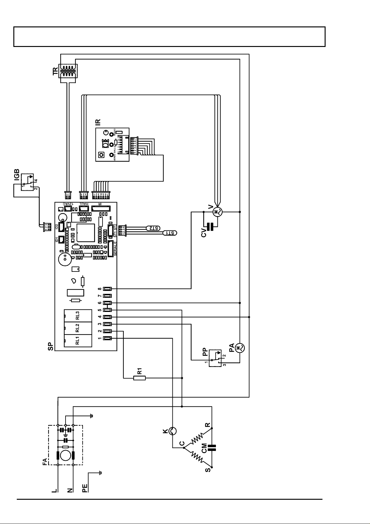
II. SCHEMA ELETTRICO / ELECTRICAL DIAGRAM / SCHALTPLAN
SCHEMA ELECTRIQUE / SCHEMA ELECTRICO
Legenda
Condensador CSR
Compressore
Condensador ventilador
Filtro
Microinterruptor max. nivel de agua
Ficha recividora
Protector CSR
Bomba agua
Pressostato bomba
Resistencia
Ficha de potencia
Sonda de temperatura
Sonda evaporador
Transformador
Ventilador
Legende
Condensateur CSR
Compresseur
Condensateur ventilateur
Filtre
Microinterrupteur max. neiveau de l'eau
C.i. de reception
Protecteur CSR
Pompe dé l'eau
Zeichenerklärung
Kondensator CSR
Kompressor
Kondensator Ventilator
Entstörfilter
Max. Wasserniveau-Mikroschalter
Empfängerplatine
Kompressorschutz
Wasserpumpe
Legend
CSR capacitor
Compressore
Ventilator capacitor
Antinoise filter
Max water level microswitch
Receiver board
Thermal protector CSR
Water pump
Pressostat pompe
Elément chauffant
Circuit imprime
Sonde de temperature
Sonde évaporateur
Transformateur
Ventilateur
Druckschalter Pumpe
Heizwiderstand
Hauptplatine
Raumtemperatursonde
Verdampfersonde
Transformator
Ventilator
Pump pressostat
Heating-element
Power board
Ambinet temperature probe
Evaporator probe
Trasformer
Ventilator
Legenda
Condensatore CSR
Compressore
Condensatore ventilatore
Filtro antidisturbi
Microinterruttore max livello acqua
Scheda ricevitore
Protettore Termico CSR
Pompa acqua
Presostato pompa
Resistenza
Scheda di potenza
Sensore temperatura ambiente
Sonda evaporatore
Trasformatore
Ventilatore
CM
CSRCVFA
IGBIRKPAPPR1SP
2
SCHEDA TECNICA 99024
ST1
ST2TRV
Page 3
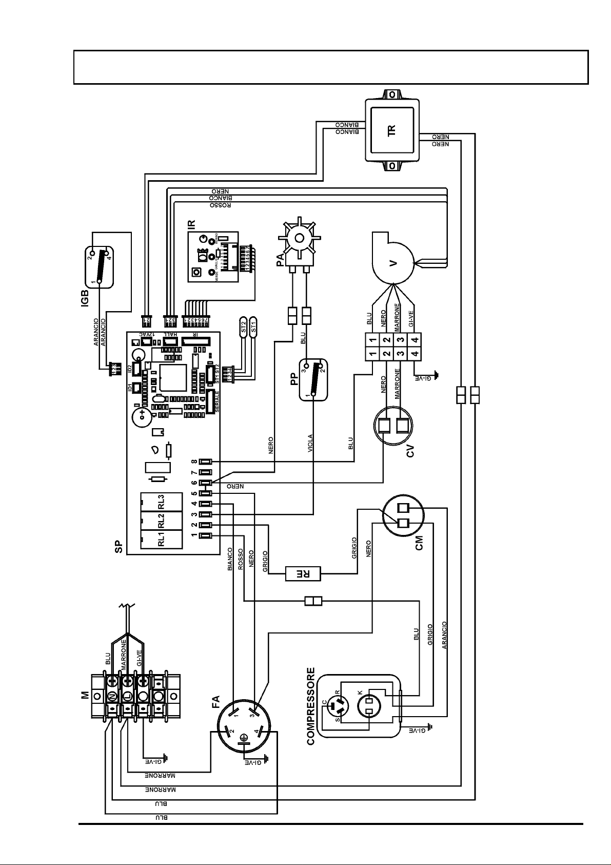
II. SCHEMA ELETTRICO / ELECTRICAL DIAGRAM / SCHALTPLAN
SCHEMA ELECTRIQUE / SCHEMA ELECTRICO
COLORES
Blanco
Azul
Amarillo/Verde
Gris
COULEURES
Blanc
Bleu
Jaune/Vert
Gris
FARBEN
Weiß
Blau
Gelb/Grün
Grau
COLOURS
White
Blue
Yellow/Green
Gray
COLORI
Bianco
Blu
GI-VE
Grigio
Castano
Negro
Rojo
Marrone
Noir
Rouge
Braun
Schwarz
Rot
Brown
Black
Red
Marrone
Nero
Rosso
Verde
Vert
Grün
Green
Verde
3
SCHEDA TECNICA 99024
Page 4
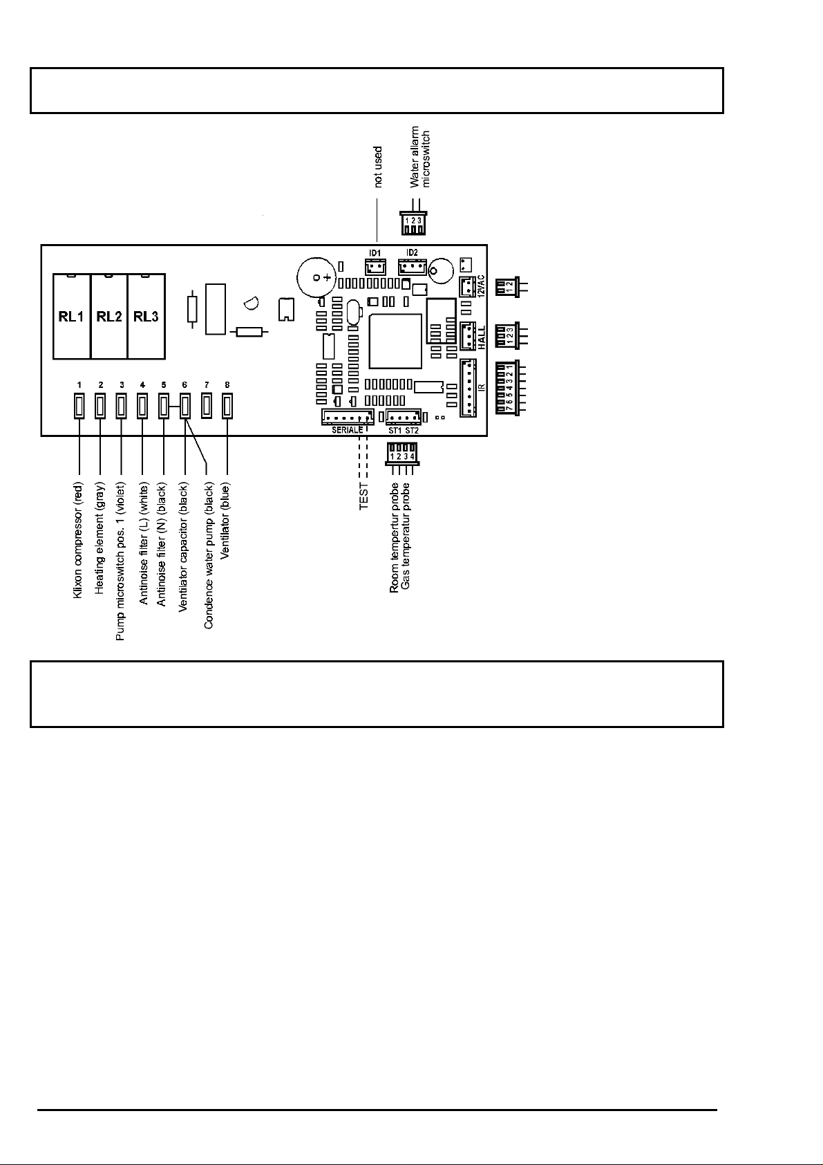
III. SCHEDA DI POTEN ZA / POWER BOARD / HAUPTPLAT INE
CIRCUIT IMPRIMÉ / FICHA DE POTENCIA
Trasformer 12VAC
Ventil ator speed control
Connector to
receiver board
IV. VALORI DELLA SONDA NTC / RESISTANCE OF NTC PROBES
WIDERSTAND DER NTC-SONDEN / VALEURS DE LA SONDE NTC
VALORES DE LA SONDA NTC
Temperatura Resistenza Temperature Resistance Temperatur Widerstand
Température Résistance Temperatura Resistencia
°C
-50 329,2 5 22,0 60 3,0
-45 247,5 10 18,0 65 2,6
-40 188,4 15 14,7 70 2,2
-35 144,0 20 12,1 75 1,9
-30 111,3 25 10,0 80 1,7
-25 86,4 30 8,3 85 1,5
-20 67,7 35 6,9 90 1,3
-15 53,4 40 5,8 95 1,1
-10 42,5 45 4,9 100 0,97
-5 33,9 50 4,2 105 0,86
0 27,3 55 3,5 110 0,76
KΩΩΩΩ °C KΩΩΩΩ °C KΩΩΩΩ
4
SCHEDA TECNICA 99024
Page 5
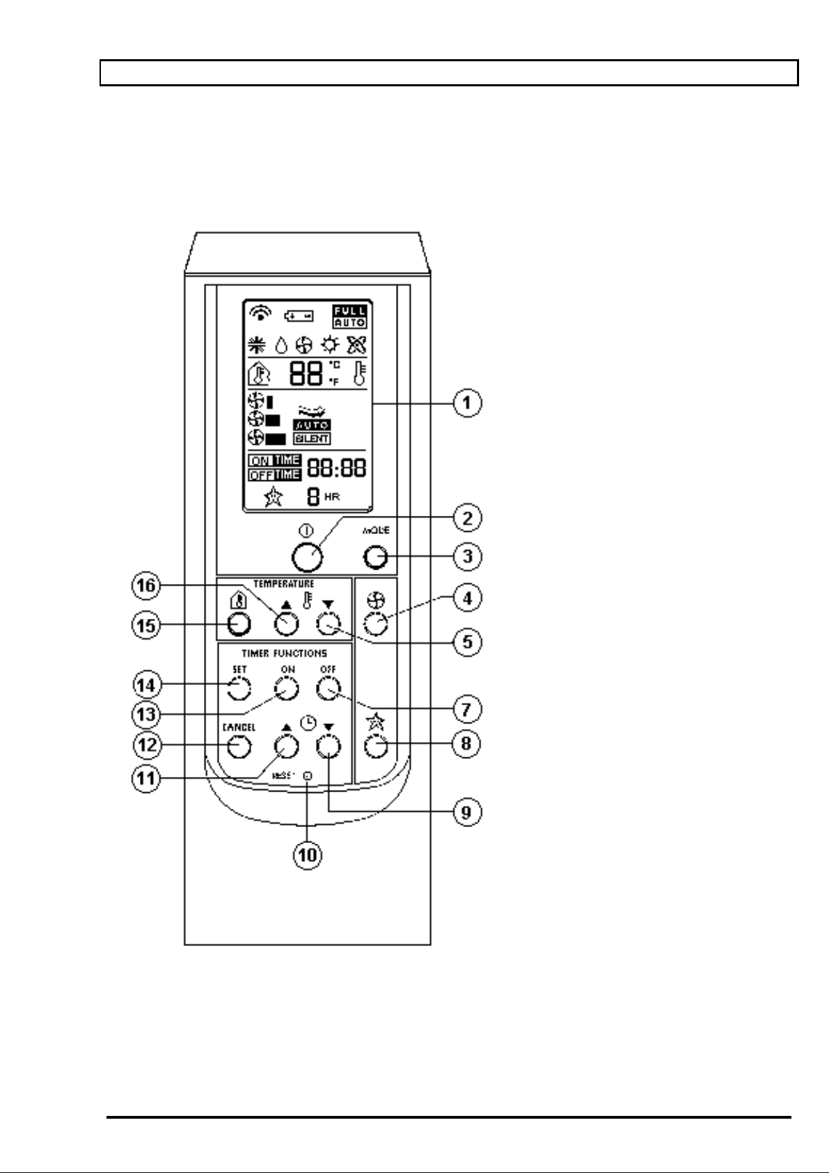
V. THE REMOTE CONTROL
1 DISPLAY
• If the applianc e is in use the func tion
mode is being displayed
• If the applianc e is turned off, only the
clock will remain visible.
2 ON / OFF
• The display lights up when you press
this button.
• Pressing i t again, the display goes out.
3 MODE: FUNCTION SELECTING
• This button selects the various functions:
air-conditioning, dehumidifying,
vent ilation/purification, heating and Full
Auto
4 FAN SPEED
• Determines fan speed: minimum,
medium, maxim um, automatic and
silent
5/16 ROOM THERMOSTAT
• These two buttons select the desired
room temperature.
7/13 ON / OFF: TIMER PROGRAM MI NG
• These buttons program the turning on
and off of the air-condit ioner.
8 SLEEP
•••• This button cont r ols the night-time
operations.
9/11CLOCK AND TIMER PRO-
GRAMMING
•••• These buttons set the hour and minutes
for both the clock and t imer.
12 CANCEL: TIMER
• Cancels the setting on the ON/OFF
timer.
14 SET: CLOCK AND TIMER
VERIFICATION
• Confirms the setting of t he c lock and
the ON/OFF timer.
15 ROOM TEMPERATURE DISPLAY
• Gives you the curr ent room temperature. After about four (4) seconds,
the display will show the temperature
set previously.
10 RESET OF REMOTE CONTROL
•••• Cancels all stored data (time on/off
times) in the remote control.
Afterwards all dis play symbols have to
appear.
5
SCHEDA TECNICA 99024
Page 6

VI. DESCRIPTION OF IMPORTANT APPLIANCE COMPONENTS
A. REMOTE CONTROL
The remot e control is the act ual com mand c enter of the air condi tioner. Thr ough i t you can c hoose all
of the appliance functions along with the desired temperatures and timer settings.
See page 5 for a description of the remote control’s function. (See also
control)
B. LED
The LED‘s of the r eceiver-board indicate the chosen f unc tion of the appliance or any malfunction.
Self diagnostic - remote
RED LED YELLOW LED
OFF OFF OFF
OFF OFF ON
ON OFF ON
OFF ON OFF
ON OFF OFF
** ** **
ON ON ON
OFF BLINKING OFF
BLINKING(2) BLINKING(2) BLINKING(2)
1) The LED’s corresponding t o the automaticall y c hosen appl iance func tion will light up.
2) See also chapter “ S elf-diagnosis”.
3) In order to stop this alarm pr ess the “forced operation button” unt il the doubl e beep signal.
GREEN LED
FUNCTION
OFF
AIR-CONDITIONING
DEHUMIDIFYING
VENTILATION
HEATING
FULL AUTO (1)
TIMER
DIRTY FILTERS
(3)
ALARM (2)
C. FORCED OPE RATION BUTTUN (14)
This button per mits the air condi tioner to func tion without the rem ote control. By means of repeated
pushing of this button all of the functi ons (cooling, dehumi difying, v entilat ion, heating, f ull automat ic,
turn off ) c an be chosen. The appli ance f oll ows the parameters i nstalled i nto the m i croprocessor by the
factor y . See the point
heating and fully automati c functioning.
“Forced function”
of the f unc ti oni ng m odes: cool i ng, dehum i di f yi ng, v ent i lat i on,
D. POWER BOARD
This board is the command and executi ve center of the ai r conditioner. By m eans of the two probes
ST1 (room-temperature probe) and ST2 (gas temperature probe), the IGB (high water alarm
micr oswitch) and t he HALL sensor (v enti lat or speed control) it m onit ors the ambi ent condi tions as well
as the condition of the applianc e. In the case of a def ectiv e probe, HALL sensor or closed contact of
the IGB micr oswitch, the microproc essor puts the appliance into al arm m ode (all 3 LE D’s blink). I f, on
the other hand, t he connection t o other applianc e components should be i nterrupted, this leads to t he
comm and signal being i gnor ed ( breakdown in the connection to receiver board) or to malf unc tion of the
appliance (e,g,: the compressor doesn’t work) but there will be no alarm signal.
On this board is located t he TRIAC which regulates the speed of the vent ilator and the buzz er which
produces an acoustic signal when a comm and is regi stered. The unused “SERIAL” plug, t ogether with
the test board (l isted as special tool n° . 521711), serv e t o carry out t he
the applianc e.
In order to see the arr angement of the electric contacts see page 4.
technicians self diagnosis
of
E. ROOM-TEMPERATURE PROBE (ST1)
The mi croprocessor on the main board determ ines the ambient temperature through this probe. It is
located on the side of the fan.
Importan t: The microp rocessor determin es on the b asis of the t emperature values su ppli ed by
this probe, and not the value from the temperature sensor located in the remote control,
whether th e desired room temperat ure has been reached or n ot. In the aut omatic functio ning
mode it al so decides the speed of t he fan, and in full automati c it chooses the functi on.
6
SCHEDA TECNICA 99024
Page 7

F. GAS PROBE (ST2)
This probe is l ocated on t he aspirat i on tube of t he com pressor where it m easures the gas t em perat ure.
Through this probe t he mi croprocessor determ ines the c orrect f an speed for opti mal f uncti oning of the
appliance.
At a gas temperature lower than -4°C, it tur ns the appliance into the
Through compar ing the temperatur e values from the ST1 and ST2 probes, the microprocessor can
detect a possible
loss of refrigeration gas
which leads to the appliance being t ur ned off .
frost protection mode
.
G. PUMP MICROSWITCH
This microswitch turns on the water pump which pumps the collected condense water over the
condenser radiator where i t evaporates and is blown outside.
H. WATER LEVEL ALARM MICROSWITCH
This microswitch turns the appliance off if the water l evel in the collecting basi n is too high.
I. HALL
This sensor on the power board measures:
a. dur ing the starting period if the ventilator works
b. c ontrols and regulat es the number of turns of the venti lator.
In case of a blockage of the venti lator or a defecti ve HALL sensor the microprocessor will stop the
appliance in alarm mode.
J. VENTILATOR
The v entilat or has four speed lev els which are gov erned by TRI AC: silent , low, medi um and high and
which can be chosen by remot e control. In the “Auto” mode, the m icroprocessor cont rols the speed of
the fan acc ording t o the dif f erence between room -tem perature (as m easured by ST1) and t he desired
room temperature as imposed with the rem ote control.
Function during Alarm
In case of faulty pr obes or gas loss alar m the ventil ator will be turned off .
In case of a “Anti–frost” or a “High-water-alarm” the ventilator will run on low fan speed.
VII. DESCRIPTION OF THE FUNCTIONS
ATTENTION: the stated temperatures can be modified at any time by the manufacturer
A. AIR-CONDITIONING
1. Operational limits
The lowest temperature which can be selected with t he rem ote c ontrol i s 16°C, bel ow the appl i ance wil l
function only as ventil ator. The hi ghest temperatur e setting is 32°C.
Important: The temperature measurement which determines the functioning of the appliance
comes from th e S T1 sensor an d not fro m t he one in t he remote control.
2. Compressor
The compressor starts when the room-temperature is at least 0.8°C higher then the desired roomtemperat ure and there have been passed at least tree m inutes since the l ast turn off of the appliance.
Desired Room-temperature
ON
0,8°C
OFF
Room-temperature (ST1)
3. Fan speed
All f an speeds (sil ent, l ow, medi um , hi gh and „auto“ ) can be m anual l y selec ted wit h t he rem ote cont rol .
In the „auto“ function the fan speed will be selected automatically according to the temperature
difference between the selec ted and actual room-tem per ature according to the diagram next page.
7
SCHEDA TECNICA 99024
Page 8

Auto fan speed
Desired room- temperature
High.
1°C
Med.
1°C
Low.
OFF
0,5°C 1°C Room-temperature (ST1)
4. Forced operation
In the forced-operation the appliance will work only according to the imposed data in the
microprocessor. The imposed desired room-temperature is 24°C, the ventilator will work in auto
function with the desired r oom tem per ature as well being 24°C.
B. .DEHUMIDIFATION
1. Descripti on
For dehumidification the water circulation pump is always turned off and the hot air tube should be
disconnected, so that the applianc e will dehumidi f y wit hout l owering t he room t em peratur e. I n case that
the tube should still be connected, the appl iance will execute a limited cooling operati on, sim il ar to the
existi ng split uni ts like PA C 180. The operati onal li mits are 16 – 32 ° C. Depending on the lower room
temperat ure selected by the remote contr ol we can have ei ther one of t he foll owi ng oper ation modes:
a. If the setting of the desired minimum temperature is more than 4°C below the actual room
temperat ure, then the air conditi oner works as in cooling m ode with constant ly r unning com pressor
and chosen fan speed. With the air outlet connected, this mode will continue until the room
temperat ure has come within 4°C of the desired minimum temperature setting.
b. If t he act ual room tem per ature i s only 4°C or l ess abov e t he desired m i ni m um tem perat ure setti ng,
then the ev aporat or fan switches to the “si lent ” speed l evel. T he com pressor will alternate between
on and off. The operational phase lasts 30 minutes, the off-period 5 minutes.
c. If the actual room temperature corresponds to the desired minimum temperature setting or is
below, then the compressor will remain turned off. The fan works at the “sil ent” speed level.
The diagram shows the dehumidification function with the hot-air-outlet connected. W ith the hot-air
outlet di sconnected, t he room t emperat ure will stay the same and the appliances will not change from
one way of func tioning t o the other.
SET+4°C
SET
Time
Compressor
ON
OFF
chosen fan speed
Silent fan speed
30min
8
5min
SCHEDA TECNICA 99024
Page 9

2. Forced operation
In the forced-operation the appliance will work only according to the imposed data in the
microprocessor. The imposed desired minimum room-temperature is 23°C.
C. VENTILATION
All v entilator speeds can be selected m anually. In automatic f an speed the fan will turn at medium
speed level
D. HEATING
1. Operational limits
The lowest tem peratur e which can be selec ted wit h the r em ote cont rol i s 8°C. The hi ghest tem per ature
setting is 25°C.
Important: The temperature measurement which determines the functioning of the appliance
comes from th e S T1 sensor an d not fro m t he one in the remote con t rol.
Importan t: in order to avoi d co ld air fl o ws, the h ot air o utl et i n th e b ack of t he ap pl ian ce sho ul d
be closed with th e plug su pplied as accessory.
2. Description
The heating element comes in when the room-temperature as measured by ST1 is 0.8°C below the
desired room-temperature. The ventilator will always run at medium speed. Once the desired room -
temperat ure has been reached the heating element t ur ns off, while the ventil ator continuous for anot her
10 seconds. In order to cont r ol well the room temper ature the ventil ator will run for ca. 60 seconds each
20 minut es resting time.
3. Forced operation
In the forced-operation the appliance will work only according to the imposed data in the
microprocessor. The imposed desired room-t emperature is 20°C.
E. FULLY AUTOMATIC FUNCTION
1. Description
The air-conditioner will chose aut omatic ally all operat ing modes acc ording to t he temper ature values
which are programmed in the microprocessor (see following diagram). In t his mode t he therm ostat is
completely out of function.
FUNCTION
COOLING
1°C
1°C
DEHUMIDIFY ING
1°C
1°C
VENTILATION
1°C
1°C
HEATING
20°C 22°C 23°C TEMP E RA TURE
3. Ventilator
The speed of the vent ilat or is determi ned compl etely autom atical ly, whereby t he preset “desired room
temperature” is 23°C (See diagram on page 8). This is the temperature at which the air conditioner
begins cooli ng oper ation.
The diagram on page 8 remai ns valid, whereby 23°C is inserted as the “ desired room temperature”.
4. Forced operation
This func tion corresponds completely to the full automatic mode.
9
SCHEDA TECNICA 99024
Page 10

E. SLEEP FUNCTION
1. Lengt h of operat ion and automatic temp erat ure increase
The air conditioner functions wit h the fan at t he “ si lent” speed level during the set time period.
If during this peri od the desired tem per ature is reached, t hen the appliance t ur ns itself off.
Import ant: Af ter 30 m i nut es of oper ati on, t he appl i ance i ncreases the desired room tem peratur e by 1°C
and again by 1°C after another 30 minutes of operation.
At the end of the set period, the appliance t urns itself off.
Roomtemperature
Air-conditioni ng
1°C
Set
Tim e 1h 2h
Compressor
ON
OFF
1°C
VIII.OPERATIONAL PROBLEMS AND PROTECTIVE FUNCT IONS
1. PROBES, HALL SENSOR AND WATER LEVEL
In the case of unusual probe v alues, m al f unc ti on of t he ventil at or, defecti ve HALL sensor or contact of the
micr oswitch f or the water lev el in the coll ecting basin the air condi tioner shuts itself off and all 3 LED’s
start blinking.
2. GAS LOSS
After 30 minutes of operation the microprocessor compares the temperature values of ST1 and ST2
probes. If t he di f f er ence between the 2 values should be l ess than 2°C f or m or e than 10 m i nutes, then t he
appliance t urns itself off and the 3 LED’s start bli nk ing.
This test is only carried out in the COOLING and DEHUMIDIFYING modes.
3. DIRTY FILTER
After about every 300 hours of operat i on the appl i ance warns that the f i l ter shoul d be cl eaned. T he yel low
LED blinks. The appliance r emains fully operat ional.
In order to tur n the LED off , hold down the em ergency button f or about 6 seconds while the appliance is
functi oning. You hear a double “BEEP BEEP” tone and t he LED turns off.
4. FROST PROTECTION
If the gas temperature in the evaporator sinks below -4 °C (24.8°F), then the frost protection is
automatically activated. The compressor is being turned off. The fan is switched to low speed. The
compressor will be only turned on again when the gas temperature has reached 0°C (32°F).
H. SELF-DIAGNISTIC
1. User‘s diagnostic
With the appl iance in alarm, press the forced operati on button for about 4 seconds until the beep si gnal:
green LED
off off off
off off
off
off
on
on on on
on on
(In the case of various problems, only one problem will be shown by the LED‘s.)
yellow LED red LED
on
on
on on
off
off
on
off
Problem
No problem
Room-temperature probe (ST1)
Gas-temperature probe (ST2)
Gas loss
High wat er alarm
Ventilator
Pressure switch (not connected)
10
SCHEDA TECNICA 99024
Page 11

2. TECHNICIAN‘S DIAGNOSTIC
a. Activation
Pull t he power plug and insert the test boar d code n°. 521711 in t he S E RIAL connection of the main board.
Put the power plug back into the socket.
If t he appliance should t ur n on, turn it off.
Bridge the TEST points of the main board by pressing once the test button of the test board until the
double beep signal.
The technic ian’s diagnosis is now activated and i s i n the fi r st test phase.
b. Descript ion of diagnosis
1. Immediately af ter the double beep t he appliance is in the first phase of the self diagnosti c .
green LED
on on off
blinking
on
blinking blinking
Press the forced oper ation button in order to get into the second phase of the test program
green LED
blinking blinking off
on
blinking
on on
yellow LED red LED
on off
blinking
yellow LED red LED
blinking off
on
off
off
off
off
Problem
No problem
Defective Roo m- t emperature probe (ST1)
Defective Gas temperature probe (S T2)
Both probes defective
Problem
No problem
High pressure alarm (not connected)
High wat er alarm)
Pressure and water alarm (no pressure switch
connected
3. In the third phase all outputs of the main board are checked one by one. Each pressing of the
emergency button means another step in the diagnosis.
1st pressing - minimum speed int er nal fan
2nd pressing -medium speed internal fan
3rd pressing - maximum speed i nternal fan
4th pressing - - - - - 5th pressing - - - - - 6th pressing - com pr essor on
3. REMOTE CONT ROL
Press the “RESET” button or remove the batteries from the remote control so that the display is entirely
turned off. For ar ound 2 seconds all operational symbols will appear on the remote control display.
Important: All data stored in the remote control (for ex. time and on/off program) will be canceled.
11
SCHEDA TECNICA 99024
Page 12

V. IL TELECOMANDO
1 DISPLAY FUNZIONI
• Se acceso viene visualiz z ato il modo di
funzi onamento
• Se spento v iene v isualizzato solamente
l’orologio.
2 TASTO ACCENSIONE /
SPEGNIMENTO
• Premendo il tasto si acc ende il displ ay ;
• Ripremendo il di spl ay si spegne.
3 TASTO SELEZIONE FUNZIONE
• Premendo il tasto si selezionano i vari
modi di funzionamento:
Condizionamento, deumidificazione,
Ventil azione, ri scaldamento, full auto.
4 TASTO SELEZIONE VELO CITA’
VENTILATORE
• Premendo il t asto si sel ez ionano le
velocità del vent ilatore: minima, media
Massima, aut o , silent.
5/16 TASTI TERMOSTATO AMBIENTE
• Per selezionare la temperatura
desiderata nell’ambiente .
7/13 TASTI PROGRAMMAZ ION E
TIMER
• Per programmarlo spegni mento e
l’accensione del condizionatore.
8 TASTO SLEEP
•••• Per impostar e la funzione notte.
9/11TASTI PROGRAMMAZIONE
OROLOGIO TIMER
•••• Per regolare ora e minuti dell’orologio e
del timer.
12 TASTO CANCELLAZIONE TIMER
• Per annullare la programmazi one
dell’orologio o del t imer O N/OFF.
14 TASTO CONFERMA OROLOGIO
O TIMER
• Per annullare la programmazi one
dell’orologio o del t imer O N/OFF.
15 TASTO VISUALIZZAZIONE
TEMPERATURA AMBIENTE
• Premendo il tasto si visual izza la
temperat ura dell’ambiente (dopo 4
secondi circ a torna alla visual izzazione
precedente).
10 RESET
6
SCHEDA TECNICA 99024
Page 13

VI. DESCRIZIONE DEI COMPONENTI PRINCIPALI
A. L E D
I led di c ontrollo indicano i l funzionamento scel to o event uali guasti .
LED ROSSO LED GIALLO
LED VERDE F UNZIONE
SPENTO SPENTO SPENTO SPENTO
SPENTO SPENTO ACCESO CONDIZIONAMENTO
ACCESO SPENTO ACCESO DEUMIDIFICAZIONE
SPENTO ACCESO SPENTO VENTILAZIONE
ACCESO SPENTO SPENTO RISCALDAMENTO
** ** ** FULL AUTO
(1)
ACCESO ACCESO ACCESO TIMER
SPENTO LAMPEGGIA SPENTO FILTRI SPORCHI
(3)
LAMPEGGIA LAMPEGGIA LAMPEGGIA ALLARME (2)
1) * Sono accesi i LE D c he c or r ispondono alla funzione automaticamente scelta.
2) Vedi anche paragr afo” autodi agnosi ” .
3) Per spegnere la spia, resettare la macchina prem endo il pulsante i l funzi onamento manual e fino a
quando si sentirà un beep seguit o da un doppio beep.
B. TASTO DI FUNZIONAMENTO FORZATO
Questo tasto consente i l funzionamento del climatizz atore anche senza il telecomando.
Premendo ri pet utam ent e il t asto, t utt e le funzioni (c ondiz ionamento – deum idi f i caz i one – v ent i laz ione full auto) possono essere selezionate in sequenza senza la possibilità di variare i parametri già
impostat i nel m icroprocessore.
C. SCHEDA DI POTENZA
Questa è la scheda di comando del climatizzatore. Con le due sonde ST1 (sonda ambiente) e
ST2(sonda aspirazione), i microint erruttore IGB (mic rointerruttore gal leggiante bacinel la) e il sensore
vel ocità vent ola (HALL) essa controlla l’ambiente circostante, nonché l a condizione dell’apparecchio
stesso. Con un errore di sonda, HALL o il cont atto chiuso del microinterrutt or e IGB, il m icroprocessore
Attiva l ’appar ec c hio in allarme (t utti e tr e i LED lampeggi ano) .Se manca invece il collegamento ad altri
Componenti dell’apparecchio, questo porta ad ignorare il segnale di comando ( er rore nel collegamento
Alla scheda di ricevimento / pulsante di emergenza) oppur e ad una funzione errata dell’appar ec c hio
(p. es. il compressore non funz iona) non viene segnalato dal lampeggio led.
Su questa scheda si trovano anche il TRIAC che regola la veloc ità del venti latore, i relè per pom pa,
nonché il buzzer che emette un segnale acustico al ricevimento di un comando. L’entrata libera
“SERIALE” serve, i n c ollegam ento alla scheda test, disponibile come accessorio, all’aut odiagnosi
dell’apparec c hio .
Per i collegament i dei contatti elettrici, vedere lo schema elettri c o pag.4.
SONDA DI TEMPERATURA (ST 1)
Attraverso questa sonda il microproc essore sull a scheda pr incipale r ileva la temperatura ambiente.
Importante: Il microprocessore decide, in base al valore della temperatura rilevato da questa
sonda e non secondo il valore della sonda temperatura ambiente che si trova nel telecomando.
D. SONDA DI EVAPORAZIONE (ST2)
Questa sonda si trova sul tubo di aspi r azione del compressore, dov e misura la temperatura del gas.
Con una temperat ura del gas al di sott o di –4
Attraverso un confronto di temperatura delle due sonde ST1 e ST2 il microprocessore rivela
un’eventuale perdita di refrigerante che porta allo spegnimento dell’apparecchio nella modalità
d’allarme.
0
C essa commuta l’apparecchio nella funzione antigelo.
E. MICROINTERRUTTORE POMPA
Questo mi crointerruttore avvia la pom pa dell’acqua per port are l’acqua sulla batteria condensante.
7
SCHEDA TECNICA 99024
Page 14

F. MICROINTERRUTTORE ALARME LIVELLO D’ACQUA
Questo mi crointerruttore spegne l’apparecchio quando la baci nella di rac c olta è pieno.
G. HA LL
Con questo sensore il microprocessore sulla scheda principale r ileva :
a) se il v entilator e dell’apparecchio in fase d’avviamento funziona ;
b) controlla e r egola i gir i del motore.
In caso di non funzionamento o irregolare velocità del ventilatore il microprocessore spegnerà
l’apparecchio in modalità al larme.
H. VENTILATORE
Il ventilatore ha quattro livelli di velocità che vengono regolat i attrav erso il TRIAC: silent – minimo –
medio - massi mo e che possono essere scelti manualm ent e con i l t el ecom ando. Nel l a f unz ione “ Auto”
il microprocessore comanda la velocità di questo ventilatore secondo la differenza di temperatura
ambient e, misurat a dalla ST1, e la tem per atura ambi ente desiderata dall’util izzatore.
VII. DESCRIZIONE DEL FUNZIONAMENTO
ATTENZ IO NE : LE TEM PERAT URE INDI CATE NE I VARI G RFI CI, POS SONO VARIARE DA MODELLO
A MODE LLO.
A. CONDIZIONAMENTO
1. Limiti di funzionamento
La temperatura più bassa selezionabil e è di 16
funzi ona soltanto nel modo “v entilazione”. La temperatura am biente più alta selezionabile è di 35
Importante: La misurazione della temperatura ambiente determinante per la funzione del
climatizz atore è quella della sonda ST1 e non della sonda del telec omando.
0
C.Al di sotto di questa temperatura il climatizzatore
0
C.
2. Compressore
Il compr essore si accende se la tem peratura am bient e supera quella i mpostat a da alm eno 0,8
0
C e se
sono passati almeno 3 minuti dall’ultimo spegnimento .
Temperat ura impostat a
ON
0,8°C
OFF
Temperat ura ambient e ( S T1)
3. Ventilatore
Il ventilatore ha quattro livelli di velocità che vengono regolat i attrav erso TRIAC : silent – minimo –
medio – massimo e che possono essere scelti manualmente con il tel ec omando.
Nella funzione “Auto” il microprocessore comanda la velocità di questo ventilatore secondo la
differenza di temperatura tra la temperatura ambiente, misurata dal la ST1, e l a temperatur a ambiente
desiderata dall’util izzatore.
Velocità ventilatore in automatico
Temperat ura ambient e impostata
High.
1°C
Med.
Low.
OFF
1°C
0,5°C 1°C Temperatura ambi ente (ST1)
8
SCHEDA TECNICA 99024
Page 15

4. Funzionamento forzato
L’apparecchio f unziona solo secondo i dati memori zzati nel m icroprocessore. La tem peratura m inima
per il condi zionament o è di 24
temperat ura ambient e desi der ata essendo 24
0
C. Il v entilat ore dell’evaporat ore lavora i n funzione autom atica con la
0
C.
B. FUNZIONE DEUMIDIFICAZIONE
1. Descrizio ne del funzionamen t o
La funzione deum idif icazione è un condiz ionamento li mitat o con veloc ità ridott a del vent ilatore e con
l’inserimento / spegnim ento periodico del com pressore. La tem peratura più bassa selezionabile è di
0
C.
16
a. La temperatura impostata è inferiore di oltre 4
Il climatizzatore funziona nel modo condizionamento con funzionamento costante del
compressore. Il ventilatore funziona nella velocità scelta. Questa funzione continua finché la
temperat ura ambient e ar r iv a a 4
0
C dalla temperatura minima im postata.
b. S e la tem peratur a ambi ente ef f etti v a è 4
si Commut a nel liv ello di v eloc ità “Si lent”. I l compr essore si accende e si spegne periodicam ente.
La fase di accensione è di 30 min. il per iodo di spegnim ento è di 5 minuti.
c. Se la tem peratura ambiente eff ettiv a corri sponde all a temperatura im postata o se è più bassa, il
compressore rimane spento. Il ventilatore funziona.
SET+4°C
0
C rispetto alla tem per atura ambi ente esistente:
0
C o meno sopra la t emperatura i mpostata, i l v entil atore,
SET
Time
Compressore
ON
5min
OFF
30min
velocità sel ezionata
Velocità silent
2. Funzionamento forzato (con tasto SW1)
L’apparecchio funziona secondo i dati memorizzati nel microprocessore. La temperatura ambiente
minima prestabilita è di 23
0
C e non può essere vari ata.
C. FUNZIONE VENTI LAZIONE
La velocità del vent ilatore può essere impostata m anualmente o aut omatic amente.
In funzione automatica il ventilator e funziona a veloc ità auto che cor r isponde alla velocità media.
D. FUNZIONE RISCALDAMENTO
1. Limiti di funzionamento
La temperat ura può essere impostata manualmente da 8
0
C fino a 250C.
Importante: in questa funzione l’usci ta scaric o aria deve essere chiusa con l’apposi to t appo accessorio
per evitare l’uscita d’aria dal retro dell’apparecchio e per garantire il flusso d’aria necessario per
raffreddare la resi stenz a.
2. Descrizione
Il riscaldamento si accende se la temperatura misurata dalla sonda ST1 è più bassa di quella
impostat a di alm eno 0,8
0
C. Il ventilatore funziona al la media veloc ità.
Quando raggiunge la temperatura impostata il riscaldamento si spegne ma il ventilatore funziona
ancora per 10 secondi.
Il contr ollo della temper atura avviene ogni 20 mi nuti fac endo funzionar e il ventilatore per 1 m inuto.
9
SCHEDA TECNICA 99024
Page 16

3. Funzionamento forzato.
L’apparecchio funziona solo secondo i dati impostati nel micropr oc essore. La temperatura im postata è
0
C.
di 20
E. FUNZIONE FULL AUTO
1. Modi di funzi onamento
Il climatizzatore sceglie automat ic am ente tutti i modi di f unz ionamento secondi i valori di tem per atura
che sono impostati fissi nel microprocessore. Vedi diagramma che segue. In questa funzione il
termostat o è c ompletamente inatt iv o.
FUNZIONE
CONDIZIONAMENTO
1°C
1°C
DEUMIDIFICAZIONE
1°C
1°C
VENTILAZIONE
1°C
1°C
RISCALDAMENT O
20°C 22°C 23°C TEMP E RA TURA
3. Velocità del ventilatore
In condizionamento viene det er minata automati camente anche la velocità in funzi one della differ enz a
Di tem peratura fr a la temper atura ambiente e la temperatura programmata in auto che è di 23
0
C.
In riscal damento il ventilator e funziona sempre sulla velocità medi a.
4. Funzionamento forzato
Corrisponde al funzionamento full auto senza l’uso del telecom ando.
E. FUNZIONE SLEEP
Il cl imatizzatore funziona per il tempo indicat o in fase di impostaz ione con il ventilatore evaporat or e sul
liv el lo di v eloci tà “auto”. Se durante i l f unzi onamento si dov esse raggiungere l a tem peratur a am biente
desiderata, l’apparecchio si spegne. Importante: L’apparecchio aument a dopo 30min.di funzionamento
La temperatura ambiente desiderata di 1
trascorso il tempo impostato , l ’appar ec c hio si spegne.
Temperatura ambiente S T1
Condizionamento
Set
1°C
0
C e dopo ulteriori 30 min. di un altro grado. Una volta
1°C
Timer 1h 2h
Compressore
ON
OFF
10
SCHEDA TECNICA 99024
Page 17

VIII.PROBLEMI DI FUNZIONAME NTO E FU NZIONI DI PROTEZIONE
1. SONDE, HALL, E LIVELLO DELL’ACQUA.
in caso di valori anomali delle sonde, mal funzionamento del v entilatore o sensore ventilatore nonché
l’intervento del microinteruttore per il livello dell’acqua nella bacinella di raccolta, il climatizzatore si
spegne da solo e tutti e tre i LED lampeggiano.
2. PERDITA GAS
Dopo 30 min. di funzionamento il microprocessore effettua un confronto di temperat ur a delle sonde ST1 e
ST2. Se l a differenza di t emperatura t r a queste sonde dovesse scendere durante il funzionamento per più
di 10 minuti al di sotto di 2
Questo test viene effett uato soltanto nei modi di funzionamento CONDIZ IONAMENTO e
DEUMIDIFICAZIONE.
3. FILTRI SPO RCHI
Ogni 300 ore di funzionamento l’apparecchio vi ricorda di pulire i filtri. Il LED giallo lampeggia e
l’apparecchio funzi ona. Per spegnere il LE D tenete premut o il tasto di funzionamento forzato nel panello di
comando per circa 6 secondi, sentirete un doppio “beep” ed il led si spegne. Per eseguire questa
operazione non si deve spegnere l’apparecc hio.
0
C, l’apparecc hio si spegne e i tre LED lampeggiano.
4. FUNZIONE ANTIGELO
Se la temperatur a del gas nell’ev aporatore dov esse scendere al di sott o –4
la funz ione antigelo. Il compressore si spegne. Il ventilatore commuta passando alla velocità minima.
Il compressore si accende soltanto quando la temperatura del gas è salit a a 0
0
C, si atti va aut omati camente
0
C.
H. AUTODIAGNOSI
1. Diagnosi utente
Azionate il tasto di funzionamento forzato per circa 4 secondi finché sentirete un beep. Dopo aver
rilasciato il tasto i LED indicano l’anom alia come segue :
LED VERDE
off off off
off off
off
off
on
on on on Ventilatore
on on
2. DIGNOSI RISERVATA AL TECNICO
a. ATTIVAZIONE
Toglier e la spina dalla presa ed i nserite la scheda di test a codice 521711 nel connettore SE RIAL della
scheda principale. Inserit e la spina nell a pr esa.
Se l’apparecchio inizia a funzionare spegnetelo.
Caval ottate i punt i TEST dell a scheda principal e premendo una vol ta il tasto della scheda di test f inché
sentirete un doppio beep.
La diagnosi tecnica è atti vata e si trova nella pri ma fase di test.
LED GIALLO LED ROSSO PROBLEMA
Nessuno
on Sonda ambiente
on
off
Sonda evaporatore (ST2)
on on Perdita gas
off
on Bacinella di racco lta acqua pi ena
off
Pressostato
(ST1)
b. Diagnosi tecnica
1. Immediatamente dopo il doppio segnal e beep l’apparecchio si trova nella fase di autodiagnosi.
LED verde
acceso ac c eso spento
lampeggia
acceso
lampeggia lampeggia
LED giallo LED rosso Problema
Nessuno
acceso spento
lampeggia
spento
spento
Sonda ambiente (ST1) difettosa
Sonda dell’evaporatore (ST2) difettosa
Tutte due sonde difettose
11
SCHEDA TECNICA 99024
Page 18

Premete ora il tasto di funzionamento forzato nel pannello di c omando per passare alla seconda fase.
LED verde
lampeggia lampeggia spento
acceso
lampeggia
acceso acceso
3. Nella t erza f ase vengono cont roll ati man m ano tutt e le usci te del la scheda pri ncipal e. O gni successiv o
azionamento del tasto di funzionamento f or z ato significa un avanzament o della diagnosi.
1 A z ionamento - ventilatore velocità min.
2 A z ionamento - ventilatore velocità med.
3 A z ionamento - ventilatore velocità max.
4 ----------------5 ----------------6 A z ionamento - c ompressore acceso
3. TELECOMANDO
Azionare il tasto “RESET” o togliere le batterie dal telecomando finché tutte le visualizzazione siano
spente ; per cir c a 2 secondi vengono visual izzati tutti i simboli di comando sul display del telecomando.
Importante: Tutti i dati memorizzati nel telecomando vengono cancellati.
LED giallo LED rosso Problema
Nessuno
lampeggia spento
acceso
spento
spento
Allarme pressione (nessun p ressostato col legato)
Allarme acqua(nessun gall eggiante collegato )
Allarme pressione ed acqua (non collegate)
12
SCHEDA TECNICA 99024
 Loading...