

Page 1
INTRODUCTION
Thank you for choosing this De’Longhi product. Please take a few
minutes to read these instructions. This will prevent running any
risks or damaging the appliance.
Symbols used in these instructions
Important warnings are identied using the symbols listed
below. It is absolutely necessary to pay close attention to these
warnings.
Failure to follow the indications given could lead to electrical
shocks, serious injury, burns, re or damage to the appliance.
Danger!
Failure to comply could lead to injury from electrical shock and
risk of death.
Attention!
Failure to comply could lead to injury or damage to the appliance.
Please note:
This symbol highlights advice and important information for the
user.
Problems and repairs
For any repairs, always consult the Technical Service Centres
authorised by the manufacturing company. Always request
original replacement parts. Repairs performed by unqualied
personnel can be dangerous and void the warranty.
WARNINGS
Essential safety requirements
Only use the room air conditioner according to the instructions
in this manual. These instructions do not cover every possible
condition and situation that could occur. Common sense and
prudence must always be followed during installation, operation and storage of any electrical appliance. This appliance was
built for household use and must not be used for other purposes.
Attention!
• This appliance can be used by children
aged from 8 years and above and persons with reduced physical, sensory or
mental capabilities or lack of experience
and knowledge if they have been given
supervision or instruction concerning
use of the appliance in a safe way and
understand the hazards involved. Children shall not play with the appliance.
Cleaning and user maintenance shall not
be made by children without supervision.
• Do not set heavy or hot objects on the appliance.
Danger! Since the appliance uses electricity, the follow-
ing safety instructions must be followed:
• Modifying or changing the characteristics of the appliance
in any way is dangerous.
• The appliance must be installed according to national laws
governing electrical systems.
• For any repairs, always consult the Technical Ser vice Centres authorised by the manufacturing company. Repairs
performed by incompetent individuals can be hazardous.
• This appliance must be earthed. Have the electrical system
checked by a qualied electrician.
• Avoid using extension cords.
• Before any cleaning or maintenance operation, always un-
plug from the mains.
• Do not pull on the electrical cord to move the appliance.
• Do not install the appliance in areas where the air may con-
tain gas, oil or sulphur or near heat sources.
• If the power cable is damaged, it must
be replaced by the manufacturer or the
manufacturer’s Customer Services in order to avoid all risk.
Please note:
• Clean the air lter at least once a week.
• When transporting, the appliance must be kept upright or
resting on one side. Before transporting, drain all the water
from the appliance. After transporting, wait at least one
hour before turning on the appliance.
• Do not cover the appliance with plastic bags when stored.
• The packaging materials are recyclable. Please place them
in the appropriate recycling collection containers.
• At the end of its life, deliver the air conditioner to the appropriate collection centres.
6
Page 2
Check the plate for the type of refrigerant gas used
in your appliance.
WARRANTY AND TECHNICAL ASSISTANCE
Warranty and technical assistance conditions are indicated in the
documentation provided with your appliance.
Specic information regarding appliances with
R410A refrigerant gas
R410 is a refrigerant gas that complies with EC ecology regulations. Do not puncture the refrigerant circuit on the appliance.
Environmental information: This unit contains uorinated
greenhouse gases covered by the Kyoto Protocol. Maintenance
and disposal must only be performed by qualied personnel
(R410A, GWP=2088).
Specic information regarding appliances with
R290 refrigerant gas
• Thoroughly read all of the warnings.
• When defrosting and cleaning the appliance, do not
use any tools other than those recommended by the
manufacturing company.
• The appliance must be placed in an area without any
continuous sources of ignition (for example: open ames,
gas or electrical appliances in operation).
• Do not puncture and do not burn.
• Refrigerant gases can be odourless.
• The appliance must be installed, used and stored in an area
that is greater than 15 m2.
• This appliance contains 300 g of R290 refrigerant gas.
• R290 is a refrigerant gas that complies with the European
directives on the environment. Do not puncture any part of
the refrigerant circuit.
• If the appliance is installed, operated or stored in a non-
ventilated area, the room must be designed to prevent the
accumulation of refrigerant leaks resulting in a risk of re
or explosion due to ignition of the refrigerant caused by
electric heaters, stoves, or other sources of ignition.
• The appliance must be stored in such a way as to prevent
mechanical failure.
• Individuals who operate or work on the refrigerant
circuit must have the appropriate certication issued by
an accredited organisation that ensures competence in
handling refrigerants according to a specic evaluation
recognized by associations in the industry.
• Repairs must be performed based on the recommendations
from the manufacturing company.
Maintenance and repairs that require the assistance of
other qualied personnel must be performed under
the supervision of an individual specied in the use of
ammable refrigerants.
TECHNICAL DATA
Power supply See characteristic plate
Max absorbed power
in air conditioning “
Refrigerant “
Cooling capacity “
Limit operating conditions:
Temperature in the room
being cooled 21 ÷ 35°C
Disposal of the appliance
The appliance must not be disposed of with household
waste but taken to an authorised waste separation and
recycling centre.
Electrical Connection
Before plugging into the mains, check the following:
• the mains voltage is the same as that indicated on the plate
on the back of the appliance;
• the socket and electrical line are sized to support the load
required;
• the socket is the proper type for the plug, otherwise, replace the socket;
• the socket is connected to an ecient earthing system. The
manufacturer is not responsible in the event of non-compliance with these injury prevention standards.
• The power cable must only be replaced by specialised technicians.
7
Page 3
Below you will nd all the information necessary for operating
134
your air conditioner.
The appliance must be placed where there are no obstacles to
air intake and output.
DESCRIPTION
Description of the appliance (See page 3 - A)
A1 Air outlet grille
A2 Control panel
A3 Handles
A4 Wheels
A5 Filter
A6 Air intake grille
A7 Air exhaust hose housing
A8 Air intake grille
A9 Power supply cable
A10 Drainage hose with 2 caps
A11 Remote control signal receiver
Description of accessories (See page 3 - B)
B1 Wall ange with cap
B2 Air exhaust hose
B3 Hose adapter (2 pieces)
B4 Wall mounting accessory
B5 Crosspiece grille
B6 Cap for crosspiece hole
B7 Crosspiece
B8 Screws
B9 Window outlet
B10 Remote control
• Lower the window (g. 4).
• Set the air conditioner near the window. Insert the air
exhaust hose B2 previously assembled in the grille on the
crosspiece B7 (g. 5). Make sure the air exhaust hose is not
obstructed.
• When not using the appliance, the crosspiece hole can be
covered with the cap B6 provided.
Double casement window
• Apply the window outlet B9 to the air exhaust hose B2 that
was previously assembled, as shown in g. 6.
• Open the window or French door slightly and set the outlet
B9 in place as shown in gure 7.
Limit the length and curves of the air hose as much as
possible, avoiding any obstruction.
AIR CONDITIONING WITH INSTALLATION
If desired, your appliance can also be installed semi-permanently following the distances shown in the gure 8.
In this case, the following steps are necessary:
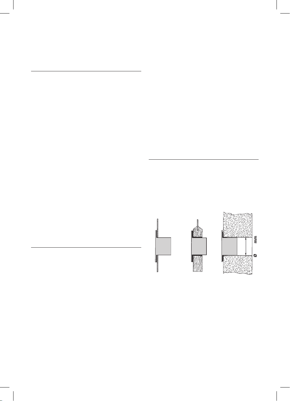
• Drill a hole (134 mm diam.) in an outside wall or through
the glass in a window. Follow the height (see g. 9) and
sizes of the hole indicated in gure below.
AIR CONDITIONING WITHOUT INSTALLATION
Just a few simple steps and your air conditioner will ensure your
comfort:
• Screw a hose adapter B3 to one end of the air exhaust hose
B2.
• Fit the other adapter B3 in the air exhaust hose housing A7
on the back of the appliance (see g. 1).
• Screw the end of the hose without an adaptor to the adaptor previously attached to the appliance (see g. 1).
Sash window
• Fit the crosspiece grille B5 to the crosspiece B7 and attach
it using the 4 screws provided B8 (g. 2).
• Open the window.
• Put the crosspiece B7 in the window, extending it the en-
tire width of the window (g. 3).
• Once the crosspiece has been extended, it can be attached
by screwing in the remaining two screws provided.
in the window
glass
Limit the length and curves of the air hose as much as
possible, avoiding any obstruction.
in the wood
base of the
French door
in the wall: we
recommend
insulating the
section of the wall
with a suitable
insulation material
8
Page 4

• Attach the ange accessory B1 provided to the hole.
• Fit the adapter B3 in the air exhaust hose housing A7 on
the back of the appliance (see g. 1).
• Screw the wall mounting accessory B4 on the air exhaust
hose B2. If necessary, remove the other adapter B3 from
the air exhaust hose B2 by unscrewing it (g. 10).
• Screw the hose on the machine.
• Fit the end of the hose B2 to the ange B1 as shown in g.
9.
Whenever the hose B2 is not attached, the hole can be
closed using the cap for the ange B1.
NOTE: for semi-permanent installations, we recommend leav-
ing a door slightly open (even just 1 cm) to ensure the proper
air exchange.
CONTROL PANEL page. 4 C
CONTROL PANEL DESCRIPTIONS
C1 ON/STAND-BY (on/o ) key
C2 Function selection key MODE (air conditioner,
dehumidier, fan)
C3 Temperature increase key
C4 Temperature decrease key
C5 Fan speed selection key (MIN/MED/MAX/AUTO)
C6 REAL FEEL status indicator
C7 Air conditioner symbol
C8 Dehumidier symbol
C9 Fan symbol
C10 Timer symbol
C11 Alarm symbol
C12 Swing symbol
C13 SILENT symbol
C14 Set temperature values, programmed on/o time
C15 Fan speed indicator
C16 Timer indicator
C17 Selected temperature scale indicato
CONTROL PANEL OPERATION
TURNING THE APPLIANCE ON AND OFF (g. 11)
Insert the plug in the socket. Two dashes appear on the display
indicating that the appliance is in stand-by
Touch the (C1) key to turn on the appliance.
Il ap A1 will open after few seconds.
When the appliance comes on, the last function set before it was
shut o is activated.
NOTE: If start-up is not continued, after a few minutes the
display light dims in order to reduce energy consumption.
To turn the appliance o, touch the , key and then pull the
plug.
NOTE: Never turn o the air conditioner by simply pulling the
plug. Touch the key in order to put your air conditioner in
stand-by and wait a few minutes before pulling the plug. In this
manner, the appliance can perform the operating status checks.
AIR CONDITIONER MODE (g. 12)
This is ideal for hot and humid weather when the room needs to
be both cooled and dehumidied.
To correctly set this mode:
• Touch the MODE key until the air conditioning symbol ap-
pears. The display will show the desired temperature.
• To change the temperature to be reached, touch the + (C3)
key or the - (C4) key.
• Select the desired fan speed by touching the key.
The speeds available are:
Minimum speed: when maximum silent operation is
desired.
Medium speed: when the noise level needs to be
low but with a good comfort level.
Maximum speed: to reach the desired tempera-
ture as soon as possible.
The appliance automatically chooses the best
fan speed based on the temperature selected and the environmental conditions.
The most suitable temperatures during the summer range from 24
to 27°C. However, setting the temperature signicantly lower than
the outdoor temperature is not recommended.
DEHUMIDIFIER MODE (g. 13)
This is ideal for reducing humidity in the room (spring and au-
tumn, damp rooms, rainy periods, etc.)For this type of use, the
appliance must be set up as for air conditioner mode. That is, the
air exhaust hose (B2) must be tted to the appliance to allow the
humidity to be discharged outside.
To correctly set this mode:
• Touch the MODE key until the dehumidier symbol appears.
9
Page 5

FAN MODE (g. 14)
When using this mode, the air exhaust hose (B2) does not need
to be attached to the appliance.
To correctly set this mode:
• Touch the MODE, key until the fan symbol appears.
• Select the desired fan speed by touching the key. .
The speeds available are:
Minimum speed: when maximum silent operation is
desired.
Medium speed: when the noise level needs to be
low but with a good fan level.
Maximum speed: for maximum fan power.
SELECT THE TEMPERATURE SCALE g. 15)
The temperature can be displayed in °C or °F.
To change the temperature unit of measure keep depressed
both keys “+” e “-” for about 10 sec.
FUNCTIONS AVAILABLE FROM THE REMOTE CONTROL
ONLY
(See page 4 - D)
FUNCTION g. 16)
REAL FEEL is a De’Longhi technology that checks the relative humidity and regulates the temperature at the same time. These
are the two most important elements for comfort.
Compare to traditional air conditioning, REAL FEEL maintains
comfort conditions over time, automatically modulating the
compressor and fan speed.
To activate the function, touch the key.
The “REAL FEEL” status indicator (C6) becomes white for approx.
1 min. to indicate that the appliance is checking the room conditions.
After a while the “REAL FEEL” status indicator (C6) changes col-
our as it approaches comfort conditions (see graph below).
ORANGE LIGHT:Environmental conditions
dier signicantly from comfort conditions
GREEN LIGHT: Environmental conditions
satisfactory for most people, almost perfect.
BLUE LIGHT: Perfect environmental
conditions
Perfect!
10
Please note:
• Comfort is subjective. Consequently, dierent individuals
can judge the same environmental conditions dierently.
• In particularly severe environmental conditions (large
room size, high outdoor temperature or humidity, little
room insulation, many people or large thermal loads in the
room, exposure to the sun, etc.), the appliance may not be
able to reach comfort conditions.
SILENT FUNCTION CAN ONLY BE ACTIVATED IN AIR
CONDITIONER MODE g. 17)
By activating this function in air conditioner mode, the noise
level of the appliance is further reduced.
To activate, touch the (D6) key.
The display shows the related indicator light (C13).
PROGRAMMING THE TIMER g. 18)
The timer allows for the delayed start up or shut down of the
appliance. This function will prevent wasting electricity by optimising the operating periods.
How to program delayed start up
• Plug in the appliance and set to standby.
• Touch the timer key (D8): the timer symbol (C10) and hours
light up.
• Use the + (D2.2) or - (D2.1) key to set the number of hours
until the appliance should start up.
• The appliance will start to operate in the same operating
mode that was previously set.
Start up can be programmed at any time within the 24 hours
that follow. A few seconds after the timer is set, the setting is
acquired. The timer symbol stays lit and the display returns to
standby.
To cancel the timer program, touch the timer key (D8). twice.The
timer symbol (C10) will go o.
How to program delayed shut down
• While the appliance is on in any operating mode, delayed
shut down can be programmed.
• Touch the timer key (D8): The timer symbol (C10) and hours
light up.
• Use the + (D2.2) o - (D2.1) key to set the number of
hours until the appliance should shut down.
A few seconds after the timer is set, the setting is acquired, the
display shows the operating mode and the timer symbol stays
lit.
Once the set time is elapsed, the air conditioner goes into Standby.
To cancel the timer program, touch the timer key (D8), twice.
The timer symbol (C10) will go o.
Page 6

OPERATION USING THE REMOTE CONTROL
(See page 4 - D)
• Aim the remote control at the receiver (A11) on the air
conditioner. The maximum distance between the remote
control and the appliance is 5 metres (with no obstacles
between the remote and the receiver) g. 19.
• The remote control should be handled with extreme care,
without dropping it or exposing it to direct sunlight and
keeping it away from heat sources.
DESCRIPTION OF THE REMOTE CONTROL
D1) “ON/STAND-BY” button
D2.1)Temperature decrease / programmed operation button
D2.2)Temperature increase / programmed operation button
D3) “MODE” function button
D4) Fan speed selection button ( )
D5) REAL FEEL selection button
D6) SILENT selection button
D7) SWING button (ap swing)
D8) TIMER button
SWING BUTTON
The SWING button (D7) moves the grille ap, evenly distri-
buting the air into the room.
When the SWING button is pressed, the ap will begin to
move forwards and backwards alternatively.
If pressed again, the ap will be locked into its current po-
sition.
When the button is next pressed, the ap will start to move
forwards and backwards again.
NOTE: in order to avoid damaging the internal mechanisms, the
ap must not be moved manually.
INSERTING OR REPLACING BATTERIES
• Remove the cover on the back of the remote
• Insert two LR03 “AAA” 1.5 V batteries in the proper position
(see the indications inside the battery compartment).If the
batteries are low, replace them with the same type.
• Replace the cover.
TURNING THE APPLIANCE ON AND OFF
• Insert the plug in the socket.
• Press the (D1) button on the remote control (when the
air conditioner is turned on, the last function set before it
was shut down will start).
• To turn the appliance o, press the (D1) button on the
remote control then pull the plug.
NOTE: Never turn o the air conditioner by only pulling the plug.
Press the key and wait a few minutes before pulling
the plug. In this manner, the appliance can perform the
operating status checks.
SELECTING THE OPERATING MODES
The commands available on the remote control correspond to
those on the appliance control panel (C).
Therefore, refer to the instructions in the previous chapters.
NOTE: The special functions D5-D6-D7-D8, are available from
the remote control only.
TIPS
There are some recommendations to follow to achieve maximum air conditioner performance:
• close the windows and doors in the room to be cooled
(g. 20). The only exception is in the event of installation
through a hole in the wall.In this case, it is recommended
to leave a small opening through a door or window in order
to ensure the proper air exchange (g. 20).
• Non utilizzare l’apparecchio in ambienti ad alto tasso di
umidità (tipo lavanderia).
• Do not use the appliance in areas with a high degree of hu-
midity (laundries for example).
• Protect the room from direct sunlight by pulling the drapes
and/or partially closing the shutters for extremely economic operation (g. 21).
• Do not use the appliance outdoors.
• Make sure there are no heat sources in the room.
• Make sure the air conditioner is level on the oor.
• Do not place objects on the air conditioner (g. 22);
• Do not obstruct the air intakes.
When replacing or disposing of the remote control, the
batteries must be removed and disposed of according to
current legislation as they are damaging to the environment.Do not mix alkaline batteries, standard (zinc-carbon) batteries or rechargeable (nickel cadmium) batteries.Do not throw the batteries in the re as they could
explode or release hazardous liquids.
CLEANING
Before every cleaning or maintenance operation, shut down the
appliance using the ke y.
Then pull the plug.
11
Page 7

CLEANING THE APPLIANCE
We suggest cleaning the appliance with a damp cloth and then
drying it.For safety reasons, do not wash the air conditioner with
water.
Precautions
Do not use gasoline, alcohol or solvents for cleaning.Do not spray
liquid insecticides or similar substances.
CLEANING THE AIR FILTER OR SILVER-ION AIR FILTER
(only on some models)
To maintain the eciency of the air conditioner, it is recommended to clean the dust lter after every week of use.
The lter is located near the intake grille. Remove the grille to
access the lter. To clean the lter, it will need to be extracted as
shown in g. 23-24.
Use a vacuum cleaner to remove any dust deposited on the lter.
If it is very dirty, submerge it into warm water and rinse it several
times. The water temperature must be kept below 40° C.
After washing the lter, allow it to dry.
To replace, put the lter back in its housing.
If present, the silver-ion air filter not only retains powder particles, but also performs an efficient antibacterial action. In addition, it greatly reduces irritants such as pollen and spores.
The filter is treated with small particles of silver (with dimen-
sions equal to millionths of a millimetre) which are able to
block the multiplication of bacteria and spores when in contact
with them, and therefore encourage their destruction.
CHECKS AT THE START OF THE SEASON
Make sure the power cable and socket are in perfect condition
and make sure the earthing system is ecient.Comply stric tly
with the installation standards.
END OF SEASON OPERATIONS
To completely drain the water from the internal circuit, remove
the cap from the outside of the drainage hose, turning it counter
clockwise. Then remove the internal cap (g. 25).
Drain the water completely into a basin.When it is completely
drained, replace the caps, making sure they are completely
closed.
Clean the lter as indicated previously. The lter must be completely dry before reinserting it.
Transporting, loading, cleaning, recovery and disposal of
the refrigerant must only be performed by technical service centres authorised by the manufacturing company.
The appliance must only be disposed of by specialised
personnel authorised by the manufacturing company.
12
Page 8

SELFDIAGNOSIS
The appliance has a self-diagnosis system that identies some operating errors.
The error messages appear on the appliance display.
IF THE FOLLOWING APPEARS ON
THE DISPLAY...
“Low Temperature”
... DO THE FOLLOWING
The appliance has a defrosting device
that prevents excessive ice build ups.The
appliance automatically starts operating
again once the defrosting process is complete.
IF THE FOLLOWING APPEARS ON
THE DISPLAY...
“High Level”
... DO THE FOLLOWING
Empty the inner safety tray by following
the instructions in the paragraph “END OF
SEASON OPERATIONS”.
If the error occurs again, consult the nearest authorised service centre.
IF THE FOLLOWING APPEARS ON
THE DISPLAY...
“Probe Failure”
Failure 1
Failure 2
... DO THE FOLLOWING
If this appears, consult the nearest authorised service centre.
13
Page 9

TROUBLESHOOTING
Check the following points before calling the authorised Technical Service Centre in your area.
PROBLEMS CAUSES SOLUTIONS
The air conditioner does not turn on lt is not plugged in plug it in
there is no power wait
The air conditioner works for a short
period of time
The air conditioner runs but does not
cool the room
During operation there is an unpleasant
odour in the room
The air conditioner does not work for
about 3 minutes from restart
The display shows the symbol with
one of the following messages:
HL/PF/FI/F2
the internal protection device was
triggere
the air exhaust hose is obstructed or
bent
an obstruction is impeding air exhaust
outside
windows, doors, drapes open close the windows, doors and drapes,
there is some heat source in the room
(oven, hair dryer, etc.)
the air exhaust hose is disconnected
from the appliance
dust lters clogged clean or replace the lters as previously
the technical characteristics of the
appliance are not suitable for cooling the
room where it is located
dust lters clogged clean or replace the lters as previously
to protect the compressor there is an
internal device that delays startup for
about 3 minutes from restart
the appliance has a self-diagnosis
system that identies some operating
errors
call the help centre
correctly position the air exhaust
hose, limiting the length and curves
as much as possible and avoiding any
obstructions
identify and remove the obstacles that
impede air exhaust outside
keeping in mind the “recommendations
for proper use”
eliminate the heat source
attach the air exhaust hose to the
housing on the back of the appliance
(g.1)
described
described
wait; this time delay from restart is
normal
refer to the SELF-DIAGNOSIS chapter
14
 Loading...