

DeLonghi DFG 903 User Operating Instructions Manual
DFG 903
Professional cooker
Before operating this cooker,
please read these instructions carefully
Users Operating Instructions
GB

2
Dear Customer
Thank you for choosing one of our appliances which has been carefully designed and
built by our specialist staff and thoroughly tested to satisfy your cooking requirement.
We suggest that you read this Instruction Booklet so that you will understand fully how
to operate the appliances.
Please keep the booklet handy. You may wish to refer to it at a later date.
De Longhi

3
Contents
Model DFG 903
Page Number
Introduction . . . . . . . . . . . . . . . . . . . . . . . . . . . . . . . . . . . . . . . . . . . . . . . . . . . . . 4
Assembling the backguard . . . . . . . . . . . . . . . . . . . . . . . . . . . . . . . . . . . . . . . . . 4
Features and technical data . . . . . . . . . . . . . . . . . . . . . . . . . . . . . . . . . . . . . . . . . 5
Control panel . . . . . . . . . . . . . . . . . . . . . . . . . . . . . . . . . . . . . . . . . . . . . . . . . . . . 6
Minute counter . . . . . . . . . . . . . . . . . . . . . . . . . . . . . . . . . . . . . . . . . . . . . . . . . . . 7
How to use the hob burners . . . . . . . . . . . . . . . . . . . . . . . . . . . . . . . . . . . . . . . . 8
How to use the gas oven . . . . . . . . . . . . . . . . . . . . . . . . . . . . . . . . . . . . . . . . . . .11
How to use the grill . . . . . . . . . . . . . . . . . . . . . . . . . . . . . . . . . . . . . . . . . . . . . . .13
Oven light . . . . . . . . . . . . . . . . . . . . . . . . . . . . . . . . . . . . . . . . . . . . . . . . . . . . . . .14
Important notes . . . . . . . . . . . . . . . . . . . . . . . . . . . . . . . . . . . . . . . . . . . . . . . . . .15
After sales service . . . . . . . . . . . . . . . . . . . . . . . . . . . . . . . . . . . . . . . . . . . . . . . . .15
Do’s and do not’s . . . . . . . . . . . . . . . . . . . . . . . . . . . . . . . . . . . . . . . . . . . . . . . . .16
Care and maintenance . . . . . . . . . . . . . . . . . . . . . . . . . . . . . . . . . . . . . . . . . . . . .17
For the installer
Location . . . . . . . . . . . . . . . . . . . . . . . . . . . . . . . . . . . . . . . . . . . . . . . . . . . . . . . 22
Fitting the adjustable feet . . . . . . . . . . . . . . . . . . . . . . . . . . . . . . . . . . . . . . . . . . .23
Stability bracket . . . . . . . . . . . . . . . . . . . . . . . . . . . . . . . . . . . . . . . . . . . . . . . . . .24
Provision for ventilation . . . . . . . . . . . . . . . . . . . . . . . . . . . . . . . . . . . . . . . . . . . .25
Gas installation . . . . . . . . . . . . . . . . . . . . . . . . . . . . . . . . . . . . . . . . . . . . . . . . . . .26
Conversion to LPG . . . . . . . . . . . . . . . . . . . . . . . . . . . . . . . . . . . . . . . . . . . . . . . .28
Lubrication of the gas taps . . . . . . . . . . . . . . . . . . . . . . . . . . . . . . . . . . . . . . . . . .33
Electrical installation . . . . . . . . . . . . . . . . . . . . . . . . . . . . . . . . . . . . . . . . . . . . . . .34
4
Introduction
Congratulations on your purchase of this Delonghi gas cooker which has been carefully
designed and produced to give you many years of satisfactory use.
Before using this appliance it is essential that the following instructions are carefully read and
fully understood.
We would emphasise that the installation section must be fully complied with for your safety
to ensure that you obtain the maximum benefits from your appliance.
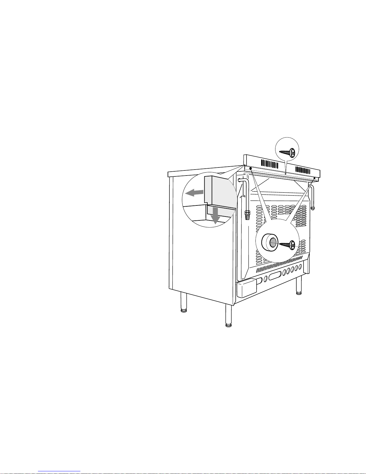
Fig. 1
This cooker has been designed, constructed and marketed in compliance with:
- safety requirements of EEC Directive “Gas” 90/396;
- safety requirements of EEC Directive “Low voltage” 73/23;
- protection requirements of EEC Directive “EMC” 89/336;
- requirements of EEC Directive 93/68.
A
B
Backguard
Before installing the cooker, assemble the backguard “C” (fig. 1).
Please note that :
• The backguard “C” can be found
packed at the rear of the cooker.
• Before assembling remove any
protective film/adhesive tape.
• Remove the two spacers “A” and
the screw “B” from the rear of the
cooktop.
• Assemble the backguard as
shown in figure 1 and fix it by
screwing the central screw “B”
and the spacers “A”.
This appliance is designed and manufactured solely for the cooking of domestic
(household) food and in not suitable for any none domestic application and therefore
should not be used in a commercial environmement.
The appliance guarantee will be void if the appliance is used within a none domestic
environnement i.e. a semi commercial, commercial or communal environment.
5
Features and technical data
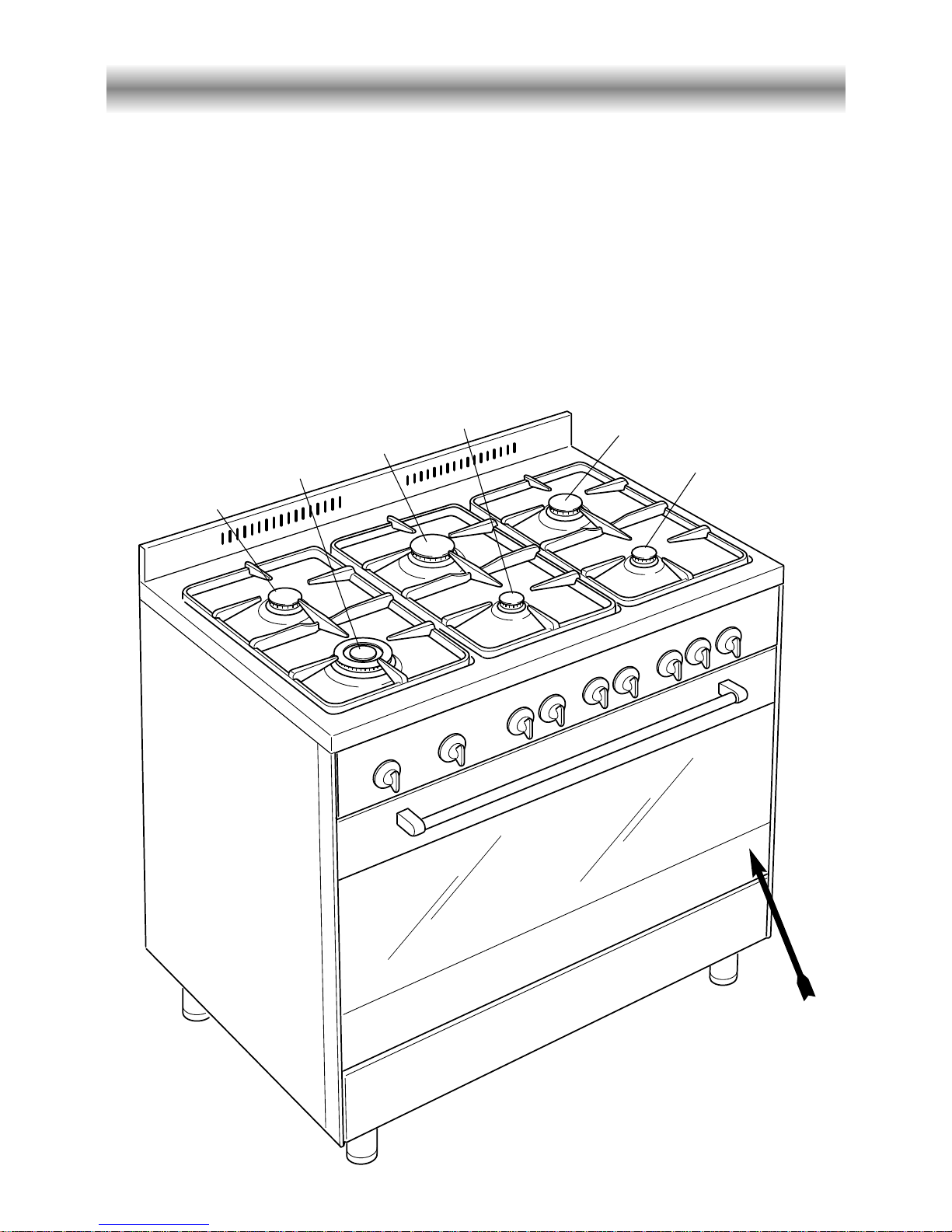
Fig. 2
2
1
3
4
6
5
Identification label
When you open the oven
door the indentification label
is at the bottom right hand
side.
Gas burners
1. Triple-ring burner (TC) 3,50 kW
2. Semi-rapid burner (SR) 1,75 kW
3. Rapid burner (R) 3,00 kW
4. Auxiliary burner (A) 1,00 kW
5. Semi-rapid burner (SR) 1,75 kW
6. Auxiliary burner (A) 1,00 kW
Gas oven
– Oven burner 6,20 kW
– Grill burner 4,65 kW
– Oven lamp 15 W
– Usable oven volume 99,5 dm
3
6
Control panel
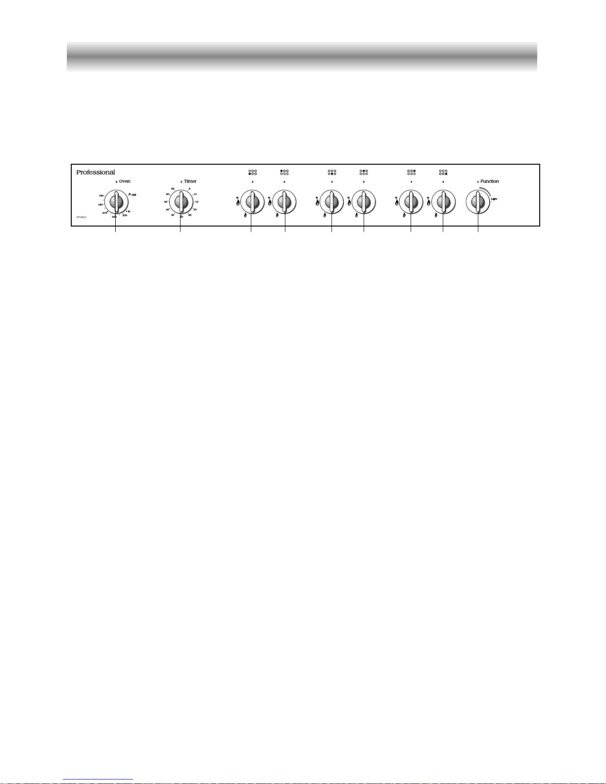
Fig. 3
1 2 34 56 789
CONTROL PANEL - Controls description
1. Gas oven / gas grill control knob
2. Minute counter
3. Front left burner control knob
4. Rear left burner control knob
5. Front central burner control knob
6. Rear central burner control knob
7. Rear right burner control knob
8. Front right burner control knob
9. Oven light control knob
7
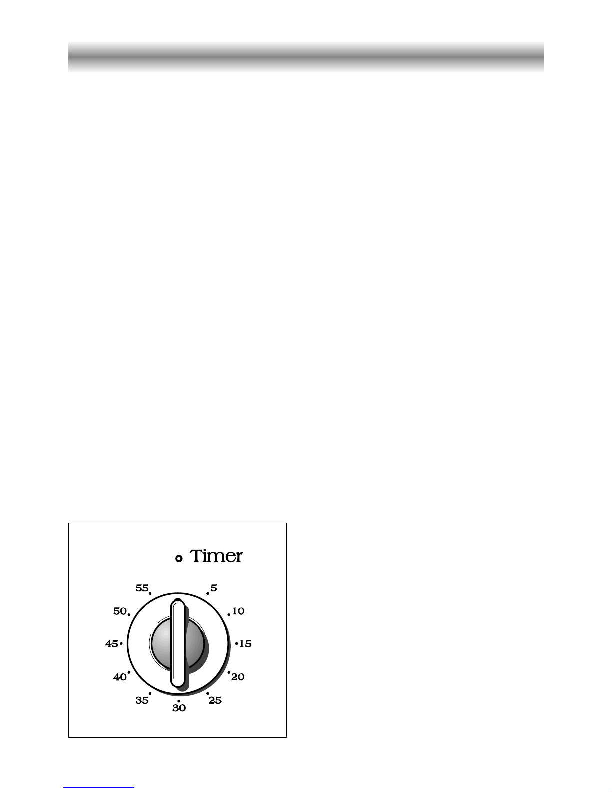
Minute counter
Minute counter
The minute counter is a timed acoustic
warning device which can be set for a
maximum of 60 minutes.
The knob (Fig. 4) must be rotated
clockwise as far as the 60 minute
position and then set to the required
time by rotating it anticlockwise.
Fig. 4
8
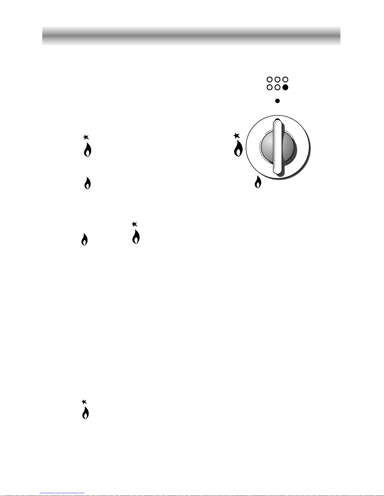
How to use the hob burners
Hob burners
Each hob burner is controlled by a
separate gas tap operated by a control
knob (fig. 5) which has 3 positions marked
on the control panel, these are:
– Symbol ● : tap closed (burner off)
– Symbol : High (maximum)
– Symbol : Low (minimum)
Push in and turn the knob anti-clockwise
to the selected position.
Lighting of the hob burners
To ignite the burner, the following instructions are to be followed:
1) Lightly press and turn the knob anti-clockwise, and position the knob indicator to the
symbol printed on the control panel (fig. 5).
2) Press the knob to operate the electric ignition; or, in the case of a mains failure light the
burner with a match or lighted taper.
3) Adjust the burner according to the setting required.
Low High
To turn the burner off, fully rotate the knob clockwise to the off position: ●.
The maximum setting of the control tap is for boiling, the minimum setting is for slow
cooking and simmering.
All working positions must be choosen between the maximum and minimum setting, never
between the maximum setting and the “OFF” position.
Fig. 5
Electric ignition
The sparks generated by the electrodes close to the burners will ignite the choosen
burner. Whenever the lighting of the burners is difficult due to peculiar conditions of
the gas features or supply, it is advised to repeat the ignition with the knob on
“minimum” position.
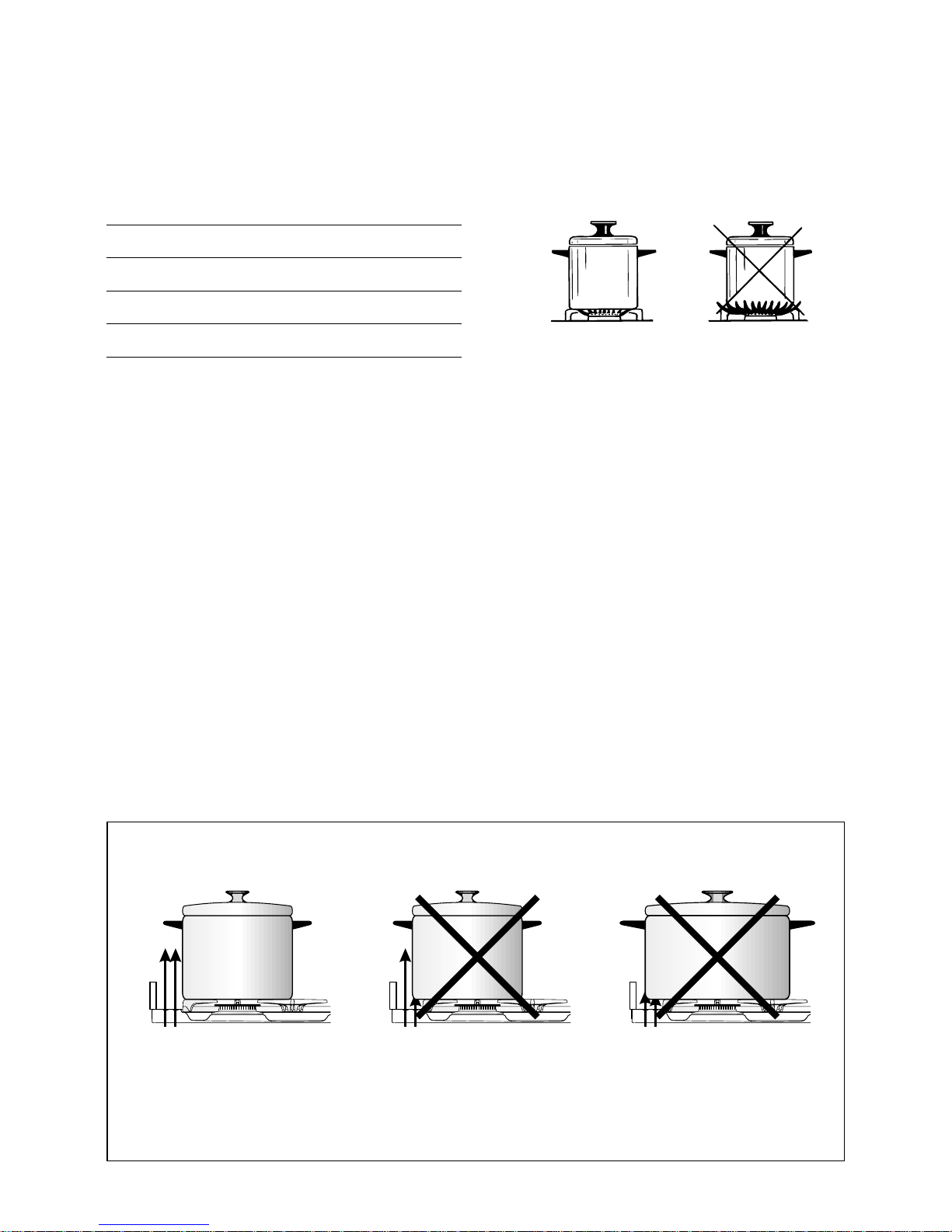
Burners Pan diameter
Auxiliary 12 ÷ 14 cm
Semi-rapid 16 ÷ 24 cm
Rapid 24 ÷ 24 cm
Triple-ring 26 ÷ 28 cm
do not use pans with concave or convex bases
9
Fig. 6a
Choice of burner
The burner must be choosen according to the diameter of the pans and energy required.
Saucepans with handles which are excessively heavy, in relationship to the weight of the
pan, are safer as they are less likely to tip.
Pans which are positioned centrally on burners are more stable than those which are offset.
It is far safer to position the pan handles in such a way that they cannot be accidentally
knocked.
When deep fat frying fill the pan only one third full of oil.
DO NOT cover the pan with a lid and DO NOT leave the pan unattended.
In the unfortunate event of a fire, leave the pan where it is and turn off all controls.
Place a damp cloth or correct fitting lid over the pan to smother the flames.
DO NOT use water on the fire.
Leave the pan to cool for at least 30 minutes.
AIR FLOW
(cooling fan)
AIR FLOW
(cooling fan)
AIR FLOW
(cooling fan)
CORRECT USE OF RAPID BURNER
Fig. 6b
10
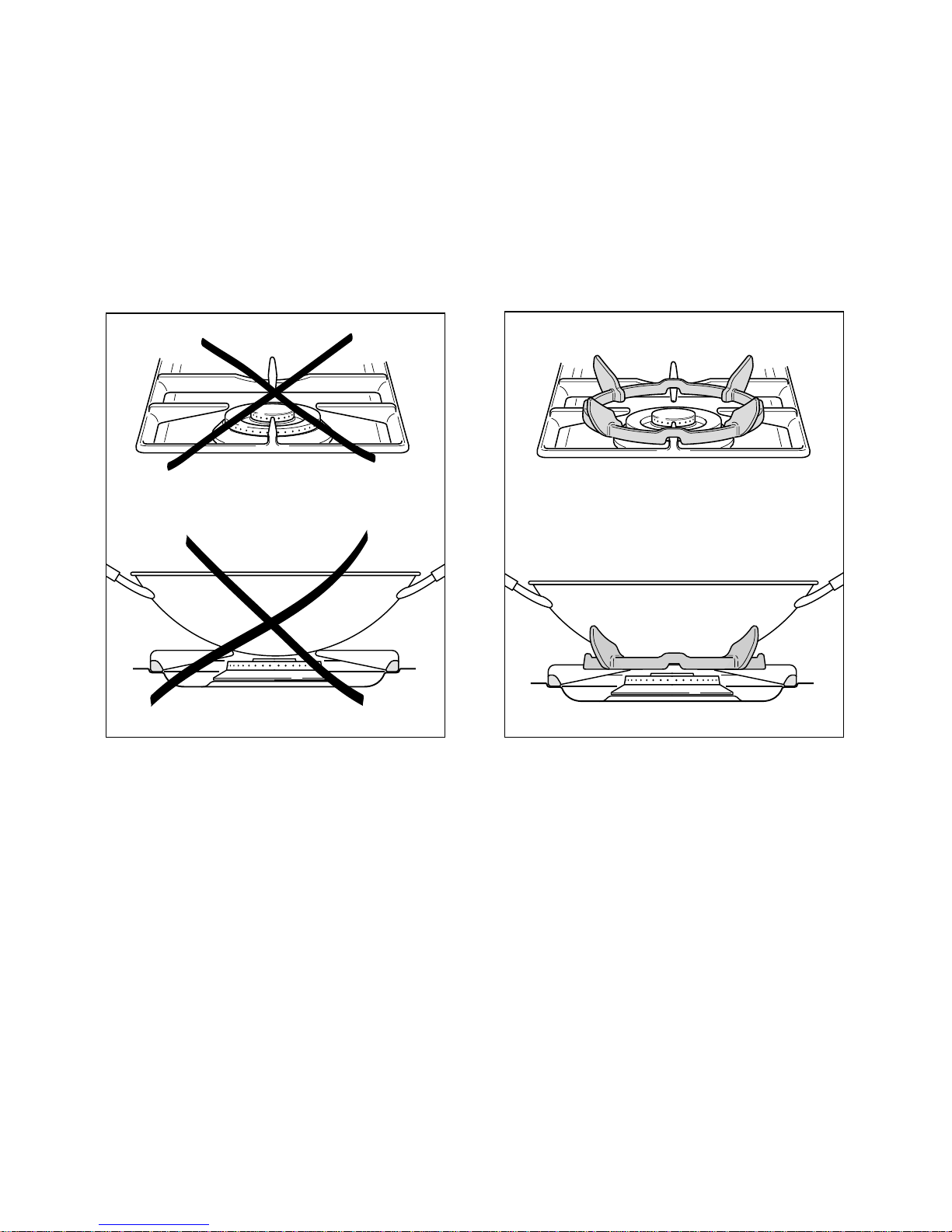
Correct use of the triple-ring burner
The flat-bottomed pans are to be placed directly onto the pan-support.
To use the WOK you need to place the proper stand in order to avoid any faulty
operation of the triple-ring burner (Fig. 7a - 7b).
Fig. 7a
WRONG
Fig. 7b
CORRECT
11
How to use the gas oven
Lighting the oven gas burner
The thermostat allows the automatic control of the temperature.
The gas delivery to the oven burner is controlled by a two way thermostatic tap (oven
and grill burners) with flame-failure device.
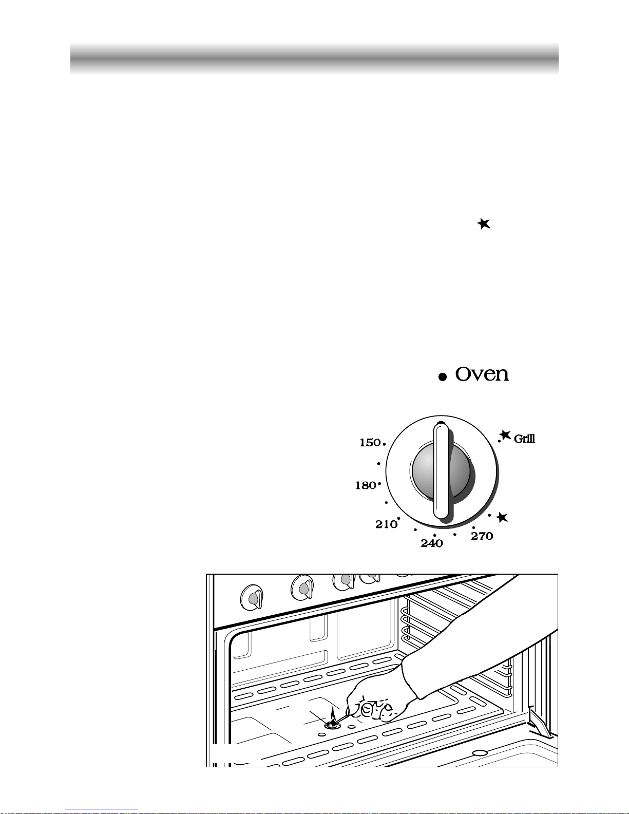
To light the oven burner operate as follow:
1) Open the oven door
2) Lightly press and turn the thermostat knob anti-clockwise to max position “ ”.
3) Press the knob right down to prime the electric ignition.
WARNING: Risk of explosion!
The oven door must be open during this operation.
In case of power cut, press the knob and immediately approach a lighted match to the
opening “A” (fig. 8). Never continue this operation for more than 15 seconds. If the
burner has still not ignited, wait for about 1 minute prior to repeating the ignition.
4) Wait about 10/15 seconds after the burner lighting before releasing the knob (time of priming
of the valve).
5) Close the oven door slowly and adjust the burner
according to the power required.
Should the flame of the burner estinguish
for any reason, the safety valve will cut off
automatically the gas flow to the tap.
To re-start operation, take the knob to “off”
position, wait for at least 1 minute and
repeat operations as above explained.
Oven thermostat
The oven thermostat (fig. 9) is marked with
numbers, these correspond to the oven
temperature, in addition the “OFF” position is
shown by the
symbol ●.
To choose the
required oven
temperature (check
with the “Oven
cooking
temperatures”), turn
the control knob until
its line mark is level
with the number
required on the
control panel (facia).
Fig. 8
A
Fig. 9
 Loading...