

Page 1

Dell Wyse ThinOS Release 8.3.2
Administrator’s Guide
Page 2

Notes, cautions, and warnings
NOTE: A NOTE indicates important information that helps you make better use of your product.
CAUTION: A CAUTION indicates either potential damage to hardware or loss of data and tells you how to avoid the
problem.
WARNING: A WARNING indicates a potential for property damage, personal injury, or death.
Copyright © 2017 Dell Inc. or its subsidiaries. All rights reserved. Dell, EMC, and other trademarks are trademarks of Dell Inc. or its
subsidiaries. Other trademarks may be trademarks of their respective owners.
2017 - 01
Rev. A04
Page 3

Contents
1 Introduction.....................................................................................................................6
About this Guide.................................................................................................................................................................6
Technical Support.........................................................................................................................................................6
Release scope.....................................................................................................................................................................7
2 Getting Started: Quickly Learning the Basics.................................................................. 8
Connecting to a Remote Server......................................................................................................................................... 8
Connecting a Remote Server Manually.........................................................................................................................9
Using Your Desktop............................................................................................................................................................ 9
Conguring Thin Client Settings and Connection Settings................................................................................................10
Connecting to a Printer.....................................................................................................................................................10
Connecting to a Monitor...................................................................................................................................................10
Locking the Thin Client..................................................................................................................................................... 10
Signing O and Shutting Down.........................................................................................................................................10
Additional Getting Started Details...................................................................................................................................... 11
Zero Desktop Features.................................................................................................................................................11
Zero Interactive Desktop Guidelines.............................................................................................................................11
Zero Toolbar................................................................................................................................................................ 12
List of Connections.....................................................................................................................................................12
Classic Desktop Features..................................................................................................................................................13
Classic Interactive Desktop Guidelines........................................................................................................................ 13
Using the Shortcut Menu............................................................................................................................................13
Using the Desktop Menu.............................................................................................................................................14
Using the Connection Manager...................................................................................................................................14
Login Dialog Box Features.................................................................................................................................................15
Accessing System Information.......................................................................................................................................... 16
3 Global Connection Settings........................................................................................... 19
4 Conguring the Connectivity.........................................................................................21
Conguring the Network Settings.....................................................................................................................................21
Conguring the General Settings................................................................................................................................ 21
Conguring the DHCP Options Settings.................................................................................................................... 23
Conguring the ENET Settings.................................................................................................................................. 24
Conguring the WLAN Settings................................................................................................................................. 26
Conguring the Proxy Settings...................................................................................................................................28
Conguring the Remote Connections.............................................................................................................................. 29
Conguring the Broker Setup.....................................................................................................................................30
Conguring the Visual Settings.................................................................................................................................. 38
Conguring the General Options................................................................................................................................40
Conguring the Authentication settings.....................................................................................................................40
Conguring the Central Congurations............................................................................................................................ 60
3
Page 4

Conguring the General Central Congurations ......................................................................................................... 61
Conguring the WDA Settings....................................................................................................................................61
Conguring the VPN Manager.........................................................................................................................................65
5 Conguring Thin Client Settings................................................................................... 69
Local Settings Menu.........................................................................................................................................................69
Conguring the System Preferences..........................................................................................................................69
Conguring the Display Settings.................................................................................................................................72
Conguring the Peripherals Settings...........................................................................................................................77
Conguring the Printer Settings.................................................................................................................................85
Reset Features.................................................................................................................................................................94
Resetting to Factory Defaults Using G-Key Reset......................................................................................................95
Resetting to Factory Defaults Using Shutdown Reset................................................................................................95
Resetting Display Settings Using V-Key Reset............................................................................................................95
Accessing Thin Client BIOS Settings..........................................................................................................................95
6 Citrix HDX RealTime Multimedia Engine (RTME)..........................................................96
Introduction......................................................................................................................................................................96
Installing RTME package on ThinOS.................................................................................................................................96
Setting up the RealTime Multimedia Engine (RTME) connector.......................................................................................97
Verifying the RTME 1.8 Status..........................................................................................................................................99
Verifying the RTME 2.1 Status........................................................................................................................................ 100
7 Advanced Details on Conguring ICA and RDP Connections........................................102
Conguring ICA Connections..........................................................................................................................................102
Conguring RDP Connections........................................................................................................................................ 106
8 ICA SuperCodec........................................................................................................... 111
ICA 14.0.0.91.....................................................................................................................................................................114
9 Features of RDP 8.1...................................................................................................... 116
Verifying the Status of VOR/H.264 ................................................................................................................................116
Work Flow of Dual Display................................................................................................................................................117
Support Matrix for RDP 8.1.............................................................................................................................................. 118
10 Introduction to Flash Redirection................................................................................ 119
Flash Redirection.............................................................................................................................................................119
11 Introduction to TCX 7.0 Flash Redirection................................................................... 123
Working Status of TCX 7.0 Flash Redirection.................................................................................................................. 123
12 Performing Diagnostics.............................................................................................. 125
System Tools...................................................................................................................................................................125
Using the Trouble Shooting Options................................................................................................................................132
A Central Conguration: Automating Updates and Congurations..................................138
How to Set Up Automatic Updates and Congurations.................................................................................................. 138
Using DHCP Options................................................................................................................................................ 138
4
Page 5

B CMOS Management....................................................................................................142
CMOS Central Management: Extracting CMOS Settings to the File Server for Distribution...........................................142
CMOS Local Management: Extracting CMOS Settings to a USB Key for Distribution.................................................... 143
C Examples of Common Printing Congurations.............................................................144
Printing to Local USB or Parallel Printers........................................................................................................................ 144
Using the Printer Setup Dialog Box for Local USB or Parallel Printers....................................................................... 144
Printing to Non-Windows Network Printers (LPD)......................................................................................................... 145
Using the Printer Setup Dialog Box for Non-Windows Network Printers (LPD)........................................................145
Using INI Parameters for Non-Windows Network Printers (LPD)............................................................................. 146
Printing to Windows Network Printers (SMB)................................................................................................................146
Using the Printer Setup Dialog Box for Windows Network Printers (SMB)...............................................................146
Using INI Parameters for Windows Network Printers (SMB).................................................................................... 147
Using Your Thin Client as a Print Server (LPD)............................................................................................................... 148
Using the Printer Setup Dialog Box for Conguring LPD Services............................................................................ 148
Using INI Parameters for Conguring LPD Services..................................................................................................148
Conguring ThinPrint......................................................................................................................................................149
D Security Changes........................................................................................................150
E Transport Layer Security (TLS)................................................................................... 154
F Important Notes.......................................................................................................... 155
G Frequently Asked Questions........................................................................................158
5
Page 6

1
Introduction
Thin clients running Dell Wyse ThinOS rmware are designed solely for optimal thin client security and performance. These ecient
purpose-built thin clients are virus and malware resistant and oer ultrafast access to applications, les and network resources within
Citrix, Microsoft, VMware and Dell vWorkspace environments, and other leading infrastructures. ThinOS based thin clients are selfmanaged, go from power-on to fully productive in seconds, and with no published API, locally accessible le system or browser,
require no local McAfee Anti-Virus software or rewall to protect against viruses or malware.
About this Guide
This guide is intended for administrators of thin clients running Wyse ThinOS. It provides information and detailed system
congurations to help you design and manage a ThinOS environment.
Supported Products
This guide is intended for the following Dell Wyse ThinOS products:
• C10LE
• R10L
• Wyse 3010 Thin Client with ThinOS (T10)
• Wyse 3020 thin client with ThinOS (T10D)
• Wyse 3030 LT thin client with ThinOS
• Wyse 3030 LT thin client with PCoIP
• Wyse 3040 thin client with ThinOS
• Wyse 3040 thin client with PCoIP
• Wyse 5010 thin client with ThinOS (D10D)
• Wyse 5010 thin client with PCoIP (D10DP)
• Wyse 5040 AIO thin client (5212)
• Wyse 5040 AIO thin client with PCoIP (5213)
• Wyse 5060 thin client with ThinOS
• Wyse 5060 thin client with PCoIP
• Wyse 7010 thin client with ThinOS (Z10D)
Finding the Information You Need in this Guide
You can use either the Search window or Find toolbar to locate a word, series of words, or partial word in an active PDF document.
For detailed information on using these features, refer to the Help in your PDF reader.
Technical Support
To access technical resources self-service portal, knowledge base, software downloads, registration, warranty extensions/ RMAs,
reference manuals, and so on, visit www.dell.com/wyse/support . For Customer Support, visit www.dell.com/support/
6
Page 7

contents/us/en/19/article/Contact-Information/International-Support-Services/international-contact-center?ref=contactus , and
phone numbers for Basic and Pro Support are available at www.dell.com/supportcontacts.
NOTE: Before proceeding, verify if your product has a Dell service tag. For Dell service tagged products, go to
www.dell.com/support/contents/us/en/19/article/Product-Support/Dell-Subsidiaries/wyse.
Release scope
ThinOS 8.3.2 release is intended to support a new platform—Wyse 3040 thin client. A few updates to the existing features or new
enhancements may be included in each release. To know more about the feature updates since ThinOS 8.3.1 release, see Dell Wyse
ThinOS 8.3.1 Hot Fix Release Notes and Dell Wyse ThinOS 8.3.2 Release Notes.
7
Page 8

Getting Started: Quickly Learning the Basics
Use the following information to quickly learn the basics and get started using your thin client:
• Connecting to a Remote Server
• Using Your Desktop
• Conguring Thin Client Settings and Connection Settings
• Connecting to a Printer
• Connecting to a Monitor
• Locking the Thin Client
• Signing O and Shutting Down
• Additional Getting Started Details
NOTE:
ThinOS is centrally managed and congured using INI les to automatically push updates and any desired default conguration
to all supported thin clients in your environment — see Central Conguration: Automating Updates and Congurations.
If no INI les are detected, you can use local dialog boxes on each thin client to make available congurations. ThinOS will save
many of these locally congured settings such as resolution, mouse, and keyboard to persist after reboot. However, once INI
les are detected, rebooting causes ThinOS to become stateless while ignoring locally congured settings after a reboot and
then the settings contained in the INI le will be used.
2
Connecting to a Remote Server
On your initial connection to central conguration, we recommended that you connect using a wired connection plug in the
network-connected Ethernet cable to your thin client before starting the thin client to obtain the congurations desired by the
administrator. This wired connection will also provide any wireless congurations provided by the administrator through INI les.
If you must initially connect to central conguration through wireless, use the Wireless tab in the Network Setup dialog box to enter
the SSID and encryption congurations required or set up by the network administrator. For more information, see Conguring the
Network Settings.
Central Conguration — If you are congured for automatic detection using INI les — see
client will automatically detect and connect to the congured remote services during the boot-up process. Press the power button
to turn on your thin client to see the Login dialog box. Enter your User name, Password, and Domain, and then click Login. After
authentication is successful, your available connections are presented.
NOTE:
Although the thin client will default to the Classic Desktop for INI backward compatibility, you can congure the thin client to
display the Zero Desktop by using the SysMode=VDI parameter in the INI les or by selecting the desktop option in the dialog
box. For more information, see Using Your Desktop.
Manual Connection — If you are not yet set up for central conguration, you will see the Zero Toolbar, where you can congure the
initial server connection you want using the Remote Connections dialog box before you can log in. For more information, see
Connecting to a Remote Server manually.
Dell Wyse ThinOS INI Guide
, your thin
8
Page 9

You only need to complete this manual conguration once or after reboot to factory defaults. After the thin client knows the location
of your server, it automatically connects to the server for login when you start the thin client in the future. After you conrm that
your environment is ready for deployment, you can create INI les for central conguration.
Connecting a Remote Server Manually
To connect a Remote Server manually, complete the following tasks:
1. Click the System Settings icon on the Zero Toolbar to open the System Settings menu, and then click Remote Connections to
open the Remote Connections dialog box.
2. Click the Broker Setup tab of the Remote Connections dialog box to congure one of the following connections:
• ICA or RDP connection —Select None, select ICA or RDP, click Congure Connection, and then follow the wizard.
• A specic broker server connection — Select Microsoft, Citrix Xen, Dell vWorkspace, VMware View, Amazon WorkSpaces
or Other, and then enter the IP Address for the server in the Broker Server box.
NOTE: For more details, see Conguring the Remote Connections.
3. Click OK, and then restart the thin client.
Click the Shutdown icon on the Zero Toolbar to open, and use the Shutdown dialog box to restart the thin client.
NOTE:
• If an ICA or RDP connection is congured— After thin client restarts, click the Home icon on the Zero Toolbar to open
the list of available connections. Click the ICA or RDP connection you created, and then log in.
• If a specic Broker Server connection is congured— After thin client restart, the Login dialog box appears for your
server. Enter the User name, Password, and Domain and click Login. After authentication is successful, your Zero
Toolbar is presented with your assigned connections dened by the broker server.
Using Your Desktop
What you see after logging on to the server depends on the administrator congurations.
• Users with a Classic Desktop - will see the classic ThinOS desktop with full taskbar, desktop, and Connect Manager familiar to
ThinOS users. This option is the default out-of-the-box experience and is recommended for terminal server environments with
published applications and for backward compatibility with ThinOS 6.x versions. For more information on using the Classic
Desktop, see Classic Desktop Features.
• Users with a Zero Desktop - will see the Zero Desktop with the Zero Toolbar showing the assigned list of connections from
which to select. This option is recommended for VDI and any full-screen only connections. For more information on using the
Zero Desktop, see Zero Desktop Features.
In any desktop case, you can select the desktop option you want (Classic Desktop or Zero Desktop) and create the connections you
need using the Visual Experience tab on the Remote Connections dialog box.
To open the Remote Connections dialog box, perform one of the following tasks:
• Classic Desktop — Click User Name , and then select System Setup → Remote Connections.
NOTE: User Name is the user who is logged-on and is located at the lower-left pane of the taskbar
• Zero Desktop — Click the System Settings icon on the Zero Toolbar, and then select Remote Connections.
9
Page 10

Conguring Thin Client Settings and Connection Settings
While the use of INI les is recommended to congure thin client settings and connection settings available to users , see How to Set
Up Automatic Updates and Congurations, you can use dialog boxes on a thin client to:
• Set up your thin client hardware, look and feel, and system settings, see Conguring Thin Client Settings Locally.
• Congure connection settings, see Conguring Thin Client Settings Locally.
Connecting to a Printer
To connect a local printer to your thin client, be sure you obtain and use the correct adapter cables which are not included. Before
use, you may need to install the driver for the printer by following the printer driver installation instructions. For information on
connecting to printers, see Conguring the Printer Setup.
Connecting to a Monitor
Depending on your thin client model, connections to monitors can be made using either a VGA (analog) monitor port, a DVI (digital)
monitor port, or a DisplayPort (digital) and the proper Dell monitor cables/splitters/adapters. For information on conguring dual
display settings, see
NOTE:
For dual-monitor supported thin clients— when using a DVI to DVI/VGA splitter, ensure that the DVI monitor will be the
primary monitor; when using a DisplayPort, ensure that the DisplayPort monitor will be the primary monitor.
Conguring the Display Settings.
Locking the Thin Client
To help ensure that no one else can access your private information without permission, ThinOS allows you to lock your thin client so
that credentials are required to unlock and use the thin client after you do one of the following:
• Unplug a signed-on smart card — If an administrator has set SCRemovalBehavior=1for the signing parameter in the INI
les and you unplug the smart card that you used to sign on to the thin client, then the thin client will lock. To unlock the thin
client for use, you must use the same smart card and your correct PIN. Note that removing a signed-on smart card can also
cause the thin client to log-o, if an administrator has set the INI les to do so in this case you must sign-on as usual to use the
thin client.
• Use Lock Terminal from the Shortcut Menu and Shutdown dialog box — On the Classic Desktop, right-click on the desktop
and select Lock Terminal, or use the Shutdown dialog box, see Classic Desktop Features. On the Zero Desktop, use the
Shutdown dialog box, see Signing O and Shutting Down. To use the thin client, you must use your correct password.
• Use the screen saver — If an administrator has set LockTerminal=2 for the ScreenSaver parameter in the INI les and you
use the screen saver, then the thin client will lock. To open the thin client for use, you must use your correct password.
Signing O and Shutting Down
Use the Shutdown dialog box to select the available option you want:
• Classic Desktop — Click Shutdown in the Connect Manager or Desktop Menu.
• Zero Desktop — Click the Shutdown icon on the Zero Toolbar.
NOTE: You can also congure automatic behavior after all desktop sessions are closed by using the Remote Connections
dialog box, see Central Conguration: Automating Updates and Congurations.
10
Page 11

Additional Getting Started Details
This section includes additional details on the following:
• Zero Desktop Features
• Classic Desktop Features
• Login Dialog Box Features
• Accessing System Information
Zero Desktop Features
This section includes information on:
• Zero Interactive Desktop Guidelines
• Zero Toolbar
• List of Connections
Zero Interactive Desktop Guidelines
The Zero Desktop has a default background with the Zero Toolbar at the left of the screen.
The Following table lists the available Zero Desktop shortcuts.
Action Press
Display the Zero Toolbar Ctrl+Alt+UpArrow
Open a selection box for toggling between the desktop and
currently-active connections
Lock the thin client Ctrl+Alt+LeftArrow
Keyboard shortcuts to menu commands Left-Alt+UnderlinedLetter
Capture the full desktop to the clipboard Print Screen
Capture the active window to the clipboard Alt+PrintScreen
NOTE:
• You can copy and paste between application sessions and between sessions and the desktop, however, this function
depends on session server congurations.
• In addition to the standard two-button mouse, the thin client supports a Microsoft Wheel Mouse used for scrolling. Other
similar types of a wheel mouse may or may not work.
Ctrl+Alt+DownArrow
or
Ctrl+Alt+RightArrow
or
Right-Alt+UnderlinedLetter
To switch the left and right buttons, use the Peripherals dialog box, see Conguring the Peripherals Settings.
11
Page 12
Zero Toolbar
The Zero Toolbar usually appears at the left corner of the Zero Desktop. However, depending on administrator congurations, the
toolbar can be removed or hidden. It is shown only when a user moves the mouse pointer over the left edge of the desktop screen.
Administrators can congure the toolbar settings using either a dialog box, see Conguring the Remote Congurations or the
SysMode parameter in the wnos.ini le, see
Table 1. Toolbar icons
Icon What It Does
Home Opens the list of available connections, see List of Connections.
System Information Displays thin client system information, see Accessing System
System Settings Opens the System Settings menu to congure thin client
Shutdown Terminal Click the Shutdown Terminal icon to use the Shutdown options
Dell Wyse ThinOS INI Guide
Information .
system settings and perform diagnostics, see Conguring the
Connectivity, Conguring Thin Client Settings Locally, Central
Conguration: Automating Updates and Congurations.
available on the thin client, see Signing O and Shutting Down.
Note that the Shutdown Terminal icon does not display on the
toolbar when using the Admin Mode button to congure system
settings.
.
NOTE:
If congured to display by an administrator, the current date and time are shown on the Zero Toolbar. The thin client is capable
of synchronizing its clock to time provided by a Simple Network Time Protocol (SNTP) server.
List of Connections
On the Zero Toolbar, you can click the Home icon to open your list of assigned connections. In some cases, the list may contain only
default connections.
Use the following guidelines depending on user privilege level, some options may not be available for use:
Table 2.
Connection Options
Option What It Does
Name of the connection Opens the connection you want to use.
NOTE: All open connections display a blue icon to the
left of the connection name in the list.
Reset icon Resets the connection.
NOTE: It is useful when a connection is not functioning
properly or you need to reboot the connection.
Close icon Closes the connection.
NOTE: The Close icon is grayed out for connections that
are not open.
12
Page 13

Edit icon Opens the Connection Settings dialog box, see Advanced
Details on Conguring ICA and RDP Connections to change the
connection options.
NOTE: Depending on user privilege level, editing options
may not be available for use.
Add Connection Allows you to congure or add new connections.
Conguring Global Connection Settings If you do not use INI les to provide global connection settings,
you can click Global Connection Settings to open and use the
Global Connection Settings dialog box to congure settings
that aect all of the connection in the list.
Classic Desktop Features
This section includes information on:
• Classic Interactive Desktop Guidelines
• Using the Shortcut Menu
• Using the Desktop Menu
• Using the Connect Manager
Classic Interactive Desktop Guidelines
The Classic Desktop has a Dell Wyse default background with a horizontal task bar at the bottom of the screen.
Use the following guidelines:
• Icons representing available server connections and published applications are displayed on the background. If you pause the
mouse pointer over an icon, the information about the connection will be displayed. Right-clicking on an icon opens the
Connection Settings dialog box which displays additional information about the connection. The number of icons that can be
displayed on the desktop depends on the desktop resolution and administrator conguration.
• A server connection and published application can be opened by double-clicking a desktop icon or a user can navigate to the
desktop icon they want by using tab key and pressing Enter to initiate the connection.
• Right-clicking on the desktop provides a Shortcut Menu, see Using the Shortcut Menu.
• Clicking the User Name or clicking on the desktop, opens the Desktop Menu, see Using the Desktop Menu.
NOTE: User Name is the user who is logged-on and is located at the lower-left pane of the task bar.
NOTE: If congured to display by an administrator, the volume control is displayed in the right corner of the taskbar and
the current time and date are shown when the cursor is placed on the time; the thin client is capable of synchronizing its
clock to time provided by a Simple Network Time Protocol (SNTP) server.
Using the Shortcut Menu
To use the Shortcut Menu:
1. Log in as Administrator.
2. Right-click on your desktop
The Shortcut Menu is displayed.
3. On the Shortcut Menu, you are able to view and use the following options:
a. Administrator Mode — Allows administrators to congure various settings locally on thin client.
b. Hide all windows — Brings the full desktop to the foreground.
c. Copy to clipboard — Copies an image of the full screen, current window or event log to the clipboard. The clipboard
contents can then be pasted to an ICA or an RDP session.
13
Page 14

d. Purge clipboard — Discards the contents of the clipboard in order to free up memory.
e. Lock Terminal — Puts the thin client in a locked state if the user has signed on to the system with a password. The thin
client can only be unlocked using the same password.
f. Group Sessions — Enables you to open more than three ICA or three RDP or three ICA seamless sessions. The sessions
are displayed as a group on the taskbar
Using the Desktop Menu
To use the desktop menu:
1. Click your Desktop or click your User Name.
User Name is the user who is logged-on and is at the bottom-left side of the taskbar.
The desktop menu is displayed.
2. On the desktop menu, you are able to view and use the following options:
a. System Setup — Provides access to the following local system setup dialog boxes:
• Network Setup — Allows selection of DHCP or manual entry of network settings, as well as entry of locations of
servers essential to thin client operation. This menu selection is disabled for Low-privileged users. See Conguring the
Network Settings.
• Remote Connections — Allows you to congure thin client Broker connections including Microsoft, Citrix Xen, Dell
vWorkspace, VMware View, Amazon WorkSpaces or Other broker server connections. For more information, see
Conguring the Remote Connections.
• Central Conguration — Allows you to congure thin client central connection settings such as le server and optional
WDM server settings. For more information, see Conguring the Central Congurations.
• VPN Manager — Allows you to congure thin client VPN manager. For more information, see Conguring the VPN
Manager.
• System Preference — Allows user selection of thin client parameters that are matter of personal preference. For more
information, see Conguring the System Preferences
.
• Display — Allows you to congure the monitor resolution and refresh rate. For more information, see Conguring the
Display Settings.
• Peripherals — Allows you to select the peripherals settings such as keyboard, mouse, volume and touch screen
settings. For more information, see Conguring the Peripherals Settings.
• Printer — Allows conguration of network printers and local printers that are connected to the thin client. For more
information, see Conguring the Printer Settings.
b. System Information — Provides thin client system information. See Accessing System Information .
c. System Tools — Opens a submenu from which the wnos.ini and user.ini windows can be opened to view the contents of
the les. See System Tools.
d. Trouble shooting Options — Displays Performance Monitor graphs that display client CPU, Memory and Networking
information and trace route response messages. For more information, See
Tools
e. Applications — Contains a submenu of all locally congured applications and is populated with published applications when
a user is signed on using either PNLite or PNAgent.
f. Shutdown — Opens the Sign-o/Shutdown/Shutdown/Restart the System dialog box. See Signing O and Shutting
Down
Using the Trouble Shooting Options and System
Using the Connection Manager
To use the Connection Manager:
1. Click Connect Manager on the Taskbar.
• The Connect Manager has a list of connection entries and a set of command buttons available for use with the connections.
14
Page 15

• Non-privileged users cannot view the Connect Manager.
The Connection Manager dialog box is displayed.
2. In the Connection Manager dialog box, use the following buttons to congure the Connection Manager settings:
a. Click Connect to select a connection from the list and make a connection.
b. Click New to open the Connection Settings dialog box either directly or through the Connection Protocol menu selection
for creating a new connection denition.
For more information on the Connection Settings dialog box, refer to Advanced Details on Conguring ICA and RDP
Connections.
The new locally dened connections are added to the connection list. Be aware of the following information:
• High-privileged user — Typically, all locally dened connection denitions are temporary and are lost when the user logs
o and when the thin client restarts or is shut down. However, if congured by an administrator (enablelocal=yes),
locally dened connection denitions can be saved in these cases.
• Stand-alone user — Locally dened connections are retained when the thin client restarts or is shut down and there is
no individual logon. Network conguration settings must be made locally.
c. Click Properties to open the Connection Settings dialog box for the selected connection
For more information on the Connection Settings dialog box, refer to Advanced Details on Conguring ICA and RDP
Connections.
Be aware of the following information:
• High-privileged user — Can view and edit the denitions for the currently selected connection. Edits are not
permanently retained when the user signs-o.
• Low-privileged user — Cannot create or edit connections, but can view connection denitions.
• Stand-alone user — Can permanently modify the persistent connections except when PNAgent/PNLite services are
used.
d. Click Sign-o to sign o from the thin client.
e. Select a connection from the list, and click delete to delete the selected connection.
f. Select a Virtual connection from the list, and click Reset VM to reset a selected virtual connection.
g. Click Global Connection Settings tab to open and use the Global Connection Settings dialog box to congure settings
that aect all of the connections in the list.
For more information on the Global Connection Settings dialog box, refer to Global Connection Settings.
Login Dialog Box Features
While the Login dialog box allows you to log on to the server, it also allows you to:
15
Page 16

• Obtain system information.
• Access Admin Mode to congure thin client settings.
• Change or reset your own password and unlock your account.
• Open the Shutdown dialog box by using CTRL+ALT+DELETE.
In the Login dialog Box, use the following guidelines:
• System Information— Click the Sys Info button to open the System Information dialog box. You can view the thin client
system information such as System Version, IP Address, information on devices connected to your thin client, event logs and so
on. For more information, see Accessing System Information.
• Admin Mode — Click the Admin Mode button to congure various settings locally on the thin client other than broker desktop
congurations. For example, you can choose to manually congure the Citrix Xen Broker Server URL or override the URL that is
centrally dened by le servers by using the Remote Connections dialog box as described in Remote Connections.
– Classic Desktop — Use the Leave Administrator Mode option in the Shutdown dialog box.
– Zero Desktop — Use the Leave Administrator Mode option in the Shutdown dialog box, or use the Leave Administrator
Mode icon (X) in the upper-right pane of the System Settings menu.
NOTE: By default the Admin Mode button is not displayed on the log on dialog box. You can display it by selecting the
Show local admin button check box in the Shutdown dialog box, see Signing O and Shutting Down.
NOTE:
By default there is no password needed for Admin Mode button use. You can password protect the Admin Mode button
(to require login credentials) by using the AdminMode parameter in a wnos.ini le, see Dell Wyse ThinOS INI Guide.
• Shutdown — Click the Shutdown button to open and use the Shutdown dialog box to sign o, shut down, restart, reset the
system setting to factory defaults, and so on. For information, see Signing O and Shutting Down.
• Account Self-Service — Click the Account Self-Service icon shown when congured using the AccountSelfService option of
the PasswordServer INI parameter to open and use the Account Self-Service dialog box to change or reset your own password
and unlock your account. For information on INI parameter, see Dell Wyse ThinOS INI Guide.
This process assumes that the security questions and answers have been pre-registered by the user inside of their Windows
environment. Users must use HTTPS (not HTTP) for an account self-service server address such as https://IPAddress, in the
Broker Setup tab. For more information, see Conguring the Remote Connections. After answering the security questions, your new
password will be set or your account will be unlocked.
Accessing System Information
Use the System Information dialog box to view system information.
• Classic Desktop — Click System Information from the desktop menu.
• Zero Desktop — Click the System Information icon on the zero toolbar.
The System Information dialog box includes:
• General Tab — Displays general information such as System Version, Serial Number, Memory Size (Total and Free), CPU Speed,
ROM Size, Monitor, Parallel ports, Terminal Name, Boot from, Memory speed, SSD size, Resolution and Serial ports.
• Copyright Tab — Displays the software copyright and patent notices.
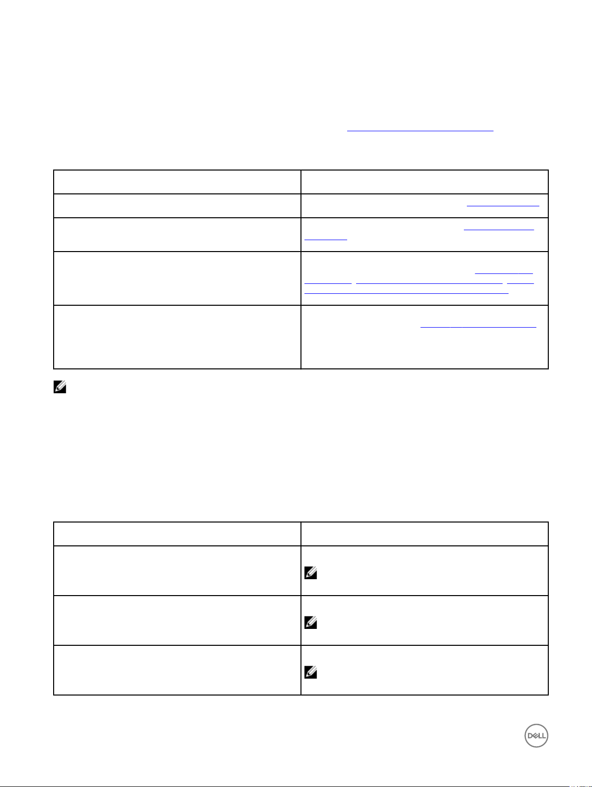
Acknowledgements button is added in the Copyright tab in System Information. This button is related to third party software
and is available only in following clients:
– Wyse 3030 LT with ThinOS
16
Page 17
– Wyse 3040 with ThinOS
– Wyse 5010 with ThinOS (D10D)
– Wyse 5040 AIO thin client (5212)
– Wyse 5060 with ThinOS
– Wyse 7010 with ThinOS (Z10D)
This feature is supported on the following PCoIP enabled clients:
– Wyse 3030 LT with PCoIP
– Wyse 3040 with PCoIP
– Wyse 5010 with PCoIP (D10DP)
– Wyse 5040 with PCoIP (5213)
– Wyse 5060 with PCoIP
• Event Log Tab — Displays the thin client start-up steps normally beginning from System Version to Checking Firmware or error
Messages that are helpful for debugging problems. The details about the monitors connected to the thin client are also displayed.
Following is the screenshot displaying the Event Log tab for Monitors details:
17
Page 18

• Status Tab — Displays status information about TCP performance related parameters, UDP performance related parameters,
CPU Busy, System Up Time, CCM status, Free Memory, Active sessions, and WDM status.
• IPv6 Tab — Displays IPv6 information such as Link-local Address, IPv6 Address and IPv6 Default Gateway.
NOTE: This tab is displayed when IPv6 is enabled in the General tab of the Network Setup dialog box, see
Conguring the Network Settings.
• ENET Tab— Displays information about wired network connections.
• WLAN Tab— Displays information about wireless network connections.
18
Page 19
3
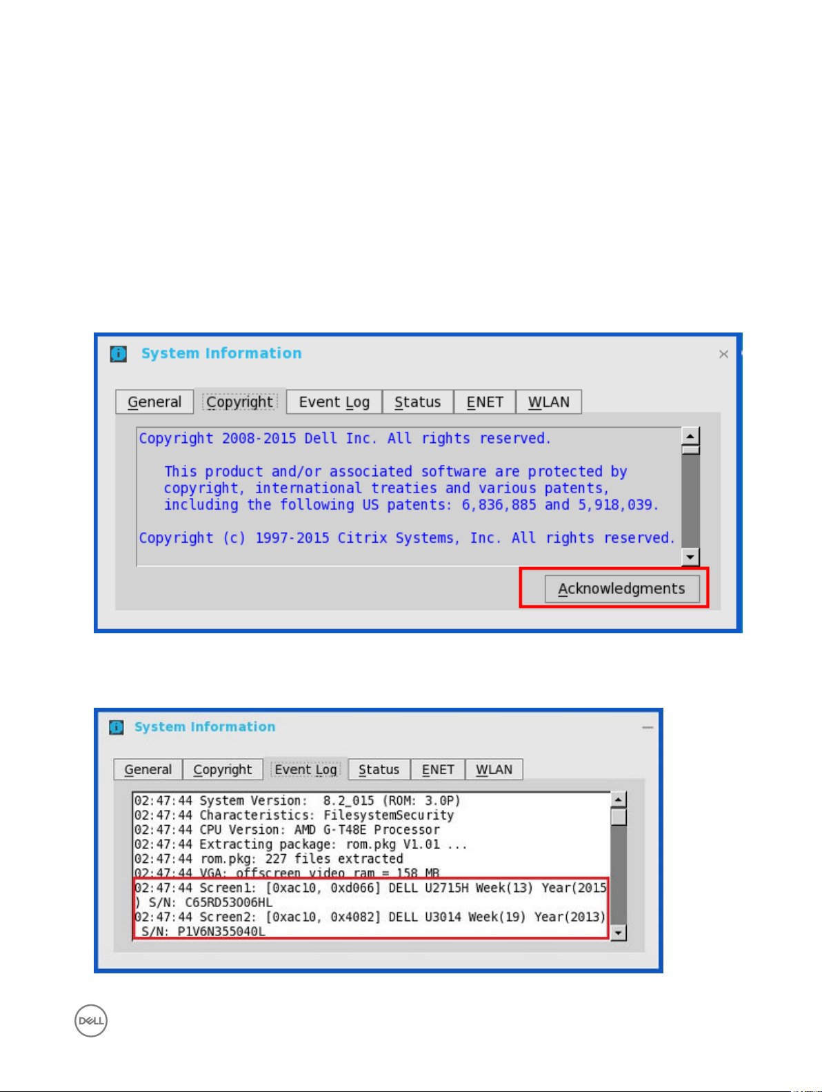
Global Connection Settings
If you do not use INI les to provide central conguration (global connection settings) to users, you can use the Global Connection
Settings dialog box to congure settings that aect all of the connections in your list of connections:
• Zero Desktop — Click Global Connection Settings in the List of Connections.
• Classic Desktop — Click Global Connection Settings in the Connect Manager.
To congure the Global Connection Settings:
1. On the desktop taskbar, click Connect Manager → Global Connection Settings.
The Global Connection Settings dialog box is displayed.
2. Click the Session tab to select the check boxes you want for the options that are available to all sessions.
The Smart Card check box species the default setting for connecting to a smart card reader at startup.
19
Page 20

NOTE:
ICA sessions always have automatic connection to attached smart card readers. When using the Disks check box for
automatic connection to connected USB sticks, use the following guidelines:
• More than one disk can be used at the same time, however, the maximum number of USB sticks including dierent
subareas is 12.
• Be sure to save all data and sign o from the session mapping the USB stick before removing the USB stick.
NOTE: USB devices redirection — By default, audio, video and printer devices will not use HDX USB for redirection.
You can make selections for USB device redirection on the Session tab of the Global Connection Settings dialog box.
3. Click the ICA tab to select the check boxes you want for the options that are available to all ICA sessions. Select the audio
quality optimized for your connection.
Map to — When a drive is entered, maps a disk under the drive.
4. Click the RDP and use the following guidelines:
• Enable or disable Network Level Authentication (NLA)— The NLA authentication method veries users before they are
allowed to connect with a full Remote Desktop connection.
• Enable or disable ForceSpan— This dual-monitor feature allows you to span the session horizontally across two monitors,
thus two monitors acting as one large monitor.
• Enable or disable Terminal Service multimedia Redirection (TSMM).
• Enable or disable Record from Local (recording from local microphone).
• Enable or disable RemoteFX.
• Select the USB Redirection Type (TCX USB or RDP USB)— TCX USB is the default. To use RDP USB, you must use a
RemoteFX session for Windows 7/Windows2008R2 session. However, RDP USB is not supported using a standard
Windows 7/Windows2008R2 session. For Windows 8 session and above, RDP USB is supported.
5. In PCoIP enabled clients, an additional tab named PCoIP is available. Select the USB device redirection type from the drop-
down list. The available values are
PCoIP USB and TCX USB.
20
Page 21

Conguring the Connectivity
This chapter helps you to understand various conguration settings for a secure connection. Connectivity menu includes:
• Conguring the Network Settings.
• Conguring the Remote Connections.
• Conguring the Central Congurations.
• Conguring the VPN Manager.
Important:
To congure the settings on Classic desktop, click System Setup from the desktop menu, and use the conguration tabs.
To congure the settings on Zero desktop, click the System Settings icon on the zero toolbar, and then use the conguration
tabs.
Conguring the Network Settings
To congure the network settings use the following options:
• Conguring the General Settings.
• Conguring the Options Settings.
• Conguring the ENET Settings.
• Conguring the WLAN Settings.
• Conguring the Proxy Settings.
4
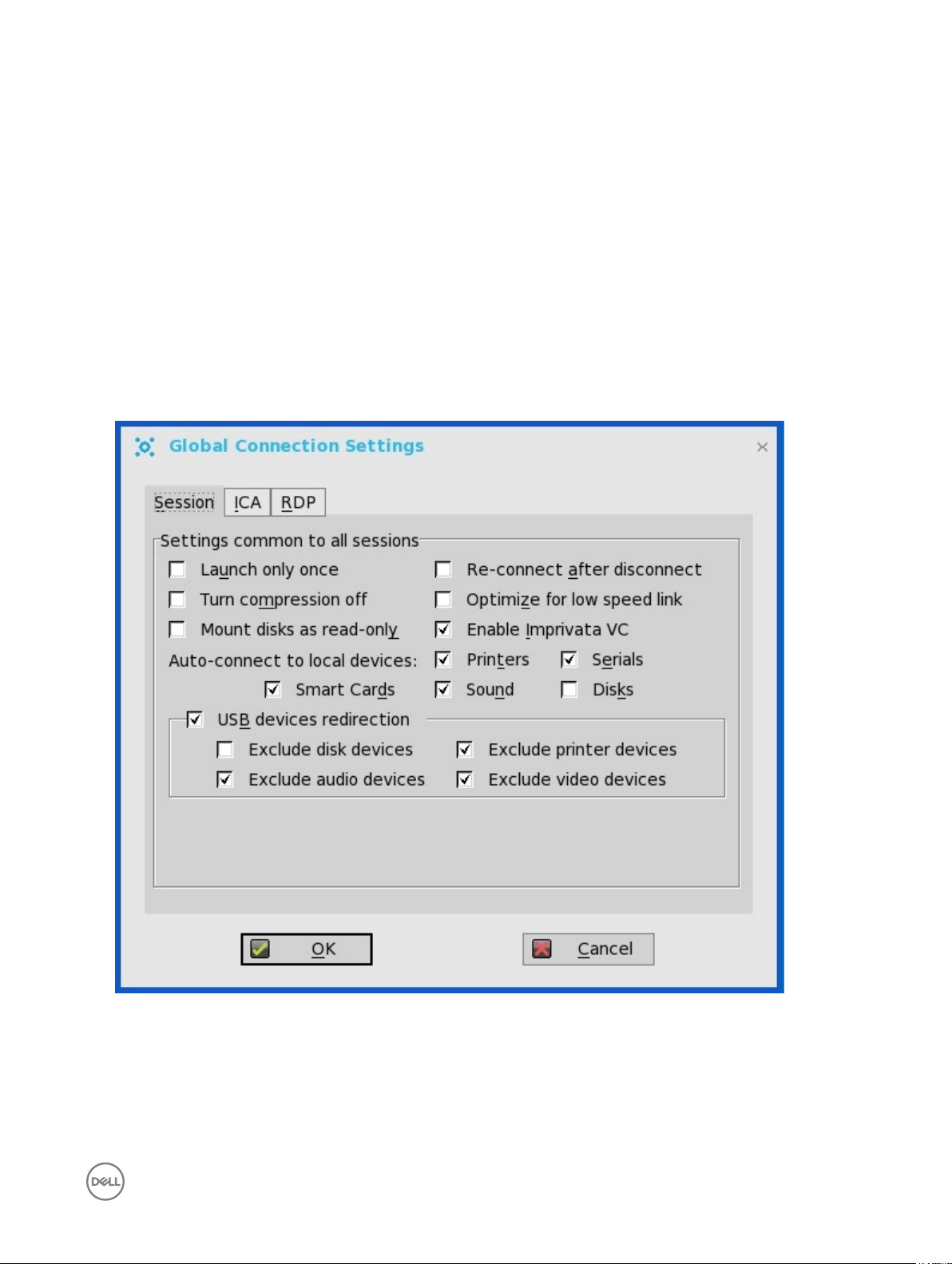
Conguring the General Settings
To congure the general network settings:
1. From the desktop menu, click System Setup, and then click Network Setup.
The Network Setup dialog box is displayed.
21
Page 22
2. Click the General tab, and use the following guidelines:
a. To set the default gateway, select the type of network interface from the available options.
1. Single Network support — Either wireless or wired network is connected.
• ENET — Click this option, if you want set up the Ethernet Wired Network Connection.
• WLAN — Click this option, if you want set up the Wireless Network Connection.
• If the user use wireless network after selecting ENET connection or wired network after selecting WLAN
connection, then the system log "WLAN: set default gate way xx.xx.xx.xx" for rst case and "ENET: set default
gate way xx.xx.xx.xx" for second case are printed to ensure that the UI setting reects the actual usage.
NOTE: The User Interface (UI) will not be changed automatically.
2. Dual Network support — Both wireless and wired networks are connected. The default gateway is determined by the
UI settings.
b. Use Static Name Servers— By default, this check box is not selected (OFF=dynamicfrom DHCP).
If name servers are changed using GUI, INI or link down/ up, then the details are displayed in Event Logs.
In dynamic mode, the DNS/WINS can be merged from Ethernet and Wireless, if network is not working.
c. Enter the URL address of the DNS Domain in the DNS Domain box.
d. Enter the IP address of the DNS Server in the DNS Server box.
Use of DNS is optional. DNS allows you to specify remote systems by their host names rather than IP addresses. If a
specic IP address (instead of a name) is entered for a connection, it is used to make the connection. Enter the DNS
Domain and the network address of an available DNS Server. The function of the DNS Domain entry is to provide a default
sux to be used in name resolution. The values for these two boxes may be supplied by a DHCP server. If the DHCP server
supplies these values, they replace any locally congured values. If the DHCP server does not supply these values, the
locally congured values will be used.
NOTE: You can enter up to 16 DNS Server addresses, separated by a semicolon, comma, or space. The rst
address is for the primary DNS server and the rest are secondary DNS servers or backup DNS servers .
e. Enter the IP address of the WINS Server in the WINS Server box.
Use of WINS is optional. Enter the network address of an available WINS name server. WINS allows you to specify remote
systems by their host names rather than IP addresses. If a specic IP address (instead of a name) is entered for a
22
Page 23
connection, it is used to make the connection. These entries can be supplied through DHCP, if DHCP is used. DNS and
WINS provide essentially the same function, name resolution. If both DNS and WINS are available, the thin client attempts
to resolve the name using DNS rst and then WINS.
You can enter two WINS Server addresses (primary and secondary), separated by a semicolon, comma, or space.
f. Enter the digit multiplier of 30 seconds in the TCP Timeout box to set the time-out value of a TCP connection. The value
must be 1 or 2 which means the connection time-out value is from 1x30= 30 seconds to 2x30= 60 seconds. If the data for
connecting to the server is not acknowledged and the connection is time out, setting the time-out period retransmits the
sent data and again tries to connect to the server till the connection is established.
3. Click OK to save the settings.
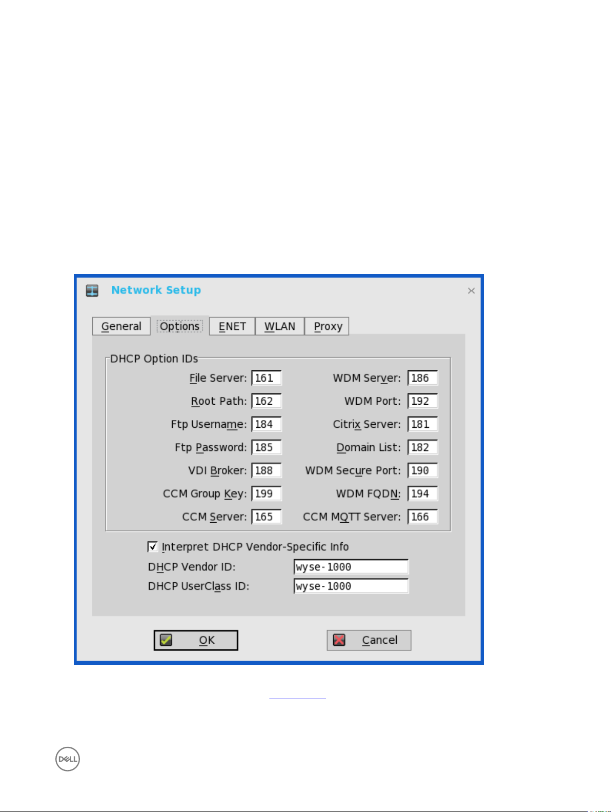
Conguring the DHCP Options Settings
To congure the options settings:
1. From the desktop menu, click System Setup, and then click Network Setup.
The Network Setup dialog box is displayed.
2. Click the Options tab, and use the following guidelines:
a. DHCP Option IDs — Enter the supported DHCP options. Each value can only be used once and must be between 128 and
254. For information about DHCP options, see DHCP Options.
b. Interpret DHCP Vendor-Specic Info — Select this check box for automatic interpretation of the vendor information.
c. DHCP Vendor ID — Shows the DHCP Vendor ID when the dynamically allocated over DHCP/BOOTP option is selected.
23
Page 24
d. DHCP UserClass ID — Shows the DHCP UserClass ID when the dynamically allocated over DHCP/BOOTP option is
selected.
3. Click OK to save the settings.
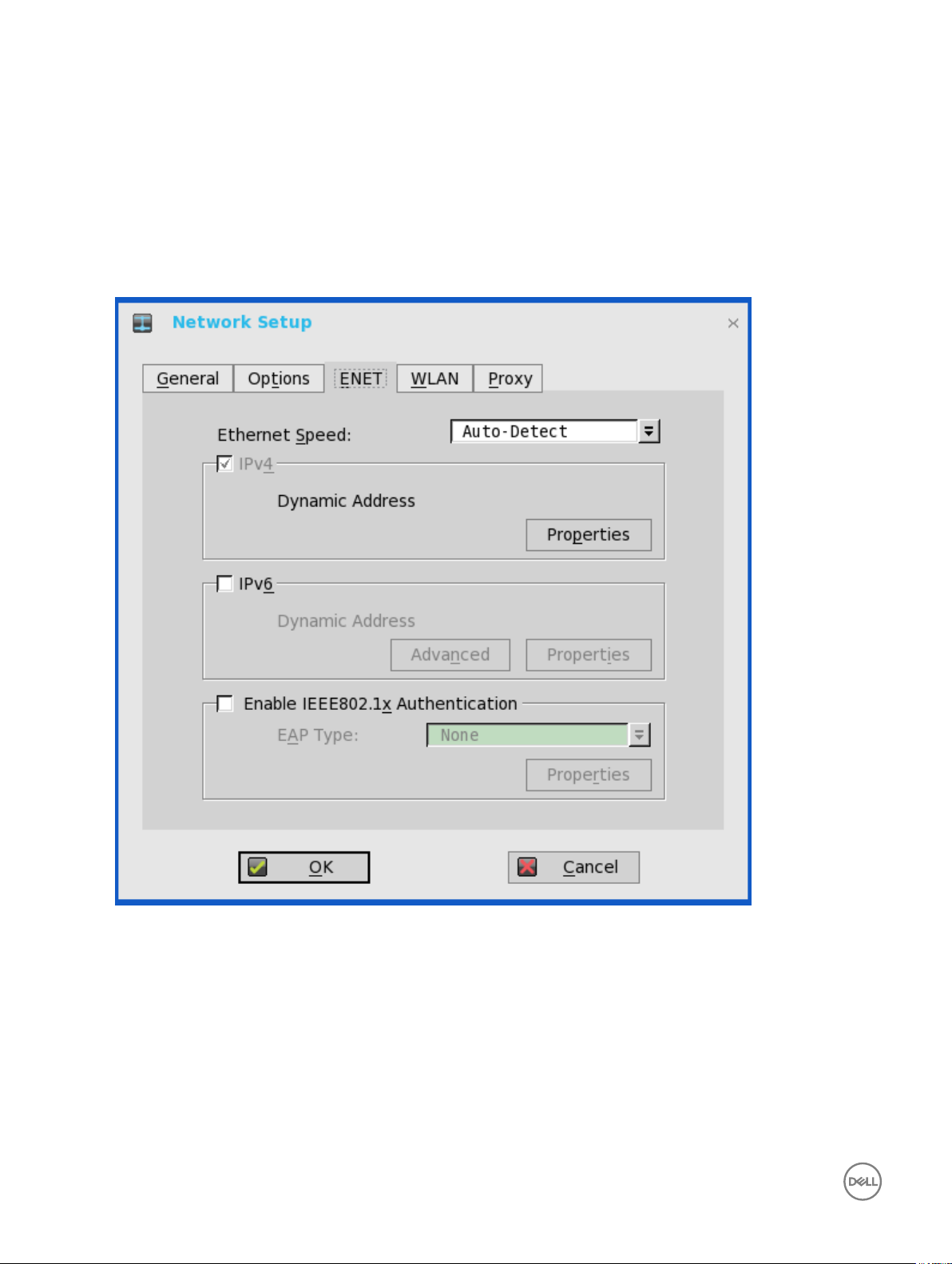
Conguring the ENET Settings
To congure the ENET settings:
1. From the desktop menu, click System Setup, and then click Network Setup.
The Network Setup dialog box is displayed.
2. Click the ENET tab, and use the following guidelines:
a. Ethernet Speed — Normally the default (Auto-Detect) should be selected, but another selection can be made if automatic
negotiation is not supported by your network equipment. Selections include Auto-Detect, 10 MB Half-Duplex, 10 MB Full-
Duplex, 100 MB Half-Duplex, 100 MB Full-Duplex, and 1 GB Full-Duplex.
The 10 MB Full-Duplex option can be selected locally at the device, however, this mode may need to be negotiated through
AutoDetect.
b. The IPV4 check box is selected by default. Click Properties to set various options supported by IPV4.
• Dynamically allocated over DHCP/BOOTP — Selecting this option enables your thin client to automatically receive
information from the DHCP server. The network administrator must congure the DHCP server using DHCP options to
provide information. Any value provided by the DHCP server replaces any value entered locally on the Options tab,
however, locally entered values are used if the DHCP server fails to provide replacement values.
24
Page 25

• Statically specied IP Address — Select this option to manual enter the IP Address, Subnet Mask and Default
Gateway:
– IP Address — Must be a valid network address in the server environment. The network administrator must provide
this information.
– Subnet Mask — Enter the value of the subnet mask. A subnet mask is used to gain access to machines on other
subnets. The subnet mask is used to dierentiate the location of other IP addresses with two choices: same subnet
or other subnet. If the location is other subnet, messages sent to that address must be sent through the Default
Gateway, whether specied through local conguration or through DHCP. The network administrator must provide
this value.
– Default Gateway — Use of gateways is optional. Gateways are used to interconnect multiple networks (routing or
delivering IP packets between them). The default gateway is used for accessing the internet or an intranet with
multiple subnets. If no gateway is specied, the thin client can only address other systems on the same subnet.
Enter the address of the router that connects the thin client to the internet. The address must exist on the same
subnet as the thin client as dened by the IP address and the subnet mask. If DHCP is used, the address can be
supplied through DHCP.
c. Select the IPV6 check box, and then click Advanced to select various IPV6 supported setting options from the available
check boxes.
d. Click properties and use the following guidelines:
• Wait DHCP — Selecting this option enables your thin client to wait for IPV6 DHCP before the sign-in, if not selected
the system will only wait for IPV4 DHCP if enabled.
• Dynamically allocated over DHCP/BOOTP — Selecting this option enables your thin client to automatically receive
information from the DHCP server. The network administrator must congure the DHCP server (using DHCP options)
to provide information. Any value provided by the DHCP server replaces any value entered locally on the Options tab,
however, locally entered values are used if the DHCP server fails to provide replacement values.
• Statically specied IP Address — Select this option to manually enter the IP Address, Subnet Mask and Default
Gateway.
– IP Address — Must be a valid network address in the server environment. The network administrator must provide
this information.
– Subnet Mask — Enter the value of the subnet mask. For more information, see various options supported by IPV4
in this section.
– Default Gateway — Use of gateways is optional. For more information, see various options supported by IPV4 in
this section.
• DNS Servers — Use of DNS is optional. DNS allows you to specify remote systems by their host names rather than IP
addresses. If a specic IP address (instead of a name) is entered for a connection, it rather than DNS is used to make
the connection. Enter the network address of an available DNS Server. The value for this box may be supplied by a
DHCP server. If the DHCP server supplies this value, it replaces any locally congured value. If the DHCP server does
not supply this value, the locally congured value is used.
e. Select the check box to enable IEEE802.1x Authentication.
• EAP Type — If you have enabled the Enable IEEEE 802.1x authentication check box, select the EAP Type option you
want (TLS, LEAP PEAP or FAST).
• TLS — If you select the TLS option, click Properties to open and congure the Authentication Properties dialog box.
– Select the Validate Server Certicate check box because it is mandatory to validate your server certicate.
NOTE:
The CA certicate must be installed on the thin client. Also note that the server certicate text eld supports a
maximum of approximately 127 characters, and supports multiple server names.
– If you select the Connect to these servers check box, the box is enabled where you can enter the IP address of
server.
25
Page 26

– Click Browse to nd and select the Client Certicate le and Private Key le you want.
The following kinds of server names are supported — all examples are based on Cert Common name company.wyse.com
NOTE:
Using only the FQDN, that is company.wyse.com does not work. You must use one of the options (note that
*.wyse.com is the most common option as multiple authentication servers may exist): servername.wyse.com
*.wyse.com
*wyse.com
*.com
f. LEAP — If you select the LEAP option, click Properties to open and congure the Authentication Properties dialog box.
Be sure to use the correct Username and Password for authentication. The maximum length for the username or the
password is 64 characters.
g. PEAP — If you select the PEAP option, click Properties to open and congure the Authentication Properties dialog box.
Be sure to select either
Validate Server Certicate is optional.
NOTE:
The server certicate text box for LEAP and PEAP supports a maximum of approximately 127 characters, and
supports multiple server names.
h. FAST—If you select the FAST option, click Properties to open and congure the Authentication Properties dialog box. Be
sure to select either EAP_GTC or EAP_MSCHAPv2, and then use the correct Username, Password and Domain. Validate
Server Certicate is optional.
i. To congure EAP-GTC, enter the username only. The password or PIN is required when authenticating.
To congure EAP-MSCHAPv2, enter the username, password and domain.
EAP_GTC or EAP_MSCHAPv2, and then use the correct Username, Password and Domain.
Important: The domain/username in the username box is supported, but you must leave the domain box blank.
The CA certicate must be installed on the thin client and the server certicate is forced to be validated. When EAPMSCCHAPV2 is selected in EAP type in the Authentication Properties dialog box (for PEEP IEEE802.1x authentication), an
option to hide the domain is available for selection. Username and Password boxes are available for use, but the Domain text
box is disabled.
3. Click OK to save the settings.
Conguring the WLAN Settings
1. From the desktop menu, click System Setup, and then click Network Setup.
The Network Setup dialog box is displayed.
2. Click the WLAN tab, and use the following guidelines:
26
Page 27
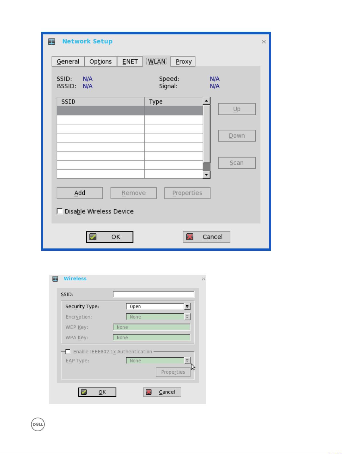
a. Add— Use this option to add and congure a new SSID connection.
You can congure the SSID connection from the available security type options.
27
Page 28
b. After you congure the SSID connection, the added SSID connection is listed on the page of the WLAN tab.
c. Remove — Use this option, if you want to remove a SSID connection by selecting the SSID connection from the list.
d. Properties — Use this option to view and congure the authentication properties of a SSID connection that is displayed in
the list.
e. Select the Disable Wireless Device check box, if you want to disable a wireless device.
From ThinOS 8.3, EAP-FAST authentication is supported. During the initial connection, when there is a request for a Tunnel PAC
from the authenticator, the PAC is used to complete the authentication. Therefore, the rst time connection always fails and the
following connections succeed.
New User Interface (UI): Wireless → EAP Type → EAP - FAST; Second authentication method supports MSCHAPv2/GTC
•
only for EAP-FAST.
• Only automatic PAC provisioning is supported in this release. The user/machine PAC provisioning generated with Cisco EAP-
FAST utility is not supported.
3. Click OK to save the settings.
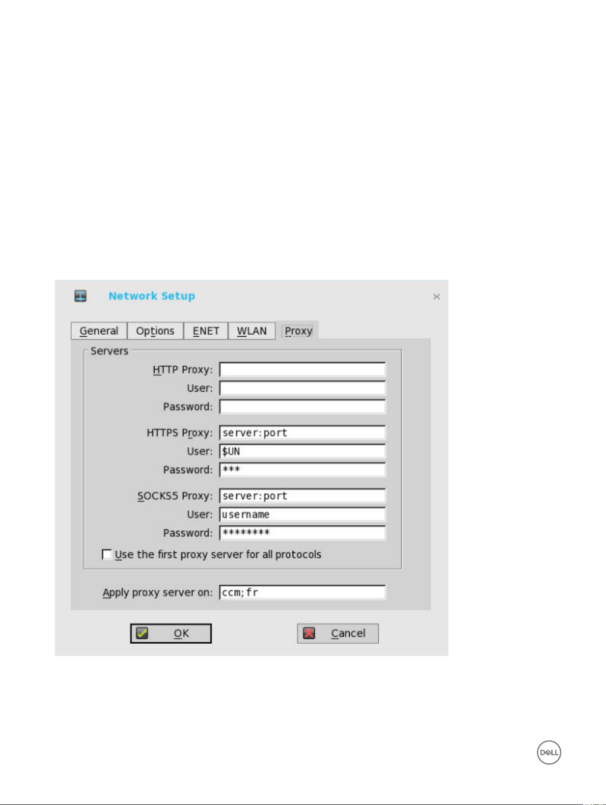
Conguring the Proxy Settings
The network Proxy tab is added to support Cloud Client Manager (CCM) and HDX Flash Redirection.
Supported Protocols
• For HDX FR, HTTP and HTTPS protocols are supported.
28
Page 29

– If both are congured, the HDX FR works with HTTPS proxy.
– User credential pass through is possible with $UN/$PW.
• For CCM, HTTP, HTTPS and Socks5 (recommended) protocols are supported.
1. From the desktop menu, click System Setup, and then click Network Setup.
The Network Setup dialog box is displayed.
2. Click the Proxy tab, and use the following guidelines:
a. Enter the HTTP proxy port number or HTTPS proxy port number, Username and Password in the respective elds.
However, Credential pass through ($UN/$PW) is not recommended because it starts before user sign on.
CCM uses both HTTP/HTTPS and MQTT protocols to communicate with CCM/MQTT server. However, the HTTP proxy
cannot redirect TCP packages to MQTT server which requires a Socks5 proxy server. If there is only HTTP server
available, then the real-time command that requires MQTT will not work.
HTTP/HTTPS proxy default port is 808, and SOCK5 proxy default port is 1080.
b. Select the Use the rst proxy server for all protocols check box to allow all the protocols to use the same server in HTTP
Proxy elds. Both HTTP and HTTPS proxy use the same host and port, and Socks5 proxy agent uses HTTP host with
default Socks 5 port (1080).
c. If SOCKS5 proxy is congured, then CCM proxy uses the SOCKS5 only. If SOCKS5 is not congured, then CCM proxy
searches for alternative protocols, for example, HTTP in the conguration.
d. Specify the supported applications as CCM and FR in the Apply proxy server on eld.
3. Click OK to save the settings.
User Scenarios
1. Congure correct proxy server host and port.
2. Congure the user credentials according to the proxy server settings.
3. On system restart, the client checks in to the CCM server through Socks5 proxy server.
4. MQTT connection is established through Socks5 proxy server.
5. Real-time commands work ne through Socks5 proxy server.
6. Connect to the Citrix desktop, congure proxy in internet options of the browser, and then playback HDX FR through the
HTTP/HTTPS proxy authentication.
Conguring the Remote Connections
Use the Remote Connections dialog box to congure thin client remote connections including ICA, RDP, Citrix XenDesktop,
Microsoft, VMware View, Dell vWorkspace, and other broker server connections. This dialog box also enables you to congure visual
options, and general connection settings.
• Conguring the Broker Setup
• Conguring the Visual Settings
• Using the General Options
• Conguring the Authentication Settings
NOTE:
In the Classic Desktop option, the Remote Connections dialog box allows you to create default ICA and RDP connections for
use. If you want to create several ICA and RDP connections (more than the default connections), use the Connect Manager,
For more information see Using the Connect Manager.
29
Page 30
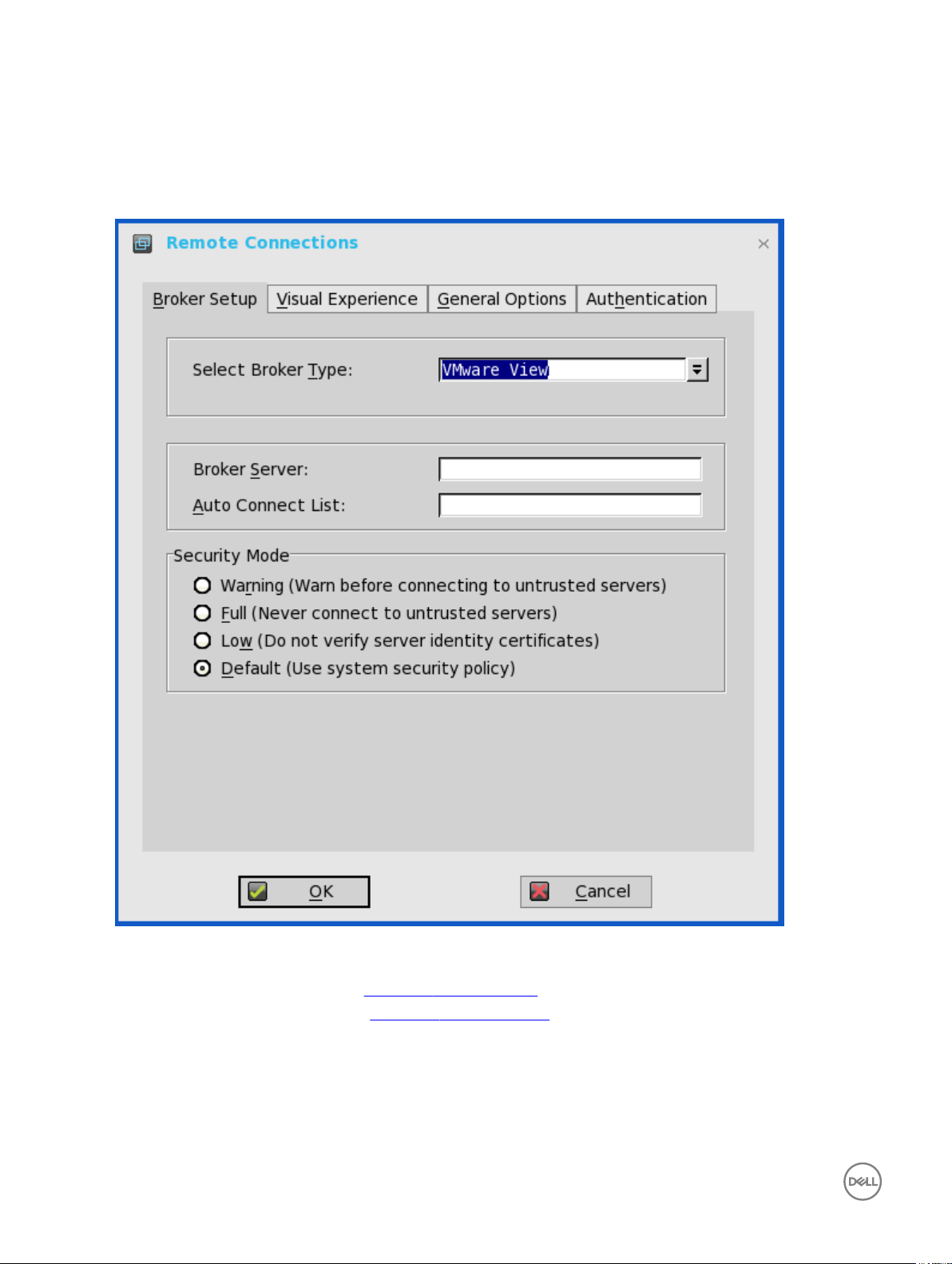
Conguring the Broker Setup
To congure the Broker setup:
1. From the desktop menu, click System Setup, and then click Remote Connections.
The Remote Connections dialog box is displayed.
2. Select Broker type from the drop-down list.
a. If you select None from the list, click either of the following connection protocols:
• ICA — For more information, see Conguring ICA Connections.
• RDP — For more information, see Conguring RDP Connections.
b. If you select the Citrix Xen, use the following guidelines:
• Select the check box to enable the StoreFront style.
• Broker Server— Enter the IP address/Hostname/FQDN of the Broker Server.
30
Page 31

• Auto Connect List—Enter the name of the desktops that you want to launch automatically after logging in to the
respective broker. More than one desktop can be entered. Each desktop name is separated by semi-colon, and is casesensitive.
• Select the check box to enable automatic reconnection at logon.
NOTE:
If you enable the automatic reconnection, you are able to select from the reconnection options. Click either of the
options where you can connect to the disconnected sessions only or connect to both active and disconnected
sessions.
• Select the check box to enable automatic reconnection from the button menu.
NOTE: If you enable the automatic reconnection, you are able to select from the reconnection options. Click
either of the options where you can connect to the disconnected sessions only or connect to both active and
disconnected sessions.
• Account Self-Service Server— Enter the IP address of the Account self-service server.
• XenApp — Use this option, if you want to set default settings to XenApp.
• XenDesktop— Use this option, if you want to set default settings to XenDesktop.
c. If you select the VMWare view, use the following guidelines:
• Broker Server— Enter the IP address/Hostname/FQDN of the Broker Server.
• Auto Connect List—Enter the name of the desktops that you want to launch automatically after logging in to the
respective broker. More than one desktop can be entered. Each desktop name is separated by semi-colon, and is casesensitive.
• Security mode—Select the preferred Security mode from the following options:
– Warning —Warn Security requires FQDN address with self-signed certicate, or without any certicate, but
corresponding warning message is displayed for user to continue.
– Full—Full Security requires FQDN address with domain certicate.
– Low—Security allows FQDN/IP address with/without certicate.
– Default— Follows global security mode settings.
For PCoIP enabled clients, an additional Connection Protocol drop-down list for protocol selection is available. By default,
the option is set to Server Default.
From the Connection Protocol drop-down list, select the type of protocol connection. The available options are:
• Server Default— Select this protocol connection to display the desktop with default protocol as congured in the
VMware View Admin console, for each pool in the broker. If a desktop pool is congured with default protocol as RDP in
the View Admin console, then only the RDP connection of the desktop is displayed in ThinOS after users sign in to the
device.
• All Supported—Select this protocol connection to display the desktop in both RDP and PCoIP connections, when a
desktop pool is congured to allow users to select protocol as yes. If a desktop is congured with default protocol as
PCoIP and allow user to select protocol as no, then ThinOS only displays the desktop in PCoIP connection.
• RDP only— Select this protocol connection to display only the desktop in RDP connection. If a desktop pool is
congured with default protocol as PCoIP in the View Admin console, and allow user to select protocol as no, then this
desktop is not displayed in ThinOS after user signs in to the device.
• PCoIP only—Select this protocol connection to display only the desktop in PCoIP connection, for each pool in the
broker. If a desktop pool is congured with default protocol as RDP in the View Admin console, and allow user to select
protocol as no, then this desktop is not displayed in ThinOS after user signs in to the device.
For more information about VMware Horizon View broker, see Using the VMware Horizon View broker and PCoIP.
d. If you select the Microsoft, use the following guidelines:
• Broker Server—Enter the IP address/Hostname/FQDN of the Broker Server.
31
Page 32

• Auto Connect List—Enter the name of the desktops that you want to launch automatically after logging in to the
respective broker. More than one desktop can be entered. Each desktop name is separated by semi-colon, and is casesensitive.
e. If you select Dell vWorkspace, use the following guidelines:
• Broker Server— Enter the IP address/Hostname/FQDN of the Broker Server.
• Auto Connect List—Enter the name of the desktops that you want to launch automatically after logging in to the
respective broker. More than one desktop can be listed. Each desktop name is separated by a semi-colon, and is casesensitive.
• Select the check box to enable vWorkspace Gateway.
• vWorkspace Gateway— Enter the IP Address of the vWorkspace Gateway.
f. If you select Other, you must enter the IP address of the Broker server in the Broker Server box.
g. If you select the Amazon Workspaces, use the following guidelines:
32
NOTE: Amazon Workspaces connection is applicable only for PCoIP clients running ThinOS 8.3 and later
versions.
• Broker Server— Enter the IP address/Hostname/FQDN of the Broker Server.
• Auto Connect List—Enter the name of the desktops that you want to launch automatically after logging in to the
respective broker. More than one desktop can be listed. Each desktop name is separated by a semi-colon, and is casesensitive.
• Security mode—Select the preferred Security mode from the following options:
Page 33

– Warning —Warn Security requires FQDN address for domain certicate installed in PCM. If certicate is not
installed on the client, corresponding warning message is displayed for you to continue.
– Full—Full Security requires FQDN address with domain certicate installed in PCM, and certicate installed on the
client.
– Low—Security allows FQDN/IP address with/without certicate.
– Default— Follows global security mode settings.
• Connection Protocol— The drop-down list is disabled for AWS broker. By default, the option is set to PCoIP Only.
For information about deploying AWS WorkSpaces and AWS EC2 PCM for AWS WorkSpaces, go to www.teradici.com/
web-help/Connecting_ZC_AWS_HTML5/TER1408002_Connecting_ZC_AWS.htm#03_DeployPCM.htm%3FTocPath
%3D3.
For information about conguring the Broker Server address = “URI (https://<FQDN or IP address>) of the PCM”, go to
www.teradici.com/web-help/Connecting_ZC_AWS_HTML5/TER1408002_Connecting_ZC_AWS.htm#05_Connect.htm
%3FTocPath%3D5.
Known issues with Amazon Web Services/Workspaces
• Key combination Ctrl + Alt disconnects users from AWS session intermittently with old agent in AWS desktop. To x this
issue, update to latest agent by rebooting the desktop.
• Each user is assigned with one WorkSpaces desktop, and therefore logon with any username returns to the single
desktop and then the session connects automatically. Disconnecting from the desktop returns user to logon screen.
3. Click OK to save the settings.
VMware Horizon View broker and PCoIP
VMware Horizon View Broker timeout— The VMware Horizon View Broker timeout does not force the user to sign out from the
broker anymore when the secure tunnel is enabled.
In earlier version of ThinOS, when the broker times out, the user session is disconnected and the user is logged out from the broker.
From ThinOS 8.2 release, ThinOS disconnects the user session from the broker, but does not force user logout. This is because the
user has local connections other than the broker desktop, and these connections are active when the broker timeout is reached.
PCoIP session NUM/CAP keyboard status synchronizes with session instead of thin client—This is applicable for session startup
only. The PCoIP session keyboard NUM/ CAP status synchronizes from remote session to client, whereas RDP/ ICA synchronize
status from local to remote session.
For example,
1. Set keyboard NUM=off in current PCoIP session.
2. Disconnect the session.
3. Set client keyboard NUM=on.
4. Reconnect to the PCoIP session.
5. The keyboard NUM status in both session and client is updated to NUM=off.
RDS desktop through PCoIP—You can view and connect to the Remote Desktop Service (RDS) desktop through the PCoIP
protocol in the broker using PCoIP enabled ThinOS clients. In VMware Horizon View 6.0 and later versions, the RDS desktop has
RDP and PCoIP connections based on server congurations.
NOTE: The RDS Application over PCoIP is not supported.
The RDS desktop protocol switch message dialog box is provided in this release. A typical user scenario is as follows:
1. Connect to the RDS desktop through protocol. For example, RDP.
2. Disconnect from the desktop.
33
Page 34

3. Connect to the same RDS desktop through another protocol. For example, PCoIP.
The message dialog box is displayed, allowing you with an option to continue.
The options available are:
• Cancel— You can end the PCoIP connection, and connect to the desktop in RDP again.
• Log Out and Reconnect— You can connect to the desktop through PCoIP, and the earlier session in RDP is logged out.
USB redirection RDS desktop through PCoIP— This feature is supported.
Supporting the VMware Real Time Audio-Video
Use the Real-Time Audio-Video feature to run Skype and other online conference applications on the remote desktop. Using this
feature, both audio and video devices that are connected to your thin client are available to use for VoIP in remote desktop.
To know more about the VMware Real Time Audio-Video support, go to pubs.vmware.com/horizon-62-view/topic/
com.vmware.horizon-view.desktops.doc/GUID-D6FD6AD1-D326-4387-A6F0-152C7D844AA0.html.
NOTE: There is no additional conguration for ThinOS. RTAV video requires RTME package to be installed on your
device.
To validate the VMware Real Time Audio-Video, do the following:
1. Connect to the VMware PCoIP desktop with the audio and video devices.
NOTE: USB redirection must be disabled for the audio/video devices.
2. Verify the audio playback of the system using the VMware Virtual Audio.
34
Page 35

3. Verify the system audio recording using the VMware Virtual Microphone.
4. Verify the Audio settings in VoIP application.
35
Page 36

5. Verify the Video settings in VoIP application using the VMware Virtual Webcam.
6. Start the audio/video calls.
Dependencies and Known Issues
• Dependency: RTME.i386.pkg needs to be installed for RTAV video.
• The answer call button of the local audio device, supported by HDX RTME, is not supported by RTAV.
• RTAV does not support RDS desktop, for example, 2008R2/ 2012R2 according to VMware.
• Support for PCoIP protocol only. RDP protocol is not supported according to VMware.
36
Page 37

• Webcam preferences are not supported. For example, the rst webcam displayed in the Camera tab in local peripheral settings is
used always.
• Camera/Video: High Denition video is not supported because of the RTAV limitation. The local camera setting does not aect
RTAV video because of the application design. Dell recommend users not to interfere with the local camera settings.
Citrix Icon Refresh
Citrix applications can be refreshed by clicking Refresh from PNMenu.
There are two methods to refresh the Citrix applications:
• Manual refresh
• Auto refresh using the INI parameter
Refreshing Citrix Applications Manually
To refresh the Citrix application manually, do the following:
1. For single StoreFront or PNAgent server, change the application in broker, and then click Refresh from PNMenu.
The following message is displayed in the lower right pane during application refresh.
2. Applications are refreshed in Session bar list, Connect Manager list and App menu list.
The following log is displayed in the Event Log window:
ICA: refresh store “xxx”…” or “ICA: refresh PNAgent”xxx”…
3. For MultiFarm (StoreFront or PNAgent servers) or Multilogon (StoreFront or PNAgent servers), select a single server to
refresh or click Refresh All to refresh all servers.
37
Page 38

NOTE:
Warning message is displayed when you open or edit or remove applications when you refresh the applications.
4. Refresh scope covers the aspects such as, application removed, added, duplicated, disabled, enabled, icon/title change, and
on/o desktop.
Active sessions that are started are not aected by application refresh.
5. The disconnect session can be reconnected after application refresh, if Automatic reconnection at logon is enabled in remote
connection.
Refreshing the Citrix Applications Automatically Using INI Parameter
To automatically refresh the Citrix application, set the following INI parameter:
SessionConfig=ICA RefreshTimeOut=dd:hh:mm
For example, 01:01:22, means the application will start refresh automatically, every 1 day: 1 hour: 22 minutes.
Limitations of Citrix Icon Refresh
Following are the limitations of Citrix icon refresh:
• Citrix icon refresh is supported in classic mode and storefront mode only.
• Virtual Desktop Infrastructure (VDI) mode is not supported.
Conguring the Visual Settings
To congure the visual settings:
1. From the desktop menu, click System Setup, and then click Remote Connections.
The Remote Connections tab is displayed.
2. Click Visual Experience tab, and use the following guidelines:
38
Page 39

NOTE: The Visual Experience tab is grayed out, if the StoreFront Style check box is selected for a Citrix Broker
Server entered in the Broker Setup tab.
a. Classic Desktop — Displays the full taskbar, desktop and Connect Manager familiar to ThinOS users. This option is
recommended for terminal server environments and for backward compatibility with ThinOS 6.x versions.
b. Zero Launchpad — Displays the new launch pad style GUI designed for VDI use. Functionality is accessed through an
always available interface. This option is recommended for VDI and any full-screen only connections. Toolbar, hotkey and
connection icon options are also available for conguration.
If you select the Zero Launchpad, then use the following guidelines:
• Select the check box to enable Zero Toolbar activation in left pane.
– Select the button if you want to enable Zero Toolbar activation in left pane when you pause a mouse on the screen.
– Select the button if you want to enable Zero Toolbar activation in left pane only after clicking.
• Select the check box to disable hotkey to show toolbar.
• Select the check box to always disable toolbar when you have one session available.
• Select the check box to disable Home Icon.
3. Click OK to save the settings.
39
Page 40

Conguring the General Options
To congure the general options:
1. From the desktop menu, click System Setup, and then click Remote Connections.
The Remote Connections dialog box is displayed.
2. Click the General Options tab, and use the following guidelines:
a. Click the available options to select the action after you exit all open desktops. The available options are None, Sign-o
automatically, Shut down the system automatically and Restart the system automatically.
NOTE: By default, None is selected and the thin client automatically returns to the terminal desktop.
b. Default Sign-on Username— Enter the Default user name.
c. Default Sign-on password— Enter the Default password.
d. Default Sign-on Domain— Enter the Default Domain.
e. Click Clear locally saved connections to clear locally saved connections.
NOTE: If you enter all three default sign-on credentials (Username, Password and Domain), you are automatically
logged on to your desktop upon system start.
Conguring the Authentication settings
To congure the authentication settings:
1. From the desktop menu, click System Setup, and then click Remote Connections.
The Remote Connections dialog box is displayed.
40
Page 41

2. Click the Authentication tab, and select the authentication type.
Three types of authentication are displayed.
• Imprivata— Conguring the Imprivata OneSign Server.
• Caradigm—Conguring the Caradigm Server.
• SECUREMATRIX— Conguring SECUREMATRIX.
• HealthCast—Introduction to HealthCast.
3. After conguring your preferred authentication, click OK to save the settings.
Conguring the Imprivata OneSign Server
OneSign Virtual Desktop Access provides a seamless authentication experience and can be combined with single sign-on for No
Click Access to desktops and applications in a virtual desktop environment.
41
Page 42

To congure the OneSign Server, enter the details of the OneSign Server (either https://ip or https://FQDN values), reboot the
client to display the logon dialog box, and then enter credentials to open the VDI broker dialog box for logon use. You can also set this
feature in your INI le, see Dell Wyse ThinOS INI Reference Guide.
The following OneSign features or actions are supported:
• Client and Broker Authentication
– Citrix Xen App
– Citrix Xen Desktop
– VMware View
• Kiosk Mode
• Fast User Switching
• Non-OneSign user VDI access
• Hotkey Disconnect
• Proximity card reader redirection
• Guided Question and Answer login
• Authenticate w/Password
• Authenticate w/Password + Password Change
• Authenticate w/Password + Password Change | New Password is Invalid
• Authenticate w/Proximity Card + Password
• Authenticate w/Proximity Card + Pin
• Authenticate w/Proximity Card + Pin | Pin not enrolled
• Authenticate w/Proximity Card Alone | Retrieve Password
• Retrieve User Identity Password
• Reset User Identity Password
• Update User Identity Password
• Enroll Proximity Card
• Lock/Unlock Terminal with Proximity CardLock/Unlock Terminal with Proximity Card
For details on Deployment in an Imprivata OneSign ProveID Environment, see Knowledge Base Solution #23254 . Go to
www.dell.com/wyse/knowledgebase and search for 23254.
ThinOS supports latest Imprivata WebAPI version 5. It includes OneSign Objects (WebAPI v4) and Fingerprint Authentication
(WebAPI v5).
From ThinOS 8.3.1 Hot Fix release, Imprivata SSO solution is supported for ARM platforms—Wyse 3010 thin client and Wyse 3020
thin client series.
Conguring objects on Imprivata Server
Imprivata WebAPI is updated from v4 to v5. From earlier version, supports conguration objects are supported that enables you to
control dierent aspects of client behavior. The Imprivata WebAPI feature is available on OneSign server 4.9 and later versions. The
Conguration objects control dierent aspects of the client behavior.
Use the following guidelines to congure the objects on Imprivata Server:
1. Conguring the General conguration object
a. On the Imprivata server, click Computer policy, and then click General tab.
b. Select the check box to allow users to shut down and restart workstation from lock screen.
42
Page 43

NOTE: Display shutdown button and restarts commands to the user on the OneSign GINA.
The following conguration objects are supported on Imprivata server:
• Shutdown Allow
– If you enable this feature by selecting the check box, the shutdown and restart icon is shown in ThinOS login and
locked windows.
– If you clear the check box, the shutdown and restart icon is grayed out.
• FailedOneSignAuth Allow—
Only yes or no options are supported. Non-OneSign user can log in to the Broker by clicking No radio button.
• Logging Allow
– OneSign logs could output on ThinOS with this feature. An INI conguration is needed correspondingly.
– Loglevel=0/1/2/3. The default value is 0. If set to 0, logs are not displayed.
• Display name format — Account name can be shown correctly with dierent formats in pop-up notications.
2. Conguring the Walkway conguration object
On the Imprivata server, click Computer policy, and then click the Walk Away tab.
• Key mouse inactivity enabled and behavior — The check box in addition to keyboard and mouse inactivity is not
supported.
• Passive proximity cards
– If you want to use proximity card to lock the computer, select the Tap to lock check box.
– If you want to lock the computer and log in as a dierent user. select the Switch users check box.
43
Page 44

– INI parameter isTapToLock=0/1/2.
•
– Lock warning enabled and type— The three types that are supported are: none, notication balloon and Screensaver.
* None — No warning messages are displayed.
* Notication balloon— ThinOS displays a notication window.
* Screensaver— Hide the display contents before the workstation locks.
– Warning message— The message can be customized.
– Lock Screen type —Only obscure type is supported.
– Hot key to lock workstation or log o user— ThinOS can support following keys:
“F1 ~ F12”, "BKSP", “DEL”, “DOWN”, “END”, “ENTER”, “ESC”, “HOME”, “INS”, “LALT”, “LEFT”, “LCONTROL”,
“NUMLOCK”, “PGDN”, “PGUP”, “RCONTROL”, “RIGHT”, RTALT”, “SPACE”, “TAB”, “UP”, “a~z”, “A~Z”, “0~9” and
modier “+”, “%”, “^” (Shift, Alt and Control)
– Suspend action — The server conguration controls this feature on ThinOS. Therefore a new INI is added—
SuspendAction=0/1; 0 means lock, 1 means signo.
3. Conguring the SSPR Conguration Object
The SSPR conguration object controls the Self-Service Password Reset behavior for a user. The enabled attribute species
whether the user is allowed to reset their password as part of emergency access. The mandatory attribute species whether
the user must reset their password as part of emergency access.
4. Conguring the RFIDeas conguration object
The RFIDeas conguration object controls the behavior of the RFIDeas readers. The conguration can be congured by two
ways, the computer policy of OneSign server and ThinOS INI.
5. Conguring the Custom background conguration object
On the Imprivata server, click Computer policy, and then click the Customization tab.
Custom background image impacts the wallpaper of ThinOS sign-on screen.
6. Conguring the Co-Branding conguration object
On the Imprivata server, click Computer policy , and then click Customization.
44
Page 45

Logo image impacts all the dialog boxes in ThinOS with raw logo.
7. Conguring the SSPR Customization Conguration object
• The text displayed in sign-on UI and lock window can be customized.
• The largest size supported by ThinOS is 17 characters.
ThinOS UI:
8. Password Self-Services force enrollment feature
Selecting this check box allows you to reset the primary authentication password.
45
Page 46

INI conguration for Imprivata OneSign Server
A new INI parameter is added to the OneSignServer=AutoAccess=command. The new value is AutoAccess=Local. When
AutoAccessis set to local, the ThinOS ignores the brokers that are set on the Imprivata OneSign Appliance and starts the broker/
connections which are dened in wnos.ini or local dened on the client. You can start the vWorkspace, Microsoft, and other ThinOS
connections while supporting Imprivata user authentication.
Proximity card enrollment
1. Tap the proximity card. The card enrollment page is displayed.
2. Enter the credentials and then click OK.
46
Page 47

Proximity card is enrolled successfully.
Imprivata Bio-metric Single Sign-On
Fingerprint identication feature is highly reliable, and cannot be easily replicated, altered, or misappropriated.
The prerequisites of OneSign server are:
• Imprivata v4.9 or later appliance version is needed that supports the WebAPI v5 and later versions.
• Fingerprint identication license is required.
Notes on Imprivata Bio-metric Single Sign-On
• ARM platforms (T/TD) are not supported.
• Supported protocols are RDP, ICA, and PCoIP.
47
Page 48

• Required Fingerprint reader devices are:
– ET710 (PID 147e VID 2016)
– ET700 (PID 147e VID 3001)
Supported Scenarios
1. Signing/Unlocking the ThinOS Devices using Fingerprint Authentication.
• Congure the OneSign server on ThinOS, and then plug-in the ngerprint reader device.
• The ThinOS Fingerprint window is displayed automatically after OneSign server is initialized.
• Fingerprint authentication works on the ThinOS unlock window.
2. Unlocking the Virtual Desktop using Fingerprint Authentication.
• Enable the Imprivata Virtual Channel from ThinOS Global Connection Settings.
48
Page 49

• When you lock the virtual desktop in the session, the Fingerprint window is displayed automatically.
49
Page 50

3. Managing Fingerprints on virtual desktop.
• Legend Fingerprint Management is supported.
• Fingerprint management with Imprivata Conrm ID enabled is not supported. This requires both supervisor and user to
nish the enrollment and it is recommended to use Windows platform to perform this action.
To manage ngerprints, do the following:
a. Right-click the OneSign agent icon in System tray.
b. Click Manage Fingerprints, and enter the correct credentials in the displayed window to manage your Fingerprints.
50
Page 51

Conguring the Caradigm Server
Caradigm Single Sign-on and Context Management (SSO & CM) is the product of the Caradigm Company which provides Single
Sign-on and Context Management Services. Caradigm solution has been integrated since ThinOS 8.1.
To congure the Caradigm integration on ThinOS, do the following:
1. From the desktop menu, click System Setup, and then click Remote Connections.
The Remote Connections dialog box is displayed.
2. Click the Authentication tab, and then click Caradigm.
51
Page 52

a. SSO & CM Server—Enter the IP addresses of the Single Sign-On (SSO) and Context Management (CM) Servers.
b. Default Group Name—Type the name of the default group in the Default Group Name box.
c. Enable logo remote desktop
• Select the check box to log o the current user from the session before system sign-o.
• Clear the selection to disconnect from the session.
3. Click OK to save the settings.
Conguring the Caradigm Vault Server
To congure the Caradigm Vault Server on ThinOS:
1. From the desktop menu, click System Setup, and then click Remote Connections.
The Remote Connections dialog box is displayed.
2. Click the Authentication tab, click the Caradigm button, enter the IP address of the SSO & CM Server, and then click OK.
3. On the Caradigm Vault Server, use the following guidelines:
• Ensure that the Enroll unenrolled badges option is checked.
• Make sure that all Badge ID mapping entries are deleted.
52
Page 53

4. Click SSO&CM → Advanced Congurations , and use the following guidelines:
a. Ensure that the Enable Proximity Support check box is selected.
b. Ensure that the Enable way2care check box is selected.
5. To prepare a certicate to the Caradigm Vault Server, use the following guidelines:
The Caradigm Vault Server uses the certicate to validate the connection between the Tap Server and the thin client.
a. To raise a request for the certicate:
• The certicate should be issued by your Certicate Authority.
• Prepare the certicate in two formats:
– PFX format which has a private key.
– The other is PEM format which is text-based, Base64-encoded DER le. For Example, Caradigm.cer, Caradigm.pfx.
b. To import a certicate to the thin client, use either of the following two options:
• Click System Setup → System tools → Certicates to import certicates from USB storage or le server.
• Use INI le to import certicate.
AddCertificate=client_cert.pfx password=passpass
c. To add a certicate to Vault server:
53
Page 54

Use the Thin Client Certicates page to add certicates for the thin client devices. The certicate must be a text in PEM
format, that is, a text-based Base64-encoded DER le.
• Open the DER cert le on Notepad.
• Log in to the Vault Server Admin Console, and then click Appliance → Thin Client Certicates.
• Copy the Notepad text to the Vault server
Conguration on VDI Server and Desktops
Caradigm solution of ThinOS supports the multi-types of VDI server such as VMware View Horizon 6, Citrix XenApp 6.5, Citrix
XenDesktop 5.6 and Citrix XenDesktop 7.6.
To congure the VDI server and desktop:
• Install the Caradigm desktop components in the servers and desktops.
• Indicate vault server IP, and then provide a valid security token.
• Add following lines to Service section of the \programdata\sentillion\vergence\Authenticator.ini conguration le.
TapServerIdentification=True
RemotePromptForPassword=Badge
NOTE:
At present, the following PCoIP enabled thin clients oer Caradigm SSO over PCoIP:
• Wyse 3030 LT with PCoIP
• Wyse 3040 with PCoIP
• Wyse 5010 with PCoIP (D10DP)
• Wyse 5040 AIO with PCoIP (5213)
• Wyse 5060 with PCoIP
SSO and CM client installed on your VDI server and desktops must be upgraded to latest version 6.2.5 in order to support this
feature.
Conguring SECUREMATRIX
SECUREMATRIX enhances the security of enterprise and cloud-based applications while providing seamless end user experience for
a one-time password (OTP) that can be used for authentication with desktops, Windows, VPNs, intranets, extranets, web servers,
e-commerce and other network resources.
To congure the SECUREMATRIX Server , enter either https://ip or https://FQDN values, reboot the client to display the log on
dialog box, and then enter credentials to open the VDI broker dialog box for logon use. You can also set this feature in your INI le,
see Dell Wyse ThinOS INI Guide. For details see SECUREMATRIX documentation.
Introduction to HealthCast
HealthCast Single Sign-On (SSO) solution is designed to improve user convenience, streamline workow, and strengthen security
compliance in demanding environments. The same proximity cards used for physical access are used to tap-in and tap-out of unique
user sessions and to tap-over any sessions unintentionally left open on the ThinOS devices. Typically, you must type in your password
only one time each day and use your proximity cards to streamline workow and save time as they move between shared computers
54
Page 55

securely. Also, proximity cards can be secured with a PIN, if congured by the organization. The HealthCast SSO solution also
supports user self-service password reset so that you can reset your own passwords without the need to call the help desk.
NOTE: HealthCast SSO Solution on ThinOS is a client-server solution. ThinOS provides the client-side functionality, but
you must also install and congure the HealthCast Server components on a server system in order for the solution to
work properly. Contact HealthCast on
requirements, and conguration information.
HealthCast website for one or more server installation executables, server
Conguring HealthCast on ThinOS
HealthCast Web API Server is integrated with ThinOS release to implement the HealthCast SSO solution. To use the HealthCast
SSO solution, ThinOS must be congured to use the HealthCast Web API Server. You can do this by using the INI le (wnos.ini), or
using the ThinOS UI. Dell recommends you to use the INI le for large deployments.
ThinOS UI conguration
• To use the HealthCast Web API, congure the HealthCast settings on the thin client side. To congure, do the following:
a. From the desktop menu, click System Setup , and then click Remote Connections.
The Remote Connections dialog box is displayed.
b. Click the Authentication tab, and then click HealthCast.
55
Page 56

Figure 1. Authentication tab
c. Enter the HealthCast server details in the box provided.
d. To import the client certicate, click Browse, and select the appropriate certicate you want to use.
56
Page 57

e. Click OK to save the settings.
INI conguration
To congure using INI parameters, add the following INI parameters to your wnos.ini le:
• HealthCastServer— The server address and options needed for the client to connect to the HealthCast Web API Server.
HealthCastServer=<https address> SecurityMode=<default, full, warning, low> ClientCerticate=<cert-pfx-le-name>
For example: HealthCastServer=https://server1.example.com SecurityMode=full ClientCerticate=client-cert.pfx.
For more information on INI parameters, see Dell Wyse 8.3.2 INI Reference Guide.
HealthCast SSO features and functionality on ThinOS
The following are the HealthCast SSO features and functionality on ThinOS:
• Proximity card enrollment
– HealthCast supports user self-enrollment. Therefore, there is no need to bring the proximity card to a special registration
station, or for IT sta to be involved. Instead, you must only tap the disenrolled proximity card at a terminal and you can
follow the easy registration process. This is a one-time event after which you can use the card wherever HealthCast is
installed.
57
Page 58

Figure 2. Proximity card enrollment
• Manual login and lock/unlock terminal
– If you do not have a card, or choose not to use your card, then you can manually log in using your user name and password.
Administrators can disable manual login, if they wish, so that users can sign on with their proximity cards. You can also lock or
unlock the terminal, if you have signed on with a manual login.
Figure 3. Manual login and lock/unlock terminal
• Proximity card login and lock/unlock terminal
– After the proximity card is registered, tap the card at a terminal to login.
58
Page 59

Figure 4. Login
You can lock the session to secure it, but leave the remote session connected for fast access when you return. To do this, tap
the proximity card and the session is locked.
Figure 5. Lock terminal
To resume the session, tap the card again.
59
Page 60

• Walk away
– Terminals can be congured to lock or log o sessions that have been left open. The time that will elapse before automatic
lock or log o can be set by an administrator using the convenient web administration application.
• Tap-Over
– If a session is locked or left open, a second user can tap their own proximity card and this will disconnect the rst session and
log the second user into their own unique session.
• Forgotten card
– If you forget your card at home, you can receive a temporary card and register it for the day using the same easy registration
process mentioned above.
• Lost or stolen card
– If you report a card as lost or stolen, an administrator can immediately disable the card using the convenient web
administration application. This prevents anyone else from using it.
• Self-Service Password Reset (SSPR)
– If SSPR enabled by an administrator, you can register for SSPR and reset your passwords without calling the help desk.
Figure 6. SSPR enrollment
• Easy to use web-based administration tool
– Administrators can quickly and easily congure settings, manage proximity cards, and users using a web-based administration
tool.
Conguring the Central Congurations
Use the Central Conguration dialog box to congure thin client central connection settings such as le server, optional WDM
server settings, and optional Cloud Client Manager.
Use the following options to congure the central congurations:
• Conguring the General Central Congurations.
• Conguring the WDA Settings.
60
Page 61

Conguring the General Central Congurations
To congure the general central congurations:
1. From the desktop menu, click System Setup, and then click Central Conguration.
The Central Conguration dialog box is displayed.
2. Click General tab, and use the following guidelines:
File Servers/Path, Username and Password — Enter the IP address or host name of the le server that provides the system
software and update images. The address can be supplied through DHCP, if DHCP is used.
a. File Servers/Path — Allows maximum of 128 characters. The data species part of the path to be used when the server is
accessed. Multiple le servers/paths may be named, as long as all data ts in the length limitation.
b. Username — Enter the username to log in to the le server. Use maximum of 15 characters.
c. Password — Enter the password to log in to the le server. Use maximum of 15 characters.
3. Click OK to save the settings.
Conguring the WDA Settings
Use this tab to congure the WDM and CCM settings.
61
Page 62

To congure the WDA settings, do the following:
1. From the desktop menu, click System Setup, and then click Central Conguration.
The Central Conguration dialog box is displayed.
2. Click WDA, and use the following guidelines.
WDM is selected by default. WDA service automatically runs after the client boot up.
If the rst discovery, for example, the WDM service is not successful, then it seeks for the next priority, for example, CCM
service. This continues till a discovery is successful. If all discoveries fail, then it is started again automatically after a xed time
(24 hours).
a. WDM Servers — Enter the IP addresses or host names, if WDM is used. Locations can also be supplied through user
proles, if user INI proles are used.
b. DNS Name Record — (Dynamic Discovery) Allows devices to use the DNS host name lookup method to discover a WDM
Server.
c. DHCP Inform — (Dynamic Discovery) Allows devices to use DHCP Inform to discover a WDM Server.
d. Enable Automatic Discovery After Missed Check-ins — Select the number of missed check-ins after which you want the
auto discovery options enabled.
3. Click OK to save the settings.
62
Page 63

Service checked in status is displayed in System Information.
The following is the INI parameter for this feature:
WDAService={yes(default),no}Priority ={WDM(default),CCM,“WDM;CCM”,“CCM;WDM”}
To congure the CCM settings, do the following:
1. Click CCM, and use the following guidelines.
a. Enable Cloud Client Manager (CCM) — Select the check box to enable the Cloud Client Manager (CCM).
63
Page 64

b. DNS SRV record—Select this check box if you want the thin client to obtain CCM values through DNS server, and then
try to register into the CCM server. By default, the check box is selected. If the check box selection is canceled, then the
thin client will not try to obtain the CCM values through DNS server.
To create DNS records in DNS server, use the following information:
#CCM server URL
DNS Record Type: DNS SRV
Record Name: _WMS_MGMT._TCP.<Domain>
Value Returned: WDMNG Server URL
Example: _WMS_MGMT._TCP.WDADEV.com
# MQTT Server URL
64
Page 65

DNS Record Type: DNS SRV
Record Name: _WMS_MQTT._TCP.<Domain>
Value Returned: CCM Server URL
Example: _WMS_MQTT._TCP.WDADEV.com
# Group Token
DNS Record Type: DNS Text
Record Name: _WMS_GROUPTOKEN.<Domain>
Value Returned: Group Token (as String)
Example: _WMS_GROUPTOKEN .WDADEV.com
# CA Validation
DNS Record Type: DNS Text
Record Name: _WMS_CAVALIDATION.<Domain>
Value Returned: TRUE or FALSE (as String)
Example: _WMS_CAVALIDATION.WDADEV.com
c. Group Registration Key — Enter the Group Registration Key as congured by your cloud Client Manager administrator
for the desired group.
NOTE: If you enable the Cloud Client Manager (CCM ), make sure that you have entered the Group Registration
Key and enabled the CCM Advanced Settings.
2. Click OK to save the settings.
From ThinOS 8.3.1 Hot Fix release, the following additional CCM features are supported:
• Support for the ThinOS client login to CCM server console.
• Support for the ThinOS client packages installation by using On-Premises Services in CCM server console.
Conguring the VPN Manager
VPN Manager is included in ThinOS 8.1 to manage VPN connections. A virtual private network (VPN) extends a private network
across a public network such as the Internet. It enables a computer or Wi-Fi-enabled device to send and receive data across shared
or public networks as if the devices are directly connected to the private network, while beneting from the functionality, security
and management policies of the private network.
To congure the VPN Manager, use the following guidelines:
1. In Classic Mode, from the desktop menu, click System Setup → VPN Manager .
65
Page 66

In Zero Mode, user can view the VPN Manager tab in System Settings panel.
2. Click VPN Manager.
66
Page 67

The VPN Manager dialog box is displayed.
3. Click New to create a new session.
a. Session Name (up to 21 characters) – Enter the name of the Session Name. This is not a mandatory option. If the eld is
left blank, the VPN server name will be used as the session name.
b. VPN server (up to 63 characters) – Enter the IP address of the VPN Server. This is dened as either an IP address or a host
name. This is a mandatory option.
c. Login Username (up to 31 characters) – Enter the Login Username. This is a mandatory option.
d. Login Password (up to 31 characters) – Enter the password of the user. This is not a mandatory option.
e. Select the check box to Auto-connect on system startup.
f. Select the check box to show progress in detail.
g. Click OK.
67
Page 68

When the connections are created, the description column lists the session name and the Auto column shows which
connection is automatically connected when the unit restarts. Only one session can be set to auto-connect.
4. Click Connect.
The connection status is displayed.
68
Page 69

5
Conguring Thin Client Settings
You can congure available thin client settings on the thin client using the following. Depending on user privilege level, some dialog
boxes and options may not be available for use.
• Local Settings Menu
• Reset Features
NOTE:
While it is not recommended to use dialog boxes for conguring thin client settings, they are available in case you want to
temporarily override central default congurations or you do not have the option to set up central conguration (smaller
environments). In general, it is recommended that you use central conguration to enable you to automatically push updates
and any desired default conguration to all supported thin clients in your environment, see Central Conguration: Automating
Updates and Congurations.
Local Settings Menu
Local Settings menu items include:
• Conguring the System Preferences
• Conguring the Display settings
• Conguring the Peripherals Settings
• Conguring the Printer Settings
To access the Local Settings menu:
• Zero Desktop — Click the System Settings icon on the Zero Toolbar. Administrators can also click the Admin Mode button on
the Login dialog box.
• Classic Desktop — Click User Name, and select System Setup.
NOTE: User Name is the user who is logged-on and is at the lower-left pane of the taskbar.
Conguring the System Preferences
Use the System Preference dialog box to select personal preferences such as screen saver, time/date and custom information
settings.
Use the following options to congure the System Preferences:
• Setting the General System Preference
• Setting Time and Date
• Setting the Custom Information
Setting the General System Preference
To congure the general settings for system preference:
1. From the desktop menu, click System Setup, and then click System Preferences.
69
Page 70

The System Preference dialog box is displayed.
2. Click the General tab, and use the following guidelines:
a. Screen Saver — Allows you to select the type of screen saver you want. The default is to Turn O Screen.
Other selections available include Flying Bubbles , Moving Image and Showing Pictures which are screen savers with the
monitor remaining on.
b. Timer — Select a time after which the screen saver is to be activated; either disable, 1 minute, 5 minutes, 10 minutes
(default), 15 minutes, or 30 minutes.
When the thin client is left idle for the specied idle time, the screen saver is initiated.
c. Locale — Select a language to be activated for the user login-experience; either French, German, or default English.
NOTE: Locale changes the language for the user login-experience screens only displayed during boot-up and
login and not the conguration or administrator screens.
Only the following messages are applicable for French locales:
• Username/Password/Domain
• System Information
• Shut down the system, restart the system, reset the system setting to factory default
• OK, Cancel
• Initiating devices
• Looking up IP address from DHCP, Note: Pressing CTRL-ESC keys cancel out of network check
• Retry DHCP for an IP address
• Waiting for network link. Verify that network cable is plugged into back of unit
• Check Cable, No Ethernet link
• Leave administrator mode
• Connecting
• Sign o from account
70
Page 71

• Lock Terminal, Unlock Password
• Terminal is locked, Invalid unlock password
d. Terminal Name — Allows entry of a name for the thin client. The default is a 14-character string composed of the letters
WT followed by the thin client Ethernet MAC address.
Some DHCP servers use this value to identify the IP address lease in the DHCP Manager display.
3. Click OK to save the settings.
Setting the Time and Date
To congure the Time and Date settings:
1. From the desktop menu, click the System Setup, and then click System Preferences.
The System Preference dialog box is displayed.
2. Click the Time/Date tab, and use the following guidelines:
a. Time Zone— Select a time zone where the thin client operates from the drop-down list. Default value is Unspecied.
b. Enable Daylight Saving— Allows you to enable the daylight saving settings. When selected, the Start Date and End Date
boxes must be properly congured to dene the daylight saving starting (month/week/day) and ending (month/week/day)
periods.
Use the following guidelines to enter the Start date and End date:
• Month— Species the month in the year from January through December.
• Week— Select 1 through 4 for the week in the month. Week last denotes the last week in the month.
• Day — Species the day of the week from Monday through Sunday.
c. Time Format — Allows you to select a 12 or 24-hour time format. default is 24-hour format.
d. Date Format — Allows you to select a yyyy/mm/dd (year/month/day) or dd/mm/yyyy (day/month/year) date format.
Default is yyyy/mm/dd.
e. Time Servers — List of IP addresses or host names with optional TCP port number of Time Servers.
Each entry with optional port number is specied as Name-or-IP: port, where: port is optional. If not specied, port 80 is
used. Locations can be supplied through user proles if user proles are used. The Time Servers provide the thin client time
71
Page 72

based on the settings of time zone and daylight saving information. If DHCP is used, locations can be supplied through
DHCP.
f. Change Date and Time — Allows you to change date and time for secure environments requiring a solution to outside
server access. When connecting to a le server over HTTPS, the proper time must be dened on the thin client for SSL/
certication validation.
3. Click OK to save the settings.
Setting the Custom Information
Use the Custom Info tab to enter conguration strings for use by WDM software. The conguration strings can contain information
about the location, user, administrator, and so on.
To set the custom information:
1. From the desktop menu, click System Setup, and then click System preferences.
The System preference dialog box is displayed.
2. Click the Custom Info tab to enter conguration strings used by WDM software. The conguration strings can contain
information about the location, user, administrator, and so on. Clicking OK transfers the custom eld information you enter in the
dialog box to the Windows registry. The information is then available to the WDM Client Manager. For more information on using
Custom Fields and using WDM for remote administration and upgrading thin client software, see
WDM documentation.
3. Click OK to save the settings.
Conguring the Display Settings
Use the Display dialog box to select the resolution and refresh rate for the monitor used with the thin client.
Use the following options to congure the Display Settings:
• Conguring the General Display Settings
• Conguring the Dual Head Settings
72
Page 73

Conguring the General Display Settings
To congure the general display settings:
1. From the desktop menu, click System Setup, and then click Display.
The Display dialog box is displayed.
2. Click the General tab, and use the following guidelines:
a. Select best display setting on DDC monitor—If the monitor is VESA DDC2B (Display Data Channel) compatible, selection
of this option allows the thin client to automatically select the best resolution and refresh rate.
If your monitor is not DDC compatible, then Monitor does not support Plug and Play message is displayed. Click OK to
acknowledge the message and remove it from the screen.
b. DDC table— If the monitor is VESA DDC2B (Display Data Channel) compatible, selection of this option allows you to select
the resolution and refresh rate you want from the list.
c. User dened display setting— Select this option and select the resolution and refresh rate supported by your monitor. All
combinations are allowed.
Resolutions include:
640 x 480 (not on Wyse 3020 thin client with ThinOS—T10D)
800 x 600 (not on Wyse 3020 thin client with ThinOS—T10D)
1024 x 768
1152 x 864
73
Page 74

1280 x 720
1280 x 768 (not on Wyse 3010 thin client with ThinOS—T10)
1280 x 1024
1360 x 768 (not on Wyse 3010 thin client with ThinOS and Wyse 3020 thin client with ThinOS—T class)
1366 x 768
1368 x 768 (not on Wyse 3010 thin client with ThinOS and Wyse 3020 thin client with ThinOS—T class)
1400 x 1050
1440 x 900
1600 x 900
1600 x 1200
1680 x 1050
1920 x 1080
1920 x 1200
1920 x 1440
2560 x 1080
2560 x 1440
2560 x 1600
3840 x 2160
Refresh rate list selections include:
60 Hz (default)
75 Hz
85 Hz
d. Rotation —Select a rotation option; either None, Left turn 90 degrees, or Right turn 90 degrees.
e. Desktop Color— Only 32 bit is permitted from ThinOS 8.2. This value is selected by default.
f. Usage Help — This section contains brief instructions for using the Display dialog box and running the test. No operator
entry can be made in this box.
Make note of the instructions in the area, regarding v-key reset usage in case of display failure.
3. Click OK to save the settings.
Supported monitor resolutions—The following are the list of tested monitor resolutions:
Table 3. Supported monitor resolutions
Monitor resolutions Wyse 5060 thin client Wyse 3040 thin client
640 x 480 Supported Supported
800 x 600 Supported Supported
1024 x 768 Supported Supported
74
Page 75

Monitor resolutions Wyse 5060 thin client Wyse 3040 thin client
1152 x 864 Supported Supported
1280 x 720 Supported Supported
1280 x 768 Supported Supported
1280 x 1024 Supported Supported
1360 x 768 Supported Supported
1366 x 768 Supported Supported
1368 x 768 Supported Supported
1400 x 1050 Supported Supported
1440 x 900 Supported Supported
1600 x 900 Supported Supported
1600 x 1200 Supported Supported
1680 x 1050 Supported Supported
1920 x 1080 Supported Supported
1920 x 1200 Supported Supported
2560 x 1080 Supported Supported
2560 x 1440 Supported Supported
2560 x 1600 Supported Supported
3440 x 1440 Supported Not Supported
3840 x 2160–Dual 4K Supported
Dual 3840 x 2160 is supported with Dual
Display ports for 30 Hz display refresh
rate.
The following are the tested Dell monitors for Wyse 5060 thin client, supporting dual 3840 x 2160 resolution:
Dell P2815Q (3840 x 2160)
Dell UP3216Q (3840 x 2160)
Not Supported
Conguring the Dual Head Display Settings
To congure the Dual head display settings:
1. From the desktop menu, click System Setup, and then click Display.
The Display dialog box is displayed.
2. Click Dual Head tab, and use the following guidelines:
75
Page 76

This feature is applicable for supported Dual Monitor Capable Thin Clients Only.
a. Dual Head—Select Mirror Mode to have the two monitors work in a matching state, or Span Mode to have the two
monitors work separately second is extended from rst.
b. Main Screen—Select which of the two monitors you want to be the main screen (Screen1 or Screen2). The other screen
is extended from the main screen.
The other screen is extended from the main screen. When using a DVI to DVI/VGA splitter with VGA and DVI monitors at
the same time, the VGA monitor will be the primary monitor.
c. Layout—Select how you want the two monitors to be oriented to each other.
Horizontal — where you move between the monitors from the left and right of the screens.
Vertical— where you move between the monitors from the top and bottom of the screens.
d. Alignment— Select how you want the monitors to be aligned Bottom, Center, or Top.
Bottom means screens are bottom-aligned in a horizontal orientation; Center means screens are center-aligned; Top means
screens are top-aligned in a horizontal orientation.
e. Taskbar (Classic Desktop Only)—Select under which screen you want the Taskbar to appear Whole Screen or Main
Screen
Gamma Supported Monitors Only— Use the Gamma Setup tab to adjust the saturation values for Red, Green and Blue on
VGA connected monitors supporting gamma settings, if you feel the default settings are too light. Be aware that the Gamma
Setup tab will be disabled once you click Save+Exit. You can enable it again by setting rgamma={1-100} ggamma={1-100}
bgamma={1-100} in the Resolution INI parameter. For more information, see Dell Wyse ThinOS INI Guide.
76
Page 77

For Swap dual screens, when you set Main Screen to Screen2, an additional check box is displayed at the bottom of the tab
that allows you to swap dual screens. If you clear the check box, the Screen1 is usually the left one or the top one in dual
display. When you set Main Screen to Screen2, the main screen is changed to the right screen or bottom screen. If you
select the swap dual screens check box, you are able to set Main Screen to Screen2, but still have it at the left side or the
top side, which is considered more user friendly.
Conguring the Peripherals Settings
The Peripherals dialog box enables you to congure the settings for the Keyboard, Mouse, Audio, Serial, Camera, Touch Screen, and
Bluetooth.
• Conguring the Keyboard Settings
• Conguring the Mouse Settings
• Conguring the Audio Settings
• Conguring the Serial Settings
• Conguring the Camera Settings
77
Page 78

• Conguring the Touch Screen Settings
• Conguring the Bluetooth Settings
Conguring the Keyboard Settings
To congure the Keyboard settings:
1. From the desktop menu, click System Setup, and then click Peripherals.
The Peripherals dialog box is displayed.
2. Click the Keyboard tab and set the Character Set, Keyboard Layout, Delay Before Repeat and Repeat Rate parameters. The
following table explains the parameters present on the Peripherals dialog box.
Parameter
Character Set Species the character set. Each character is represented by
a number. The ASCII character set, for example, uses the
numbers 0 through 127 to represent all English characters and
special control characters. European ISO character sets are
similar to ASCII, but they contain additional characters for
European languages.
Keyboard Layout Presently the keyboard languages listed in the Keyboard
layout drop-down list are supported. The default value is
English (United States).
Delay Before Repeat Species the repeat parameters for held-down key. Select the
Delay before repeat value as either 1/5 second, 1/4 second,
1/3 second, 1/2 second, 3/4 second, 1 second, 2 seconds,
or No Repeat. The default is 1/3 second.
Repeat Rate Select Slow, Medium, or Fast. The default value is Medium.
3. Click OK to save the settings.
Description
78
Page 79

Conguring the Mouse Settings
To congure the Mouse settings:
1. From the desktop menu, click System Setup, and then click Peripherals.
The Peripherals dialog box is displayed.
2. Click the Mouse tab to select the mouse speed and mouse orientation.
3. Select the Swap left and right mouse buttons check box to swap mouse buttons for left-handed operations.
4. Click OK to save the settings.
Conguring the Audio Settings
To congure the audio settings:
1. From the desktop menu, click System Setup, and then click Peripherals.
The Peripherals dialog box is displayed.
2. Click the Audio tab to select the volume settings for connected devices.
79
Page 80

a. Click the Playback Devices tab to select the type of the audio from the drop-down menu.
• Use slider to control the volume settings for the playback devices.
• Select the check box to mute.
b. Click the Recorded Devices tab to select the type of the record from the drop-down menu.
• Use slider to control the volume settings for the record devices.
• Select the check box to mute.
c. The Recorder tab allows you to do the following tasks:
• Collect information about the speaker and microphone currently being used.
• Examine the performance of the speaker and microphone currently being used.
• Export the recorded audio sample to a USB key for archiving and further analysis.
For example, the connected USB headsets are displayed in the drop-down. Select the HD Audio option for analog earphone
use, the Speaker check box to enable the internal speaker, and the Boost check box for audio enhancement.
d. Select the Speaker check box to connect the speaker.
e. Select the Boost check box to boost the connected devices.
Conguring the Serial Settings
To congure the Serial settings:
1. From the desktop menu, click System Setup, and then click Peripherals.
The Peripherals dialog box is displayed.
2. Click the Serial tab and do the following:
80
Page 81

a. Select Port—Click the button to select the Port. Default is COM 1
b. Baud Rate — Select the Baud Rate from the drop-down list. Default is 9600.
c. Parity — Click the button to select the Parity.
d. Stop— Click the button to select the stop bits 1, 1.5, 2. Default value is 1.
e. Size—Click the button to select the Character size 5, 6, 7, or 8 bits. Default is 8.
f. Flow Control —Click the button to select Flow Control: Either None, XON/XOFF, CTS/RTS, or Both can be
selected .Default is None
g. Serial Touch Screen selections — Select the required touch screen from the drop-down list. Available options are ELO,
MicroTouch and FastPoint .
h. Touch Screen on — Select the required serial port ( COM port) or None from the drop-down list.
3. Click OK to save the settings.
Conguring the Camera Settings
Use the Camera tab to interface with cameras that are locally connected to the thin client (USB) and supported by a UVC driver.
When using the HDX RealTime webcam feature of XenDesktop 5 or XenApp 6, you can control options such as maximum resolution
and frames per second (10 FPS is recommended).
By default, the format of USB camera is set to RAW.
81
Page 82

NOTE:
You can optimize performance and modify the frame rate per second, if the Optimize for CPU check box is selected—
supported values include 1/1, 1/2, 1/3, 1/4, 1/5, and 1/6– directly from the thin client (if the webcam supports Universal Video
Driver).
This feature is experimental and does not currently support central conguration (INI parameters). Also, this feature is CPU
intensive and is recommended for high performance products.
Conguring the Touch Screen Settings
Use the Touch Screen tab to congure touch screens that are connected to the thin client (USB). The tab is available (not grayed
out) when the thin client detects that a touch screen is attached through a USB port and the setup or calibration has not been
performed. The Touch Setup window prompts you to touch two circles on the screen to make the necessary calibration adjustment.
The adjusted calibrated values are saved in the local terminal NVRAM until the system is reset to factory default, or another type of
touch monitor is connected.
Conguring the Bluetooth Settings
The Bluetooth feature helps you to connect your thin client with Bluetooth enabled devices such as headsets and mouses.
The Intel wireless chipset 7260 comes with an integrated Bluetooth module. The ThinOS Bluetooth feature is based on this
technology. The following platforms with Intel wireless chipset 7260 support the Bluetooth feature. However, the Bluetooth smart is
not supported on ThinOS.
To congure the Bluetooth settings:
1. From the desktop menu, click System Setup, and then click Peripherals.
The Peripherals dialog box is displayed.
2. Click the Bluetooth tab, and use the following guidelines:
82
Page 83

Bluetooth enabled devices, such as headsets and mouses that are available in the Thin Client environment are listed in the
Bluetooth page. The following attributes are displayed in the list.
• Name — Species the name of the Bluetooth enabled device.
• Type — Species the type of the Bluetooth enabled devices, such as headsets, mouses, and keyboards.
Both Human Interface Devices (HID) and Headset Bluetooth devices are supported in ThinOS 8.2.
– HID Type
* HID includes mouse and keyboard.
* The maximum number of HIDs that can be connected is seven.
– Headset type
* The Bluetooth headset is supported in this release.
* The maximum number of Bluetooth headsets that can be connected is one.
Important: Other types of Bluetooth devices are not scanned and supported.
• Status
— The Bluetooth page has two columns, namely, Status and Paired.
Status
Paired YES The Bluetooth device is paired with the ThinOS device.
The following are the user scenarios and corresponding Bluetooth statuses displayed on the Bluetooth page.
Connected The Bluetooth device is connected to the ThinOS device. It is ready to be used.
Connecting The Bluetooth device is connecting to the ThinOS device.
Disconnected The Bluetooth device is not connected to the ThinOS device.
NO The Bluetooth device is not paired with the ThinOS device.
83
Page 84

User Scenario Status
Device turned o Disconnected | Paired
Device turned on Connected | Paired
Device diconnected from ThinOS Disconnected | Not Paired
• Connect— Select a particular Bluetooth enabled device, and click Connect to connect the selected device to the thin
client. If the Bluetooth device is connected successfully, the status is displayed as Connected in the Bluetooth window.
• Disconnect— Select a particular Bluetooth enabled device that is already connected to the thin client, and click Disconnect
to disconnect the Bluetooth connection of the selected device from the thin client. If the Bluetooth device is disconnected
successfully, the status is displayed as Disonnected in the Bluetooth window.
• Remove— Select a particular Bluetooth device that is disconnected from ThinOS, and click Remove to remove the device
from the list.
• Scan— All Bluetooth devices enter into Page Scan mode. Dierent Bluetooth devices enter into the Page Scan mode at
dierent instances such as when a specic button is pressed three times or a specic button is pressed and held until the
LED turns blue.
• Auto Connect function—The Auto Connect function is designed for HIDs.
Prerequisites:
– ThinOS has no HIDs connected such as USB or Bluetooth HIDs.
– The Bluetooth HIDs are congured as Page Scan mode.
When you start the ThinOS client, the Bluetooth HIDs can connect to ThinOS automatically without scanning or pairing
operations. The Bluetooth HIDs automatically reconnects after you restart the ThinOS client.
• Reconnect function—The Reconnect function is designed for HIDs and Headsets.
When you restart the system with the Bluetooth device (HID/headset) that is already paired and connected, the Bluetooth
device automatically reconnects within a few seconds.
For example, you can hover the Bluetooth mouse, and then click a few times for the Bluetooth mouse to reconnect
successfully. The Bluetooth headset reconnects automatically, but might require you to manually close or reopen the device
on certain occasions.
Certied Devices
The following are the certied Bluetooth devices:
• Dell WM713 Bluetooth Mouse
• Dell Wireless Bluetooth Travel Mouse – WM524
• Rapoo E6100, BlueTooth keyboard
• Thinkpad Compact Bluetooth Keyboard
• Logitech Ultrathin Touch Bluetooth Mouse T630
• Logitech K480 Bluetooth keyboard
• Microsoft ARC touch Bluetooth mouse
• Logitech M557 Bluetooth mouse
• Plantronics Calisto 620-M, Bluetooth Speakerphone
• Plantronics BLACKWIRE C710, BlueTooth Headset
• Plantronics Voyager Legend UC B235 NA
• Jabra PRO 9470 NCSA, Bluetooth Headset
84
Page 85

• Jabra MOTION UC+ MS / LINK 360, Bluetooth, Lync
• Jabra SUPREME UC MS /LINK 360, Bluetooth Headset
• Jabra Speak 510 MS, Bluetooth speakerphone
• Jabra EVOLVE 65 MS Stereo Headset
Known Issues of the Bluetooth feature
1. If more than two Bluetooth mouse devices are connected to ThinOS along with more than two other Bluetooth devices, it may
cause low performance of Bluetooth connectivity.
Workaround: Dell recommends using one mouse and one keyboard in ThinOS with Bluetooth connection.
2. The Bluetooth device name displays N/A sometimes.
Workaround: Remove this device from the list and re-scan.
3. The Bluetooth device status is not refreshed sometimes when wireless chipset 7260 is shut down.
Workaround: Close the ThinOS Bluetooth window and re-open it. The status is updated.
4. Only supports volume button and mute button on Bluetooth headset.
5. The performance of Bluetooth feature is low during wireless connection.
Conguring the Printer Settings
Use the Printer Setup dialog box to congure network printers and local printers that are connected to the thin client. Through its
USB ports, a thin client can support multiple printers. If more than one printer is to be used and another port is not available on your
thin client and the port that is to be used must be shared with a USB modem converter, connect a USB hub to the port.
Use the following options to congure the Printer Settings:
• Conguring the Ports Settings
• Conguring the LPDs Settings
• Conguring the SMBs Settings
• Using the Printer Setup Options
• Using the Help
• Conguring the Citrix UPD Printer
Conguring the Ports Settings
To congure the Ports settings:
1. From the desktop menu, click System Setup, and then click Printer.
The Printer Setup dialog box is displayed.
2. Click the Ports tab, and use the following guidelines:
85
Page 86

a. Select Port— Select the port you want from the list. LPT1 or LPT2 selects the connection to a direct-connected USB
printer.
b. Printer Name — (Required) Enter name you want displayed in your list of printers.
most USB direct-connected printers report/ll in their printer name automatically.
NOTE: If Enable LPD service for the printer is selected, the printer name becomes the queue name for other
clients using LPR to print to this printer.
c. Printer Identication — Enter the type or model of the printer in the exact text of the Windows printer driver name—
including capitalizations and spaces, most USB direct-connected printers report/ll in their printer identications
automatically.
This entry must be either the device driver name for the printer under the Microsoft Windows system, or a key to map to
the device driver. If not specied, the name will be defaulted to the printer-supplied identication for standard direct-
connected USB printers or Generic / Text Only for non-USB connected printers upon connection to Windows hosts. The
driver name mapping takes place either through a printer-mapping le read by the system as part of the global prole
(wnos.ini) or by MetaFrame servers through the MetaFrame printer conguration le (\winnt\system32\wtsprnt.inf).
d. Printer Class— This is optional. Select the printer class from the list PCL5, PS, or TXT or PCL4.
e. Enable the printer device — Select this option to enable the directly-connected printer. It enables the device to display on
the remote host.
f. Enable LPD service for the printer — Select this to make the thin client an LPD (Line Printer Daemon) network print
server for LPR printing requests from the network.
NOTE:
If the thin client is to be used as an LPD printer server, DHCP must not be used and a static IP address must be
assigned to the client, see Conguring the Network Settings.
3. Click OK to save the settings.
86
Page 87

Conguring the LPDs Settings
To congure the LPDs Settings:
1. From the desktop menu, click System Setup, and then click Printer.
The Printer Setup dialog box is displayed.
2. Click the LPDs tab, and use the following guidelines when printing to a non-Windows network printer:
NOTE: Be sure to check with your vendor that the printer can accept Line Printer Request print requests.
a. Select LPD —Select the port you want from the list.
b. Printer Name —(Required) Enter name you want displayed in your list of printers.
c. Printer Identication—Enter the type or model of the printer in the exact text of the Windows printer driver name—
including capitalizations and spaces.
This name must be either the device driver name for the printer under the Microsoft Windows system, or a key to map to
the device driver. If not specied, the name will be defaulted to the printer-supplied identication for standard direct-
connected USB printers or Generic / Text for non-USB connected printers upon connection to Windows hosts. The driver
name mapping takes place either through a printer-mapping le read by the system as part of the global prole (wnos.ini) or
by MetaFrame servers through the MetaFrame printer conguration le (\winnt\system32\wtsprnt.inf).
d. LPD Hosts—The DNS or WINS name of the server for the network printer. An IP address of the printer on the network can
also be entered.
If the printer is attached to another thin client on your network, the entry in the LPD Hosts box is the name or address of
that thin client.
e. LPD Queue Name — An LPD host maintains a named queue for each supported printer. Enter the name of the queue
associated with the printer to be used.
87
Page 88

This name can be dierent for each vendor. This eld is required and must be correct so that the network printer accepts
incoming print jobs properly. For example, auto can be used for HP LaserJet 4200n PCL6 as per documentation found on
the HP Web site.
NOTE:
If the printer is attached to another thin client on your network, the LPD Queue Name must match the content of the
Printer Name box on the thin client with the printer attached.
f. Printer Class — (Optional) Select the printer class from the list.
g. Enable the printer device — Must be selected to enable the printer. It enables the device so it displays on the remote host.
3. Click OK to save the settings.
Conguring the SMBs settings
To congure the SMBs settings:
1. From the desktop menu, click System Setup, and then click Printer.
The Printer Setup dialog box is displayed.
2. Click SMBs tab, and use the following guidelines when printing to a Windows network printer.
a. Select SMB —Select the SMB you want from the list.
b. Printer Name —(Required) Enter the name to be displayed in your list of printers.
c. Printer Identication- Enter the type or model of the printer in the exact text of the Windows printer driver name—
including capitalizations and spaces.
This name must be either the device driver name for the printer under the Microsoft Windows system, or a key to map to
the device driver. If not specied, the name will be defaulted to the printer-supplied identication for standard direct-
connected USB printers or Generic / Text for non-USB connected printers upon connection to Windows hosts. The driver
name mapping takes place either through a printer-mapping le read by the system as part of the global prole (wnos.ini) or
by MetaFrame servers through the MetaFrame printer conguration le (\winnt\system32\wtsprnt.inf).
d. \\Host\Printer—Enter the Host\Printer or use the browse folder icon next to the box to browse your Microsoft Networks
and make the printer selection you want from the network printers available (the DNS name or IP address of the Windows
print server on the network).
88
Page 89

e. Printer Class —(Optional) Select the printer class from the list.
f. Enable the printer device—Must be selected to enable the printer. It enables the device so it displays on the remote host.
g. Enable LPD service for the printer—Select this to make the thin client an LPD (Line Printer Daemon) network print server
for LPR printing requests from the network, see Using Your Thin Client as a Print Server (LPD).
If the thin client is to be used as an LPD printer server, DHCP must not be used and a static IP address must be assigned to
the thin client as described in Conguring the Network Settings.
3. Click OK to save the settings.
Using the Printer Setup Options
To congure the Printer setup options:
1. From the desktop menu, click System Setup, and then click Printer.
The Printer Setup dialog box is displayed.
2. Click the Options tab, and use the following guidelines:
a. Default Printer —Select the printer you want to be the default printer from your list of available printers.
b. Enable .print Client and Port —If you want to enable .print Client, select Enable .print Client , and then enter the port.
3. Click OK to save the settings.
Using the Help
When you click the Help tab, the following message is displayed in the text box.
Printer Identication is supplied by printer device. Change it to a Window’s printer driver name or setup a driver mapping le.
Conguring the Citrix UPD Printer
Use of Citrix Universal Printer Driver (Citrix UPD) ensures that all printers connected to a client can also be used from a virtual
desktop or application session without integrating a new printer driver in the data center. Citrix UPD is the base of Citrix Universal
Printer. It is an auto-created printer object that uses the Citrix UPD and is not tied to any specic printer dened on the client.
To congure the Citrix UPD usage on ThinOS:
1. Connect a printer to ThinOS client.
2. From the desktop menu, click System Setup, and then click Printer.
The Printer Setup dialog box is displayed.
89
Page 90

3. Enter the name of the printer in the Printer Name box.
4. Enter any string of the Printer identication in the Printer Identication box.
5. Select the type of the printer class from the drop-down list, select the check box to enable the printer device and then click
OK.
6. Start a XenDesktop or XenApp application connection.
7. Open the Devices and Printers in the desktop or application, notice the printer is mapped as UPD printer by default. You can use
the HP-LaserJet-P2035 [UPD:PCL5c] to perform the print job.
Citrix UPD conguration on server
a. To enable the printer policy, use the following guidelines:
1. To enable the printer policy in XenApp 6.5– Go to the DDC Server, click Start → Citrix AppCenter .
90
Page 91

2. Click Citrix Resources → XenApp → Policies → User → Settings → Printing → Client Printers and enable the
Auto-create generic universal printer.
3. Click Printing → Drivers and set the Universal print driver usage to Use universal printing only from the drop-
down menu available.
91
Page 92

4. To enable the printer policy in XenApp/XenDesktop 7.5 and XenApp/XenDesktop 7.6:
a. Go to the Citrix DDC Server,
1. Click Citrix studio → policies and add a policy. Enable the Auto-create generic universal printer option.
2. Set the Universal print driver usage to Use universal printing only from the drop-down menu.
92
Page 93

b. Check registry and make sure the same driver has been installed.
1. Check the drivers in registry of the server or desktop which you want to connect. The server or desktop must have
ps, pcl5, pcl4 drivers in the registry and the same driver must be installed on the server or desktop.
2. Go to HKEY_LOCAL_MACHINE\SOFTWARE\Citrix\UniversalPrintDrivers\. ThinOS does not support EMF and XPS.
NOTE: The supported drivers in the following table are one of the supported drivers for Citrix UPD used in
ThinOS. One of the recommended driver is provided here as an example..
The supported drivers are listed in the following table.
Printer class
PS HP Color LaserJet 2800 Series PS
PCL5 HP LaserJet 2200 Series PCL 5
PCL4 HP LaserJet Series II
c. If the server or desktop which you want to connect does not have these drivers, follow the steps mentioned here:
1. For example, in XenApp A6.5+2008 R2, add PCL driver in Server. Go to Device and Printers → Select any printer
→ Click Printer server properties → Driver tab and then add HP LaserJet 2200 Series PCL 5 driver.
Printer driver
93
Page 94

2. Under HKEY_LOCAL_MACHINE\SOFTWARE\Citrix\UniversalPrintDrivers\PCL5c\, change DriverAlias and
DriverName HP LaserJet 2200 Series PCL 5.
Reset Features
Reset features include:
• Resetting to Factory Defaults Using G-Key Reset
94
Page 95

• Resetting to Factory Defaults Using Shutdown Reset
• Resetting Display Settings Using V-Key Reset
• Accessing Thin Client BIOS Settings
Resetting to Factory Defaults Using G-Key Reset
High-privileged or Stand-alone users can reset the thin client to factory default settings using the G-key reset feature.
To reset the thin client to factory default settings, restart the thin client and continuously tap the G key during the restart process.
G-key reset impacts all conguration items, including, but not limited to, both network conguration and connections dened in local
NV-RAM.
NOTE: G-key reset is disabled for Low-privileged and Non-privileged users in Lockdown mode.
Resetting to Factory Defaults Using Shutdown Reset
A High-privileged or Stand-alone user can reset the thin client to factory default settings from the Shutdown dialog box.
To reset the thin client to factory defaults:
1. From the desktop menu, click Shutdown.
The Shutdown dialog box is displayed.
2. After starting your thin client you will see a Dell logo for a short period of time.
3. Click Restart the system to restart your thin client.
4. Select the Reset the system setting to factory default check box to restore your system settings to default factory settings.
5. Click OK to save the settings.
Shutdown reset impacts all conguration items, including, but not limited to network conguration and connections dened in
local NV-RAM. However, the terminal name will not be changed.
NOTE:
Shutdown reset is disabled for Low-privileged and Non-privileged users, regardless of lock down state.
Resetting Display Settings Using V-Key Reset
If the display settings are inappropriate for the particular monitor that is connected, it is possible that the display will not function
properly when the thin client restarts. To correct this, power-on the thin client while continuously tapping the V key. This will restart
the thin client with a default/automatic display resolution.
Accessing Thin Client BIOS Settings
After starting your thin client you will see a Dell logo for a short period of time. During this period you can press and hold the Delete
key to enter the BIOS with Fireport as the password to make necessary modications. For example, you can use the F7 key to use
Optimized Defaults (load optimal default values for all the items in the BIOS setup utility).
NOTE: This does not apply to the Wyse 3020 thin client with ThinOS (T10D) no BIOS on ARM platform — to access the
WLOADER on an ARM platform, press the power button for about four seconds until the power light turns green, and
then press the Delete key.
95
Page 96

6
Citrix HDX RealTime Multimedia Engine (RTME)
RTME 1.8 was a new feature introduced in ThinOS 8.2. This is the Citrix HDX RealTime Optimization Pack 1.8 for Lync. In ThinOS 8.3
release, the Citrix HDX RealTime Optimization Pack 2.0 (RTME 2.0) was supported. Citrix RTME 2.0 was introduced to support
Microsoft Skype for Business 2015 client/UI (only), in addition to RTME 1.8 supporting the Microsoft Lync 2010/2013 clients. From
ThinOS 8.3.1 HF release, RTME 2.0 is updated to a newer version 2.1.200—Citrix HDX RealTime Optimization Pack 2.1.200 for
Microsoft Skype for Business 2016. This section provides information about supported platforms for RTME, installation of RTME
package, Citrix remote Server/Desktop host preparation, conguration on ThinOS, and RTME status check and troubleshooting.
• Introduction
• Installing the RTME package on ThinOS
• Setting up the RTME connector
• Verifying the RTME 1.8 Status
• Verifying the RTME 2.1 Status
Introduction
Citrix HDX RealTime Optimization pack oers high-denition audio and video calls. RTME 1.8 and 2.0 co-existed in ThinOS 8.3
release package. RTME 2.1.200 is supported from 8.3.1 HF release and ThinOS 8.3.2 release.
For more information about Citrix RTME 1.8 feature, go to docs.citrix.com/en-us/hdx-optimization/1-8/hdx-realtime-optimization-
pack-about.html.
For information on how to use Citrix RTME 1.8 feature, go to docs.citrix.com/en-us/hdx-optimization/1-8/hdx-realtime-
optimization-pack-troubleshooting.html.
For more information about RTME 2.1 features, go to Docs.citrix.com/en-us/hdx-optimization/2-1.
For more information on how to use Citrix RTME 2.1 feature, go to Docs.citrix.com/en-us/hdx-optimization/2-1/hdx-realtime-install.
Supported Environments
• Citrix environment: XenDesktop and XenApp 5.6/6.5/7.x
• Desktop with RTME connector 1.8 (Lync server and client version 2010 and 2013; Skype for Business client in Lync 2013 GUI is
supported).
• Desktop with RTME connector 2.1 (Both Skype for Business 2015 and Skype for Business 2016 are supported).
• Supported networks: LAN, WAN (VPN), wireless and so on.
• Supports calls between RTME clients or between RTME and standard Lync clients.
Installing RTME package on ThinOS
You are required to install the RTME.i386 package for the RTME feature to work on ThinOS.
96
Page 97

To install the RTME.i386 package:
1. Upload the RTME.i386.pkg to directory \wnos\pkg\.
NOTE: For RTME package version, see
2. You must ensure that the INI autoload is not set to value 0.
3. Restart the thin client and wait till the auto-installation of packages is complete.
The installed RTME package is displayed in the Packages window in System Tools.
Dell Wyse ThinOS 8.3.2 Release Notes
.
NOTE: The Packages screenshot is for reference only. For actual package versions, see the latest ThinOS build or
Release Notes.
Setting up the RealTime Multimedia Engine (RTME) connector
This section describes how to install and use Lync or Skype for Business (SFB) on a Citrix desktop.
1. Install Citrix HDX RealTime Connector on Citrix desktop VDA/Server.
97
Page 98

NOTE:
• HDX RealTime Multimedia Engine is the package installed on ThinOS; it is HDX RealTime Connector that needs to be
installed or upgraded on the remote server and VDA.
• The Upgrade option from 1.7 to 1.8 is discussed at Docs.citrix.com/en-us/hdx-optimization/1-8/upgrade-1-7-
to-1-8.html.
• The Firewall conguration is required on remote server and VDA. For more information, refer to Docs.citrix.com/en-
us/hdx-optimization/1-8/hdx-realtime-optimization-pack-congure-rewall.html.
• To know about the technical overview of RTME 2.1, go to Docs.citrix.com/en-us/hdx-optimization/2-1/hdx-realtime-
optimization-pack-overview.
Important: The RTME 1.8 feature on ThinOS supports only HDX RealTime Connector 1.8 due to Citrix
limitation.
2. Update the ThinOS rmware, and install the RTME.i386.pkg on the ThinOS client. For information about installing the RTME
package, see Installing the RTME package on ThinOS.
Important: In ThinOS 8.3.1 HF release and ThinOS 8.3.2 release, the RTME 1.8 and 2.1 co-exist in the release
package, supporting both versions of RTME connectors.
3. (This step is for RTME 1.8 only) Congure the Domain Name Server (DNS) settings on ThinOS for Lync Server.
NOTE: You must ensure that the thin client does not have USB redirection for video/audio devices in order to have
RTME working correctly.
4. Log in to your Citrix Desktop, and sign in to Lync client or Skype for Business (SFB) client.
• For RTME 1.8, the RTME icon is displayed in the lower-left corner of the Lync client window.
• For RTME 2.1, the RTME icon is displayed on taskbar.
Use the Lync Application to perform the following tasks:
• Start an audio or video call
– Select user to call
– Call from the IM window
– Type a name or number to call
• Answer the call
– Audio call
– Video call
– Headset button to answer the call
• Transfer call/ mute/ hold call
• Control the video: Pause/ End/ Picture in Picture (PiP)
• Set the volume levels
• Use Dial Pad
• Make a conference call
• Help and Hang up
• Minimize/maximize or close the Lync window
• Perform Network Health check:
– For RTME 1.8, press Ctrl+N to open the Network Health window.
– For RTME 2.1, right-click the RTME icon on taskbar and select Call Statistics.
The attributes, such as received packets, sent packets, video frame rate, video resolution, audio codec, and video codec are
displayed in the above described window.
98
Page 99

Verifying the RTME 1.8 Status
The Citrix HDX RealTime Connector for Microsoft Lync 2013 dialog box enables you to verify the RTME 1.8 status.
To view the Citrix HDX RealTime Connector for Microsoft Lync 2013 dialog box:
1. Do any of the following to view the Citrix HDX RealTime Connector for Microsoft Lync 2013 dialog box:
• Click the RTME icon in the lower-left corner of the Lync application window, and click Audio Video Settings.
• Click the Lync menu icon in the upper-right corner of the Lync application window, and click Tools → Audio Video Settings.
The Citrix HDX RealTime Connector for Microsoft Lync 2013 dialog box is displayed.
2. Click the About tab in the Citrix HDX RealTime Connector for Microsoft Lync 2013 dialog box.
The RTMS status is displayed in the upper-right pane of the dialog box. If the RealTime Multimedia Engine is successfully
initiated between the ThinOS client and Citrix Desktop, the RTME status is displayed as follows:
Status
Connection Type Secured
Mode Optimized
You can also view the Citrix HDX RealTime Connector for Microsoft Lync 2013 version and Citrix HDX RealTime Media
Engine version in the dialog box.
3. Click the Audio Device tab to congure the RTME audio settings, such as speakers, microphone, and ringer settings.
NOTE: The RTME audio device on ThinOS shows only one device from ThinOS local playback device. It can actually
work the way they are congured at ThinOS local playback device and record device. The RTME audio device for
ringtone is limited to use ThinOS local playback device. This is a known Issue.
4. Click the Video Device tab to congure the RTME video settings. From the drop-down list, select the webcam that you want to
use for video calls.
Registered
99
Page 100

5. Click the Call Forwarding tab to congure the call forwarding settings.
You can congure the following options:
• Turn o call forwarding
• Forward any call to a specic number
• Simultaneously ring
NOTE: The latest call forwarding settings congured by you are displayed in the lower pane of the dialog box.
For more information about trouble shooting, go to docs.citrix.com/en-us/hdx-optimization/1-8/hdx-realtime-optimization-pack-
troubleshooting.html.
Known Issues with RTME 1.8 feature
• RTME operation system on ThinOS is displayed as Linux.
• RTME audio device on ThinOS will display only one device from ThinOS local playback device. It can actually work the way they
are congured at ThinOS local playback device and record device. The RTME audio device for ringtone is limited to use ThinOS
local playback device.
• The RTME 1.8 feature on ThinOS does not work with other versions of HDX RealTime connector due to known Citrix limitation.
• If you change the audio device during an RTME call, the audio input or output might stop responding.
• Using similar hardwares, such as Dx0D, ThinOS, Linux, and Windows (D90D7) produce similar video frame rate (20-30) and video
resolution (320-400). It produces better video quality using laptop or PC because of better CPU capability.
• In a video conference call, when dierent user is speaking, the on-screen video switches to the active user, but takes a few
seconds to switch over.
Certied devices
The following are the certied devices for RTME:
• Plantronics BLACKWIRE C435-M Headset
• Plantronics Calisto 620-M, Bluetooth Speakerphone
• POLYCOM Deskphone CX300
• Jabra PRO 935 MS Headset
• Jabra MOTION 360 hands free Bluetooth Headset
• Plantronics BLACKWIRE C-310M Headset
• Plantronics Voyager Legend UC B235 NA Bluetooth Headset
• Jabra UC Voice 750MS Duo (Dark) Headset
• Logitech USB Webcam 9000
• Logitech C525 HD Webcam
• Microsoft LifeCam 3.0 Cinema
• Logitech HD Webcam C310
• Logitech HD Webcam C910
• Logitech HD Webcam C920
• Logitech HD Webcam C930
Verifying the RTME 2.1 Status
This section describes the working of RTME 2.1 and how to verify the RTME status.
Salient Features
100
 Loading...