

Page 1

®
'HOO3UHFLVLRQ:RUN6WDWLRQ
'HVNWRS6\VWHPV
86(5·6*8,'(
ZZZGHOOFRP
Page 2

____________________
Information in this document is subject to change without notice.
© 1998 Dell Computer Corporation. All rights reserved.
Reproduction in any manner whatsoever without the written permission of Dell Computer Corporation is strictly forbidden.
T rademarks used in this text:
of Dell Computer Corporation;
Corporation;
trademark of International Business Mac hines Corporation;
owned subsidiary of Novell, Inc.;
Standards Association;
ration.
Other trademarks and trade names may be used in this document to refer to either the entities claiming the marks and names or their
products. Dell Computer Corporation disclaims any proprietary interest in trademarks and trade names other than its own.
August 1998 P/N 9371D
Microsoft, MS-DOS, Windows
Dell
and the
Intel, LANDesk
NetWare
3Com, EtherDisk,
DELL
logo are registered trademarks and
and
Pentium
, and
Windows NT
is a registered trademark of Novell, Inc.;
and
EtherLink
are registered trademarks and
are registered trademarks of Microsoft Corporation;
UNIX
is a registered trademark of UNIX System Laboratories, Inc., a wholly
are registered trademarks and
Dell Precision
VESA
and
Dell OpenManage
MMX
and
Intel386
is a registered trademark of Video Electronics
Fast EtherLink
is a trademark of 3Com Corpo-
are trademarks
are trademarks of Intel
OS/2
is a registered
Page 3
6DIHW\,QVWUXFWLRQV
Use the follo wing sa f ety guid eline s to help pro tect y our c omputer sys tem from p otential damage and to ensure your own personal safety.
:KHQ8VLQJ<RXU&RPSXWHU6\VWHP
As you use your computer system, observe the following safety guidelines.
:$51,1* 'R QRW RSHUDWH \RXU FRPSXWHU V\VWHP ZLWK DQ\ FRYHUV LQFOXG
LQJ FRPSXWHU FRYHUV EH]HOV ILOOHU EUDFNHWV IURQWSDQHO LQVHUWV DQG VR RQ
UHPRYHG
To help avoid damaging your computer, be sure the voltage selection switch on
the power supply is set to match the AC power available at your location:
— 115 v ol ts (V)/6 0 hertz ( H z) in mo st of No rth and South America and some Far
Eastern countries such as Japan, South Korea, and Taiwan
— 230 V/50 Hz in most of Europe, the Middle East, and the Far East
Also be sure your monitor and attached peripherals are electrically rated to oper-
ate with the AC power available in your lo cation.
Before working inside the computer, unplug the system to help prevent electric
shock or system board damage. Certain system board components continue to
receive power any time the computer is connected to AC power.
To help avoid possible damage to the system board, wait 10 to 20 seconds after
disconnecting the system from AC power (until the standby light-emitting diode
[LED] on the syst em board go es out) b ef ore remo v ing a c omponent fro m the sy s tem board or disconnecting a peripheral device from the computer.
To help prevent electric shock, plug the computer and peripheral power cables
into properly grounded power sources. These cables are equipped with
three-prong plugs to help ensure proper grounding. Do not use adapter plugs or
remove the grounding prong from a cable. If you must use an extension cable,
use a three-wire cable with properly grounded plugs.
To help protect your computer system from sudden, transient increases and
decreases in electrical power, use a surge suppressor, line conditioner, or uninterruptible power supply (UPS).
v
Page 4

Be sure nothing rests on your computer system’s cables and that the cables are
not located where they can be stepped on or tripped over.
Do not spill food or liquids on your computer. If the computer gets wet, consult
Diagnostics and Troubleshooting Guide.
your
Do not push any objec ts into the opening s of y our comp uter. Doing so can cause
fire or electric shock by shorting out interior components.
Keep your computer away from radiators and heat sources. Also, do not block
cooling vents. Avoid placing loose papers underneath your computer; do not
place your computer in a closed-in wall unit or on a bed, sofa, or rug.
(UJRQRPLF&RPSXWLQJ+DELWV
:$51,1* ,PSURSHU RU SURORQJHG NH\ER DUG XVH PD\ UHVXOW LQ LQMXU\
For comfort and efficiency, observe the following ergonomic guidelines when setting
up and using your computer system:
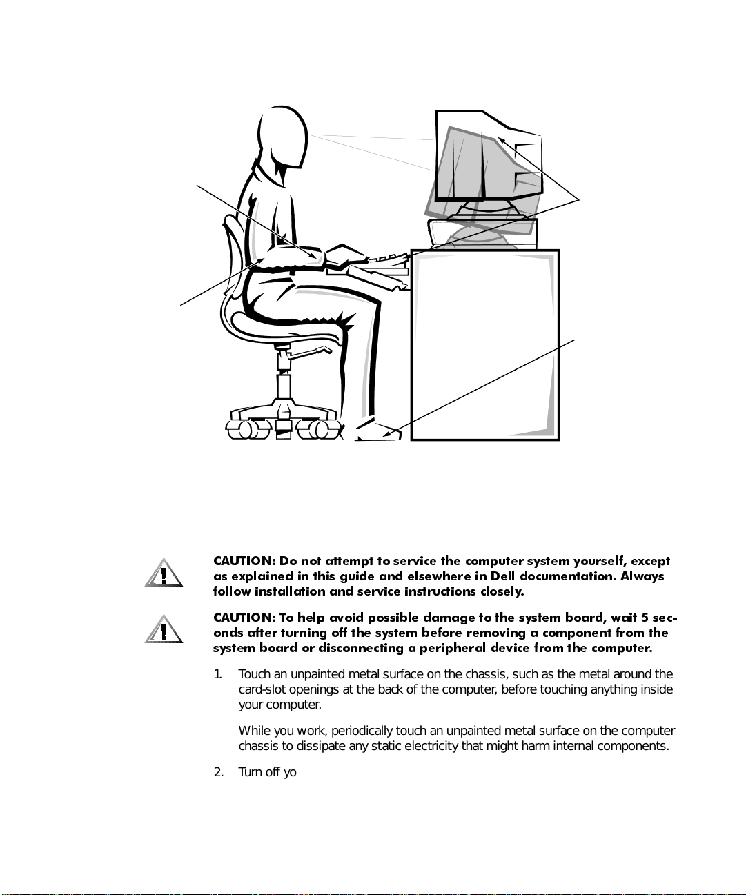
Posi tion y our s y stem so that the monitor and ke y board are directly in front of y ou
as you work. Specia l shelves are available (from Dell and other sources) to help
you correctly position your keyboard.
Set the monitor at a c omf o rtable vie w ing dis tance (us ually 510 to 610 millimeters
[20 to 24 inches] from your eyes).
Make sure the monitor screen is at eye level or slightly lower when you are sitting
in front of the monitor.
Adjust the tilt of the mo nitor, its contrast a nd bri ghtness settings, and the lighting
around you (such as overhead lights, desk lamps, and the curtains or blinds on
nearby windows) to minimize reflections and glare on the monitor screen.
Use a chair that provides good lower back support.
Keep your forearms horizontal with your wrists in a neutral, comfortable position
while using the keyboard or mouse.
Always leave space to rest your hands while using the keyboard or mous e.
Let your upper arms hang naturally at your sides.
Sit erect, with your feet resting on the floor and your thighs level.
When sitting, make sure the weight of your legs is on your feet and not on the
front of your chair seat. Adjust your chair’s height or use a footre st, if necessary,
to maintain proper posture.
Vary your work activities. Try to organize your work so that you do not have to
type for extended periods of time. When you stop typing, try to do things that
use both hands.
vi
Page 5
wrists relaxed and flat
arms at desk le vel
monitor screen at or below eye level
monitor and
keyboard
positioned
directly
in front of user
fee t flat on
the floor
:KHQ:RUNLQJ,QVLGH<RXU&RPSXWHU
Before you remove the computer cover, perform the following steps in the sequence
indicated.
&$87,21 'R QRW DWWHPSW WR VHUYLFH WKH FRPSXWHU V\VWHP \RXUVHOI H[FHSW
DV H[SODLQHG LQ WKLV JXLGH DQG HOVHZKHUH LQ 'HOO GRFXPHQWDWLRQ $OZD\V
IROORZ LQVWDOODWLRQ DQG VHUYLFH LQVWUXFWLRQV FORVHO\
&$87,21 7R KHOS DYRLG SRVVLEOH GDPDJH WR WKH V\VWHP ERDUG ZDLW VHF
RQGV DIWHU WXUQLQJ RII WKH V\VWHP EHIRUH UHPRYLQJ D FRPSRQHQW IURP WKH
V\VWHP ERDUG RU GLVFRQQHFWLQJ D SHULSKHUDO GHYLFH IURP WKH FRPSXWHU
1. Touch
2. Turn off your computer and any peripherals.
an unpainted metal surface on the chassis, such as the metal around the
card-slot openings at the back of the computer, before touching anything inside
your computer.
While you work, pe riodically touch an unpa inted metal surface on the computer
chassis to dissipate any static electricity that might harm internal components.
vii
Page 6

3. Disconnect your computer and peripherals from their power sources. Also, disconnect any telephone or telecommunication lines from the
computer.
Doing so reduces the potential for personal injury or shock.
In addition, take note of these safety guidelines when appropriate:
When you disco nnect a ca ble, pul l on it s conne ctor or on it s strain -relief loop , not
on the cable itself. Some cables have a connector with locking tabs; if you are disconnecting this type of cable, press in on the locking tabs before disconnecting
the cable. As you pull connectors apart, keep them evenly aligned to avoid bending any connector pins. Also, before you connect a cable, make sure both
connectors are correctly oriented and aligned.
Handle components and cards with care. Don’t touch the components or con-
tacts on a card. Hold a card by its edges or by its metal mounting br acket. Hold a
component such as a microprocessor chip by its edges, not by its pins.
:$51,1*
7KHUH LV D GDQJHU RI D QHZ EDWWHU\ H[SORGLQJ LI LW LV LQFRUUHFWO\ LQVWDOOHG
5HSODFH WKH EDWWHU\ RQO\ ZLWK WKH VDPH RU HTXLYDOHQW W\SH UHFRPPHQGHG
E\ WKH PDQXIDFWXUHU 'LVFDUG XVHG EDWWHULHV DFFRUGLQJ WR WKH PDQXIDF
WXUHU·V LQVWUXFWLRQV
3URWHFWLQJ$JDLQVW(OHFWURVWDWLF'LVFKDUJH
Static electricity can harm delicate components inside your computer. To prevent
static damage, discharge static electricity from your body before you touch any of
your computer’s electronic components, such as the microprocessor. You can do so
by touching an unpainted metal surface on the computer chassis.
As you continue to work inside the computer, periodically touch an unpainted metal
surface to remove any static charge your body may have accumulated.
You can also take the following steps to prevent damage from electrostatic discharge
(ESD):
When unpacking a static-sensitive component from its shipping carton, do not
remove the co mpone nt from the a ntistatic packing material until y ou are re ady to
install the component in your computer. Just before unwrapping the antistatic
packaging, be sure to discharge static electricity from your body.
When transporting a sensitive component, first place it in an antistatic container
or packaging.
Handle all sensitive components in a static-safe area. If possible, use antistatic
floor pads and workbench pads.
viii
Page 7

The following caution may appear throughout this document to remind you of these
precautions:
&$87,21 6HH ´3URWHFWLQJ $JDLQVW (OHFWURVWDWLF 'LVFKDUJHµ LQ WKH VDIHW\
LQVWUXFWLRQV DW WKH IURQW RI WKLV JXLGH
ix
Page 8

x
Page 9

3UHIDFH
$ERXW7KLV*XLGH
This guide is intended for anyone who uses the Dell Precision 210 desktop computer
systems. It can be us ed b y both fi rst-time and e xper ience d com puter users who w a nt
to learn about the f eat ures a nd operati on of the sy stem s or who w ant to u pgrade the ir
computers. The chapte rs and appendixes are summarized as follows:
Everyone should read Chapter 1, “Introduction,” for an overview of the system
features and information on where to get help if you need it.
Everyone should read the first few sections of Chapter 2, “Using the Software
Support Utilities,” to find out which utilities and drivers have been included with
the system. Only users who want to use one of the utilities or drivers need to
read the rest of Chapter 2.
Everyone should read the first several sections of Chapter 3, “Using the System
Setup Program,” to familiarize themselves with this important program. Only
users who want to make configuration changes to their system or who want to
use the password features need to read the rest of Chapter 3.
Users who add or remov e an Indus try-Standard Arc hitect ure (ISA) e xpansio n card
should read Chapter 4, “Using the ISA Configuration Utility.”
Users who want to connect their system to a network should read Chapter 5,
“Using the Network Interface Controller.” This chapter provides information on
connecting the system to a networ k, configuring the optional network interface
controller (NIC), and installing drivers for the NIC.
Users who need information on the integrated sound features of the computer
system should read Chapter 6, “Using the Integrated Audio Controller.”
Chapter 6 provide s informatio n on connectin g audio equipment to your comp uter ,
installing audio drivers, and reconfiguring the integrated audio controller.
Chapter 7, “Worki ng Inside Your Computer,” Chapter 8, “Installing System Bo ard
Options,” and Chapt er 9 , “In stalli ng Dri ves,” are intended for us ers wh o want to
install or remove options inside the computer, such as dual in-line memory modules (DIMMs), expansion cards, or drives.
xi
Page 10

Appendix A, “Technical Specifications,” and Appendix B, “Hardware Configura-
tion Features,” are intended primarily as reference material for users interested
in learning more abou t the de tails of the system. Users who add internal options
may need to refer to Appendix B to change jumper or switch settings.
Appendix C, “ISA Configuration Utility Messages,” describes error messages
generated by the ISA Configuration Utility (ICU), possible causes, and corrective
actions.
Appendix D, “Maintaining the System,” describes preventive maintenance pro-
cedures that you should perform regularly to keep your computer system in top
operating condition.
Appendix E, “Regulatory Notices,” is for users who are interested in which regu-
latory agencies have tested and approved the Dell Precision WorkStation 410
desktop systems.
Appendix F, “Warranties and Return Policy,” describes the warranty for your Dell
system and the “Total Satisfaction” Return Policy.
The Glossary provides definitions of terms, acronyms, and abbreviations used in
this guide.
:DUUDQW\DQG5HWXUQ3ROLF\,QIRUPDWLRQ
Dell Computer Corporation (“Dell”) manufactures its hardware products from parts
and components that are new or equivalent to new in accordance with industrystandard practices. For information about the Dell warranty for your system, see
Appendix F, “Warranties and Return Policy.”
xii
2WKHU'RFXPHQWV<RX0D\1HHG
Besides this
The
computer system.
The
and instructions for using the Dell Diagnostics
Video card documentation from the card manufacturer describes the video card
and video driv ers included with the system. Refer to this documentation for information about configuring and optimizing your video subsystem.
You may also have one or more of the following documents.
NOTE : Docume ntation updates are some times inc luded with you r sys tem to desc ribe
changes to your system or software. Always read these updates
any other documentation because the updates often contain the latest information.
Operating system documentation is included if you ordered your operating
system software from Dell. This documentation describes how to install (if necessary), configure, and use your operating system software.
User’s Guide
Getting Started
Diagnostics and Troubleshooting Guide
, the following documentation is included with your system:
sheet provides step-by-step instructions for setting up your
includes troubles hoo ting pro ced ure s
to test your computer system.
consulting
before
Page 11
Documentation is included with any options you purchase separately from your
system. T h is do cu men tation i nc ludes information that y o u ne ed to c onfigure and
install these options in your Dell computer. Installation instructions for the
options are included in this
the options.
User’s Guide
or in the documentation tha t ca me wi th
Technical information files—sometimes called “readme” files—may be installed
on your hard-di sk dri v e to pro vid e las t-minute update s abou t technical ch anges to
your system or advanced technical reference material intended for experienced
users or technicians.
1RWDWLRQDO&RQYHQWLRQV
The following subsections describe notational conventions used in this document.
:DUQLQJV&DXWLRQV1RWHV
Throughout this g uide, there may be bloc k s of te xt printed i n bold type or i n italic type.
These blocks are warnings, cautions, and notes, and they are used as follows:
:$51,1* $ :$51,1* LQGLFDWHV WKH SRWHQWLDO IRU ERGLO\ KDUP DQG WHOOV
\RX KRZ WR DYRLG WKH SUREOHP
&$87,21 $ &$87,21 LQGLFDWHV HLWKHU SRWHQWLDO GDPDJH WR KDUGZDUH RU
ORVV RI GDWD DQG WHOOV \RX KRZ WR DYRLG WKH SUREOHP
NOTE: A NOTE indicates important information that helps you make better use of
your computer system.
7\SRJUDSKLFDO&RQYHQWLRQV
The following list defines (where appropriate) and illu strates typographical conventions used as visual cues for specific elements of text throughout this document:
Interface components
and selections, and other options that appear on the monitor screen or display.
They are presented in bold.
Example: Click OK.
Keycaps
angle brackets.
Example: <Enter>
Key com bi nations
wise indicated) to perform a single function.
Example: <
are labels that appear on the keys on a keyboard. They are enclosed in
Ctrl><Alt><Enter
are window titles, button and icon names, menu names
are series of keys to be pressed simultaneously (unless other-
>
xiii
Page 12

Commands
not intended to be typed whe n referenced.
Example: “Use the format command to . . . .”
In contrast, commands presented in the Courier New font are part of an instruction and intended to be typed.
Example: “Type format a: to format the diskette in drive A.”
presented in lowercase bold are for refe ren ce pu rpos es onl y an d are
Filenames
Examples: aut o exec.bat and c:\win do ws
Syntax lines
are presented in lowercase bold; variable parameters (those for which you substitute a value) are p resented in lowercase italics; constant parameters are
presented in lowercase bold. The brackets indicate items that are optional.
Example: del [
Command lines
mand’s possible parameters. Command lines are presented in the Courier New
font.
Example: del c :\myfil e.doc
Screen text
mand (referred to as a
New font.
Example: The following message appears on your screen:
No boot device available
Example: “Type md c:\programs and press <
Variables
italics.
Example: DIMM_x (where x represents the DIMM socket designation).
directory names
and
consist of a command and all its possible parameters. Commands
drive
path] filename
:] [
consist of a command and may include one or more of the com-
is a message or text that you are instructed to type as part of a com-
command line
are placeholders for which you substitu te a val ue. Th ey are presente d in
are presen ted in lowercase bold.
[/p]
). Screen text is presented in the Courier
>.”
Enter
xiv
Page 13

&RQWHQWV
&KDSWHU ,QWURGXFWLRQ
System Features. . . . . . . . . . . . . . . . . . . . . . . . . . . . . . . . . . . . . . . . . . . . . . . . . . . 1-1
Dell OpenManage Program. . . . . . . . . . . . . . . . . . . . . . . . . . . . . . . . . . . . . . . . . . . 1-4
Fault Management. . . . . . . . . . . . . . . . . . . . . . . . . . . . . . . . . . . . . . . . . . . . . . 1-5
Configuration Management . . . . . . . . . . . . . . . . . . . . . . . . . . . . . . . . . . . . . . . 1-6
Asset Management . . . . . . . . . . . . . . . . . . . . . . . . . . . . . . . . . . . . . . . . . . . . . 1-6
Security Management . . . . . . . . . . . . . . . . . . . . . . . . . . . . . . . . . . . . . . . . . . . 1-6
PXE. . . . . . . . . . . . . . . . . . . . . . . . . . . . . . . . . . . . . . . . . . . . . . . . . . . . . . . . . . 1-7
Wakeup On LAN . . . . . . . . . . . . . . . . . . . . . . . . . . . . . . . . . . . . . . . . . . . . . . . 1-7
Auto Power On. . . . . . . . . . . . . . . . . . . . . . . . . . . . . . . . . . . . . . . . . . . . . . . . . 1-7
Important Note to Windows 95, Windows 98, and Windows NT 4.0 Users . . . . . 1-8
Reinstalling Windows NT 4.0 . . . . . . . . . . . . . . . . . . . . . . . . . . . . . . . . . . . . . . 1-8
Reinstalling Windows 95 or Windows 98 . . . . . . . . . . . . . . . . . . . . . . . . . . . . 1-8
Intel PIIX4 INF Update Installer for Windows 95 or Windows 98. . . . . . . 1-9
Front Panel . . . . . . . . . . . . . . . . . . . . . . . . . . . . . . . . . . . . . . . . . . . . . . . . . . . . . . 1-11
Back Panel. . . . . . . . . . . . . . . . . . . . . . . . . . . . . . . . . . . . . . . . . . . . . . . . . . . . . . . 1-12
Connecting External Devices . . . . . . . . . . . . . . . . . . . . . . . . . . . . . . . . . . . . . 1-12
Security Cable Slot and Padlock Ring. . . . . . . . . . . . . . . . . . . . . . . . . . . . . . . 1-12
Getting Help . . . . . . . . . . . . . . . . . . . . . . . . . . . . . . . . . . . . . . . . . . . . . . . . . . . . . 1-13
&KDSWHU 8VLQJWKH6RIWZDUH6XSSRUW8WLOLWLHV
Dell-Installed Software Support Utilities . . . . . . . . . . . . . . . . . . . . . . . . . . . . . . . . 2-2
Backing Up the Software Support Utilities . . . . . . . . . . . . . . . . . . . . . . . . . . . . . . . 2-2
Software Support Utilities on Diskette . . . . . . . . . . . . . . . . . . . . . . . . . . . . . . . . . . 2-2
System Utilities and Services . . . . . . . . . . . . . . . . . . . . . . . . . . . . . . . . . . . . . . . . . 2-2
Reinstalling the Dell System Utilities and Services for Windows 95
or Windows 98. . . . . . . . . . . . . . . . . . . . . . . . . . . . . . . . . . . . . . . . . . . . . . . . . 2-3
Reinstalling the Dell System Utilities and Services for Windows NT 4.0. . . . . 2-3
Removing a Service . . . . . . . . . . . . . . . . . . . . . . . . . . . . . . . . . . . . . . . . . . . . . 2-4
Asset Tag Utility. . . . . . . . . . . . . . . . . . . . . . . . . . . . . . . . . . . . . . . . . . . . . . . . 2-4
xv
Page 14

Assigning and Deleting an Asset Tag Number . . . . . . . . . . . . . . . . . . . . . 2-5
Assigning and Deleting an Owner Tag . . . . . . . . . . . . . . . . . . . . . . . . . . . 2-5
Dell AutoShutdown Service . . . . . . . . . . . . . . . . . . . . . . . . . . . . . . . . . . . . . . 2-5
How the AutoShutdown Service Works . . . . . . . . . . . . . . . . . . . . . . . . . . 2-6
If Your Operating System Locks Up . . . . . . . . . . . . . . . . . . . . . . . . . . . . . 2-6
Dell ThermalShutdown Service . . . . . . . . . . . . . . . . . . . . . . . . . . . . . . . . . . . . 2-6
Auto Power On Utility . . . . . . . . . . . . . . . . . . . . . . . . . . . . . . . . . . . . . . . . . . . 2-7
Installing the Auto Power On Utility . . . . . . . . . . . . . . . . . . . . . . . . . . . . . 2-7
Bus-Mastering EIDE Drivers . . . . . . . . . . . . . . . . . . . . . . . . . . . . . . . . . . . . . . . . . . 2-8
Enabling the Windows 95 or Windows 98 Bus-Mastering EIDE Driver. . . . . . 2-8
Microsoft Updated ATAPI Drivers . . . . . . . . . . . . . . . . . . . . . . . . . . . . . . . . . . . . . 2-8
Reinstalling the Windows NT 4.0 Microsoft Updated ATAPI Driver . . . . . . . . 2-9
Removing the Windows NT 4.0 Microsoft Updated ATAPI Driver. . . . . . . . . . 2-9
&KDSWHU 8VLQJWKH6\VWHP6HWXS3URJUDP
Entering the System Setup Program. . . . . . . . . . . . . . . . . . . . . . . . . . . . . . . . . . . . 3-2
System Setup Screens . . . . . . . . . . . . . . . . . . . . . . . . . . . . . . . . . . . . . . . . . . . . . . 3-2
Using the System Setup Program. . . . . . . . . . . . . . . . . . . . . . . . . . . . . . . . . . . . . . 3-4
System Setup Options . . . . . . . . . . . . . . . . . . . . . . . . . . . . . . . . . . . . . . . . . . . . . . 3-6
Time . . . . . . . . . . . . . . . . . . . . . . . . . . . . . . . . . . . . . . . . . . . . . . . . . . . . . . . . . 3-6
Date . . . . . . . . . . . . . . . . . . . . . . . . . . . . . . . . . . . . . . . . . . . . . . . . . . . . . . . . . 3-6
Diskette Drive A and Diskette Drive B . . . . . . . . . . . . . . . . . . . . . . . . . . . . . . . 3-6
Drives: Primary and Secondary . . . . . . . . . . . . . . . . . . . . . . . . . . . . . . . . . . . . 3-7
EIDE Devices Other Than Hard-Disk Drives . . . . . . . . . . . . . . . . . . . . . . . 3-7
EIDE Hard-Disk Drives . . . . . . . . . . . . . . . . . . . . . . . . . . . . . . . . . . . . . . . 3-7
If You Have a Problem . . . . . . . . . . . . . . . . . . . . . . . . . . . . . . . . . . . . . . . 3-8
Reserved Memory . . . . . . . . . . . . . . . . . . . . . . . . . . . . . . . . . . . . . . . . . . . . . . 3-9
CPU Speed. . . . . . . . . . . . . . . . . . . . . . . . . . . . . . . . . . . . . . . . . . . . . . . . . . . . 3-9
Num Lock . . . . . . . . . . . . . . . . . . . . . . . . . . . . . . . . . . . . . . . . . . . . . . . . . . . . 3-9
Chassis Intrusion . . . . . . . . . . . . . . . . . . . . . . . . . . . . . . . . . . . . . . . . . . . . . . . 3-9
Thermal Power-Off. . . . . . . . . . . . . . . . . . . . . . . . . . . . . . . . . . . . . . . . . . . . . 3-10
Video DAC Snoop . . . . . . . . . . . . . . . . . . . . . . . . . . . . . . . . . . . . . . . . . . . . . 3-10
Keyboard Errors . . . . . . . . . . . . . . . . . . . . . . . . . . . . . . . . . . . . . . . . . . . . . . . 3-10
System Password . . . . . . . . . . . . . . . . . . . . . . . . . . . . . . . . . . . . . . . . . . . . . 3-10
Password Status . . . . . . . . . . . . . . . . . . . . . . . . . . . . . . . . . . . . . . . . . . . . . . 3-11
Using Password Status With a System Password Enabled . . . . . . . . . . 3-11
Using Password Status Without a System Password Enabled. . . . . . . . 3-11
Boot Sequence . . . . . . . . . . . . . . . . . . . . . . . . . . . . . . . . . . . . . . . . . . . . . . . 3-12
Diskette First. . . . . . . . . . . . . . . . . . . . . . . . . . . . . . . . . . . . . . . . . . . . . . 3-12
Hard Disk Only . . . . . . . . . . . . . . . . . . . . . . . . . . . . . . . . . . . . . . . . . . . . 3-12
CD-ROM First . . . . . . . . . . . . . . . . . . . . . . . . . . . . . . . . . . . . . . . . . . . . . 3-12
Device List . . . . . . . . . . . . . . . . . . . . . . . . . . . . . . . . . . . . . . . . . . . . . . . 3-12
xvi
Page 15

Setup Password . . . . . . . . . . . . . . . . . . . . . . . . . . . . . . . . . . . . . . . . . . . . . 3-14
Auto Power On . . . . . . . . . . . . . . . . . . . . . . . . . . . . . . . . . . . . . . . . . . . . . . . 3-14
Power Management . . . . . . . . . . . . . . . . . . . . . . . . . . . . . . . . . . . . . . . . . . . 3-14
Saving Monitor Power. . . . . . . . . . . . . . . . . . . . . . . . . . . . . . . . . . . . . . . 3-14
Saving EIDE Hard-Disk Drive Power . . . . . . . . . . . . . . . . . . . . . . . . . . . . 3-15
Wakeup On LAN . . . . . . . . . . . . . . . . . . . . . . . . . . . . . . . . . . . . . . . . . . . . . . 3-16
Sound. . . . . . . . . . . . . . . . . . . . . . . . . . . . . . . . . . . . . . . . . . . . . . . . . . . . . . . 3-16
NIC . . . . . . . . . . . . . . . . . . . . . . . . . . . . . . . . . . . . . . . . . . . . . . . . . . . . . . . . 3-16
Mouse . . . . . . . . . . . . . . . . . . . . . . . . . . . . . . . . . . . . . . . . . . . . . . . . . . . . . . 3-16
Serial Port 1 and Serial Port 2 . . . . . . . . . . . . . . . . . . . . . . . . . . . . . . . . . . . . 3-17
Parallel Port . . . . . . . . . . . . . . . . . . . . . . . . . . . . . . . . . . . . . . . . . . . . . . . . . 3-17
Parallel Mode . . . . . . . . . . . . . . . . . . . . . . . . . . . . . . . . . . . . . . . . . . . . . . . . . 3-17
IDE Hard Disk . . . . . . . . . . . . . . . . . . . . . . . . . . . . . . . . . . . . . . . . . . . . . . . . 3-17
Diskette . . . . . . . . . . . . . . . . . . . . . . . . . . . . . . . . . . . . . . . . . . . . . . . . . . . . . 3-18
Speaker . . . . . . . . . . . . . . . . . . . . . . . . . . . . . . . . . . . . . . . . . . . . . . . . . . . . . 3-18
System Data. . . . . . . . . . . . . . . . . . . . . . . . . . . . . . . . . . . . . . . . . . . . . . . . . . 3-19
Using the System Password Feature . . . . . . . . . . . . . . . . . . . . . . . . . . . . . . . . . . 3-19
Assigning a System Password. . . . . . . . . . . . . . . . . . . . . . . . . . . . . . . . . . . . 3-20
Using Your System Password to Secure Your System . . . . . . . . . . . . . . . . . 3-21
Deleting or Changing an Existing System Password . . . . . . . . . . . . . . . . . . 3-22
Using the Setup Password Feature. . . . . . . . . . . . . . . . . . . . . . . . . . . . . . . . . . . . 3-23
Assigning a Setup Password . . . . . . . . . . . . . . . . . . . . . . . . . . . . . . . . . . . . . 3-23
Operating With a Setup Password Enabled. . . . . . . . . . . . . . . . . . . . . . . . . . 3-23
Deleting or Changing an Existing Setup Password . . . . . . . . . . . . . . . . . . . . 3-24
Disabling a Forgotten Password . . . . . . . . . . . . . . . . . . . . . . . . . . . . . . . . . . . . . . 3-24
Responding to Error Messages . . . . . . . . . . . . . . . . . . . . . . . . . . . . . . . . . . . . . . 3-25
&KDSWHU 8VLQJWKH,6$&RQILJXUDWLRQ8WLOLW\
Quick Start . . . . . . . . . . . . . . . . . . . . . . . . . . . . . . . . . . . . . . . . . . . . . . . . . . . . . . . 4-2
About the ICU . . . . . . . . . . . . . . . . . . . . . . . . . . . . . . . . . . . . . . . . . . . . . . . . . . . . . 4-3
ICU Database. . . . . . . . . . . . . . . . . . . . . . . . . . . . . . . . . . . . . . . . . . . . . . . . . . 4-3
When to Run the ICU . . . . . . . . . . . . . . . . . . . . . . . . . . . . . . . . . . . . . . . . . . . . . . . 4-3
Preparing to Use the ICU. . . . . . . . . . . . . . . . . . . . . . . . . . . . . . . . . . . . . . . . . . . . . 4-4
Backing Up the ICU Diskette . . . . . . . . . . . . . . . . . . . . . . . . . . . . . . . . . . . . . . 4-4
Starting the ICU. . . . . . . . . . . . . . . . . . . . . . . . . . . . . . . . . . . . . . . . . . . . . . . . . . . . 4-5
Accessing Help. . . . . . . . . . . . . . . . . . . . . . . . . . . . . . . . . . . . . . . . . . . . . . . . . 4-5
Making Selections in the ICU. . . . . . . . . . . . . . . . . . . . . . . . . . . . . . . . . . . . . . 4-5
Adding a Listed Card. . . . . . . . . . . . . . . . . . . . . . . . . . . . . . . . . . . . . . . . . . . . . . . . 4-6
Adding an Unlisted Card . . . . . . . . . . . . . . . . . . . . . . . . . . . . . . . . . . . . . . . . . . . . . 4-9
Modifying a Card. . . . . . . . . . . . . . . . . . . . . . . . . . . . . . . . . . . . . . . . . . . . . . . . . . 4-11
Removing a Card . . . . . . . . . . . . . . . . . . . . . . . . . . . . . . . . . . . . . . . . . . . 4-13
Viewing Resources . . . . . . . . . . . . . . . . . . . . . . . . . . . . . . . . . . . . . . . . . . . . . . . . 4-13
xvii
Page 16

Saving the System Configuration . . . . . . . . . . . . . . . . . . . . . . . . . . . . . . . . . . . . . 4-14
Exiting the ICU. . . . . . . . . . . . . . . . . . . . . . . . . . . . . . . . . . . . . . . . . . . . . . . . . . . . 4-14
Locking and Unlocking Cards . . . . . . . . . . . . . . . . . . . . . . . . . . . . . . . . . . . . . . . . 4-14
Locking and Unlocking All Resources . . . . . . . . . . . . . . . . . . . . . . . . . . . . . . 4-15
Locking and Unlocking Configuration Resources. . . . . . . . . . . . . . . . . . . . . . 4-15
&KDSWHU 8VLQJWKH1HWZRUN,QWHUIDFH&RQWUROOHU
Connecting to a Network . . . . . . . . . . . . . . . . . . . . . . . . . . . . . . . . . . . . . . . . . . . . 5-2
Network Cable Requirements . . . . . . . . . . . . . . . . . . . . . . . . . . . . . . . . . . . . . 5-3
Setting the Network Frame Type for Windows 95 . . . . . . . . . . . . . . . . . . . . . 5-3
Configuring the NIC . . . . . . . . . . . . . . . . . . . . . . . . . . . . . . . . . . . . . . . . . . . . . . . . 5-4
Windows NT 4.0 NIC Driver . . . . . . . . . . . . . . . . . . . . . . . . . . . . . . . . . . . . . . 5-4
Windows 95 NIC Driver . . . . . . . . . . . . . . . . . . . . . . . . . . . . . . . . . . . . . . . . . . 5-5
Dell-Installed Windows 95 Service Release 2.1 . . . . . . . . . . . . . . . . . . . . 5-5
Windows 95 Operating Systems Not Installed by Dell. . . . . . . . . . . . . . . 5-7
Using the NDIS 2.01 Driver With Windows 95. . . . . . . . . . . . . . . . . . . . . 5-9
Using 3Com EtherDisk XL Version 3.01 Diskettes . . . . . . . . . . . . . . . . . . 5-9
Windows 98 NIC Driver . . . . . . . . . . . . . . . . . . . . . . . . . . . . . . . . . . . . . . . . . . 5-9
Reinstalling the NIC Driver for a New Windows 98 Installation . . . . . . . . 5-9
Reinstalling the NIC Driver for an Existing Windows 98 Installation. . . . 5-11
&KDSWHU 8VLQJWKH,QWHJUDWHG$XGLR&RQWUROOHU
Connecting Audio Devices . . . . . . . . . . . . . . . . . . . . . . . . . . . . . . . . . . . . . . . . . . . 6-1
Speakers. . . . . . . . . . . . . . . . . . . . . . . . . . . . . . . . . . . . . . . . . . . . . . . . . . . . . . 6-2
Microphones . . . . . . . . . . . . . . . . . . . . . . . . . . . . . . . . . . . . . . . . . . . . . . . . . . 6-2
Record/Playback Devices . . . . . . . . . . . . . . . . . . . . . . . . . . . . . . . . . . . . . . . . . 6-2
CD-ROM Drives . . . . . . . . . . . . . . . . . . . . . . . . . . . . . . . . . . . . . . . . . . . . . . . . 6-2
Adjusting Volume . . . . . . . . . . . . . . . . . . . . . . . . . . . . . . . . . . . . . . . . . . . . . . . . . . 6-3
Adjusting Volume in Windows 95 . . . . . . . . . . . . . . . . . . . . . . . . . . . . . . . . . . 6-3
Adjusting Volume in Windows 98 . . . . . . . . . . . . . . . . . . . . . . . . . . . . . . . . . . 6-3
Adjusting Volume in Windows NT 4.0 . . . . . . . . . . . . . . . . . . . . . . . . . . . . . . . 6-4
Muting the Internal Speaker . . . . . . . . . . . . . . . . . . . . . . . . . . . . . . . . . . . . . . 6-4
Adjusting 3D Sound. . . . . . . . . . . . . . . . . . . . . . . . . . . . . . . . . . . . . . . . . . . . . . . . . 6-4
Using Audio Utilities . . . . . . . . . . . . . . . . . . . . . . . . . . . . . . . . . . . . . . . . . . . . . . . . 6-5
Installing Audio Drivers . . . . . . . . . . . . . . . . . . . . . . . . . . . . . . . . . . . . . . . . . . . . . . 6-5
Audio Drivers for Windows 95 . . . . . . . . . . . . . . . . . . . . . . . . . . . . . . . . . . . . . 6-5
Audio Drivers for Windows 98. . . . . . . . . . . . . . . . . . . . . . . . . . . . . . . . . . . . . 6-6
Audio Drivers for Windows NT 4.0. . . . . . . . . . . . . . . . . . . . . . . . . . . . . . . . . . 6-7
xviii
Page 17

&KDSWHU :RUNLQJ,QVLGH<RXU&RPSXWHU
Before You Begin . . . . . . . . . . . . . . . . . . . . . . . . . . . . . . . . . . . . . . . . . . . . . . . . . . 7-1
Safety First—For You and Your Computer. . . . . . . . . . . . . . . . . . . . . . . . . . . . 7-1
Unpacking Your Hardware Option . . . . . . . . . . . . . . . . . . . . . . . . . . . . . . . . . . 7-2
Removing the Computer Cover. . . . . . . . . . . . . . . . . . . . . . . . . . . . . . . . . . . . . . . . 7-2
Replacing the Computer Cover . . . . . . . . . . . . . . . . . . . . . . . . . . . . . . . . . . . . . . . . 7-4
Inside Your Computer . . . . . . . . . . . . . . . . . . . . . . . . . . . . . . . . . . . . . . . . . . . . . . . 7-5
Rotating the Power Supply Away From the System Board. . . . . . . . . . . . . . . . . . . 7-7
&KDSWHU ,QVWDOOLQJ6\VWHP%RDUG2SWLRQV
Expansion Cards . . . . . . . . . . . . . . . . . . . . . . . . . . . . . . . . . . . . . . . . . . . . . . . . . . . 8-2
Expansion Slots . . . . . . . . . . . . . . . . . . . . . . . . . . . . . . . . . . . . . . . . . . . . . . . . 8-3
Installing an Expansion Card . . . . . . . . . . . . . . . . . . . . . . . . . . . . . . . . . . . . 8-4
Removing an Expansion Card . . . . . . . . . . . . . . . . . . . . . . . . . . . . . . . . . . . . . 8-6
Adding Memory. . . . . . . . . . . . . . . . . . . . . . . . . . . . . . . . . . . . . . . . . . . . . . . . . . . . 8-7
DIMM Installation Guidelines. . . . . . . . . . . . . . . . . . . . . . . . . . . . . . . . . . . . . . 8-7
Installing a DIMM . . . . . . . . . . . . . . . . . . . . . . . . . . . . . . . . . . . . . . . . . . . 8-9
Removing a DIMM . . . . . . . . . . . . . . . . . . . . . . . . . . . . . . . . . . . . . . . . . 8-10
Microprocessor Upgrades . . . . . . . . . . . . . . . . . . . . . . . . . . . . . . . . . . . . . . . . . . . 8-10
Adding or Replacing a Microprocessor. . . . . . . . . . . . . . . . . . . . . . . . . . . . . . 8-10
Replacing the System Battery. . . . . . . . . . . . . . . . . . . . . . . . . . . . . . . . . . . . . . . . 8-13
&KDSWHU ,QVWDOOLQJ'ULYHV
Removing and Replacing Front-Panel Inserts . . . . . . . . . . . . . . . . . . . . . . . . . . 9-2
Connecting Drives . . . . . . . . . . . . . . . . . . . . . . . . . . . . . . . . . . . . . . . . . . . . . . . . 9-3
Installing a Drive in a 5.25-Inch Drive Bay . . . . . . . . . . . . . . . . . . . . . . . . . . . . . . . . 9-5
Installing an EIDE Hard-Disk Drive. . . . . . . . . . . . . . . . . . . . . . . . . . . . . . . . . . . . . 9-10
EIDE Drive Addressing . . . . . . . . . . . . . . . . . . . . . . . . . . . . . . . . . . . . . . . . . . 9-10
Installing an EIDE Hard-Disk Drive in the Hard-Disk Drive Bracket . . . . . . . . 9-10
Partitioning and Logically Formatting Your EIDE Hard-Disk Drive 9-14
$SSHQGL[$ 7HFKQLFDO6SHFLILFDWLRQV $
$SSHQGL[% +DUGZDUH&RQILJXUDWLRQ)HDWXUHV %
Jumpers and Switches—A General Explanation. . . . . . . . . . . . . . . . . . . . . . . . . . . B-1
Jumpers . . . . . . . . . . . . . . . . . . . . . . . . . . . . . . . . . . . . . . . . . . . . . . . . . . . . . . B-1
Switches. . . . . . . . . . . . . . . . . . . . . . . . . . . . . . . . . . . . . . . . . . . . . . . . . . . . . . B-2
System Board Labels. . . . . . . . . . . . . . . . . . . . . . . . . . . . . . . . . . . . . . . . . . . . . . . . B-5
I/O Ports and Connectors . . . . . . . . . . . . . . . . . . . . . . . . . . . . . . . . . . . . . . . . . . . .B-6
Serial and Parallel Ports . . . . . . . . . . . . . . . . . . . . . . . . . . . . . . . . . . . . . . . . . . B-6
Adding an Expansion Card Containing Serial or Parallel Ports. . . . . . . . . . B-7
xix
Page 18

Serial Port Connectors . . . . . . . . . . . . . . . . . . . . . . . . . . . . . . . . . . . . . . . B-8
Parallel Port Connector . . . . . . . . . . . . . . . . . . . . . . . . . . . . . . . . . . . . . . . B-9
Keyboard and Mouse Connectors . . . . . . . . . . . . . . . . . . . . . . . . . . . . . . . . . B-10
Keyboard Connector . . . . . . . . . . . . . . . . . . . . . . . . . . . . . . . . . . . . . . . . B-10
Mouse Connector. . . . . . . . . . . . . . . . . . . . . . . . . . . . . . . . . . . . . . . . . . B-11
Video Connector. . . . . . . . . . . . . . . . . . . . . . . . . . . . . . . . . . . . . . . . . . . . . . . B-12
NIC Connector . . . . . . . . . . . . . . . . . . . . . . . . . . . . . . . . . . . . . . . . . . . . . . . . B-12
USB Connectors . . . . . . . . . . . . . . . . . . . . . . . . . . . . . . . . . . . . . . . . . . . . . . B-12
Microphone Jack . . . . . . . . . . . . . . . . . . . . . . . . . . . . . . . . . . . . . . . . . . . . . B-13
Line-Out Jack. . . . . . . . . . . . . . . . . . . . . . . . . . . . . . . . . . . . . . . . . . . . . . . . . B-14
Line-In Jack . . . . . . . . . . . . . . . . . . . . . . . . . . . . . . . . . . . . . . . . . . . . . . . . . . B-14
Interrupt Assignments. . . . . . . . . . . . . . . . . . . . . . . . . . . . . . . . . . . . . . . . . . . . . . B-14
Memory Allocations. . . . . . . . . . . . . . . . . . . . . . . . . . . . . . . . . . . . . . . . . . . . . . . . B-16
$SSHQGL[& ,6$&RQILJXUDWLRQ8WLOLW\0HVVDJHV &
ICU Error Messages . . . . . . . . . . . . . . . . . . . . . . . . . . . . . . . . . . . . . . . . . . . . . . . .C-1
Configuration Manager Messages . . . . . . . . . . . . . . . . . . . . . . . . . . . . . . . . . . . . . C-7
$SSHQGL[' 0DLQWDLQLQJWKH6\VWHP '
Data Preservation . . . . . . . . . . . . . . . . . . . . . . . . . . . . . . . . . . . . . . . . . . . . . . . . . . D-1
Scheduling Backups. . . . . . . . . . . . . . . . . . . . . . . . . . . . . . . . . . . . . . . . . . . . . D-1
Backup Devices . . . . . . . . . . . . . . . . . . . . . . . . . . . . . . . . . . . . . . . . . . . . . . . .D-1
Recovering Data. . . . . . . . . . . . . . . . . . . . . . . . . . . . . . . . . . . . . . . . . . . . . . . . D-2
Cleaning System Components . . . . . . . . . . . . . . . . . . . . . . . . . . . . . . . . . . . . . . . . D-2
Recommended Tools and Accessories . . . . . . . . . . . . . . . . . . . . . . . . . . . . . . D-3
Cleaning the System, Monitor, and Keyboard Exteriors. . . . . . . . . . . . . . . . . . D-3
Cleaning Drives . . . . . . . . . . . . . . . . . . . . . . . . . . . . . . . . . . . . . . . . . . . . . . . .D-4
Environmental Factors. . . . . . . . . . . . . . . . . . . . . . . . . . . . . . . . . . . . . . . . . . . . . . . D-4
Temperature. . . . . . . . . . . . . . . . . . . . . . . . . . . . . . . . . . . . . . . . . . . . . . . . . . .D-4
Humidity. . . . . . . . . . . . . . . . . . . . . . . . . . . . . . . . . . . . . . . . . . . . . . . . . . . . . . D-5
Altitude. . . . . . . . . . . . . . . . . . . . . . . . . . . . . . . . . . . . . . . . . . . . . . . . . . . . . . . D-5
Dust and Particles . . . . . . . . . . . . . . . . . . . . . . . . . . . . . . . . . . . . . . . . . . . . . .D-5
Corrosion . . . . . . . . . . . . . . . . . . . . . . . . . . . . . . . . . . . . . . . . . . . . . . . . . . . . . D-6
ESD . . . . . . . . . . . . . . . . . . . . . . . . . . . . . . . . . . . . . . . . . . . . . . . . . . . . . . . . . D-6
Electromagnetic and Radio Frequency Interference . . . . . . . . . . . . . . . .D-6
Magnetism. . . . . . . . . . . . . . . . . . . . . . . . . . . . . . . . . . . . . . . . . . . . . . . . . . . . D-7
Shock and Vibration . . . . . . . . . . . . . . . . . . . . . . . . . . . . . . . . . . . . . . . . . . . . .D-7
Power Source Interruptions. . . . . . . . . . . . . . . . . . . . . . . . . . . . . . . . . . . . . . . D-8
Power Protection Devices. . . . . . . . . . . . . . . . . . . . . . . . . . . . . . . . . . . . . . . . . . . . D-8
Surge Protectors . . . . . . . . . . . . . . . . . . . . . . . . . . . . . . . . . . . . . . . . . . . . . . .D-9
Line Conditioners. . . . . . . . . . . . . . . . . . . . . . . . . . . . . . . . . . . . . . . . . . . . . . .D-9
Uninterruptible Power Supplies . . . . . . . . . . . . . . . . . . . . . . . . . . . . . . . . . . . . D-9
xx
Page 19

$SSHQGL[( 5HJXODWRU\1RWLFHV(
FCC Notices (U.S. Only) . . . . . . . . . . . . . . . . . . . . . . . . . . . . . . . . . . . . . . . . . . . . . E-2
Class A. . . . . . . . . . . . . . . . . . . . . . . . . . . . . . . . . . . . . . . . . . . . . . . . . . . . . . . E-3
Class B. . . . . . . . . . . . . . . . . . . . . . . . . . . . . . . . . . . . . . . . . . . . . . . . . . . . . . . E-3
IC Notice (Canada Only). . . . . . . . . . . . . . . . . . . . . . . . . . . . . . . . . . . . . . . . . . . . . . E-4
CE Notice (European Union) . . . . . . . . . . . . . . . . . . . . . . . . . . . . . . . . . . . . . . . . . . E-4
EN 55022 Compliance (Czech Republic Only). . . . . . . . . . . . . . . . . . . . . . . . . . . . . E-5
VCCI Notice (Japan Only) . . . . . . . . . . . . . . . . . . . . . . . . . . . . . . . . . . . . . . . . . . . . E-5
Class A ITE. . . . . . . . . . . . . . . . . . . . . . . . . . . . . . . . . . . . . . . . . . . . . . . . . . . . E-5
Class B ITE. . . . . . . . . . . . . . . . . . . . . . . . . . . . . . . . . . . . . . . . . . . . . . . . . . . . E-6
Polish Center for Testing and Certification Notice. . . . . . . . . . . . . . . . . . . . . . . . . . E-6
Wymagania Polskiego Centrum BadaÒ i Certyfikacji . . . . . . . . . . . . . . . . . . . . . . . E-7
PozostaŠe instrukcje bezpieczeÒstwa . . . . . . . . . . . . . . . . . . . . . . . . . . . . . . . . . . E-7
NOM Information (Mexico Only) . . . . . . . . . . . . . . . . . . . . . . . . . . . . . . . . . . . . . . . E-8
Información para NOM
(únicamente para México) . . . . . . . . . . . . . . . . . . . . . . . . . . . . . . . . . . . . . . . . . . . . E-9
BCIQ Notice (Taiwan Only) . . . . . . . . . . . . . . . . . . . . . . . . . . . . . . . . . . . . . . . . . . . E-9
$SSHQGL[) :DUUDQW\5HWXUQ3ROLF\DQG<HDU6WDWHPHQWRI&RPSOLDQFH
)
Limited Three-Year Warranty (U.S. and Canada Only). . . . . . . . . . . . . . . . . . . . . . . F-1
Coverage During Year One. . . . . . . . . . . . . . . . . . . . . . . . . . . . . . . . . . . . . . . . F-1
Coverage During Years Two and Three . . . . . . . . . . . . . . . . . . . . . . . . . . . . . . F-2
General Provisions . . . . . . . . . . . . . . . . . . . . . . . . . . . . . . . . . . . . . . . . . . . . . . F-2
“Total Satisfaction” Return Policy (U.S. and Canada Only). . . . . . . . . . . . . . . . . . . F-3
Year 2000 Statement of Compliance for Dell-Branded Hardware Products . . . . . . F-4
Previous Products . . . . . . . . . . . . . . . . . . . . . . . . . . . . . . . . . . . . . . . . . . . . . . F-4
Software. . . . . . . . . . . . . . . . . . . . . . . . . . . . . . . . . . . . . . . . . . . . . . . . . . . . . . F-5
Additional Information . . . . . . . . . . . . . . . . . . . . . . . . . . . . . . . . . . . . . . . . . . . F-5
*ORVVDU\
,QGH[
)LJXUHV Figure 1-1. Dell OpenManage Program. . . . . . . . . . . . . . . . . . . . . . . . . . . . . . . . 1-5
Figure 1-2. Front Panel. . . . . . . . . . . . . . . . . . . . . . . . . . . . . . . . . . . . . . . . . . . . 1-11
Figure 1-3. Security Cable Slot and Padlock Ring . . . . . . . . . . . . . . . . . . . . . . . 1-13
Figure 3-1. System Setup Screens . . . . . . . . . . . . . . . . . . . . . . . . . . . . . . . . . . . 3-5
Figure 3-2. Sample Device List Screen . . . . . . . . . . . . . . . . . . . . . . . . . . . . . . . 3-13
Figure 4-1. ICU Window. . . . . . . . . . . . . . . . . . . . . . . . . . . . . . . . . . . . . . . . . . . . 4-5
Figure 4-2. Add Network Card Dialog Box. . . . . . . . . . . . . . . . . . . . . . . . . . . . . . 4-6
xxi
Page 20

Figure 4-3. Card Configuration Dialog Box. . . . . . . . . . . . . . . . . . . . . . . . . . . . . . 4-7
Figure 4-4. Configuration Settings Dialog Box for Assigning an IRQ Line. . . . . . 4-7
Figure 4-5. Available Settings List Box . . . . . . . . . . . . . . . . . . . . . . . . . . . . . . . . 4-8
Figure 4-6. Configuration Settings Dialog Box for Assigning a DMA Channel. . . 4-8
Figure 4-7. Specify Interrupt Dialog Box . . . . . . . . . . . . . . . . . . . . . . . . . . . . . . 4-10
Figure 4-8. Specify Interrupt List Box . . . . . . . . . . . . . . . . . . . . . . . . . . . . . . . . 4-10
Figure 4-9. Specify I/O Port Dialog Box. . . . . . . . . . . . . . . . . . . . . . . . . . . . . . . 4-10
Figure 4-10. System Resource Usage Dialog Box. . . . . . . . . . . . . . . . . . . . . . . . 4-13
Figure 4-11. Card Resource Usage Dialog Box . . . . . . . . . . . . . . . . . . . . . . . . . . 4-14
Figure 5-1. NIC Connector and Indicators . . . . . . . . . . . . . . . . . . . . . . . . . . . . . . 5-2
Figure 5-2. NIC Pop-up Window . . . . . . . . . . . . . . . . . . . . . . . . . . . . . . . . . . . . . 5-7
Figure 6-1. Audio Connectors . . . . . . . . . . . . . . . . . . . . . . . . . . . . . . . . . . . . . . . 6-1
Figure 7-1. Padlock Installed . . . . . . . . . . . . . . . . . . . . . . . . . . . . . . . . . . . . . . . . 7-3
Figure 7-2. Removing the Computer Cover. . . . . . . . . . . . . . . . . . . . . . . . . . . . . 7-3
Figure 7-3. Replacing the Computer Cover. . . . . . . . . . . . . . . . . . . . . . . . . . . . . 7-4
Figure 7-4. Computer Orientation View. . . . . . . . . . . . . . . . . . . . . . . . . . . . . . . . 7-5
Figure 7-5. Inside the Chassis . . . . . . . . . . . . . . . . . . . . . . . . . . . . . . . . . . . . . . 7-6
Figure 7-6. Rotating the Power Supply . . . . . . . . . . . . . . . . . . . . . . . . . . . . . . . . 7-7
Figure 8-1. System Board Features . . . . . . . . . . . . . . . . . . . . . . . . . . . . . . . . . . 8-2
Figure 8-2. Expansion Cards . . . . . . . . . . . . . . . . . . . . . . . . . . . . . . . . . . . . . . . . 8-3
Figure 8-3. Removing the Filler Bracket . . . . . . . . . . . . . . . . . . . . . . . . . . . . . . . 8-4
Figure 8-4. Installing an Expansion Card . . . . . . . . . . . . . . . . . . . . . . . . . . . . . . . 8-5
Figure 8-5. DIMMs and DIMM Sockets . . . . . . . . . . . . . . . . . . . . . . . . . . . . . . . 8-7
Figure 8-6. Installing a DIMM . . . . . . . . . . . . . . . . . . . . . . . . . . . . . . . . . . . . . . . 8-9
Figure 8-7. Removing a DIMM . . . . . . . . . . . . . . . . . . . . . . . . . . . . . . . . . . . . . 8-10
Figure 8-8. SEC Cartridge/Heat Sink Assembly Removal . . . . . . . . . . . . . . . . . 8-11
Figure 8-9. System Battery and Battery Socket . . . . . . . . . . . . . . . . . . . . . . . . 8-14
Figure 9-1. Drive Locations . . . . . . . . . . . . . . . . . . . . . . . . . . . . . . . . . . . . . . . . . 9-2
Figure 9-2. Removing the Front-Panel Insert for a 5.25-Inch Bay . . . . . . . . . . . . 9-3
Figure 9-3. DC Power Cable Connector. . . . . . . . . . . . . . . . . . . . . . . . . . . . . . . . 9-3
Figure 9-4. Drive Interface Connectors . . . . . . . . . . . . . . . . . . . . . . . . . . . . . 9-4
Figure 9-5. Removing a Drive . . . . . . . . . . . . . . . . . . . . . . . . . . . . . . . . . . . . . . . 9-6
Figure 9-6. Attaching the Drive Bracket to the New Drive . . . . . . . . . . . . . . . . . 9-6
Figure 9-7. Inserting the New Drive Into the Drive Bay. . . . . . . . . . . . . . . . . . . . 9-7
Figure 9-8. Attaching EIDE Drive Cables. . . . . . . . . . . . . . . . . . . . . . . . . . . . . . . 9-8
Figure 9-9. Removing the Hard-Disk Drive Bracket. . . . . . . . . . . . . . . . . . . . . . 9-11
Figure 9-10. Inserting a 1-Inch Hard-Disk Drive Into the Bracket . . . . . . . . . . . . 9-11
Figure 9-11. Inserting the Hard-Disk Drive Bracket Into the Chassis . . . . . . . . . 9-12
Figure 9-12. Attaching Hard-Disk Drive Cables . . . . . . . . . . . . . . . . . . . . . . . . . . 9-13
Figure B-1. System Board Jumpers. . . . . . . . . . . . . . . . . . . . . . . . . . . . . . . . . . . B-3
Figure B-2. I/O Ports and Connectors . . . . . . . . . . . . . . . . . . . . . . . . . . . . . B-6
Figure B-3. Pin Numbers for the Serial Port Connectors. . . . . . . . . . . . . . . . . . . B-8
Figure B-4. Pin Numbers for the Parallel Port Connector. . . . . . . . . . . . . . . . . . . B-9
xxii
Page 21

Figure B-5. Pin Numbers for the Keyboard Connector. . . . . . . . . . . . . . . . . . . . B-10
Figure B-6. Pin Numbers for the Mouse Connector. . . . . . . . . . . . . . . . . . . . . . B-11
Figure B-7. NIC Connector . . . . . . . . . . . . . . . . . . . . . . . . . . . . . . . . . . . . . . . . . B-12
Figure B-8. Pin Numbers for the USB Connectors. . . . . . . . . . . . . . . . . . . . . . . B-13
Figure B-9. Microphone Jack . . . . . . . . . . . . . . . . . . . . . . . . . . . . . . . . . . . . . . . B-13
Figure B-10. Line-Out Jack. . . . . . . . . . . . . . . . . . . . . . . . . . . . . . . . . . . . . . . . . . B-14
Figure B-11. Line-In Jack . . . . . . . . . . . . . . . . . . . . . . . . . . . . . . . . . . . . . . . . . . . B-14
Figure E-1. VCCI Class A ITE Regulatory Mark . . . . . . . . . . . . . . . . . . . . . . . . . . E-5
Figure E-2. VCCI Class B ITE Regulatory Mark . . . . . . . . . . . . . . . . . . . . . . . . . . E-6
7DEOHV Table 2-1. Asset Tag Command-Line Options . . . . . . . . . . . . . . . . . . . . . . . . . . 2-5
Table 3-1. System-Setup Navigation Keys . . . . . . . . . . . . . . . . . . . . . . . . . . . . . 3-4
Table 3-2. Power Time-Out Periods . . . . . . . . . . . . . . . . . . . . . . . . . . . . . . . . . 3-15
Table 4-1. ICU Keys . . . . . . . . . . . . . . . . . . . . . . . . . . . . . . . . . . . . . . . . . . . . . . 4-6
Table 8-1. Sample Unbuffered SDRAM DIMM Configuration Options . . . . . . . 8-7
Table A-1. Technical Specifications . . . . . . . . . . . . . . . . . . . . . . . . . . . . . . . . . . A-1
Table B-1. System-Board Jumper Settings. . . . . . . . . . . . . . . . . . . . . . . . . . . . . B-4
Table B-2. System Board Connectors and Sockets . . . . . . . . . . . . . . . . . . . . . . B-5
Table B-3. Pin Assignments for the Serial Port Connectors . . . . . . . . . . . . . . . . B-8
Table B-4. Pin Assignments for the Parallel Port Connector . . . . . . . . . . . . . . . B-9
Table B-5. Pin Assignments for the Keyboard Connector . . . . . . . . . . . . . . . . B-11
Table B-6. Pin Assignments for the Mouse Connector . . . . . . . . . . . . . . . . . . B-11
Table B-7. Pin Assignments for the USB Connectors . . . . . . . . . . . . . . . . . . . B-13
Table B-8. Interrupt Assignments . . . . . . . . . . . . . . . . . . . . . . . . . . . . . . . . . . B-15
Table B-9. Conventional Memory Map . . . . . . . . . . . . . . . . . . . . . . . . . . . . . . . B-16
Table B-10. Upper Memory Map . . . . . . . . . . . . . . . . . . . . . . . . . . . . . . . . . . . . B-17
Table C-1. Configuration Utility Messages . . . . . . . . . . . . . . . . . . . . . . . . . . . . . C-2
Table C-2. Configuration Manager Messages . . . . . . . . . . . . . . . . . . . . . . . . . C-7
xxiii
Page 22

xxiv
Page 23

FILE LOCATION: S:\SYSTEMS\Aftershock\UG\9371D\9371dc10.fm
&+$37(5
,QWURGXFWLRQ
Dell Precision™ 210 systems are high-speed, upgradable workstations designed
around Intel
performance Peripheral Component Interconnect (PCI) bus and the accelerated
graphics port (A GP) bus. Each system also has an Industry-Standard Architecture (ISA)
design with one ISA slot that allows you to configure the computer system to your
initial requirements and the n upgrade it as necessary.
This chapter describes the major hardware and software features of the system and
provides information you will need to reinstall the operating system, if necessary. It
also provides information about the indicators and controls on the computer’s front
panel and discusses connecting external devices to the computer.
®
Pentium
®
II microprocessors. These systems support the high-
6\VWHP)HDWXUHV
The system offers the following features:
An Intel Pentium II microprocessor. The following microprocessor options are
available:
— Single or dual Intel Pentium II microprocessor(s) with an internal speed of
350 megahertz (MHz) and an external speed of 100 MHz
— Single or dual Intel Pentium II microprocessor(s) with an internal speed of
400 MHz and an external speed of 100 MHz
— Single or dual Intel Pentium II microprocessor(s) with an internal speed of
450 MHz and an external speed of 100 MHz
™
The Intel Pentium II microprocessor includes MMX
dle complex multimedia and commu nications software. This microprocessor
incorporates new instructions and data types as well as a technique called Single
Instruction, Multiple Data (SIMD). SIMD allows the microprocessor to process
multiple data elements in parallel, thereby improving system performance when
you are running application programs written to take advantage of MMX
technology.
techno log y des igned to han-
The Intel P e ntium II mic roprocesso r has a 16-kilobyte (KB) internal data cac he an d
a 16-KB internal inst ruct ion cache, an internal math coprocessor, and other
advanced internal logic.
DELL CONFIDENTIAL - Preliminary 8/17/98
Introduction 1-1
Page 24

FILE LOCATION:
S:\SYSTEMS\Aftershock\UG\9371D\9371dc10.fm
A secondary cache of 512 KB of static random-access memory (SRAM) inte-
grated in the single-edge contact (SEC) cartridge. The secondary cache also
provides error checking and correction (ECC) capability.
Dual-processo r ca pabil ity. The syste m allo ws the i nstallatio n of a s econd SEC ca r-
tridge (operating at the same frequency as the installed microprocessor), which
can be purchased as a kit from Dell. Dual processing improves performance
under operating systems that support multiprocessing, such as Microsoft
dows NT
support dual processing.
®
4.0. Microsoft Windows® 95 and Microsof t Windows 98 do not
®
Win-
A 16-bit , inte gra t ed P lug and Play Crystal CS4237B audio controller that is Sou nd
Blaster Pro-co mpatib le and tha t supp orts the Micro soft Windows Sound Sys tem.
See Chapter 6, “Using the Integrated Audio Controller,” for details.
System memory that can be increased incrementally up to 512 megabytes (MB)
using unbuf f ered sync hronous dynamic random-access memory (SDRAM) dual in-line
memory modules (DIMMs).
The memory subsy stem als o pro vides E CC capabi lity , which corrects all s ingle-bi t
memory errors and detects all multibit errors. See “Adding Memory” in
Chapter 8 for details on installing additional memory.
Self-Monitoring Analysis and Reporting Technology (SMART) support, which
warns yo u at sy stem start-up if t he hard-di sk driv e ha s becom e unrelia ble. To take
advantage of this technology, you must have a SMART-compliant hard-disk drive
in the computer . All enhanced integrated drive electronics (EIDE) hard-disk drives
shipped with Dell Precision 210 systems are SMART-compliant.
The system’s basic input/output system (BIOS), which resides in flash memory
and can be upgraded remotely or by diskette if required.
Plug and Play capability, which greatly simplifies the installation of expansion
cards. Plug and Play support included in the system BIOS allows you to install a
Plug and Play expansion card without setting jumpers or switches or performing
other configuratio n tasks . The ISA Configuration U til ity (ICU) a ll ows you to configure an existing ISA expansion card for conflict-free operation. Also, because the
system BIOS is stored in flash memory, it can be updated to support future
enhancements to the Plug and Play standard.
NOTE: The Windows NT operating system does not provide ISA Plug and Play
support. Therefore, some ISA Plug and Play cards (such as modem, sound, and
network cards) may not work with your Windows NT operating system unless
you configure them manually.
Wakeup On LAN capability, which, when enabled in the System Setup program,
allows the system to be started up from a server man age me nt c ons ol e. Wakeup
On LAN capability also allo ws re mote com put er setup, BIOS upgrades, software
downloading and installation, file updates, and asset tracking after hours and on
weekends when local area network (LAN) traffic is at a minimum.
DELL CONFIDENTIAL - Preliminary 8/17/98
1-2 Dell Precision 210 Desktop Systems User’s Guide
Page 25
FILE LOCATION:
S:\SYSTEMS\Aftershock\UG\9371D\9371dc10.fm
Universal Serial Bus (USB) capability, which simplifies connection of peripheral
devices such as mice, printers, and computer speakers. The USB connectors on
the computer’s back panel provide a single connection point for multiple
USB-compliant devices. USB-compliant devices can also be connected and disconnected while the system is running.
&$87,21 'R QRW DWWDFK D 86% GHYLFH RU D FRPELQDWLRQ RI 86% GHYLFHV
WKDW GUDZ D PD[LPXP FXUUHQW RYHU PLOOLDPSHUHV P$ SHU FKDQQHO
RU YROWV 9 $WWDFKLQJ GHYLFHV WKDW H[FHHG WKLV WKUHVKROG PD\ FDXVH
WKH 86% SRUWV WR VKXW GRZQ 6HH WKH GRFXPHQWDWLRQ WKDW DFFRPSDQLHG
WKH 86% GHYLFHV IRU WKHLU PD[LPXP FXUUHQW UDWLQJV
A modular computer chassis with a minimum number of screws for easy dis-
assembly and improved serviceability.
A high-speed, high-resolution AGP video card. (Documentation from the video
card manufacturer is included with the system.) AGP greatly improves graphics
performance by providing a dedicated bus for a faster interface between the
video subsystem and system memory. AGP also allows conventional memory to
be used for video-related tasks.
The system board includes the following integrated features:
Three 32-bit PCI expansion slots, including one that is a shared PCI (32-bit)/ISA
(16-bit) expansion slot.
One AGP expansion slot.
A diskette drive interface, which supports a 3.5-inch diskette drive.
Two ATA-33 channels that support up to four EIDE devices. The primar y and
secondary channels utilize the PCI bus to provide faster data throughput. The
primary channel su pports u p to two e xtre mely h igh-capa city EIDE driv es , the sec ondary channel supports up to two devices such as EIDE CD-ROM drives.
Two high-performance serial ports and one bidirectional parallel port for connect-
ing external devices.
A Personal System/2 (PS/2)-style keyboard port and a PS/2-compatible mouse
port.
An integrated 10/100-megabit-per-second (Mbps) 3Com
net network interface controller (NIC) with Wakeup On LAN support. The NIC is
configured using software described in Chapter 5, “Using the Network Interface
Controller.”
The following software is included with your Dell computer system:
®
PCI 3C905B-TX Ether-
Utilities that safeguard the system and enhance the operation of its hardware
features; for example, the AutoShutdown service lets you perform an orderly
shutdown with a sing le touch of the pow er but to n. F or mo re inf ormation on these
utilities, see Chapter 2, “Using the Software Support Utilities.”
Video drivers for the Microsoft Windows NT 4.0, Microsoft Windows 95, or
Microsoft Windows 98 operating system.
To change the resolution, check the documentation that came with your monitor
to determine the resolutions and refresh rates supported by the monitor. Then
DELL CONFIDENTIAL - Preliminary 8/17/98
Introduction 1-3
Page 26

FILE LOCATION:
check the documentation that came with your AGP video card f o r ins tructions on
changing the resolution.
S:\SYSTEMS\Aftershock\UG\9371D\9371dc10.fm
The System Setup program for quickly viewing and changing the system configu-
ration information. For more information on this program, see Chapter 3, “Using
the System Setup Program.”
Enhanced security f ea tu res a v ai lable throu gh the S y s tem Set u p progra m (a se tu p
password, a system password, a system password lock option , a write-protect
option for diskette drives, an d au toma tic dis pl ay of the system’s service tag number). In addition, a customer-definable asset tag number can be assigned via a
software support utility and viewed on the System Setup screens. A built-in chassis intrusion detector is also available. For more information, see Chapter 2,
“Using the Software Support Utilities,” and Chapter 3, “Usin g th e System Setup
Program.”
Advanced power management options that can reduce the energy con sumption
of the system. For more information, see Chapter 3, “Using the System Setup
Program.”
The ICU, which allows you to configur e ISA expansion cards manually. After
resources have been assigned to these cards, the system BIOS can assign
resources to PCI and Plug and Play expansion cards for a conflict-free configuration. For more information, see Chapter 4, “Using the ISA Configuration Utility.”
Dell Diagnostics for evaluating the computer’s components and devices. For
information on using the diagnostics, see the chapter titled “Running the Dell
Diagnostics” in the
Diagnostics and Troubleshooting Guide
.
Network device drivers for severa l n etw ork op era t ing s ystems. These driv ers are
described in Chapter 5, “Using the Network Interface Controller.”
Desktop Management Interface (DMI) support for managing the computer sys-
tem. DMI defines the software, interfaces, and data files that enable the system
to determine and report information about system components.
If the system has a Dell-installed Microsoft Windows or Microsoft Windows NT
operating system, DMI is already installed on the system’s hard-disk drive. To
learn more abou t DM I, dou ble-cl ick the Dell DMI Help icon in the Dell DMI folder
under the Start button.
The Dell OpenMana ge
view your computer’s current hardware configuration and operating system version. The Dell O penManage prov ides inf ormati on y ou may need if y ou c all Dell for
technical assistance or if you install hardware or software in your system. The
Dell OpenManage program is located in the Dell Accessories folder. For more
information on the De ll O pen Ma na ge pro gra m, se e the next section, “Dell OpenManage Program.”
™
program, which is a DMI browser that allows you to
'HOO2SHQ0DQDJH3URJUDP
The Dell OpenMa nage program i s the Dell sof tw are-management a pplication p rogram
interface for DMI. It allows you to manage system-level information, such as system
DELL CONFIDENTIAL - Preliminary 8/17/98
1-4 Dell Precision 210 Desktop Systems User’s Guide
Page 27

FILE LOCATION:
configuration information and management inf ormation format (MIF) database values
(see Figure 1-1).
S:\SYSTEMS\Aftershock\UG\9371D\9371dc10.fm
)LJXUH 'HOO 2SHQ0DQDJH 3URJUDP
On systems r unning Windows 95, WIndows 98, and Windows NT 4.0, the Dell OpenManage program is available in client and administrator versions. The Dell
OpenManage administrator version enables system administrators to view, manage,
and inventor y remote systems in a Dell DMI client network and incorporates the following manageability features, which are based on the DMI 2.0 spec ification.
)DXOW0DQDJHPHQW
Fault Management features of the Dell OpenManage include:
Alerts to warn y ou about e v ents ge nerate d b y SMAR T driv es on a loca l or re mote
system and about thermal errors
An event log that stores events in a text file and reports information about the
event under the following options: System Name, Component Name, Date
and Time, Event Type, Event Severity, Event Class, and Event System
DELL CONFIDENTIAL - Preliminary 8/17/98
Introduction 1-5
Page 28

FILE LOCATION:
S:\SYSTEMS\Aftershock\UG\9371D\9371dc10.fm
&RQILJXUDWLRQ0DQDJHPHQW
Configuration Management features of the Dell OpenManage include:
Wakeup On LAN support, which allows network administrators to remotely turn
on Managed PC systems with Wakeup On LAN capability in a Dell DMI network.
A System Properties window that enables network administrators to view, set,
or disable c ertain hardware configuration settings for the loca l and remote systems in a Dell DMI network.
Support for the Microsoft System Management Server (SMS), which allows the
exporting of one o r more groups to an SMS directory that the SMS admin is trator
can access.
A Monitor compon ent fo r sy stems r unning Windows 95 and h avin g a disp lay data
channel (DDC)-compliant video subsystem and monitor.
Automated inventory control of one or more groups for the remote systems in a
Dell DMI network. Network administrators can automate inventory to occur
every day, week, or mon th a t a certain hour , on the hour; or you can enable inventory as needed. The Dell OpenManage creates a text file for the group(s) and
saves it to a user-defined directory.
Support for the application program used to create user-definable attributes
(UDAs).
$VVHW0DQDJHPHQW
Asset Management features of the Dell OpenManage include:
Support that enables network admin istrators to remote ly vie w, enter , and modify
an asset tag for a remote system in a Dell DMI network
Automated and manual mapping of one or more groups to a user-defined
directory
6HFXULW\0DQDJHPHQW
Security Management features of the Dell OpenManage include:
Password security that enables network administrators to maintain standard
attribute values for the local and remote systems in a Dell DMI network
For more information about the Dell OpenManage, refer to the online Dell OpenManage Help that accompanied the software.
DELL CONFIDENTIAL - Preliminary 8/17/98
1-6 Dell Precision 210 Desktop Systems User’s Guide
Page 29

FILE LOCATION:
S:\SYSTEMS\Aftershock\UG\9371D\9371dc10.fm
3;(
The preboot e x ecuti on en v ironment (P XE) al lo ws a perso nal com puter to be ma naged
by one or more configuration management servers running the LANDesk
tion Manager (LCM) software, which provides management services for the many
Managed PC systems on the network. The LCM allows network administrators to
perform the following actions:
®
Configura-
Provide preboot support for a new Managed PC system that depends on the
server for its initial operating system installation
Service the network boot requests from the Managed PC systems
Download diagnostics and BIOS update utilities
Format the hard-disk drive, if required
Download and install the operating system, based on previously established
profiles
Download and install applications software
Update the operating system and applications as required
For additional information about the Intel LCM, refer to the documentation that
accompanied t he software.
:DNHXS2Q/$1
The Wakeup On LAN feature allows you to remotely turn on a Managed PC system
that is in a sleep state. The ability to turn on the Managed PC systems remotely
allows y ou to per form re mote com puter set up, s of tware dow nloading a nd installati on,
file updates, and asset tracking after hours and on weekends when users are not
using the systems and network traffic is at a minimum.
To use the Wakeup On LAN feature, each Managed PC system must contain a NIC
that supports Wakeup On LAN. You must also enable the Wakeup On LAN option in
the System Setup program.
$XWR3RZHU2Q
Auto Power On enables you to turn on the computer system automatically on certain
days of the week at a preset time. You can set Auto Power On to turn on the system
either every day or every Monday through Friday.
NOTE: This feature does not work if the system is shut off using a power strip or
surge protector.
DELL CONFIDENTIAL - Preliminary 8/17/98
Introduction 1-7
Page 30

FILE LOCATION:
S:\SYSTEMS\Aftershock\UG\9371D\9371dc10.fm
,PSRUWDQW1RWHWR:LQGRZV
:LQGRZVDQG:LQGRZV178VHUV
Your system was configured by Dell to optimize the features of your compute r and of
the Microsof t Windo ws N T 4.0, Windo ws 95, or Window s 98 opera ting sy stem. If y ou
need to reinstall either of these operating systems, there are several supplemental
items that also must be installed to return the system to its full functionality. See the
appropriate subsection that follows for your operating system.
5HLQVWDOOLQJ:LQGRZV17
To reinstall the Windows NT 4.0 operating system, you must have the following
items:
Windows NT 4.0 CD from Dell
Windows NT 4.0 Service Pack 3
Windows NT 4.0 bus-mastering EIDE driver diskette
Windows NT 4.0 video driver diskettes
Windows NT 4.0 NIC driver diskette
Windows NT 4.0 audio driver diskette
NOTE: You must create all the diskettes listed previously by using the Program Diskette Maker, which is located in the
CD
Dell Accessories
folder.
NOTE: You
driver
before
tion properly.
See the
installation informa tio n for Windows NT 4.0 and fo r in formation about other drive rs o r
supplements that ma y be requi red. For installation instruc tions f or the va rious driv ers,
see the appropriate section or docum ent as fo llows:
Dell-Installed Microsoft Windows NT Workstation 4.0 Setup Guide
Windows NT 4.0 bus-mastering EIDE driver — See “Bus-Mastering EIDE
Drivers” in Chapter 2.
Windows NT 4.0 video drivers — See the documentation for your video card.
Windows NT 4.0 NIC driver — See “Windows NT 4.0 NIC Driver” in Chapter 5.
Windows NT 4.0 audio drivers — See “Audio Drivers for Windows NT 4.0” in
Chapter 6.
install Windows NT 4.0 Service Pack 3 and the bus-mastering EIDE
must
installing the NIC drivers. Otherwise, the integrated NIC will not func-
for general
5HLQVWDOOLQJ:LQGRZVRU:LQGRZV
To reinstall the Windows 95 or Windows 98 operating systems, you must have the
followi ng item s:
Windows 95 or Windows 98 CD from Dell
Windows 95 or Windows 98 PIIX4 diskette
DELL CONFIDENTIAL - Preliminary 8/17/98
1-8 Dell Precision 210 Desktop Systems User’s Guide
Page 31

FILE LOCATION:
S:\SYSTEMS\Aftershock\UG\9371D\9371dc10.fm
Windows 95 or Windows 98 video driver diskettes
Windows 95 or Windows 98 NIC driver diskette
Windows 95 or Windows 98 audio driver diskette
Windows 95 or Windows 98 USB supplement diskette
NOTE: You must create all the diskettes listed previously by using the Program Diskette Maker, which is located in the
Dell Accessories
folder.
See the
98 Setup Guide
and for information about other drivers or supplements that may be required. For
installation instructions for the various drivers, see the appropriate document or section as follows:
Dell-Installed Microsoft Windows 95 Setup Guide
for general installation information for Windows 95 or Windows 98
Dell-Installed Windows
or
Windows 95 or Windows 98 PIIX4 — See “Intel PIIX4 INF Update Installer for
Windows 95 or Windows 98” found later in this chapter.
Windows 95 or Windows 98 video drivers — See the documentation for your
video card.
Windows 95 or Windows 98 NIC driver — See “Windows or Windows 98 NIC
Driver” in Chapter 5.
Windows 95 or Windows 98 aud io driv ers — See “ Audio Dri vers for Wind ows 95
or Windows 98” in Chapter 6.
Windows 95 or Windows 98 USB driver — See the
dows 95 Setup G uide
NOTES: If you reinstall Windows 95 or Windows 98 from the Windows 95 or Windows 98 CD, the bus-mastering functionality of the Windows 95 or Windows 98 EIDE
driver, which was operative in your original configuration, will be disabled. (The system will operate witho ut the bus-maste ring functional ity with only a smal l degradation
in performance. For information on the advantages of using bus-mastering drivers,
see “Enabling the Windows 95 or Windows 98 Bus-Mastering EIDE Driver” in Chapter 2.)
If you are an administrato r of corpora te netw ork s an d y ou must download the Windows 95 or Windo ws 98 operating sys tem from a server to clie nt sy stems, mak e su re
that you have the Windows 95 or Windows 98
system on your server before downloading.
Dell-Installed Microsoft Windows 98 Setup Guide
or
backup media for the Precision 210
Dell-Installed Microsoft Win-
.
,QWHO 3,,; ,1) 8 SGDWH ,QVWDOOH U IRU :LQGRZV
NOTE : Th e f ollo w ing proc edure ap plies only to v ersion s of the Mic rosoft Windows 95
or Windows 98 operating system installed by Dell.
If you must reinstall Windows 95 or Windows 98 on the computer system, you also
need to run the Intel PIIX4 INF Update Installer for Windows 95 or Windows 98
immediately after installing the operating system. Doing so enables Windows 95 or
Windows 98 to detect and configure PCI devices controlled by the integrated
82371EB component.
RU :LQGRZV
DELL CONFIDENTIAL - Preliminary 8/17/98
Introduction 1-9
Page 32

FILE LOCATION:
S:\SYSTEMS\Aftershock\UG\9371D\9371dc10.fm
Before you can perform the update, you must make a diskette copy of the update
software from the disk image on the hard-disk drive. To make the diskette copy, use
the Program Diskette Maker, which is located in the Dell Accessories folder.
To install the update, follow these steps:
1. Insert the
Driver Ver. A00
Windows 95 Intel Supp ort Driv er Ver . A00 or Windows 98 Intel Support
diskette into drive A.
2. Click the Start button and click Run.
3. Ty pe a:\setup.exe and click OK.
4. Click Next on the We lc ome Screen.
The license agreement opens in the Notepad application program.
5. View the text file and close the Note pad applic ation program wh en you are ready
to proceed.
6. Click Yes to continue.
A dialog box lists the information (.inf) files on the system that will be revised by
the update software.
7. C l i c k Next to continue.
8. Click OK to start the installation.
9. When the installation is complete, remove the diskette from the diskette drive
and clic k OK to restart the system.
During start-up, the operating system detects new hardware and the Update
Device Driver Wizard screen appears.
10. Click Next to continue.
The system finds the hardware device driver on the hard-disk drive and installs it.
11. Click Finish.
The sy ste m continues its start-up routine. Wh en Windows 95 or Windows 98 fi n-
ishes loading, a dialog box informs you that the system configuration settings
have changed and asks if you want to restart the system.
12. Click OK to restart the system.
DELL CONFIDENTIAL - Preliminary 8/17/98
1-10 Dell Precision 210 Desktop Systems User’s Guide
Page 33

FILE LOCATION:
S:\SYSTEMS\Aftershock\UG\9371D\9371dc10.fm
)URQW3DQHO
The computer’s front panel contains the following indicators and controls (see
Figure 1-2):
power but ton
The
button switch operates as follows:
— When the computer is turned off , p ressi ng the b utton turns the computer o n.
— When the computer is t urned on, pressing the button turns the com puter off.
However, a low-voltage (standby) current is maintained by the pow er supply .
To completely remove all power from the system, unplug the AC power
cable from its source.
For systems running Microsoft Windows 95, Windows 98, or Windows NT with
the Dell AutoShutdown service operational, pressing the power button causes
the system to perform an orderly operating s ystem shutdown before turning off.
(For more information, see “Dell AutoShutdown Service” in Chapter 2.)
NOTE: A Display Power Management Signaling (DPMS) monitor does not begin
warming up until the computer to which it is attached is turned on. Thus, some
DPMS monitors may not display a video image until several seconds after you
turn on the computer.
power indicator
The
when the computer is in sleep mode.
hard-disk drive access indicator
The
diskette-drive access indicator
The
reset but ton
The
power off and then on again. Rebooting the system in this manner reduces
stress on system c omponents.
reset button
provides control of the system’s AC input power. The push-
light is green during normal system operation and amber
lights up when a hard-disk drive is in use.
lights up when the diskette drive is in use.
reboots (restarts) the system without your having to turn the
power
button
power
indicator
hard-disk drive
access indicator
)LJXUH )URQW 3DQHO
DELL CONFIDENTIAL - Preliminary 8/17/98
diskette-drive
access indicator
Introduction 1-11
Page 34

FILE LOCATION:
S:\SYSTEMS\Aftershock\UG\9371D\9371dc10.fm
%DFN3DQHO
The computer’s back panel contains various ports and connectors for attaching external devices and includes a security cable slot. These features are described in the
followi ng sub se cti ons .
For information about enabling, disabling, or configuring input/output (I/O) ports and
connectors, see Chapter 3, “Using the System Setup Program.” For detailed descriptions and illustrations of each port and connector on the back panel, see “I/O Ports
and Connectors” in Appendix B.
&RQQHFWLQJ([WHUQDO'HYLFHV
You can connect various external devices, such as a mouse and printer, to the I/O
ports and connectors on the computer’s back panel. The system BIOS detects the
presence of most external devices when you boot or reboot the system. When connecting external devices to the computer, follow these guidelines:
Check the documentation that accompanied the device for specific installation
and configuration instructions.
For example, most devices must be connected to a particular I/O port or connec-
tor to operate properly. Also, external devices like a mouse or printer usually
require you to load sof tw are files calle d
they will work. These software drivers help the computer recognize the external
device and direct its operation.
device drivers
into sy stem memory before
Dell recommends that you attach external devices
off
unless you are instructed otherwise in the documentation for the particular device.
Then turn the compute r on bef o re t urning on an y e x ternal de vic es unles s the doc umentation for the device specifies otherwise. (If the computer does not seem
to recognize the device, try turning on the device before turning on the
computer.)
&$87,21 :KHQ GLVFRQQHFWLQJ H[WHUQDO GHYLFHV IURP WKH EDFN RI WKH FRP
SXWHU ZDLW WR VHFRQGV DIWHU GLVFRQQHFWLQJ WKH FRPSXWHU IURP $&
SRZHU EHIRUH \RX GLVFRQQHFW WKH GHYLFH WR DYRLG SRVVLEOH GDPDJH WR WKH
V\VWHP ERDUG
only while the computer is turned
6HFXULW\&DEOH6ORWDQG3DGORFN5LQJ
On the bac k of the comp uter a re a sec urity cable slot a nd pa dlock ring (see Figure 1-3)
for attaching commercially available antitheft devices. Security cables for personal
computers usually include a segm ent of galvanized cable with an attached locking
device and key. To prevent unauthorized removal of the computer, loop the cable
around an immovable object, insert the locking device into the security cable slot on
the back of the computer, and lock the device with the key provided. Complete
instructions for installing this kind of antitheft device are usually included with the
device.
NOTE: Antitheft devices are of differing designs. Before purchasing such a device,
make sure it will work with the cable slot on the computer.
DELL CONFIDENTIAL - Preliminary 8/17/98
1-12 Dell Precision 210 Desktop Systems User’s Guide
Page 35

FILE LOCATION:
The padlock ring allows you to secure the computer cover to the chassis to prevent
unauthorized access to the inside of the computer. To use the padlock ring, insert a
commercially available padlock through the ring and then lock the padlock.
security cable slot
S:\SYSTEMS\Aftershock\UG\9371D\9371dc10.fm
padlock ring
fan vent
)LJXUH 6HFXULW\ &DEOH 6ORW DQG 3DGORFN 5LQJ
*HWWLQJ+HOS
If at any time you don’t understand a procedure described in this guide or if the system does not perform as expected, Dell provides a number of tools to help you. For
more information on these help tools, see the chapter titled “Getting Help” in your
Diagnostics and Troubleshooting Guide.
DELL CONFIDENTIAL - Preliminary 8/17/98
Introduction 1-13
Page 36

FILE LOCATION:
S:\SYSTEMS\Aftershock\UG\9371D\9371dc10.fm
DELL CONFIDENTIAL - Preliminary 8/17/98
1-14 Dell Precision 210 Desktop Systems User’s Guide
Page 37

FILE LOCATION: S:\SYSTEMS\Aftershock\UG\9371D\9371dc20.fm
&+$37(5
8VLQJWKH6RIWZDUH6XSSRUW
8WLOLWLHV
Your Dell system comes with software support utilities on diskette or on your computer’s hard-disk drive. These software support utilities include system utilities,
system services, and bus-mastering enhanced integrated drive electronics (EIDE)
drivers, all of which are documented in this chapter.
For inf o rma tion on the additional software s up port u til itie s you received with your system, refer to the following chapters or documents:
Video driv ers — See t he docum entation from the video c ard manuf act urer. (Video
drivers support the video graphics requirements of a variety of monitors and
application programs running under the Microsoft Windows NT 4.0, Microsoft
Windows 95, or Windows 98 operating system.)
Audio drivers — See Chapter 6, “Using the Integrated Audio Controller.”
Network interface drivers — See Chapter 5, “Using the Network Interface
Controller.”
System utilities and services
control certain hardware features. Ref er to “System Utilities and Services” found later
in this chapter for information about these utilities.
can be used to safeguard your system and to explicitly
Bus-mastering EIDE dri vers
systems. These drivers can off-load certain functions from the system microprocessor, providing a performance improvement during multithreaded operations. Refer to
“Bus-Mastering EIDE Drivers” found later in this chapter for information about these
drivers.
Microsoft updated Advanced Technology Attachment Packet Interface (ATAPI) drivers
are provided with your Dell s ystem for the Windows NT 4.0 operating system. Refer to
“Microsoft Updated ATAPI Drivers” found later in this chapter for information about
these drivers.
DELL CONFIDENTIAL - Preliminary 8/17/98
are included in the Windo ws 95 or Windows 98 operatin g
Using the Software Support Utilities 2-1
Page 38

FILE LOCATION:
S:\SYSTEMS\Aftershock\UG\9371D\9371dc20.fm
'HOO,QVWDOOHG6RIWZDUH6XSSRUW8WLOL WLHV
The sy stem ut ilities , services, and bus-ma sterin g EI DE driv ers are a lready installe d on
your hard-disk dri v e in tw o different f orms: as w orki ng util ities , opera tiv e im media tely,
and as diskette images.
In case you later need to reinstall the files for any reason, you need to copy the diskette images to a backup diskette (see the next section, “Backing Up the Software
Support Utilities”). From the backup diskette, you can install the desired file(s) to a
directory on your hard-disk drive. Further instructions for installing the utilities, services, and drivers are provided later in this chapter.
%DFNLQJ8SWKH6RIWZDUH6XSSRUW8WLOLWLHV
Dell recommends that you create original diskette copies, or
your Dell-installed software. You will need these diskettes if you ever want to reconfigure or reinstall your Dell-installed software. To create program diskettes, use the
Program Diskette Maker (available through the Dell Accessories program folder).
program diskette sets
, of
6RIWZDUH6XSSRUW8WLOLWLHVRQ'LVNHWWH
If you receiv ed Dell software support diskettes, the Dell system utiliti es, services, and
bus-master ing EIDE drivers are provided on these diskettes. To use a utility, service,
or bus-mastering EIDE driver, you must install the utilit y, service, or driver as
described later in this chapter.
NOTE: On each software support diskette set you receive, a
included (on diskette 1 of the set). If included, the
updates to the information in this guide. Use
system to view and/or print the contents of the
release.txt
the editor included with your operating
release.txt
release.txt
file contains the latest
file.
file may be
6\VWHP8WLOLWLHVDQG6HUYLFHV
The following utilities and services are included on your Dell system utilities dis kette:
Asset Tag
The
into nonvolatile random-access memory (NVRAM). Thereafter, you can display
this number using the Asset Tag utility or the System Setup program.
Dell AutoShutd own
The
dows NT 4.0 the ability to perform an orderly system shutdown when the power
button is pressed.
Dell ThermalShutdown
The
Windows NT 4.0 the ability to pe rform an orderly system shutdown in the event
of a thermal failure. This feature prevents permanent damage to your system
caused by a component overheating.
utility lets you enter a s ystem asset tag number and an owner tag
service provides Windows 95, Windows 98, and Win-
service provides Windows 95, Windows 98, and
DELL CONFIDENTIAL - Preliminary 8/17/98
2-2 Dell Precision 210 Desktop Systems User’s Guide
Page 39

FILE LOCATION:
S:\SYSTEMS\Aftershock\UG\9371D\9371dc20.fm
The
Auto Power On
only) reports what caus ed the sy stem to pow er on , suc h as the po wer switc h or a
call from the Auto Power On utility itself. This utility also enables you to create a
batch file to carry out a series of com mands whe n you r sy stem is po w ered on b y
the Auto Power On feature or by the power switch.
utility (which runs under the MS-DOS® operating system
5HLQVWDOOLQJWKH'HOO6\VWHP8WLOLWLHVDQG6HUYLFHVIRU
:LQGRZVRU:LQGRZV
The system utilities and services are already installed and operative on your hard-disk
drive. If, for any reason, you ne ed to re install the ut ilities and se rvices, perfo rm the f o llowing steps:
1. If you have not already done so, use th e Program Diskette Maker to make a diskette copy of the Dell system utilities
The Program Diskette Maker is a v ail able throug h the Dell Accessories folder. For
more information, refer to the online help provided in the Program Diskette
Maker.
2. Start Windo ws 95 or Windo ws 9 8. If you are al ready r unnin g Windo ws 95 or Windows 98, close any open documents or application programs.
3. With the backup diskette in drive A, ru n the set up.ex e prog ram from th e disk e t t e.
4. Follow the on-screen instructions to install the Dell utilities and services.
The Asset Tag utility and Auto Power On utility (if installed) are located in the
c:\dellutil directory.
diskette image on your hard-disk drive.
5HLQVWDOOLQJWKH'HOO6\VWHP8WLOLWLHVDQG6HUYLFHVIRU
:LQGRZV17
The system utilities and services are already installed and operative on your hard-disk
drive. If, for any reason, you ne ed to re install the ut ilities and se rvices, perfo rm the f o llowing steps:
1. If you have not already done so, use th e Program Diskette Maker to make a diskette copy of the Dell system utilities
The Program Diskette Maker is a v ail able throug h the Dell Accessories folder. For
more information, refer to the online help provided in the Program Diskette
Maker.
2. Start W indows NT and log in as Administrator or as a user with administrative
privileges. If you are already running Windows NT, close any open documents or
application programs.
3. With the backup diskette in drive A, ru n the set up.ex e prog ram from th e disk e t t e.
4. Follow the on-screen instructions to install the Dell utilities and/or services. When
the installation is finished, restart your system to activate the services.
DELL CONFIDENTIAL - Preliminary 8/17/98
diskette image on your hard-disk drive.
Using the Software Support Utilities 2-3
Page 40

FILE LOCATION:
5. Verify that the utilities and/or service(s) are installed and running.
Double-click the Services icon in the Control Panel. AutoShutdown and
ThermalShutdown should be listed with the status of Started.
The Asset Tag utility and Auto Power On utility (if installed) are located in the
c:\dellutil directory.
S:\SYSTEMS\Aftershock\UG\9371D\9371dc20.fm
5HPRYLQJD6HUYLFH
To remove a service, perform the following steps:
1. Insert the backup diskette in drive A.
2. Run remove.exe from the diskette.
3. Select the service(s) you want to remove and click Next.
$VVHW7DJ8WLOLW\
The Asset Tag utility allows you to enter an asset tag number for the computer. The
default System Setup screens (see Figure 3-1) do not show the asset tag number
unless you enter one using this utility.
NOTE: The Asset Tag utility does not function correctly under Windows NT or Windows 95. Ho wever, you may be able to run the utility in Windows N T by booting from
a DOS diskette or diagnostics diskette, exiting to the DOS prompt, and then entering
the
command on the DOS command line.
asset
You can use the Asset Tag utility to enter an asset tag number that you or your company assign to the computer.
You can also use the Asset Tag utility to enter an owner tag that appears in the system sign-on screen.
Use the asset command from an MS-DOS prompt. To view existing asset tag and service tag numbers, type asset and press <Enter>. (You can also view the asset tag
number using the System Setup program described in Chapter 3.)
The Asset Tag utility is located in the c:\dellutil director y.
DELL CONFIDENTIAL - Preliminary 8/17/98
2-4 Dell Precision 210 Desktop Systems User’s Guide
Page 41

FILE LOCATION:
S:\SYSTEMS\Aftershock\UG\9371D\9371dc20.fm
$VVLJQLQJ DQG 'HOHWLQJ DQ $VVHW 7DJ 1XPEHU
An asset tag number can have up to ten characters; any combination of characters
excluding spaces is valid. To assign or c ha ng e an a ss et tag number, type asset and a
space followed by the new number; then press <Enter>. For example, type the following command line and press <Enter>:
asset 1234$ABCD&
When prompted to v erify the as set tag numb er, type y a n d pr e s s <Enter>. The syst em
then displays the new or modified asset tag number and the service tag number.
To delete the asset tag number without assigning a new one, type asset /d and
press <Enter>.
$VVLJQLQJ DQG 'HOHWLQJ DQ 2ZQHU 7DJ
An owner tag can be up to 80 characters; any combination of letters, numbers and
spaces is valid. To assign an owner tag, type asset /o and a space followed by the
new owner t ag; then press <Enter>. For example, type the following command line
and press <Enter>:
asset /o ABC Company
When prompted to verify the owner tag, type y an d p r e s s <Enter>. The system then
displays the new owner t a g.
To delete the owner tag without assigning a new one, type ass et /o / d and press
<Enter>.
T able 2-1 lists the command line options you can use with the Asset T ag utility. To use
one of these options, type asset and a space followed by the option.
.
7DEOH $VVHW 7DJ &RPPDQG/LQH 2SWLRQV
$VVHW 7DJ
2SWLRQ 'HVFULSWLRQ
/d Deletes the asset tag
number
tag
/o <
> Specifies a new owner tag
/o /d Deletes the owner tag
/? Displays the Asset Tag
utility help screen
'HOO$XWR6KXWGRZQ6HUYLFH
The Dell AutoShutdown service provides the Microsoft Windows 95, Windows 98,
and Windows NT 4.0 operatin g sy stem s the abil ity to perf orm an orde rly sy stem shu tdown when the power button is pressed.
DELL CONFIDENTIAL - Preliminary 8/17/98
Using the Software Support Utilities 2-5
Page 42

FILE LOCATION:
S:\SYSTEMS\Aftershock\UG\9371D\9371dc20.fm
+RZ WKH $XWR6KXWGRZQ 6HUYLFH :RUNV
The power switch operates in two modes: immediate and AutoShutdown. When the
system is off, the power switch always acts in immedia te mode—that is , when th e
switch is pressed, the system turns on immediately.
When the system is on and the AutoShutdown service is installed, the power switch
operates in AutoShutdown mode. Pressing the power switch signals the operating
system to perform an orderly shutdown (reducing the possibility of data loss and file
corruption ) bef ore re mo ving po w er from th e sy ste m. Durin g the s hutdo wn seq uence ,
the power indicator on the computer blinks.
,I <RXU 2SHUDWLQJ 6\VWHP /RFNV 8S
If the power indicator blinks when you press the power switch, but the system does
not turn off, your operating system may have locked up. To turn off the system in this
situation, either press the power switch a second time or press the reset button.
NOTE: This scenario (a locked-up system with the AutoShutdown service active) is
the only situation in which pressing the reset button turns off the system without
rebooting it.
'HOO7KHUPDO6KXWGRZQ6HUYLFH
The Dell ThermalShutdown service helps protect components such as the system
processor a nd the primary hard-disk drive from damage due to overheati ng. It can
also protect y our system data from loss or corruption resulting from a therma l- rela ted
system shutdown.
When installed, the service uses sensors to monitor the temperature of critical internal components. If a sensor detects a thermal event, the system first performs an
orderly oper ating system shutdown and then turns itself off. During the shutdown
phase, the power indicator flashes and a screen message notifies the user that the
system is shutting down.
If the ThermalShutdown service is unable to shut down the system, the system will
be shut down if Thermal Power-off is enabled in the System Setup program. (See
“Thermal Power-Off” in Chapter 3 for more information.)
&$87,21 7KH WKHUPDO VHQVRUV DUH DOZD\V L QVWDOO HG DQG RSHUDWLRQDO ,I WKH
7KHUPDO6KXWGRZQ VHUYLFH LV
V\VWHP WXUQV RII DIWHU DSSUR[LPDWHO\ PLQXWHV LI 7KHUPDO 3RZHURII LV
HQDEOHG LQ WKH 6\VWHP 6HWXS SURJUDP
DELL CONFIDENTIAL - Preliminary 8/17/98
2-6 Dell Precision 210 Desktop Systems User’s Guide
QRW
LQVWDOOHG DQG D WKHUPDO HYHQW RFFXUV WKH
Page 43

FILE LOCATION:
S:\SYSTEMS\Aftershock\UG\9371D\9371dc20.fm
$XWR3RZHU2Q8WLOLW\
The Auto Power On utility (available for MS-DOS only) enables your system to automatically perform routine tasks in your absence. For example, you might want your
system to turn on at night and perform a backup procedure. To use the utility, you
need to create a batch file containing the command(s) or program(s) that you wa nt
performed in your absence. The Auto Power On utility determines whether system
power w as t urned o n b y the po w er button or by the A uto P ower On setti ng in the Syst em
Setup program and passes this information on to your batc h file, which initiates the appropriate
commands at system start-up. See “Auto P ow er On” in Chapter 3 for information on setting
Auto Pow er On in the System Setup program.
The following example shows the contents of a possi ble batch file.
NOTE: The first three lines of your batch file
match the first three lines in the follow-
must
ing example.
autopowr
if errorlevel 2 goto alarm
if errorlevel 1 goto button
:alarm
call alarm.bat
autopowr /off
:button
call button.bat
goto end
The autopowr /off command turns of f y our computer .
,QVWDOOLQJ WKH $XWR 3RZHU 2Q 8WLOLW\
The Auto Power On utility is already installed on your hard-disk drive. If you need to
reinstall the Auto Power On utility, perform the following steps:
1. If you have not already done so, use th e Program Diskette Maker to make a diskette copy of the Dell System Utilities diskette image on your hard-disk drive.
The Program Diskette Maker is available through the Dell Accessories program
folder. For more information, refer to the online help provided in the Program Diskette Maker.
2. With the backup diskette in drive A, co py autopowr.com from the diskette to a
directory of your choice on your hard-disk drive.
If the path statement in your aut oex ec .bat file does not already contain the directory
in which you reinstalled the Auto Power On utility, modify the path statement to
include that di rectory. (See your M S-D OS reference
modifying the autoexec.bat file.)
documentation for inf orma tion on
DELL CONFIDENTIAL - Preliminary 8/17/98
Using the Software Support Utilities 2-7
Page 44

FILE LOCATION:
S:\SYSTEMS\Aftershock\UG\9371D\9371dc20.fm
%XV0DVWHULQJ(,'('ULYHUV
Bus-mastering EIDE drivers (provided for Windows 95 or Windows 98 operating systems) offer a performance improvement by off-loading certain functions from the
system micropro cessor duri ng multithre aded operati ons. T he bus-mas tering driv er f or
your operating system has been installed by Dell and is operative when you receive
your computer. No further installation or configuration is needed.
A backup copy of the Windows 95 or Windows 98 driver is provided with the Windows 95 or Windows 98 CD . T his driver wi ll be reinstalled automati cally if yo u reinstall
Windows 95 or Windows 98. However, the driver is disabled until you complete the
steps provided in “Enabling the Windows 95 or Windows 98 Bus-Mastering EIDE
Driver” found later in this chapter.
(QDEOLQJWKH:LQGRZVRU:LQGRZV%XV0D VWHULQJ
(,'('ULYHU
NOTE: Bus-mastering EIDE support is provided only in Windows 95 versions
4.00.950 B and later and Windows 98.
If you have disabled the Windows 95 or Windows 98 bus-mastering EIDE driver and
want to reenable it, or if you have reinstalled Windows 95 or Windows 98 from CD
and want to enab le the bus-mastering EIDE driver, perform the following steps:
1. Start the Windows 95 or Windows 98 operating system.
2. Double-click My Computer.
3. Double-click Control Panel.
4. Double-click the System icon.
5. Click the Device Manager tab.
6. Double-click the Disk Drives icon.
7. Double-click the icon for EIDE (or IDE) drives.
8. Click the Settings tab.
9. Click the DMA check box and click OK.
0LFURVRIW8SGDWHG$7$3,'ULYHUV
Microsoft updated A TAPI drivers (provided for the Windows NT 4.0 operating system)
offer a performance improvement by off-loading certain functions from the system
processor during multithreaded operations. Dell has installed the Microsoft updated
ATAPI driver for your ope rating system, and it is operative when you receive your
computer. No further installation or configuration is needed .
NOTE: If Windows NT 4.0 is reinstalled, the Microsoft updated ATAPI drivers must
also be reinstalled.
DELL CONFIDENTIAL - Preliminary 8/17/98
2-8 Dell Precision 210 Desktop Systems User’s Guide
Page 45

FILE LOCATION:
The driver for Windows NT 4.0 has also been copied to your hard-disk drive in
diskette-image form. If you need to reinstall or remove this driver, you can do so as
described in the following subsections.
S:\SYSTEMS\Aftershock\UG\9371D\9371dc20.fm
5HLQVWDOOLQJWKH:LQGRZV170LFURVRIW8SGDWHG
$7$3,'ULYHU
NOTE: To install the Microsoft updated ATAPI driver for Windows NT 4.0, you must
have a mouse connected to the system and Windows NT 4.0 must already be
installed on the hard-disk drive connected to the primary EIDE channel.
To reinstall the Microsoft updated ATAPI driver for Windows NT 4.0, perform the following steps:
1. If you have not already done so, use th e Program Diskette Maker to make a diskette copy of the Dell Microsoft updated ATAPI driver diskette image on your
hard-disk drive.
The Program Diskette Maker is available through the Dell Accessories program
folder. For more information, refer to the online help provided in the Program Diskette Maker.
2. Start the Windows NT operating sy s t em . If you are already running Windows NT,
close any open documents or application programs.
3. Insert the Microsoft updated ATAPI driver diskette in drive A.
4. Click the Start button.
5. Click Run, type a:\setup.bat in the Run window, and then click OK.
A black screen will quickly appear and disappear, which indicates that the driver
file has been loaded. Setup automatically saves the existing atapi.sy s driver as
atapi.000 and loads the ne w driver in to the syst em32\dr ivers subdirectory in the
Windows NT directory.
6. Remove the diskette from drive A. Then restart the computer.
NOTE: To enable or disable direct memory access (DMA) while using the Microsoft
updated ATAPI driver, run
Windows NT Service Pack 3
dmacheck.exe
CD.
from
\support\utils\i386
on the
Microsoft
5HPRYLQJWKH:LQGRZV170LFURVRIW8SGDWHG$7$3,
'ULYHU
To remove the Microsoft updated ATAPI driver, follow these steps:
1. Start the Windows NT operating system . If you are already running Windows NT,
close any open documents or application programs.
2. Use Explorer to open the system32\drivers subdirectory in the W indows NT
directory.
DELL CONFIDENTIAL - Preliminary 8/17/98
Using the Software Support Utilities 2-9
Page 46

FILE LOCATION:
S:\SYSTEMS\Aftershock\UG\9371D\9371dc20.fm
3. Rename the existing atapi.sys file to atapi.bak.
4. Rename the atapi.000 file to atapi.sys.
5. Restart the computer.
DELL CONFIDENTIAL - Preliminary 8/17/98
2-10 Dell Precision 210 Desktop Systems User’s Guide
Page 47

&+$37(5
8VLQJWKH6\VWHP6HWXS3URJUDP
Each time you turn on your computer system or press the reset button, the system
compares the hardware installed in the system to the hardware listed in the system
configuration information stored in nonvolatile random-access memory (NVRAM) on
the system board. If the system detects a discrepancy, it generates error messages
that identify the incorrect configuration settings. The system then prompts you to
enter the System Setup program to correct the setting.
You can use the System Setup program as follows:
To change the sy stem configurati on inf ormation after you add, c hange, or remo v e
any hardware in your system
To set or change us er-select able options—for example, the time or date on your
system
To enable or disable all integrated devices in your system
view
You can
cases you must reboot the system before the change takes effect.
the current settings at any time. When you
change
a setting, in many
After you set up your system, run the System Setup program to familiarize yourself
with your system configuration information and optional settings. For future reference, Dell recommends that you print the System Setup screens (by pressing the
<Print Scrn> key) if you have a local printer installed, or write down the information if
you do not have a printer.
Before you use the System Setup program, you need to know the kind of diskette
drive(s) and hard-disk drive(s) installed in your computer. If you are unsure of any of
this information, see the manufacturing test report that was shipped with your system. You can access the manufac turing test report from the Dell Accessories
program folder.
Using the System Setup Program 3-1
Page 48

(QWHULQJWKH6\VWHP6HWXS3URJUDP
To enter the System Setup program, press the System Setup key combination during
the system’s power-on self test (POST), as follows:
1. Restart your system.
2. During the boot routine, the message F2 = Setup appears on the screen.
When the message appears,
NOTE: An alternate way to enter the System Setup program is to press the
<Ctrl><Alt><Enter> keys instead of the <
The message Entering Setup a ppear s and i s soon replac ed b y P a ge 1 of th e
System Setup screens.
immediately
press the <F2> key.
> key.
F2
If you wait too long to pres s the <
and your operatin g system begins to load into mem ory. If this situati on occurs,
the system complete the load operation
NOTE: To ensure an orderly system shutdown, consult the documentation that
accompanied your operating system.
You can also enter the System Setup program by responding to certain error messages. See “Responding to Error Messages” at the end of this chapter.
key, the F2 = Setup message disappears
F2>
; then shut it down and try again.
let
6\VWHP6HWXS6FUHHQV
The two System Setup screens, Page 1 and Page 2, display the current setup and
configuration information and optional settings for your system. (Typical e x am pl es are
illustrated in Figure 3-1.) Information on the two System Setup screens is organized in
five boxed areas:
Title box
The box at the top of both screens lists the page number (Page 1 or Page 2) and
the revision number of the basic input/output system (BIOS).
Configuration options
The box on the left half of both screens lists the options that define the installed
hardware in your compu ter.
Fields beside the options contain settings or values. You can change those that
appear bright on the screen. Settings or values that you cannot change because
they are determined by the system appear less bright.
Some options have multiple fields, which may show settings or values as bright
or less bright depen ding upon what setting s or values you entered in other fie lds .
3-2 Dell Precision 210 Desktop Systems User’s Guide
Page 49

Help
The box on the upper-right half of both screens displays help information for the
option with a currently highlighted field.
System dat a
The box in the lower-right corner of both screens displays information about your
system.
Key functions
The line of boxes across the bottom of both screens lists k e y s and their functions
within the System Setup program.
Using the System Setup Program 3-3
Page 50

8VLQJWKH6\VWHP6HWX S3URJUD P
Table 3-1 lists the keys you use to view or change information on the System Setup
screens and to exit the program.
7DEOH 6\VWHP6HWXS 1DYLJDWLRQ .H\V
.H\V $FWLRQ
or
or
or
or
Moves to the next field.
Moves to the previous field.
Cycles th roug h th e s ettings in a field. In many fields, you can
also type the appropriate value.
Scrolls through help information.
Switches between Pages 1 and 2.
Exits the System Setup program without rebooting the
system and returns the system to its previous state—the
boot routine or operating system prompt.
For most of the option s, an y changes you mak e are recorded
but do not take effect until the next time you boot the system; for a few (as noted in the help area), the changes take
effect immediately.
Exits the System Setup program and reboots the system,
implementing an y changes you hav e ma de.
Restores the default value for the currently selected option.
3-4 Dell Precision 210 Desktop Systems User’s Guide
Page 51

configuration opti ons
title box
help
Page 1 of 2
Time: 13:17:02
Diskette Drive A:
Diskette Drive B:
Drives:
Primary Type Cyls Hds Pre LZ Sec Size
Drive 0:Auto 1023 64 -1 1023 63 2111
Drive 1:None
Secondary
Drive 0:Auto CD-ROM Device
Drive 1:None
Reserved Memory:
CPU Speed:
Chassis Intrusion:
Thermal Power-off:
Tab,Shift-Tab change fields
Num Lock:
Video DAC Snoop:
Dell Computer Corporation (www.dell.com)
Precision WorkStation 210 M Setup
Date: Mon April 6, 1998
3.5 inch, 1.44 MB
Not Installed
None
350 MHz
On
Not Detected
Enabled
Off
change values
,
key functions
Dell Computer Corporation (www.dell.com)
NIC:
SCSI:
Precision WorkStation 210 M Setup
Report
Not Enabled
Unlocked
Diskette First
Not Enabled
Disabled 00:00
Disabled
Off
On
Off (PXE Off)
On
Auto
Off
378h
AT
Auto
Auto
On
Off
,
Asset Tag
change values
Page 2 of 2
Keyboard Errors:
System Password:
Password Status:
Boot Sequence:
Setup Password:
Auto Power On:
Power Management:
Wakeup On LAN:
Integrated Devices
Sound:
Serial Port 1:
Serial Port 2:
Parallel Port:
Parallel Mode:
IDE Hard Disk:
Tab,Shift-Tab change fields
Mouse:
Diskette:
Speaker:
BIOS Version:
This category sets the time in
24-hour format (hours:minutes:
seconds) for the internal clock/
calendar.
To change the value in a field,
enter a number or use the left- or
right-arrow key.
Changes take effect immediately.
Pentium® II Processors 350 MHz
CPU IDs:
Level 2 Cache:
System Memory:
Service Tag:
Asset Tag:
Alt-P next
651, 651
512 KB Integrated
64 MB ECC SDRAM
XXXXX
XXXXX
Esc exit
system data
This category determines whether
keyboard-related error messages
are reported at system startup.
Pentium® II Processors 350 MHz
CPU IDs:
Level 2 Cache:
System Memory:
Service Tag:
Alt-P next
BIOS Version:
651, 651
512 KB Integrated
64 MB ECC SDRAM
XXXXX
XXXXX
:
Esc exit
XXX
Alt-B reboot
XXX
Alt-B reboot
)LJXUH 6\VWHP 6HWXS 6FUHHQV
Using the System Setup Program 3-5
Page 52

6\VWHP6HWXS2SWLRQV
The following subsections explain in detail each of the options on the System Setup
screens.
7LPH
Time resets the time on the computer’s internal clock. Time is kept in a 24-hour format (
the right-arrow key to increase the number in the highlighted field or press the leftarrow key to decrease the number. If you prefer, y ou ca n type n um bers in ea ch of the
appropriate fields.
hours:minutes:seconds
). To change the time, press
'DWH
Date resets the date on the computer’s internal calendar. Your system au tomatically displays th e d ay of the week corres ponding to the setti ngs
in the three fields that follow (
To change the date, press the right-arrow key to increase the number in the high-
lighted field or pres s the left-arrow k ey to decrease the number. If you prefer, you can
type numbers in the
month
month, day-of-month
day-of-month
and
fields.
, and
year
).
'LVNHWWH'ULYH$DQG'LVNHWWH'ULYH%
Diskette Drive A and Diskette Drive B identify the type(s) of diskette drive(s)
installed in your computer. The standard configuration for this system is one 3.5-inch
diskette drive installed at the top of the drive cage. This drive is designated Diskette
Drive A and is normally the only diskette drive in the computer.
If you install a second diskette drive, it is normally designat ed as Diskett e Drive B.
The relative positions of the two drive opti ons always match the physical locations of
the drives in your computer—the drive listed on top is the top drive in your computer.
The settings are:
5.25 Inch, 360 KB
5.25 Inch, 1.2 MB
3.5 Inch, 720 KB
3.5 Inch, 1.44 MB
Not Installed
3-6 Dell Precision 210 Desktop Systems User’s Guide
Page 53

'ULYHV3ULPDU\DQG6HFRQGDU\
Primary identifies drives attached to the primary enhanced integrated drive electronics (EIDE) interface connector (labeled “IDE1”) on the system board; Secondary
identifies drive s con nec ted to the secon da ry EIDE interfac e con nector (labeled
“IDE2”).
For both the Primary and the Secondary drive sections, the Drive 0 and Drive 1
options identify the type of EIDE hard-disk drives installed in the computer. For each
drive, se ven parameters can be chosen as a group by driv e-type nu mb er, entered individually from the keyboard or set automatically. A
parameters of a hard-disk drive based on a table recorded in the system’s BIOS.
To choose a setting, type characters from the keyboard or use the left- or right-arrow
key to cycle through the choices.
The settings are:
Auto
None
Usr1 or Usr2
drive-type number
spec ifies the
A specific drive-type number
NOTES: The
Operating systems that bypass the system BIOS may not obtain optimum hard-disk
drive performance.
Primary
and
Secondary
drive sections identify
EIDE drives.
only
(,'( 'HYLFHV 2WKHU 7KDQ +DUG'LVN 'ULYHV
For EIDE CD-ROM drives that use the integrated EIDE controller, it is recommended
that you use the secon dary EIDE interface connector if a hard-dis k driv e is attached to
the primary EIDE interface con nector.
For all EIDE devices, se t the appropriate Drive option to Auto.
(,'( +DUG'LVN 'ULYHV
For EIDE hard-d isk drives, the system provides an au tomatic drive -type detect f eat ure.
To use this f e ature for Dr ive 0, highlight the Drive 0 option a nd type a (f or
To use it for Drive 1, type a at the Dr iv e 1 option. In each case, the setting changes to
Auto. After you reb oot the system, the Sy ste m Setup program automatically sets the
correct drive parameters for each drive.
Before ins talling a ne w EIDE ha rd-disk d riv e, also check the doc umentation that cam e
with the drive to verify that all jumper settings on the drive are appropriate for your
configuration.
NOTE: If you are using a hard-disk drive that was shipped by Dell, use the Auto
setting.
Using the System Setup Program 3-7
automatic
).
Page 54

,I <RX +DYH D 3UREOHP
If the system generates a drive error message the first time you boot your system
after installing an EIDE drive, it may mean that your particular drive does not work
with the automatic drive-type detect feature. If you suspect that your problem is
related to drive type, try entering your drive-type information in one of the following
ways:
If you know the drive-type number, you can type it.
If you don’t know the drive-type number, you can enter your own parameters.
See the next two subsections for instructions.
,I <RX .QRZ WKH 'ULYH7\SH 1XPEHU
Use the drive-type number you found in the documentation that came with the drive
or, if the drive was installed by Dell when you purchased your system, on the manufacturing test report that was shipped with your system.
To set the drive-type number in the System Setup program, highlight the appropriate
drive option (Dr ive 0 or Drive 1) and type the correc t drive-type number. I f you prefer,
you can press the right- or left-arrow key to increase or decrease, respectively, the
drive-type number until the correct one is displayed.
,I <RX 'R 1RW .QRZ WKH 'ULYH7\SH 1XPEHU
The Drive 0 and Dr ive 1 options display the following seven parameters for each drive
type:
Type is the drive-type number for the selected hard-disk drive.
Cyls is the number of logical cylinders.
Hds indicates the number of logical heads in the drive.
(precompensation cylinder
Pre
rent for the drive head changes to compensate for differences in data density
across the disk surface (this parameter has no effect for EIDE drives).
LZ is the cylinder number that is used as the drive’s landing zone for the
heads when the drive is not in use.
Sec is the number of logical sectors per track.
Size (automatically calculated by the system) indicates the number of millions of
bytes of storage provided by the drive.
If none of the suppo rted driv e types m atch the parameters of yo ur ne w dri ve, y ou ca n
enter your ow n parameters . To do so, hig hlight the ap propriate d rive option (Drive 0 or
Drive 1) and type u to display Usr1. You can then use the right- or left-arrow key to
switch betw ee n the Usr1 and Usr2 settings. Then press the <Tab> key to highlight
each of the p arameter fields in success ion, and ente r the appropriate number f or eac h
field. You can have only two user-defined drive types.
) is the cylinder number at which the electrical cur-
3-8 Dell Precision 210 Desktop Systems User’s Guide
Page 55

NOTE : The
ary Drive 0
you may not obtain optimum hard-disk drive performance. Also, the
drive types cannot be used for hard-disk drives greater than 528 megabytes (MB) in
capacity.
Usr1
and
and
Usr2
Drive 1
drive types can be us ed for both the
options. However, if you select the
Usr1
Primary
or
Usr2
Usr1
and
Second-
drive type,
and
Usr2
5HVHUYHG0HPRU\
Reserved Memory allows you to designate a region of system board memory that can be supplied by an expansion card. You should not enable the reserved memory feature unless you are using an expansion card that requires special addressing.
For example, you may have a memory expansion card that needs to be addressed
starting at 15 MB. Selecting 15M - 16M for Reserved Memory specifies that only
part of the base memory comes from the dual in-line memory modules (DIMMs) on
the system boa rd, whe rea s the ba se memory from 15 MB to 16 MB comes from the
memory expansion card.
Reserved Memory has the following settings:
None (the default)
15M - 16M
512K - 640K
&386SHHG
CPU Speed indicates the processor speed at which your system boots. Press the left- or right-arrow k e y to toggl e CPU Speed between the processor’s rated
speed (the default) and a lower compatibility speed, which lets you accommodate
speed-sensitive application programs.
1XP/RFN
Num Lock determines whether your system boots with the Num Lock mode acti- vated on 101- or 102-key k eyboards.
When Num Lock mode is activated, the rightmost bank of ke ys on your ke y bo ard pr o-
vides the mathematical and numeric functions shown at the tops of the keys. When
Num Lock mode is turned off, each key provides the cursor-control function (if any)
indicated at the bottom of the key.
&KDVVLV,QWUXVLRQ
Chassis Intrusion displays the status of the system’s chassis intrusion detector. If the c hass is is ope ned, the setting cha nges from Not Det ected to Det ected and the
following message is displayed during the boot routine at system start-up:
Alert! Cover was previously removed.
Using the System Setup Program 3-9
Page 56

To clear this field and allow future intrusions to be detected, make sure the chassis
cover is c lo sed, a nd the n en ter th e System Setup prog ram du ring the system’s POST,
as described earlier in this chapter. At Chassis Intrus ion, use the left- or right-arrow
key to choose Reset. This action changes the setting to its default, Not Detected.
NOTE: If a setup password has been assigned by someone else, contact your network administrator for information on resetting the chassis intrusion detector.
7KHUPDO3RZHU2II
Thermal Power-off, when enabled, sets a timer to shut down the system approximately 3 minutes after the system BIOS detects an overtemperature condition for a processor or hard-disk drive. This feature provides a safeguard in the event that another shutdown utility, such as the Dell AutoShutdown service, is not installed or fails to shut the system down after an overtemperature condition.
&$87,21 'LVDEOLQJ 7KHUPDO 3RZHURII FDQ UHVXOW LQ RYHUKHDWLQJ DQG
GDPDJH WR WKH V\VWHP
9LGHR'$&6QRRS
Video DAC Snoop lets you correct video problems that may occur when certain video expansi on c ard s a re us ed. The default setting, Off, improves system compatibility, but may prevent some video expansion cards from working properly.
If you are usin g a v ideo e x pans ion c ard an d probl ems s uch as incorrect col ors or blank
windows occur, set Video DAC Snoop to On.
.H\ERDUG(UURUV
Keyboard Errors enables or disables reporting of keyboard errors during the POST, which is a series of tests that the system performs on the hardware each time you turn on the system or press the reset button.
This option is use ful when ap plied to self-s tarting servers or hos t sy stem s that do not
have a permanently attached keyboard. In these situations, selecting Do Not Report
suppresses all error messages relating to the keyboard or to the keyboard controller
during POST. This setting does not affect the operation of the keyboard itself, if a keyboard is attached to the computer.
6\VWHP3DVVZRUG
System Password displays the current status of your system’s password security feature and allows you to assign and verify a new password. No one can assign a new password unless the current status is Not Enabled, which is displayed in bright characters.
The settings for System Password are:
Not Enabled (the default)
Enabled (appears after password has been assigned)
3-10 Dell Precision 210 Desktop Systems User’s Guide
Page 57

Disabled By Jumper (appears only after the jumper plug has been removed
from the PSWD jumper on the system board)
To assign and enable a password, press the left- or right- arrow key, type the password, and press <Enter>. Then retype the password and press <Enter>. If the
system beeps when you press a key, the key is illegal for password use. Press the
<Esc> key to abort the password entry procedure.
To disable the system password, enter the password during system start-up but do
not press <Ente r> to co ntinue th e sy stem s tart-up sequen ce. Inste ad, sim ultaneously
press the <Ctrl> and <Enter> keys after typing the password.
To chang e the sy stem pa sswor d, disa ble the pa sswo rd (as des cribed ab ov e), and then
enter the System Setup program and assign a new password.
NOTE: See “Using the System Password Feature” found later in this chapter for
detailed instructions on assigning a system password and using or changing an existing system password. See “Disabling a Forgotten Password” found later in this
chap ter f or ins t ructions on disabling a forgotten system password .
3DVVZRUG 6W DW XV
Password Status provides an extra meas ure of sy stem sec urity by letting you set the system password to Locked.
8VLQJ 3DVVZRUG 6WDWXV :LWK D 6\VWHP 3DVVZRUG (QDEOHG
When Password Status is set to Unlocked, any user who already knows the system
password can dis able the pass word at s yste m start-up by us ing <Ctrl> <Enter>—thu s
(inadvertently or not) leaving the system without password protection.
When Password Status is set to
system start-up, the following message is displayed:
Password locked, not disabled
To provide maximum security for your system, operate the system with System
Password Enabled, Setup Password Enabled, and Password Status Locked.
Then, if you want to let selected individuals use your system, give them the system
password
password canno t disable it at system start-up and will not be able to unlock it in the
System Setup program to change or disable it.
but not the setup p assword
Locked and a user tries to disable the password at
. In this wa y, even thos e who kn ow the system
8VLQJ 3DVVZRUG 6WDWXV :LWKRXW D 6\VWHP 3DVVZRUG (QDEOHG
In situations where the network administrator does not want to use a system password, Pas sword Status can be used to guard against a user assigning a password.
With Password Status Locked and Setup Password Enabled, a user who does not
know the setup password cannot enter the System Setup program to unlock the system password and assign one.
Using the System Setup Progra m 3-11
Page 58

%RRW6HTXHQFH
Boot Sequence
First, or Device List.
can be set to Disket te First (the default), Hard Disk Only, CD-ROM
The term
system “bootstraps” itself into an operational state by loading into memor y a
small program, wh ich in turn loads the ne cessa r y ope ratin g system. Boot
Sequence
boot
refers to the system’s start-up procedure. When turned on, the
tells the system wher e to look for the file s that it need s to load .
'LVNHWWH )LUVW
Selecting Di s kette First causes the system to try booting from drive A first. If the
system finds a diskette that is not bootable in the drive or finds a problem with
the drive itself, it displays an error message. If it does not find a diskette in the
drive, the system tries to boot from the hard-disk drive (drive 0), then from the
CD-ROM drive, and finally from the Plug and Play network adapters in the order
found.
+DUG 'LVN 2QO\
Selecting Hard Disk Only causes the system to attempt to boot first from the hard-disk drive and then from the Plug and Play network adapters in the order found. The system wil l not a ttempt to bo ot fro m dri ve A or th e CD-ROM d rive.
&'520 )LUVW
Selecting CD-ROM First causes the system to try booting from the CD-ROM drive
first. If the system finds a CD that is not bootable in the drive or finds a problem
with the drive itself, it displays an error message. If it does not find a CD in the
drive, the system tries to boot from drive A, then from drive C, and finally from
the Plug and Play network adapters in the order found.
'HYLFH /LVW
Device List provides access to the Device List screen (see Figure 3-2), where you
can choose from a list of available boot devices and specify the order in which your
computer at tempt s to boot fro m these d evices . To vie w the Device List screen, press
<Ctrl> and the right-arrow key.
&$87,21 2QO\ D WHFKQLFDOO\ NQRZOHGJHDEOH SHUVRQ VKRXOG FKDQJH WKH VHW
WLQJV LQ WKH 'HYLFH /LVW VFUHHQ
The Device List screen provides three options for listing and prioritizing the available boot devices on your system:
Boot Device Priority
Exclude From Boot Device Priority
Device Controller Priority
3-12 Dell Precision 210 Desktop Systems User’s Guide
Page 59

Boot Device Priority lists all bootable devices (hard-disk drives, CD-ROM drives, and
so on) that are con trolled b y the s ys tem BIOS an d an y Plug an d Pla y network adapters
install ed in the system.
Exclude From Boot Device Prio r ity a llo ws yo u to remo v e fro m Boot Device Priority
any boot devi ce s that you want the system to ignore during sy s tem start-up.
Device Controller Priority lists the system BIOS controller; any non-Plug and Play
devices, such as network adapter cards; and any secondary contr oller cards installed
in the system.
NOTE: Non-Plug and Play devices appear in the list as
support
.
Adapters without ID
When determining the order of devices to boot from, the system first considers the
order of the devices listed under Device Controller Priority and then considers the
order of devices under Boot Device Priority.
Dell Computer Corporation (www.dell.com)
Device List
Boot Device Priority:
Diskette drive A
Hard drive C:
CD-ROM device
Exclude from Boot Device Priority:
Device Controller Priority:
System BIOS boot devices
Ctrl-Del original list
Precision WorkStation 210 M Setup
The DEVICE LIST contains devices
that may be bootable. The system
attempts to boot from the devices
in the list as ordered. If you
ESC or ALT-B from this menu, the
displayed order becomes the boot
selection.
Ctrl-Ins moves items between “Boot
Device Priority” and “Exclude
from Boot Device Priority” only.
PgDn next 1 of 2 PgUp prev
Level 2 Cache:
System Memory:
Ctrl , move item Ctrl-Ins move to other list
C
trl return
®
Pentium
Service Tag:
II Processors 350 MHz
CPU IDs:
Asset Tag:
BIOS Version:
651,651
512 KB Integrated
64 MB ECC SDRAM
XXXXX
XXXXX
XXX
)LJXUH 6DPSOH 'HYLFH /LVW 6FUHHQ
To specify your prio rity pref erence s, order the de vice s under thes e options s o that the
highest-priority controller is at the top of Device Controller Priority and the highest-
priority device is at the top of Boot Device Priority. Order the remainder of the
devices in Boot Device Priority according to your preferences. Move any devices that
you want the system to ignore during start-up into Exclude From Boot Device
Priority.
NOTE : The system defines drive C in
Boot Device Priority
as the first hard-di sk drive
attached to the highest-priority device controller.
To change the ord er of the de vices, pres s <Ctrl> and the up- or do wn-ar row k ey. If you
want to revert to the original Boot Device Priority settings, press <Ctrl><Del>.
Using the System Setup Program 3-13
Page 60

NOTE: If you exit the
making any changes,
Device List
Boot Sequence
screen by pressing <Esc> or <Alt><b> without
is set to
Device List
.
6HWXS3DVVZRUG
Setup Password lets you restrict access to your computer’s System Setup program in the same way that you restrict access to your system with the system password feature. The settings are:
Not Enabled (the default)
Enabled
Disabled by Jumper
NOTE: Read “Using the Setup Password Feature” found later in this chapter for
instructions on assigning a setup password and using or changing an existing setup
password. See “Disabling a Forgotten Password” found later in this chapter for
instructions on disabling a forgotten setup password.
$XWR3RZHU2Q
Auto Power On allows you to turn on your computer system automatically. You can set Au to Power On to turn on the system either every day or every Monday through Friday at a preset time.
NOTE: This feature will not work if you turn off your system using a power strip or
surge protector.
Select Everyday or Mon–Fri, and then use the down-arrow key to highlight first
the hours field and then the minutes field. Time is kept in a 24-hour format
hours:minutes
(
the number in the highlighted field or press the left-arrow key to decrease the
number. If you prefer, you can type numbers in both fields.
The default for Auto Power On is Disabled.
). To change the st art-up time, press the right-arrow key to increase
3RZHU0DQDJHPHQW
For certain types of monito rs and mo st EIDE hard- dis k driv es, y ou ca n reduc e sy stem
power consumption by enabling the power management feature. With Power Man-
agement enabled, these monitors and drives automatic al ly switch into low- power
mode during periods of system inactivity.
Power Management can be implemented at three levels—Maximum, Regular, and
Minimum. (The different levels apply to the monitor only; hard-disk drive operation is
the same for all three.) The feature can also be set to Disabled.
6DYLQJ 0RQLWRU 3RZHU
If you have a V id eo Ele ctro nic s Standards A ss oc iat ion (VESA®) Display Power Management Signaling (DPMS)-compliant monitor, enabling Power Management reduces monitor po w er con sump tion duri ng peri ods of k e ybo ard an d mouse in activ ity
3-14 Dell Precision 210 Desktop Systems User’s Guide
.
Page 61

&$87,21 &KHFN \RXU PRQLWRU GRFXPHQWDWLRQ WR PDNH VXUH \RX KDYH D
'306FRPSOLDQW PRQLWRU EHIRUH \RX HQDEOH WKLV IHDWXUH 2WKHUZLVH \RX
ULVN GDPDJLQJ WKH PRQLWRU
NOTES: Some 3D graphics cards do not support DPMS. Refer to the documentation
for your particular 3D graphics card for information.
The power management
fe atur e m onito r s a c tivity of a mouse con nected to the Personal
System/2 (PS/2)-compatible mouse port.
By setting Power Management to Maximum, Regular, or Minimum, you can set
predefined time-out periods (see Table 3-2) f or the two suc cessiv e monitor shutd o wn
stages,
standby
and
off
.
NOTE: Each monitor manufacturer defines the details of the shutdown stages for its
own monitors. But in all cases, power consumption decreases with each stage from
“on” (full power) to “standby” (reduced pow er; the disp lay image usually disappears)
to “off” (where power consumption is minimal). To define these stages for your monitor, see the documentation that came with the monitor.
For most DPMS-compliant monitors, any subsequent activity—including moving the
mouse—returns full power to the monitor.
Check your monitor documentation for information on how your monitor is designed
to operate.
7DEOH 3RZHU 7LPH2XW 3HULRGV
3RZHU
0DQDJHPHQW
6HWWLQJ
(,'( 'ULYH
6SLQGRZQ
7LPH2XW V
0RQLWRU
6WDQGE\
7LPH2XW V
Disabled Never Never Never
Maximum 20 minutes 10 minutes 1 hour
0RQLWRU
2II
7LPH2 XWV
Regular 20 minutes 20 minutes 1 hour
Minimum 20 minutes 1 hour Never
6DYLQJ (,'( +DUG'LVN 'ULYH 3RZHU
For most systems, enabling Power Management at any level causes EIDE hard-disk
drives to switch to low-power mode after about 20 minutes of system inactivity.
NOTE: Not all EIDE hard-disk drives support this feature. Enabling this feature for
drives that do n ot s upp ort i t may cause the EIDE drive to b ecome in ope rab le u nti l th e
computer is restarted and
Power Management
In low -po wer mode, the disk s inside the driv e stop spi nning. Th ey remai n idle unti l the
next drive access, which causes them to start spinning again. (Because the disks take
a few seconds to regain full speed, you may notice a slight delay when you next
access the ha rd-disk drive.)
is disabled.
Using the System Setup Program 3-15
Page 62

When Power Management is Disabled (the default), the disks spin constantly as
long as the system is turned on.
:DNHXS2Q/$1
Wakeup On LAN determines whether the Wakeup On LAN feature is set. The settings for Wakeup On LAN are:
Off
On (Add-in NIC)
On (Integrated NIC)
If On (Add-in NIC) or On (Integrated NIC) is set, the system can be started up by a
special local area network (LAN) signal from a server management console. Wakeup
On LAN capability also allows remote computer setup, BIOS upgrades, software
downloading a nd ins tallation , file up dates , and a sset tracking after h ours a nd on w eekends when LAN traffic is typically at a minimum.
NOTE: The Wakeup On LAN feature functions even when the computer is turned off;
however, the computer must be plugged into a working electrical outlet at all times
and must be shut down in the normal method expected by the operating system.
Thus, if you disconnect the system power cable from its electrical outlet, if a power
failure occurs, or if you shut down the system abnormally, the Wakeup On LAN feature will not work.
6RXQG
Sound determines whether the integrated audio controller is On (the default) or Off . When Sound is set to Off, no sounds are emitted from any attached external speak- ers or from the on-board speaker, except for beep codes. Set Sound to Off if you want to use a sound e xpan sion card ins tead of the integrated a udio control ler or if y ou need the resources used by the controller.
1,&
The following user-selectable settings for the NIC option determine the state of the
integrated NIC:
On (PXE Off) — NIC is enabled but no t set to b oot the sy stem remote ly from the
Preboot eXecution Environment (PXE) on a network server.
On — NIC is enabled and PXE is set to allow the system administrator to update
the system remotely.
Off — NIC is disabled.
0RXVH
Mouse enables or disables the system’s integrated PS/2-compatible mouse port. Disabling the mouse allows an expansion card to use interrupt request (IRQ) 12.
3-16 Dell Precision 210 Desktop Systems User’s Guide
Page 63

6HULDO3RUWDQG6HULDO3RUW
Serial Port 1 and Serial Port 2 configure the system’s integrated serial ports. These
options can be set to Auto (the default) to automatically configure a port, to a particular designation (COM1 or COM3 for Serial Port 1 and COM2 or COM4 for Serial
Port 2), or to Off to disable the por t.
If you set a serial port to Auto and add an expansion card containing a port config ured
to the same designation, the system automatically remaps the integrated port to the
next available port designation that s hares the same IRQ s etting:
COM1 (input/output [I/O] address 3F8h), which shares IRQ4 with COM3, is
remapped to COM3 (I/O address 3E8h).
Likewise, COM2 (I/O address 2F8h), which shares IRQ3 with COM4, is
remapped to COM4 (I/O address 2E8h).
(Note that when two COM ports sh are an IRQ setting, you can use e ithe r po rt as nec essary, but
port (COM3 o r COM4) is also in use, the integrated p ort is turned off.
For more information about integrated ports, port designations, IRQs, and the remapping of ports, see “I/O Ports and Connectors” in Appendix B.
you may not be able to use them both at the same time
.) If the second
3DUDOOHO3RUW
Para llel Port configures the syste m’s integrated par allel port. Parallel Port can be set to 378h, to alternat e addresses 278h or 3BCh, or to Of f to disable the port.
The defaul t is 378h; y ou should le av e it at that setting unless an expansio n card needs
to use that address.
3DUDOOHO0RGH
Para llel Mode controls whether the system’s integrated parallel port acts as an ATcompatible (unidirectional) or PS/2-compatible (bidirectional) port.
Your system als o supports Ext ended Capab ilities Port (ECP) mode, whic h can be used
by the Windows 95 or Windo w s 98 opera ting system. Windows 95 and Windows 98
use the ECP protocol automatically if an ECP-capable device is detected.
Set P ar allel Mode ac cording to the type of periph eral dev ice connec ted to the pa rallel
port. To determine the correct mode to use, see the documentation that came with
the device.
,'(+DUG'LVN
IDE Hard Disk enables or disables the system’s integrated EIDE hard-disk drive interface.
With Auto (the default) selected, the system turns off the integrated EIDE interface
as necessary to accommodate a controller card in stalled in an expansion slot.
Using the System Setup Program 3-17
Page 64

As part of the boot routine, the system first checks for a
troller card installed in an expansion slot. If no card is found, the integrated EIDE
interface is enabled and the controller on the master EIDE drive is designated as the
primary controller, using IRQ14. If any EIDE drives are at tached to the secondary EIDE
channel, IRQ15 is also used.
If a primary controller is detected on the e xpa nsion bus , the inte grated EIDE in terf ace
is disabled.
Selecting Off disables the integrated EIDE interface.
primary
hard-disk drive con-
'LVNHWWH
Diskette controls the operation of the system’s integrated diskette drive controller. With Auto (the default) selected, the system turns off the integrated diskette drive
controller as necessary to accommodate a controller card installed in an expansion
slot.
With Write-Protect selected, nothing can be written to diskette drives using the sys-
tem’s integrated diskette drive controller. (The system can still read from the drives.)
When Write-Protect is selected, the Auto setting is also in eff e ct (the system turns
off the integrated diskette drive controller as necessary).
Selecting Off turns off the integrated diskette drive controller; this setting is used
primarily for troubleshooting purposes.
6SHDNHU
Speaker determin es wh eth er s ystem sounds (other than beep codes) are emitted by the integrated speaker. A change takes effect immediately (rebooting the system is not required).
However, even with Speaker set to Off, sounds from the integrated audio controller
will be emitted by the integrated speaker. To disable the integrated speaker completely, follow these steps:
1. Start the Windows 95, Windows 98, or Windows NT operating system.
2. Double-click the speaker icon in the right corner of the task bar.
3. From the Mast er Out panel , sel ect A dv a nced Contr ols from the Options menu.
4. Click the Advanced button under the Master Out column.
5. Click the PC Speaker Mute check box.
3-18 Dell Precision 210 Desktop Systems User’s Guide
Page 65

6\VWHP'DWD
The following fields, which are not selectable, display information about the system:
The first field displays the type of microprocessor installed in the computer.
The three-digit number in the CPU IDs field indicates the f amil y and m odel of the
microprocessor that is installed in the computer. This information is useful for
troubleshooting problems with the microprocessor.
Level 2 Cache displays the amount of integrated level-2 (L2) cache memory in
the single-edge contact (SEC) cartridge.
System Memory indicates the entire amount of installed memory detected in
your system, except for memory on Expanded Memory Specification (EMS)
expansion cards .
After adding memory, check System Memory to confirm that the new memory
is installed correctly and is recognized by the system.
Service Tag displays the system’s five-character service tag number, which was
programmed into NVRAM by De ll during t he manuf act uring proc ess. R ef er to this
number during technical assistance or service calls. The service tag number is
also accessed by cer tain Dell support software, i ncluding the diagnostics
software.
Asset T ag disp lay s th e customer-programmable asset tag number for the sys tem
if an asset tag number has been assigned. You can use the Asset Tag utility,
which is included with your software support utilities, to enter an asset tag number of up to ten characters into NVRAM. For information on using the utility, see
“Asset Tag Utility” in Chapter 2.
8VLQJWKH6\VWHP3DVVZRUG)HDWXUH
&$87,21 7KH SDVVZRUG IHDWXUHV SURYLGH D EDVLF OHYHO RI VHFXULW\ IRU WKH
GDWD RQ \RXU V\VWHP +RZHYHU WKH\ DUH QRW IRROSURRI ,I \RXU GDWD UHTXLUHV
PRUH VHFXULW\ LW LV \RXU UHVSRQVLELOLW\ WR REWDLQ DQG XVH DGGLWLRQDO IRUPV RI
SURWHFWLRQ VXFK DV GDWD HQFU\SWLRQ SURJUDPV
Your Dell system is shipped to you without the system password feature enabled. If
system security is a concern, you should operate your system only with system password protection.
You can assign a system password, as de sc rib ed i n the next subsection, “Assigning a
System Password,” whenever you use the System Setup program. After a system
password is assigned, only those who know the password have full use of the
system.
When System Password is set to Enabled, the computer system prompts you for
the system password just after the system boots.
To change an existing system password, you must either know the password or have
access to the inside of the computer (see “Deleting or Changing an Existing System
Password” found later in this section).
Using the System Setup Program 3-19
Page 66

If you assign and later
get inside the chassis, where you can change a jumper setting to disable the
system password feature (see “ Dis abl in g a Forgotten Password” found l at er in
this chapter). Note that you erase the
&$87,21 ,I \RX OHDYH \RXU V\VWHP UXQQLQJ DQG XQDWWHQGHG ZLW KRXW KDYLQJ
D V\VWHP SDVVZRUG DVVLJQHG RU LI \RX OHDYH \RXU FRPSXWHU XQORFNHG V R WKDW
VRPHRQH FDQ GLVDEOH WKH SDVVZRUG E\ FKDQJLQJ D MXPSHU VHWWLQJ DQ\RQH
FDQ DFFHVV WKH GDWD VWRUHG RQ \RXU KDUGGLVN GULYH
forget
a system password, you need your comp ute r key to
setup password
at the same time.
$VVLJQLQJD6\VWHP3DVVZRUG
Before you can assign a system password, you must enter the S ystem Setup program
and che ck the System Password status.
With a system password assigned, the status shown in System Password is
Enabled. With the system password feature disabled by a jumper setting on the
system board, the st atus shown is Disabled By Jumper.
enter a new system password if either of these settings is displayed.
With no system passw ord ass ign ed and with the password jumper on the system
board in the enabled position (its default), the status shown for System Password is
Not Enabled.
system password
1. V eri fy that Password Status is set to Unlocked.
For instructions on changing the setting for Password Status, see “Password
Status” found earlier in this chapter.
Only when
, using the fol lowing procedure:
System Password
is set to
You cannot change or
Not Enabled
can you assign a
2. Press the left- or right-arrow key.
The heading changes to Enter Password, followed by an empty seven-character
field in square brackets.
3. Type the new system password.
You can use up to seven characters in the password.
As you press each character key (or the spacebar for a blank space), a placeholder
appears in the field.
The passw ord a ssig nme nt operation recognizes ke ys by their location on the ke y -
board, without distinguishing between lowercase and uppercase characters. For
example, i f y o u ha v e an
as correct.
Certain key combinations are not valid. If you enter one of these combinations,
the speaker emits a beep.
To erase a ch aracter when ente ring y our passw or d, press the <Backspace > k ey or
the left-arrow key.
3-20 Dell Precision 210 Desktop Systems User’s Guide
M
in your password, the system recognizes either M or m
Page 67

NOTE: To escape from the field without assigning a system password, press the
<T ab> k ey or the <Shif t><Tab> ke y combination to move the highlight to another field
or press the <Esc> key at any time prior to completing step 5.
4. Press <Enter >.
If the new system password is less than seven characters, the whole field fills
with placeholders. Then the heading changes to Verify Password, followed by
another empty seven-character field in square brackets.
5. To confirm your password, type it a second time and press <Enter>.
The password setting changes to Enabled.
you can ex it the System Setup p rogram and begin using your system. Note, however, that password protection does not take effect until you reboot the system
by pressing the reset button or by turning the system off and then on again.
Your system password is now set;
8VLQJ<RXU6\VWHP3DVVZRUGWR6HFXUH<RXU6\VWHP
Whenever you turn on your system, press the reset button, or reboot the system by
pressing the <Ctrl><Alt><Del> key combination, the following prompt appears on
the screen when Password Status is set to Unlocked:
Type in the password and...
— press <ENTER> to leave password security enabled.
— press <CTRL><ENTER> to disable password security.
Enter password:
If Password Status is set to Locked, the foll owing prompt appears:
Type the password and press <Enter>.
After you type the correct system password and press <Enter>, your system boots
and you can use the keyboard to operate your system as usual.
NOTE: If you have assigned a setup password (see “Using the Setup Password Feature” found later in this chapter), the system accepts your setup password as an
alternate system password.
If a wrong or i ncomplete sy stem pa ssw ord is entered, th e fol lo wing mess age ap pears
on the screen:
** Incorrect password. **
Enter password:
If an incorrect or incomplete system password is entered again, the same message
appears on the screen.
Using the System Setup Program 3-21
Page 68

The third and subsequent times an incorrect or incomplete system password is
entered, the system displays the following message:
** Incorrect password. **
Number of unsuccessful password
attempts: 3
System halted! Must power down.
The number of unsuccessful attempts made to enter the correct system password
can alert you that an unauthorized person has attempted to use your system.
Even after your system is turned off and on, the previous message is displayed each
time an incorrect or incomplete system password is entered.
NOTE: You can use
Setup Password
to further protect your system from unauthorized changes. For
Password Status
in conjunction with
System Password
and
more information, see “Password Status” found earlier in this chapter.
'HOHWLQJRU&KDQJLQJDQ([LVWLQJ6\VWHP3DVVZRUG
To delete or change an existing system password, perform the following steps:
1. Enter the System Setup program and verify that Password Status is set to
Unlocked.
Enter the System Setup program by pressing the <Ctrl><Alt><Enter> key combination. Press the <Alt><p> key combination to move to Page 2 of the System
Setup screens. For instructions on changing the setting for Password Status,
see “Password Status” found earlier in this chapter.
2. Reboot your system to force it to prompt you for a system password.
3. When prompted, type the system password.
4. Press the <Ctrl><Ente r> key combinatio n to disa ble t he existing system
password, instead of pressing <Enter> to continue with the normal operation of your system.
5. Reboot the system and enter the System Setup program as described in “Entering the System Setup Program” found earlier in this chapter.
6. Confirm that Not Enabled is displayed for System Password in the System
Setup program.
If Not Enabled appears, the system password has been deleted. If you want to
assign a new password, go to step 7.
If Not Enabled is
the system, and then repeat steps 3 through 6.
7. To assign a new password, follow the procedure in “Assigning a System Password” found earlier in this section.
3-22 Dell Precision 210 Desktop Systems User’s Guide
not
displayed, press the <Alt><b> key combination to reboot
Page 69

8VLQJWKH6HWXS3DVVZRUG)HDWXUH
Your Dell system is shipped to you without the setup password feature enabled. If
system security is a concern, you should operate your system with setup password
protection.
You can assign a setup password, as described in the next subsection, “Assigning a
Setup Password,” whenever you use the System Setup program. After a setup password is assigned, only those who know the password have full use of the System
Setup program.
To change an existing setup password, you must know the setup password (see
“Deleting or Changing an Existing Setup Password” found later in this section). If you
forget
assign and later
the chassis, where you can change a jumper setting to disable the password feature
(see “Disabling a Forgotten Password” found later in this chapter). Note that you
erase the
system password
$VVLJQLQJD6HWXS3DVVZRUG
A setup p as sword can be assigned ( or changed) only when Setup Password is set to
Not Enabled. To assign a setup password, highlight Setup Password and press the
left- or righ t-arro w k e y. The system promp ts you to enter and v erify the password. If a
character is illegal for password use, the system emits a beep.
NOTES: The setup password can be the same as the system password.
If the two passwords are different, the setup password can be used as an alternate
system password. However, the system password cannot be used in place of the
setup password.
a setup password, you need your computer key to get inside
at the same time.
After you verify the password, the Se tup Password setting changes to Enabled. The
next time you enter the System Setup program, the system prompts you for the
setup password.
A change to Setup Passwor d becomes effective immediately (rebooting the system
is not required).
2SHUDWLQJ:LWKD6HWXS3DVVZRUG(QDEOHG
If Setup Passw ord is set to Enabled, you must enter the correct setup password
before you can modify the majority of the System Setup options.
When you start the System Setup program, Page 2 of the System Setup screens
appears with Setup Password highlighted, prompting you to type the password.
Using the System Setup Program 3-23
Page 70

If you do not enter the correct password in three tries, the system lets you view, but
not modify, the System Setup screens—with the following exceptions:
You can still modify Date, Time, CPU Speed, Num Lock, and Speaker.
If System Password is not enabled and is not locked via Password Status, you
can assign a system password (however, you cannot disable or change an existing system password).
NOTE: You can use
protect
see “Password Status” found earlier in this chapter.
System Password
Password Status
from unauthorized changes. For more information,
in conjunction with
Setup Password
to
'HOHWLQJRU&KDQJLQJDQ([LVWLQJ6HWXS3DVVZRUG
To delete or change an existing setup password, perform the following steps:
1. Enter the System Setup program.
2. Highlight Setup Password, and press the left- or right-arrow key to delete the
existing setup password.
The setting changes to Not Enabled.
3. If you want to assign a ne w set up pas swo rd, foll ow the procedure i n “Assigning a
Setup Password” found earlier in this section.
'LVDEOLQJD)RUJRWWHQ3DVVZRUG
If you forget your system or setup password, you cannot operate your system or
change settings in the System Setup program, respectively, until you open the computer, change the password jumper setting to disable the passwords, and erase the
existing passwords.
To disable a forgotten password, perform the following steps:
1. Remove the computer cover according to the instructions in “Removing the
Computer Cover” in Chapter 8.
&$87,21 6HH ´3URWHFWLQJ $JDLQVW (OHFWURVWDWLF 'LVFKDUJHµ LQ WKH VDIHW\
LQVWUXFWLRQV DW WKH IURQW RI WKLV JXLGH
2. Refer to “Jumpers” in Appendix B for jumper information and to Figure B-1 for
the location of the password jumper (labeled “PSWD”) on the system board.
3. Remove the jumper plug from the PSWD jumper (the disable setting).
4. Replace the computer cover.
5. Reconnect your computer to its power source, and turn it on.
Booting your system with the PSWD jumper plug removed erases the existing
password(s).
3-24 Dell Precision 210 Desktop Systems User’s Guide
Page 71

NOTE: Before you assign a new system and/or setup password, you must
replace the PSWD jumper plug.
6. Repeat step 1.
7. Replace the PSWD jumper plug (the enable setting).
8. Replace the computer c ove r, and then reconnect the com puter and periphera ls to
their power sources and turn them on.
Booting with the PSWD jump er installed ree nables the passw ord features. When
you enter the System Setup program, both password fields appear as Not
Enabled, meaning that password protection is no longer available because no
passwords have been assigned.
9. Assign a new system and/or setup password.
To assign a new system password, see “Assigning a System Password” found
earlier in this chapter. To assign a new setup password, see “Assigning a Setup
Password” found earlier in this chapter.
10. Reset the chassis intrusion detector.
See “Chassis Intrusion” found earlier in this chapter.
5HVSRQGLQJWR(UURU0HVVDJHV
If an error message appears on your monitor screen while the system is booting,
make a note of the mess ag e. Then, before entering the System Setup program, refer
Diagnostics and Troubleshooting Guide
to your
suggestions for correcting any errors. (However, it is normal to receive an error message the first time yo u boot the system af ter a mem ory upgrade. In th at c ase, you do
not need to refer to the
tions in “Adding Memory” in Chapter 8 of this guide.)
Diagnostics and Troubleshooting Guide
for an expl anati on of the mess age an d
—follow the instruc-
If you are given an option of pressing either <F1> to continue or <F2> to run the System Setup program, press the <F2> key.
Using the System Setup Program 3-25
Page 72

3-26 Dell Precision 210 Desktop Systems User’s Guide
Page 73

&+$37(5
8VLQJWKH,6$&RQILJXUDWLRQ8WLOLW\
The ISA Configuration Utility (ICU) is used by the system to track what expansion
cards are installed and what resources are used. With this information, the system
automatically configures Plug and Play expansion cards and Peripheral Component
Interconnect (PCI) expansion cards and can tell you how to configure non-Plug and
Play Industry-Standard Architecture (ISA) expansion cards manually by setting jumpers or switches. Plug and Play and PCI expansion cards do not contain jumpers and
switche s; the y are conf igu r ed on ly throug h so ftware in the basic input/output system
(BIOS).
&$87,21 7KH ,&8 LV LQWHQGHG RQO\ IRU FRQILJXULQJ QRQ3OXJ DQG 3OD\ ,6$
H[SDQVLRQ FDUGV ,W VKRXOG QRW EH XVHG IRU DVVLJQLQJ UHVRXUFHV WR 3OXJ DQG
3OD\ H[SDQVLRQ FDUGV DQG 3&, H[SDQVLRQ FDUGV 7KHVH FDUGV VKRXOG EH FRQ
ILJXUHG DXWRPDWLFDOO\ E\ WKH %,26
NOTE: The Windows NT operating system does not provide full Plug and Play support. Therefore, some Plug and Play cards (such as modem, sound, and network
cards) may not work with Windows NT. If your system is running a Dell-installed
Windows NT operating system and you want to use Plug and Play cards, Dell
recommends that y ou use th e card m anuf ac t urer’s configuration utility to se t the ca rd
to legacy mode, enter the card’s resources through the manufacturer’s utility, and
then use the ICU to add the Plug and Play card to your system configuration. On systems with a Dell-installed Windows NT operating system, the ICU is installed on the
hard-disk drive as a diskette image. Use the Program Diskette Maker (located in the
Dell Accessories
program folder) to make an ICU diskette from this diskette image.
The remainder of this chapter describes the various features of, and t he various ways
to use, the ICU.
Using the ISA Configuration Utility 4-1
Page 74

4XLFN6WDUW
To quickly get started using this utility, follow these steps:
1. Determine whether you need to run the ICU.
See “When to Run the ICU” found later in this chapter for detailed instructions.
2. Perform any required preparatory steps before starting the utility.
Preparatory steps include making a program diskette, copying your mouse driver
to this diskette, and making a bac k up cop y of this di ske t te. See “Prepa ring to Use
the ICU” found later in this chapter for detailed instructions.
3. Start the system using your ICU diskette.
V erify that Boot Sequenc e in the S y s tem Setup program is set to Diskette First.
Then insert the backup copy of the ICU diskette into drive A, and turn on your
computer or press the reset button.
NOTE: The ICU takes a few minutes to load. During this time, the cursor may
appear as a pointer rather than as an hourglass.
When the utility has finished loading, the ICU window (see Figure 4-1) is
displayed.
4. Add, modify, or remove a card, or view resources for a card or other device.
Depending on what you need to accomplish with the ICU, you may need to per-
form one or more of these tasks:
If you are adding a non-Plug and Play ISA expansion card, see “Adding a
Listed Card” found later in this chapter for detailed instructions. If the card
you are adding does not have a configuration file, see “Adding an Unlisted
Card” found later in this chapter for detailed instructions.
If you are modifying a card that is already installed, see “Modifying a Card”
found later in this chapter for detailed instructions.
If you are removing a ca rd, see “Remo ving a Card” f ound later in this c hapter
for detaile d instructions.
If you want to examine the resources already assigned in the system, see
“Viewing Resources” found later in this chapter for detailed instructions.
5. Save your configuration, and exit the utility.
See “Saving th e System Configuration” and “Exiting the ICU” found later in this
chapter for detailed instructions.
4-2 Dell Precision 210 Desktop Systems User’s Guide
Page 75

$ERXWWKH,&8
Before your system was shipped from Dell, a technician used the ICU to enter the
correct information for the expansion cards initially installed in your computer.
If your system was shipped with Dell-installed software, the ICU diskette image (from
which y ou can ma k e an ICU disk ette) is installed on your hard-d isk dri v e. (Your system
may also be accompanied by an
The ICU is also available through online services such as Dell’s TechConnect bulletin
board service (BBS). See the chapter titled “Getting Help” in your
Troubleshooting Guide
Whenever you add or remove a no n-Plug and Play ISA e xpa nsi on ca rd, us e th e ICU to
reconfigure your system. The utility reads the card’s corresponding configuration file
(.cfg file), which describes the card’s characteristics and required system resources.
After the resources identified in these configuration files are assigned to all non-Plug
and Play ISA expansion cards, the system assigns resources to all Plug and Play
expansion cards, as well as PCI expansion cards, thereby creating a conflict-free
configuration.
for information on accessing the BBS.
ISA Configuration Utility Diskette
,&8'DWDEDVH
The ICU provides a database of configuration files for a large variety of non-Plug and
Play ISA expansion cards. The database is located in the \db subdirectory.
are non-Plug and Play ISA expansion cards that have configuration files stored in this
database.
.)
Diagnostics and
Listed cards
Unlisted cards
tion files stored in the ICU database. Unlisted cards are not displayed in the list of
cards provided for the various card categories. The unlisted cards may be cards for
which no configuration file exists or new cards that include a manufacturer-supplied
configuration file on diskette.
When you supply a configuration file and the ICU is running from the hard-disk drive,
the configuration file is copied to the directory that contains the rest of the ICU
database.
are non-Plug and Play ISA expansion cards that do not have configura-
:KHQWR5XQWKH,&8
Whenever you add or remove non-Plug and Play ISA expansion cards, you must run
the ICU to ensure that no two cards attempt to use the same resources (such as
interrupt request [IRQ] lines).
before
Run the program
cards. The ICU c an id enti f y an d re solve any resource conflicts and indicate the prope r
jumper and switch settings for each expansion card to avoid such conflicts. Running
the program first helps you determine how to configure a non-Plug and Play ISA
expansion card before you install it in your computer.
adding or removing any non-Plug and Play ISA expansion
Using the ISA Configuration Utility 4-3
Page 76

After you have run the ICU for your non-Plug and Play ISA expansion cards and it has
configured all your Plug and Play and PCI expansion cards, you can use the utility to
lock
the configuration of your Plug and Play and PCI expansion cards so that they are
always assigned the same resources. See “Locking and Unlocking Cards” found later
in this chapter for details.
3UHSDULQJWR8VHWKH,&8
Before using the ICU for the first time, you must complete the following steps:
1. If your system includes Dell-installed software, make a program diskette of the
ICU from the diskette image on your hard-disk drive.
For instructions on how to create a program diskette from the diskette image,
see the online help provided in the Program Diskette Maker, which is available in
the Dell Accessories program folder.
NOTE : If you receiv ed an
to step 2.
2. If you want to use your mouse with the ICU, copy your mouse driver file
(mouse.exe) to your ICU disk ette.
3. Make a backup copy of your ICU diskette, as descr ibed in the next subsection,
“Backing Up the ICU Diskette.”
Use the backup copy whenever you run the utility; store the original diskette in a
safe place.
ISA Configuration Utility Diskette
with your sy st em, skip
%DFNLQJ8SWKH,&8 'LVNHWWH
Before using the ICU, make a backup copy of the ICU diskette by performing the following steps.
NOTE: If you received an
should use this procedure to create a backup of that diskette.
1. Make sure you have a blank, high-density, 3.5-inch diskette.
2. Turn on your computer system if it is not already on.
3. Make a copy of the ICU program diskette.
See your operating system documentation for instructions on making a copy of a
diskette.
ISA Configuration Utility Diskette
with your system, you
4. Store your original ICU diskette in a safe place.
Use only the backup diskette when running the ICU.
4-4 Dell Precision 210 Desktop Systems User’s Guide
Page 77

6WDUWLQJWKH,&8
After you have completed the procedure in “Preparing to Use the ICU” found earlier
in this c hapter, insert the bac kup copy of the ICU diskette into drive A. T hen eith er tu rn
on your computer or reboot it by pressing the reset button.
$FFHVVLQJ+HOS
You can access online help in the ICU in four ways:
Select Contents from the Help menu to display a list of topics. Select a topi c and
clic k Help. Help text on that topic appears in a dialog box.
For most dialog boxes, you can click Help to displa y inf ormation on th e action y ou
are performing.
From the ICU window, press the <F1> key to display a list of available help
topics.
To redisplay the last message you received from the ICU, select Previous
Message from the Help menu.
0DNLQJ6HOHFWLRQVLQWKH,&8
The ICU window is the main window of the utility and the starting point for making
expansion-card changes. This window lists all non-Plug and Play ISA, P lug and Play,
and PCI expansion cards currently installed in the computer. The ICU window contains menus and a tool bar, as shown in Figure 4-1. When you choose a course of
action, the ICU displays dialog boxes to guide you through the various steps.
)LJXUH ,&8 :LQGRZ
You can maneuver through each menu and dialog box using a mouse. If a mouse is
not available, you can use the keys shown in Table 4-1.
Each menu and menu option has an underlined character in its name; when you press
the <Alt> key in conjunction with the key for the underlined character, that menu or
menu option is selected.
Using the ISA Configuration Utility 4-5
Page 78

7DEOH ,&8 .H\V
.H\V $FWLRQ
<Alt><x><y> Displays the menu containing the underlined letter
and performs the operation indicated by the menu
item containing the underlined letter y. For example,
to save a file (that is, to display the File menu and
select the Save menu option), press <Alt><f> and
<s>.
<Tab> Moves from one control button or list to another.
Up- and down-arrow keys Moves up and down through items in a list.
<Spacebar> Highlights an item in a list.
<Enter> Selects the highlighted button or item in a list.
x
$GGLQJD/LVWHG&DUG
NOTE : If y ou w ant to add a configu rati on file tha t yo u receiv e d on disk e tte with a new
expansion card, you must copy the configuration file to the
backup copy of the ICU disk et te. You should then reboot your sy stem and pe rform the
followi ng proc ed ure to add the ex pa ns io n card .
Use the following procedure to add a listed card with the ICU:
1. Start the ICU as described in “Starting the ICU” found earlier in this chapter.
2. From the ICU window, click Add or select Add Card from the Configure menu.
3. Click the name of the category of card that you want to add. If you cli cked Add in
step 2, click OK.
subdirectory on the
\db
A dialog box like the one in Figure 4-2 appears, listing the names of all available
cards of that type.
)LJXUH $GG 1HWZRUN &DUG 'LDORJ %R[
4. Select the name of the card you want to add.
If the card is not listed, see “Adding an Unlisted Card” found next in this chapter.
4-6 Dell Precision 210 Desktop Systems User’s Guide
Page 79

5. If you want the ICU to select the resources for the card, click OK. Otherwise,
skip to step 6.
The ICU uses the default resources set by the card manufacturer whenever possible. If the ICU cannot find a resource that is valid for the card and available in
the system, the utility generates an error message. See Appendix C, “ISA Configuration Utility Messages,” for an explanation of the message and a possible
solution to the conflict.
If you are satisfied with the default resources assigned to the card, you can skip
the remainder of this procedure.
6. To select the resources yourself, click Advanced.
The Card Configuration dialog box (see Figure 4-3) displays all resources used
by the card. Some cards have multiple functions, each having one or mo re
resources associated with it. For example, a communications card can have fax,
modem, and scanner functi ons , ea ch of which may have one or more associat ed
resources.
)LJXUH &DUG &RQILJXUDWLRQ 'LDORJ %R[
7. To change any of the resource settings for the card, select the resource setting
and then click Settings.
The Configuration Settings dialog bo x (see Fi gure 4-4 ) displa y s the n ame of the
resource that you selected in the upper-left corner of the box. The resource
values currently associated with the selected function are displayed in the
Resources for Choice box. The resource values displayed are IRQ, DMA,
Memory (Hex), and I/O Port (Hex).
)LJXUH &RQILJXUDWLRQ 6HWWLQJV 'LDORJ %R[ IRU $VVLJQLQJ DQ
,54 /LQH
Using the ISA Configuration Utility 4-7
Page 80

8. To change the resourc e settings, click the down-arrow next to the Configuration
Choice box. Then click the new resource setting from the list of available settings
(see Figure 4-5).
You cannot manually enter a value; you must choose a setting from the list. If
there is only one setting listed, no other settings are available.
The set ting tha t y ou select ma y af f e ct the resourc es av ail able. F or e xampl e, if you
are offered the Disabled option and select it, all resource values are blank, indicating that a disabled setting uses no resources.
)LJXUH $YDLODEOH 6HWWLQJV /LVW %R[
9. To change individual resource values for the current configuration setting, select
the resource value that you want to change and click the Options button located
below the resource values (see Figure 4-6).
For example, when you click the value under DMA, the Options button changes
to the DMA Options button. When you click this button, a smaller dialog box
appears. By clicking the down arrow next to the current resource value, you can
display a list of the available values for the resource.
)LJXUH &RQILJXUDWLRQ 6HWWLQJV 'LDORJ %R[ IRU $VVLJQLQJ D
'0$ &KDQ QHO
Choose the desired va lue and click OK. The v a lu e y ou selec ted i s dis pla y ed un der
the resource heading in the Configuration Settings dialog box.
The Options button is disabled if no alternative values are available for the
selected resource.
4-8 Dell Precision 210 Desktop Systems User’s Guide
Page 81

NOTE: If you change one or more resource values using the
later change the setting in the
made to the resource values are overwritten by the default values for the new
configuration choice.
10. Click OK in the Configuration Settings dialog box when you have finished
selecting resources for the function.
NOTE: After modifying the system configuration, you must turn off the system to
install, remove, or change jumper settings on the non-Plug and Play ISA expansion
cards to match the settings you selected in the ICU.
Configuration Choice
Options
box, the c ha nge s tha t y ou
button and
$GGLQJDQ8QOLVWHG&DUG
Unlisted cards are non-Plug and Play ISA expansion cards that do not have configuration files stored in the ICU database.
NOTE : If y ou w ant to add a configu rati on file tha t yo u receiv e d on disk e tte with a new
expansion card, see “Adding a Listed Card” found earlier in this chapter.
To add an unlisted card with the ICU, perform the following steps:
1. Start the ICU as described in “Starting the ICU” found earlier in this chapter.
2. From the ICU window, click Add or select Add Card from the Configure menu.
3. Click the name of the category of card that you want to add. If you cli cked Add in
step 2, click OK.
A dialog box appears, listing the names of all available cards of that type.
4. Select Unlisted Card from the bottom of the list of cards displayed in the dialog
box that appears. Then click OK.
5. Click No when the ICU asks if you have a configuration file for the card.
The Configure Unlisted Card dialog box appears with blank fields.
6. Enter the name of the card that you want to add in the Card Name field.
7. For each resource y ou w ant to as sign to the ca rd, cli ck the box beneath the name
of the resource to be assigned and then click Add.
For example, if you click the box beneath IRQ, the button changes to Add Inter-
rupt. When you click this button, a Specify dialog box (in this case, Specify
Interrupt) appears. Figure 4-7 shows the Configure Unlisted Card dialog box
with the Specify Interrupt dialog box opened.
Using the ISA Configuration Utility 4-9
Page 82

)LJXUH 6SHFLI\ ,QWHUUXSW 'LDORJ %R[
If you are pro vidi ng a v a lue f or th e IRQ or direct memory access (DM A) resou rce,
click the down arrow beneath Available Resources. A smaller Specify list box
appears (see Figure 4- 8). Clic k the value y ou w ant to assi gn to the resource . Then
clic k OK.
)LJXUH 6SHFLI\ ,QWHUUXSW /LVW %R[
If none of the values for the DMA or IRQ resources match the allowable values
for your u nlisted card (as indica ted in the c ard’s documentation), sele ct one of th e
available values offered by the utility and click OK.
If you are providing values for the input/output (I/O) port or memory resources,
you must enter the starting and ending addresses in hexadecimal format using
the two fields provided by the Specify Memory or Specify I/O Port dialog box.
Click each box in succession to enter the beginning and ending addresses, and
then click OK to complete the selection. Figure 4-9 shows the two fields.
)LJXUH 6SHFLI\ ,2 3RUW 'LDORJ %R[
4-10 Dell Precision 210 Desktop Systems User’s Guide
Page 83

8. When you have finish ed sel ect ing res our ces for the unlisted card, clic k OK in the
Configure Unlisted Card dialog box.
A message box appears, notifying you either that the card is using its default settings or that it cannot use its default settings and must be reconfigured.
9. Click OK. If the card must be reconfigured, record the resource settings
recommended by the ICU. Click Close to accept the resource settings currently
displayed.
10. If you had to assign a disallowed resource value to the card in steps 7, 8, and 9,
click each of the other cards, and then click View until you find anoth er card usin g
a resource value that is allowed for the unlisted card. Reassign the resource setting for this other card using the procedure in the next section, “Modifying a
Card.” Then modify the resource settings for the unlisted card so that it uses an
allowable value.
NOTE: After modifying the system configuration, you must turn the system off to
install, remove, or change jumper settings on the non-Plug and Play ISA expansion
cards to match the settings you selected in the ICU.
0RGLI\LQJD&DUG
Modifying a card allows you to change the system resources used by a card. This feature is helpful when you want to add a card that requires resources already in use by
other cards or devices in your computer. You can allocate different resources to the
cards currently in your computer to free the resources necessary for the card you
want to install.
You can also use this feature to force Plu g and Pla y or PCI expansion cards to use spe-
locking
cific resource values. This proced ure is called
only if it uses static device drivers. See “Locking and Unlocking Cards” found later in
this chapter for more information.
a card. You should lock a card
NOTE : You cannot modify the resources of a Plug and P la y or PC I e xpansio n card . You
can only view the resources currently assigned and lock or unlock them.
To modify t he resource settings for a listed or unlisted card, complete the following
steps:
1. Start the ICU as described in “Starting the ICU” found earlier in this chapter.
2. Select the card from the list of installed cards in the ICU window, and choose
Modify Card from the Config ur e menu or click Modify .
If the Card Configurat ion dia lo g b ox appears, the selected ca rd i s l is ted (it has a
configuration file in the ICU database). Continue with step 3.
If the Configure Unlisted Card dialog box appears, the card is unlisted (it does
not have a configuration file). Proceed to step 5.
Using the ISA Configuration Utility 4-11
Page 84

NOTE: When you modify an unlisted card, the ICU cannot show you the valid
resources for the card. Therefore, you must have documentation from the card
manufacturer th at describes the resources and reso urce settings that the card
can use.
3. Follow steps 7 through 9 in “Adding a Listed Card” found earlier in this chapter.
Then continue with step 4 of this p rocedure.
4. Click OK to complete the card modifications and return to the ICU window.
You have completed this procedure; do not proceed to step 5.
5. To add, modify, or remove a resource value, select the box beneath the resource
to be assigned, and then click Add, Modify, or Remove, respectively.
For example, if you click the box beneath IRQ, the Add, Modify, and Remove
buttons change to Add Interrupt, Modify Interrupt, and Remove Interrupt.
When you click one of these buttons, a smaller Specify list box (in this case,
Specify Interrupt) appears.
If you are providing a value for the IRQ or DMA resource, click the down arrow
beneath Available Res ource s. Clic k the va lue y ou w ant to assign to the res ource.
If the resource can be shared with another card or device, click Sharable. Then
clic k OK.
If none of the value s f or the DMA or IRQ resou rce ma tch the allowable v alue s f or
your unlisted card (as indicated in the card’s documentation), select one of the
available values offered by the utility and click OK.
If you are providing values for the I/O port or memory resource, you must enter
the starting and ending addresses in hexadecimal format using the two fields
provided by the Specify Memory or Specify I/O Port dialog box.
6. When you have finish ed sel ect ing res our ces for the unlisted card, clic k OK in the
Configure Unlisted Card dialog box.
A message box appears, notifying you either that the card is using its default settings or that it cannot use its default settings and must be reconfigured.
7. C l i c k OK. If the card must be reconfigured, record the resource settings recommended by the ICU. Click Close to accept the resource settings currently
displayed.
8. If you had to assign a disallowed resource value to the card in steps 5, 6, and 7,
click each of the other cards, and then click View until you find anoth er card usin g
a resource value that is allowed for the unlisted card. Reassign the resource setting for this other card. T hen modi fy the resourc e set ting s for the un listed card so
that it uses an allowable value.
NOTE: After modifying the system configuration, you must turn off the system to
install, remove, or change jumper settings on the non-Plug and Play ISA expansion
cards to match the settings you selected in the ICU.
4-12 Dell Precision 210 Desktop Systems User’s Guide
Page 85

5HPRYLQJD&DUG
Before you remove a non-Plug and Play ISA expansion card from your computer, you
must use the ICU to remove the card from the system configura tion.
NOTE: When you remove a Plug and Play or PCI expansion card from your computer,
you do not need to run the ICU. To remove a Plug and Play or PCI expansion card,
complete steps 2 through 8 in “Removing an Expansion Card” in Chapter 8.
Use the following procedure to remove a non-Plug and Play ISA expansion card from
your computer:
1. Start the ICU as described in “Starting the ICU” found earlier in this chapter.
2. Select the card from the current system configuration list in the ICU window.
3. Select Remove Card
The ICU requests verification that you want to remove the card.
4. Click Yes to free the resources allocated to the card and remove the card’s name
from the list of active cards, or click No to cancel the operation.
The ICU returns to the ICU window.
&$87,21 $IWHU UHPRYLQJ D FDUG IURP WKH V\VWHP FRQILJXUDWLRQ XVLQJ
WKH ,&8 \RX PXVW WXUQ RII WKH V\VWHP DQG SK\VLFDOO\ UHPRYH WKH FDUG
)DLOXUH WR GR VR FDQ GDPDJH \RXU V\VWHP
5. Remove the non-Plug and Play ISA expansion card from the computer.
from the Configuration menu, or click Remove.
See “Removing an Expansion Card” in Chapter 8 for instructions.
9LHZLQJ5HVRXUFHV
The ICU displays all reso urces currently used by your system.
To view all system resources, select System Resources from th e View menu or click
View. The System Resource Usage dialog box (see Figure 4-10) displays all
resources curr e ntly u sed b y the system.
)LJXUH 6\VWHP 5HVRXUFH 8VDJH 'LDORJ %R[
Using the ISA Configuration Utility 4-13
Page 86

To determine which card uses a particular resource shown in the System Resource
Usage dialog box, select the resource in question and then click Used By Card. The
Card Resource Usage dialog box appears with the information.
To view the resources that a particular card is using, select the card from the list displayed in the ICU window, and then select Card Resources from the View menu or
clic k View . The Card Resource Usage dialog box displays the resources assigned to
that card. Figure 4-11 shows resources that might be assigned to a network adapter
card.
)LJXUH &DUG 5HVRXUFH 8VDJH 'LDORJ %R[
You can save the information displayed in the resource usage dialog box by clicking
Print To File. The ICU then prompts you for a filename.
6DYLQJWKH6\VWHP&RQILJXUDWLRQ
You can save the system configuration to nonvolatile random-access memory
(NVRAM) as you config ure each card’s resources. To do so, select Sa v e from the File
menu and continue with your operation.
([LWLQJWKH,&8
At the ICU window, select Exit from the Fi le menu to e xit the utility. If you hav e made
any changes to the system configuration, you are asked whether you want to save the
chan ges.
If you click Yes , the ICU saves the updated system configuration information into
NVRAM. If you click No, you exit the ICU without saving any of your configuration
changes. If you click Cancel, nothing is saved and the utility continues to operate.
/RFNLQJDQG8QORFNLQJ&DUGV
The ICU includes a locking mechanism that enables you to allocate the system
resources for all or for some functions of Plug and Play and PCI expansion cards.
These expansion cards are
system start-up. Device drivers that do not support this dynamic card configuration
are referred to as
4-14 Dell Precision 210 Desktop Systems User’s Guide
static device driv ers
dynamic
, which means that they are allocated resources at
.
Page 87

To determine whether your expansion card has static device drivers, check the documentation that came wi th th e dri vers. If you are using a static device driver, you need
to permanently associate resources with a Plug and Play expansion card, instead of
relying on the default Plug and Play behavior. Otherwise, the device driver might not
be able to find the card the next time the system boots. This procedure is referred to
locking
as
a card.
NOTE : The locking feature of the ICU is valid only for Plug a nd Pl ay and PCI expansion
cards.
/RFNLQJDQG8QORFNLQJ$OO5HVRXUFHV
To lock or u nlo ck all the resources an d co nfi gura tions for a Plug and Play or PCI expansion card, perform the following steps:
1. If it is not already installed, install the Plug and Play or PCI expansion card. Then
turn on the system.
Complete steps 2 through 8 in “Installing an Expansion Card” in Chapter 8.
2. Start the ICU.
See “Starting the ICU” found earlier in this chapter.
3. Select Locking Enabled from the Adv anced menu in the ICU window.
A check mark next to Locking Enabled signifies that the feature is active; a Lock
button appears on the tool bar.
4. Select the Plug and Play or PCI expansion card that you want to lock or unlock
from the Cards Configured in System list.
5. Click Lock or select Lock/Unlock Card from the Advanced menu.
Both options toggle the lock state of the selected card.
/RFNLQJDQG8QORFNLQJ&RQILJXUDWLRQ5HVRXUFHV
You can also lo ck and unlock individual resources fo r a P lug and Play or PCI expans io n
card. To do so, perform the following steps:
1. If it is not already installed, install the Plug and Play or PCI expansion card. Then
turn on the system.
Complete steps 2 through 8 in “Installing an Expansion Card” in Chapter 8.
2. Start the ICU.
See “Starting the ICU” found earlier in this chapter.
3. Select Locking Enabled from the Advanced menu in the ICU window.
A check mark next to Lock ing Enabled
button appears on the tool bar.
signifies that the feature is active; a Lock
Using the ISA Configuration Utility 4-15
Page 88

4. Select the Plug and Play or PCI expansion card that you want to lock or unlock
from the Cards Configured in System list.
5. Click Modify or select Modify Card from the Configure menu.
6. From the Card Configuration dialog box, select the function you want to lock or
unlock.
7. C l i c k Settings.
8. Modify the resource setting and/or resources offered on the Configuration Set-
tings dialog box, if necessary.
See “Modifying a Card” found earlier in this chapter for more information.
9. Select Lock Resources.
The Lock Resources box toggles the lock state of the selected configuration
setting.
10. Repea t steps 6 through 9 for any other configuration settings that you want to
lock or unlock.
11. Click OK in the Card Configuration dialog box when you have finished making
your selections.
4-16 Dell Precision 210 Desktop Systems User’s Guide
Page 89

&+$37(5
8VLQJWKH1HWZRUN,QWHUIDFH
&RQWUROOHU
This c hapter des cribes ho w to connec t your com puter sy stem to an Etherne t network
using the integrated 3Com Peripheral Component Interconnect (PCI) 3C905b-TX network interface controller (NIC). The NIC provides all the functions normally provided
by a separate network expansion card.
The integrated NIC includes a Wakeup On LAN feature that enables the computer to
be started up by a special local area network (LAN) signal from a server management
console. Wakeup On LAN capability allows remote computer setup, basic input/
output system (BIOS) upgrades, soft ware downloading and installation, file updates,
and asset trac ki ng a fter hours and on week e nds wh en LAN tra ffic is typically at a minimum. For instructions on using this feature, see “Wakeup On LAN” in Chapter 3.
NOTES: The Wakeup On LAN feature functions even when the computer is turned
off; however, the computer must be plugged into a working electrical outlet at all
times and must be shut down in the normal method expected by the operating system. Thus, if you disconnect the system power cable from the electrical outlet, if a
power f ailure oc curs, or if y ou sh ut down t he sy stem abn ormally, the Wak eup On LAN
feature will not work.
When Wakeup On LAN is enabled in the System Setup program, the green link integrity indicator on the NIC connector (see Figure 5- 1) rem ai ns on when the c omp uter is
turned off.
This chapter also provides instructions for configuring the NIC under the following
operating syst ems:
Microsoft Windows NT 4.0
Microsoft Windo w s 95
Microsoft Windo w s 98
NOTE: The NIC drivers for systems running a Dell-installed Windows NT 4.0,
Windows 95, or Windows 98 operating system are automatically detected and
installed. Instructions for reinstalling these NIC drivers are included later in this
chapter.
Using the Network Inter face Co nt rol ler 5-1
Page 90

The NIC connector on the computer’s back panel (see Figure 5-1) has the following
indicators:
A yellow
network data. (A high volume of netwo rk traf fic may ma ke this indic ator appear to
be in a steady “on” state.)
A green
between the network and th e NIC. When th e gree n indi cator is off, the com puter
is not detecting a physical connection to the network or the power source to the
computer has been shut off.
activity indicator
flashes when the system is transmitting or receiving
link integrity indicator
lights up when there is a good connection
link integrity
indicator
NIC connector
activity
indicator
)LJXUH 1,& &RQQHFWRU DQG ,QGLFDWRUV
&RQQHFWLQJWRD1HWZRUN
To connect your system to and configure it for use on an Ethernet network, you must
complete the following steps:
1. Connect the network cable to the back of your computer.
See the following subsection, “Network Cable Requirements,” for detailed
instructions.
2. Verify that the NIC is enabled in the System Setup program.
See “NIC” in Chapter 3 for instructions.
3. Configure the NIC and install the network driver.
See “Configuring the NIC” found later in this chapter for detailed instructions.
5-2 Dell Precision 210 Desktop Systems User’s Guide
Page 91

4. Run the Network Interface Test Group in the Dell Diagnostics to verify that the
NIC is operating properly.
See the chapter titled “Running the Dell Diagnostics” in your
Troubleshooting Guide
for detailed instru cti ons .
Diagnostics and
1HWZRUN&DEO H5HTXLUHPHQWV
Your computer’s NIC connector (an RJ45 connector located on the back panel; see
Figure 5-1) is designed for attaching an unshielded twisted pair (UTP) Ethernet cable.
Press one end o f the UTP cable into the NIC connector until the cable snaps securely
into place.
Connect the other end of the cab le to an RJ45 ja ck wall plate or to an RJ45 port on an
Ethernet UTP concentrator or hub, depending on your network configuration.
Observe the following cabling restrictions for 10BASE-T and 100BASE-TX networks:
For 10-megabit (Mb) opera tion, us e Category 3, 4, or 5 wiring and co nnectors. F or
100-Mb operation, use Category 5 wiring and connectors. Voice and data lines
should be in separate sheaths.
The maximum cable run length (from a workstation to a concentrator) is
100 meters (m) (328 feet [(ft]).
The maximum number of workstations (not counting concentrators) on a net-
work is 1024.
The maximum number of daisy-chained concentrators on one network segment
is four.
6HWWLQJWKH1HWZRU N )UDPH 7\SHIRU:LQGRZV
This section descr ibe s how to set the network frame type for an Internetwork P acket
eXchange/Sequenced Packet eXchange (IPX/SPX)-compatible network protocol.
If your system is connected to a network, follow these steps:
1. Right-click the Network Neighborhood icon on the Windows desktop , and cli ck
Properties in the pop-up menu.
2. Under the Configuration tab in the Network window, click IPX/SPX-
compatible Protocol if it is not already selected.
3. Click Properties to open the IPX/SPX-com patibl e Protocol Propert ies window.
4. Click the Advanced tab, and then click Frame Type from the Property list .
5. Select the appropriate frame type (according to your network requirements) from
the V alue menu, and click OK.
6. Follow the instructions on your screen to complete the configuration.
Using the Network Inter face Co nt rol ler 5-3
Page 92

&RQILJXULQJWKH 1,&
This section provides instructions for configuring the computer’s integrated,
10/100-megabits-per-second (Mbps) 3Com NIC under the following operating
systems:
Microsoft Windows NT 4.0
Microsoft Windo w s 95
Microsoft Windo w s 98
NOTE: If you reinstall Windows NT 4.0, you must install Service Pack 3 and the
bus-mastering EIDE device driver before you can install the NIC drivers.
:LQGRZV171,&'ULYHU
The Windows NT 4.0 operating system automatically detects and installs the NIC
driver. To reinstall the driver, complete the following steps:
1. Use the Program Disk et te Maker (l ocated in the Dell A ccessor ies program f older)
to make a diskette copy of the NIC drivers installed on your hard-disk drive.
2. Connect the network cable to the back of your computer.
See “Network Cable Requirements” found earlier in this chapter for detailed
instructions.
3. Verify that the NIC is enabled in the System Setup program.
See “NIC” in Chapter 3 for more information.
4. Start the Windows NT operating system, and log in as user Administrator or as a
user with Administrator privileges.
For information on administrative users and privileges, see your W indows NT
documentation.
5. Double-click My Computer, double-click Control Panel, and then double-click th e
Network icon.
NOTE: If you are installing networking on your system for the first time, the Windows NT operating system displays a message aski ng if you want to install
networking. Click
instructions.
6. Click the Adapters tab in the Network Control Panel, and then click Add to
access the Select Network Adapter window.
7. C l i c k Have Disk. Insert the
click OK.
The Select OEM Option dialog box appears.
8. Select 3Com Fast EtherLink/EtherLink XL PCI Busmaster NIC (3C905B) for
the 10/100-Mbps NIC, and then click OK.
5-4 Dell Precision 210 Desktop Systems User’s Guide
Yes
, and refer to your Windows NT documentation for
NIC driver diskette 2 into drive A, type a:\, and then
Page 93

9. When prompted, remove the NIC driver diskette 2 from the diskette drive and
insert the NIC driver diskette 1.
1 0 . When the Setup Message confirms that the 3Com dRMON SmartAgent PC
Software has been successfully installed, click OK.
The operating s ystem continues copying the appropriate driver fil es.
11. When the operating system has finished copying files from the NIC driver diskette 1, click Close in the Windows Welcome screen. Then click Close in the
Network window.
12. If you are prompted to do so, enter information about your specific network.
See your network administrator for information.
13. Click Ye s in the Network Settings Change window to restart your system.
:LQGRZV1,&'ULYHU
The Windows 95 operating system automatically detects and installs the NIC driver.
This subsection provides instructions for reinstalling the NIC driver on systems running a Dell-installed W indows 95 Service Release 2.1 operating system. Instructions
for reinstalling the NI C driver on sys tems r unning a Windo ws 95 operating sy stem n ot
installed by Dell are also provided.
To determine your o perati ng sy s tem vers ion, click the Start but to n, poin t to Set tings ,
and clic k the Contr ol Panel. Double-click the System icon to access the System
Properties window, and click the General tab. If your system version is 4.00.950 B,
then the operating system is Dell-installed Windows 95 Service Release 2 or later.
The system version is 4.00 for Windows 95 operating systems not installed by Dell.
NOTE: If you reinstall Windows 95, you must use either the Windows 95 operating
system release version provided by Dell or its equivalent. Because of the advanced
architecture of your Dell Precision 210 system, some components will not function
correctly with Windows 95 versions earlier than Service Release 2.0 or 2.1.
'HOO,QVWDOOHG :LQGRZV 6HUYLFH 5HOHDVH
To reinstall the NIC driver in a system running Dell-installed Windows 95 Service
Release 2.1, perform the following steps:
1. Use the Program Disk et te Maker (l ocated in the Dell A ccessor ies program f older)
to make a diskette copy of the NIC drivers installed on your hard-disk drive.
2. Connect the network cable to the back of your computer.
See “Network Cable Requirements” found earlier in this chapter for detailed
instructions.
3. Verify that the integrated NIC is enabled and connected to its network.
See “NIC” in Chapter 3 for more information.
Using the Network Inter face Co nt rol ler 5-5
Page 94

4. Start the Windows 95 operating system.
5. Click the Start button, point to Settings, and click Control Panel. Then double-
clic k the System icon.
6. In the System Properties window, click the Device Manager tab.
7. In the list of system devices, double-click Unknown Devices. Then click PCI
Ethernet Controller.
8. Click Properties to access the PCI Ethernet Controller window.
9. Select the Driver tab, and then click Update Driver.
The Update Device Driver Wizard starts.
10. Insert the NIC driver diskette 2 into drive A, and click Yes (Recommended).
11. Click Next and then click Finish to access the Insert Disk dialog box.
12. Click OK to access the Copying Files dialog box. Type a:\, and then click OK.
The Windows 95 operating system begins to copy files to the system’s hard-disk
drive.
13. Follow the instructions in the Update Device Driv er wi ndow by in serting the NIC
driver diskette 2 and continuing the installation procedure.
As files are copied to the system’s hard-disk drive, a pop-up window asks you to
provide computer and workgroup names that will identify your computer on the
network.
14. Click OK.
15. The Network dialog window appears. It contains t abs and text fields in which
you must supply identifying information about your computer and network.
Contact your network administrator for information.
16. When you have supplied the necessary computer and network identification
information, click Close to exit the Network window.
17. If a pop-up window like the one in Figure 5-2 appears, click the check box beside
the message Device can be removed safely and then click the Test
button.
5-6 Dell Precision 210 Desktop Systems User’s Guide
Page 95

)LJXUH 1,& 3RSXS :LQGRZ
18. When you are prompted for the location of additional files, specify the
c:\windows\options\cabs directory on your hard-disk drive or the \win95 direc-
tory on your CD-ROM drive. Then click OK to access the System Properties
dialog box.
The Windows 95 operating system finishes copying all of the files to the system’s hard-disk drive.
NOTE : To make future updates eas ie r, Dell recommends th at the contents of the
directory is on your hard-disk drive. You can copy the contents of
cabs
\win95\cabs
within the Windows directory; for example,
19. When the System Settings Change dialog box appears, remove the diskette
from drive A and click Yes to restart the system.
20. When the system restarts, the Enter Network Password dialog box appears.
Enter the username and password you want to use for network access.
See your Windows 95 documentation for information about usernames and
passwords.
from the Windows 95 CD to a directory on your hard-disk drive
c:\windows\options\cabs
.
:LQGRZV 2SHUDWLQJ 6\VWHPV 1RW ,QVWDOOHG E\ 'HOO
To reinstall the NIC driver in a system running a Windows 95 operating system not
installed by Dell, perform the foll owi ng steps:
1. Use the Program Disk et te Maker (l ocated in the Dell A ccessor ies program f older)
to make a diskette copy of the NIC drivers installed on your hard-disk drive.
Using the Network Inter face Co nt rol ler 5-7
Page 96

2. Connect the network cable to the back of your computer.
See “Network Cable Requirements” found earlier in this chapter for detailed
instructions.
3. Verify that the integrated NIC is enabled and connected to its network.
See “NIC” in Chapter 3 for more information.
4. Start the Windows 95 operating system.
5. Click the Start button, point to Settings, and click the Control Panel. Then
double-click the System icon.
6. In the System Properties window, click the Device Manager tab.
7. In the list of system devices, double-click Unknown Devices. Then click PCI
Ethernet Controller.
8. Click Properties to access the PCI Ethernet Controller window.
9. Select the Driver tab, and then click Change Drive r to access the Select Hard-
ware Type dialog box.
10. Select Network Adapter, and th en click OK to access the Select Device
window.
11. Click Have Disk to access the Install From Disk dialog box.
12. Insert the NIC driver diskette 2 into drive A, and click OK.
The sys tem rea ds the fi les on the dis k ette and then display s the Selec t Netw or k
Adapters window.
13. Select 3Com Fast EtherLink XL 10/100Mb Ethernet Adapter, and click OK to
access the PCI Ethernet Controller Properties dialog box.
14. Click OK to access the Network dialog box. Enter your computer name and
workgroup/doma in. Then click Close.
15. Click OK in the Insert Di sk dialog box.
16. When prompted for the location of additional files, insert the Windows 95 CD
and specify the \win95 directory on y our CD-R OM dri v e. T hen cli ck OK to access
the System Properties dialog box, and click OK.
17. Remove the diskette from drive A. Click the Start button, click Shut Down, and
then click Restart the Computer.
18. Click Ye s when prompted to restart the system.
5-8 Dell Precision 210 Desktop Systems User’s Guide
Page 97

8VLQJ WKH 1 ',6 'ULYHU :LWK :LQGRZV
To install the NDIS 2.01 NIC driver in systems running Dell-installed Windows 95 Service Releas e 2.1,or a Window s 95 op erating sy stem not installe d b y De ll, perf orm the
follo wi ng st e ps:
1. Install the Windows 95 NIC driver.
See the appropriate instructions for your Windows 95 operating system found
earlier in this chapter.
2. Start the Windows 95 operating system.
3. Click the Start button, point to Settings, and click Control Panel. Then double-
clic k the Networ k icon.
4. In the Network window, click 3Com Fast EtherLink XL 10/100Mb TX Ethernet
Adapter, and then click Properties.
5. Select Real Mode (16bit) NDIS driver, and click OK to return to the Network
window.
6. Click OK, and then click Yes to restart your system.
8VLQJ &RP (WKHU'LVN ;/ 9HUVLRQ 'LVNHWWHV
The 3Com EtherDisk® XL version 3.01 diskettes provided by Dell are compatible with
the 3C905 fam ily of NICs. I f y ou p urchased a 3Com 3C905b-TX NI C se parately, do not
attempt to use the 3Com EtherDisk XL diskettes that came with the NIC. Use only
the 3Com EtherDisk XL version 3.01 diskettes that were provided by Dell.
:LQGRZV1,&'ULYHU
If Dell installed the Windows 98 operating system on your computer, Windows 98
automatically detects and installs the NIC driver. This subsection describes how to
reinstall the Windows 98 NIC driver under these two scenarios:
You need to reinstall the NIC driver for a completely new Windows 98
installation.
You need only to reinstall the NIC driver for an existing Windows 98 installation;
for example, you need an updated driver or suspect that you need to replace a
corrupted driver.
See the appropriate section for your situation.
5HLQVWDOOLQJ WKH 1,& 'ULYHU IRU D 1HZ :LQGRZV ,QVWDOODWLRQ
Follow these steps to reinstall the NIC driver for a new Windows 98 installation:
1. Use the Program Disk et te Maker (l ocated in the Dell A ccessor ies progra m folder)
to make a diskette copy of the NIC drivers installed on your hard-disk drive.
Using the Network Inter face Co nt rol ler 5-9
Page 98

2. Connect the network cable to the back of your computer.
See “Network Cable Requirements” found earlier in this chapter for detailed
instructions.
3. Verify that the integrated NIC is enabled and connected to its network.
See “NIC” in Chapter 3 for more information.
4. Start the Windows 98 operating system.
5. Click the Start button, point to Settings, and click Control Panel. Then double-
clic k the System icon.
6. In the System Properties window, click the Device Manager tab.
7. C l i c k Other Devices.
8. Click PCI Ethernet Controller, and then click Remove. When prompted to
remove the device, click OK.
9. In the System Properties window, click Close.
10. In the Control Panel, double-click Network.
11. Click any devices listed in the Configuration window, and then click Remove.
12. Click Add, click Adapter in the Configuration window, and then click Add again.
13. Insert the NIC driver diskette 2 into drive A.
14. In the Select Network Adapters window, click Have Disk.
15. In the Install From Disk window, enter a:\ under Copy Manufacturer’s Files
From, and then click OK.
16. In the Select Network Adapter window, click 3Com Fast Etherlink XL 10/
100Mb TX Ethernet NIC (3C905B-TX), and then clic k OK.
A notification pop-up window tells you that you have installed a Plug and Play
adapter and that y ou mu st turn off the syste m a nd in stall the a da pte r. Your NIC is
already integrated on the system board. Do not turn off the system at this time.
17 . Click OK in the notification pop-up window.
18. At the empty Network window, click OK.
19. After the files have finished copying, close the Contr ol Panel, click the Start but-
ton, and click Shut Down. When the Shut Down Windows dialog box appears,
select Shut Down the Computer? and click Ye s.
20. After the system turns off, remove the NIC driver diskette from drive A, wait 10
seconds, and then press the power button.
21. When the Windows 98 logo screen appears, reinsert NIC driver diskette 2 into
drive A.
5-10 Dell Precision 210 Desktop Systems User’s Guide
Page 99

The system detects a PCI Ethernet controller.
22. At the Add New Hardware W izard window, click Next.
23. When prompted to search for a driver, click Next.
24. When prompted for th e l oca tio n o f the dri ver, click the Specify a Location checkbox and verify that c:\windows\options\cabs is the search location. Then
click Next.
25. When a message appears indic ating that Windows 98 has found the best driver
for the device, click Next.
26. When prompted to insert the NIC driver diskette, click OK.
27. At the Copying Files window, click the down arrow and click a:\.Then click OK.
28. When a message a pp ea r s tell ing you that Windows 98 has fin is hed i ns talling the
software, click Finish.
29. When prompted to restart your computer, remove the NIC driver diskette from
drive A and click Yes.
30. When the Enter Network Password dialog box appea rs, enter the user name
and password you want to use for network access.
31. From the desktop, right-c lick the Network Neighborhood icon and click Proper-
ties. Then configure the NIC properties as instructed by your network
administrator.
NOTE: The IPX/SPX-compatible protocol is not loaded by default. It must be
loaded manually.
32. When prompted to restart the system, click Yes.
5HLQVWDOOLQJ W KH 1,& 'ULYHU IRU DQ ([LVWLQJ :LQGRZV ,QVWDOODWLRQ
Follow these steps to reinstall the NIC driver for an existing Windows 98 installation:
1. Use the Program Disk et te Maker (l ocated in the Dell A ccessor ies progra m folder)
to make a diskette copy of the NIC drivers installed on your hard-disk drive.
2. Remove the existing driver (if any) by ri ght-clicking the Network Neighborhood
icon and clicking Properties. Then clic k Co nfigu r ation, s ele ct t he existing driver,
and clic k Remove. You should also remove the drivers for any other adapters
listed as well.
3. Insert NIC driver diskette 2 into drive A.
4. In the Configuration window, click Add.
5. In the Select Network Component Type window, click Adapter, and then click
Add.
6. In the Select Network Adapters window, click Have Disk.
Using the Network Inter face Co nt rol ler 5-11
Page 100

7. In the Install From Disk window, enter a:\ under Copy Manufacturer’s Files
From, and then click OK.
8. In the Select Network Adapter window, click 3Com Fast Etherlink XL 10/
100Mb TX Ethernet NIC (3C905B-TX), and then clic k OK.
A notification pop-up window tells you that you have installed a Plug and Play
adapter and that you must turn off your system and install the adapter. Your NIC
is already integrated on the sy st em board. Do not turn off the sys tem at th is tim e.
9. Click OK in the notification pop-up window.
10. When prompted, insert the NIC driver diskette into drive A, and click OK.
11. At the Copying Files window, click the down arrow and click a:\. Then click OK.
12. When prompted to restart your computer, remove the NIC driver diskette from
drive A and click Yes.
13. When the Enter Network Password dialog box appears, enter the user name
and password you want to use for network access.
14. When prompted to retain your previous network settings, click Yes.
15. At the Add New Hardware W izard window, click Next.
16. When prompted to search for a driver, click Next.
1 7. When prompted for th e l oca tio n o f the dri ver, click the Specify a Location check-
box and verify that c:\windows\options\cabs is the search location. Then
click Next.
18. When a message appears indic ating that Windows 98 has found the best driver
for the device, click Next.
19. When prompted,insert the NIC driver diskette into drive A and click OK.
20. At the Copying Files window, click the down arrow and click a:\. Then click OK.
21. When a message confirms that Windows has finished installing the software,
click Finish.
22. When prompted to restart your computer, remov e the N IC driver diskette 2 from
drive A and click Yes.
23. When the Enter Network Password dialog box appears, enter the user name
and password you want to use for network access.
24. From the deskt op, righ t-c lick the Network Neighborhood icon and click Proper-
ties. Then configure the NIC properties as instructed by your network
administrator.
NOTE: The IPX/SPX-compatible protocol is not loaded by default. It must be
loaded manually.
25. When prompted to restart the system, click Yes.
5-12 Dell Precision 210 Desktop Systems User’s Guide
 Loading...