

Page 1

Dell OptiPlex 5270 All-in-One
Setup and specications guide
Regulatory Model: W20B
Regulatory Type: W20B001
Page 2

Notes, cautions, and warnings
NOTE: A NOTE indicates important information that helps you make better use of your product.
CAUTION: A CAUTION indicates either potential damage to hardware or loss of data and tells you how to avoid the problem.
WARNING: A WARNING indicates a potential for property damage, personal injury, or death.
© 2019 -2020 Dell Inc. or its subsidiaries. All rights reserved. Dell, EMC, and other trademarks are trademarks of Dell Inc. or its subsidiaries. Other
trademarks may be trademarks of their respective owners.
2019 - 06
Rev. A00
Page 3

Contents
1 Set up your computer.....................................................................................................................................5
2 Chassis.........................................................................................................................................................12
Front chassis view............................................................................................................................................................12
Back chassis view.............................................................................................................................................................12
Left chassis view...............................................................................................................................................................14
Right chassis view............................................................................................................................................................ 14
Bottom chassis view........................................................................................................................................................ 15
Transform...........................................................................................................................................................................15
Basic All-in-One stand................................................................................................................................................15
Height Adjustable stand.............................................................................................................................................16
Height adjustable stand with optical drive transform.............................................................................................17
Articulating stand........................................................................................................................................................17
Pop-Up Camera - optional...............................................................................................................................................18
3 System specications...................................................................................................................................19
Processor...........................................................................................................................................................................19
Memory.............................................................................................................................................................................20
Storage...............................................................................................................................................................................21
Audio...................................................................................................................................................................................21
Video controller................................................................................................................................................................ 22
Web camera......................................................................................................................................................................22
Communications - Integrated.........................................................................................................................................23
External ports and connectors....................................................................................................................................... 23
Display............................................................................................................................................................................... 23
Power................................................................................................................................................................................ 24
Physical system dimensions............................................................................................................................................26
Environmental...................................................................................................................................................................27
4 System setup...............................................................................................................................................28
System setup....................................................................................................................................................................28
Navigation keys................................................................................................................................................................29
Boot Sequence.................................................................................................................................................................29
Entering BIOS setup program........................................................................................................................................ 29
General screen options....................................................................................................................................................30
System conguration screen options.............................................................................................................................31
Security screen options...................................................................................................................................................32
Secure boot screen options............................................................................................................................................34
Intel Software Guard Extensions screen options......................................................................................................... 35
Performance screen options.......................................................................................................................................... 35
Power Management screen options..............................................................................................................................36
POST Behavior screen options.......................................................................................................................................37
Manageability....................................................................................................................................................................37
Contents
3
Page 4

Virtualization support screen options............................................................................................................................38
Wireless screen options...................................................................................................................................................38
Maintenance screen options...........................................................................................................................................38
System Log screen options.............................................................................................................................................39
Advanced conguration options.................................................................................................................................... 39
System and setup password...........................................................................................................................................39
Assigning a system setup password........................................................................................................................39
Deleting or changing an existing system setup password.................................................................................... 40
5 Software...................................................................................................................................................... 41
Operating system..............................................................................................................................................................41
Downloading drivers.........................................................................................................................................................41
Intel chipset drivers..........................................................................................................................................................42
Display adapter drivers.................................................................................................................................................... 43
Audio drivers.....................................................................................................................................................................43
Network drivers................................................................................................................................................................43
Camera drivers................................................................................................................................................................. 43
Storage drivers................................................................................................................................................................. 43
Security drivers................................................................................................................................................................ 44
Bluetooth drivers..............................................................................................................................................................44
USB drivers.......................................................................................................................................................................44
6 Getting help.................................................................................................................................................45
Contacting Dell.................................................................................................................................................................45
4
Contents
Page 5

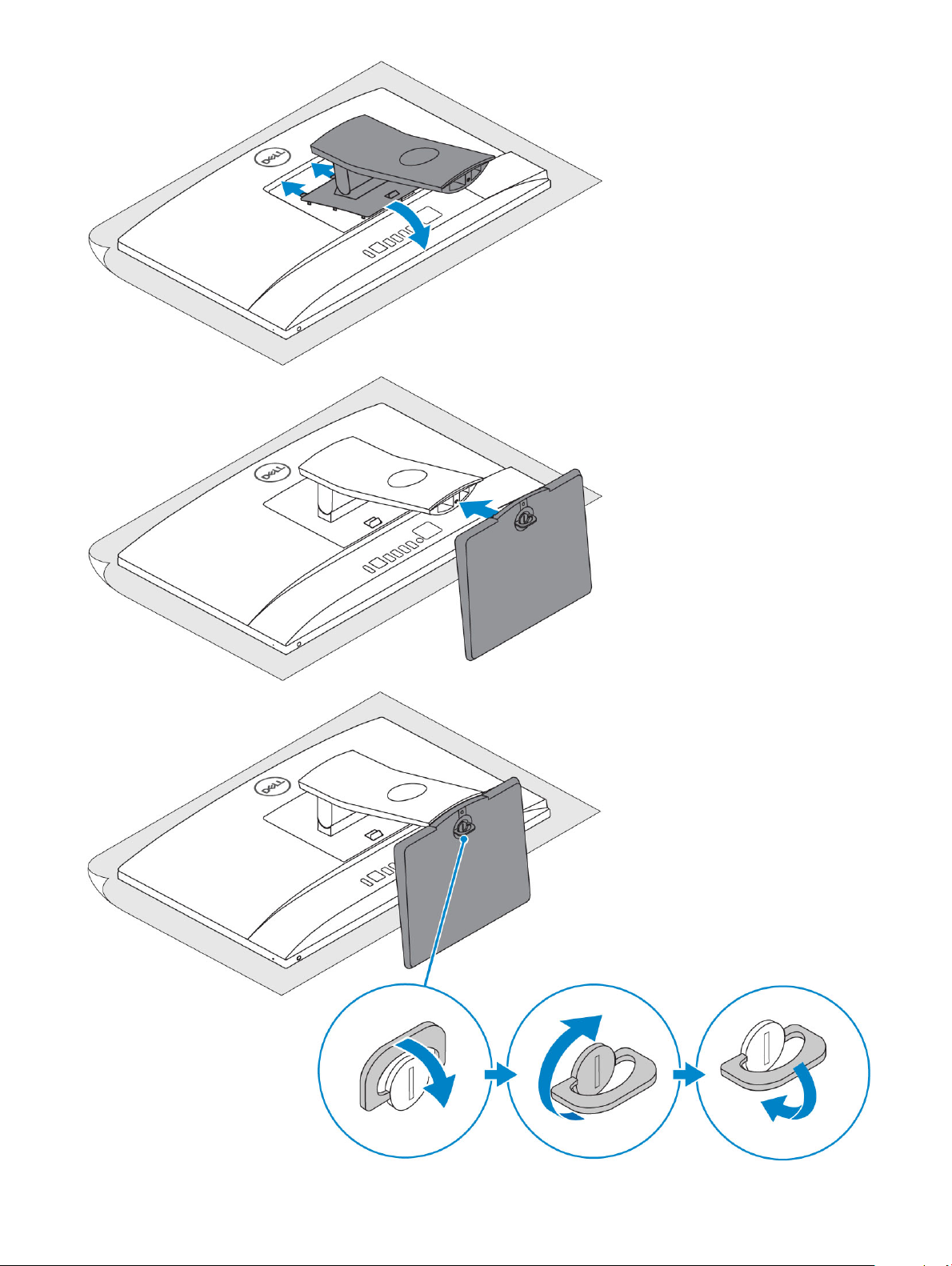
1 Set up the stand.
Basic All-in-One stand
1
Set up your computer
Set up your computer 5
Page 6
6 Set up your computer
Page 7

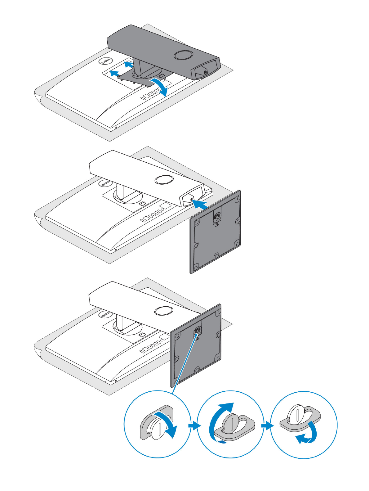
Height Adjustable stand
Set up your computer 7
Page 8
8 Set up your computer
Page 9
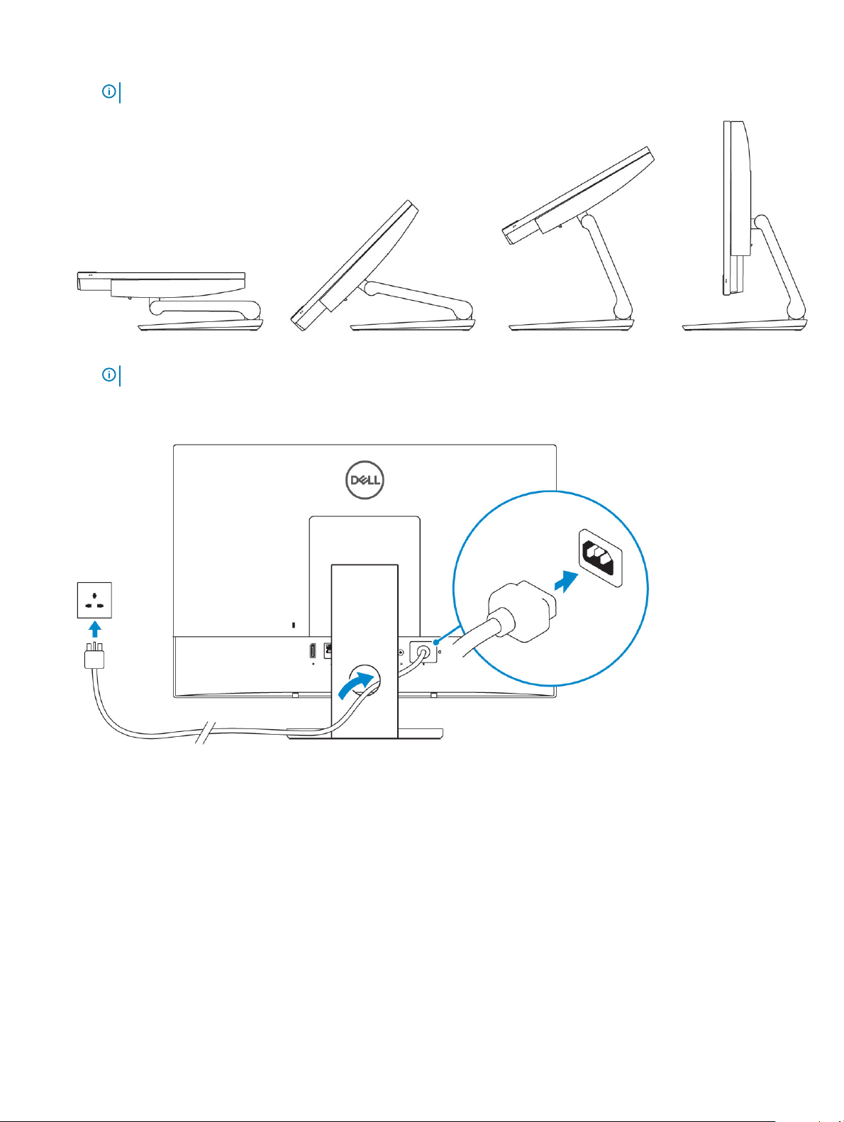
Articulating stand
NOTE: The stand comes assembled in the box.
2 Set up the keyboard and mouse.
NOTE: See the documentation that shipped with the keyboard and mouse.
3 Route the cable through the stand, then connect the power cable.
Basic All-in-One stand
Height Adjustable stand
Set up your computer
9
Page 10
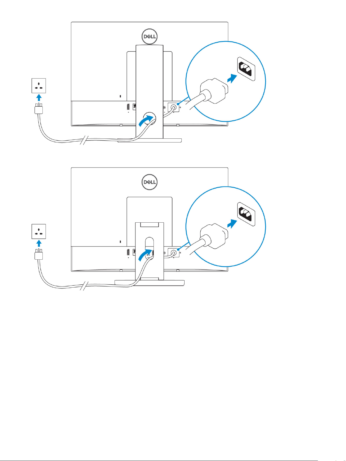
Articulating stand
4 Press the power button.
10
Set up your computer
Page 11

Set up your computer 11
Page 12
Topics:
• Front chassis view
• Back chassis view
• Left chassis view
• Right chassis view
• Bottom chassis view
• Transform
• Pop-Up Camera - optional
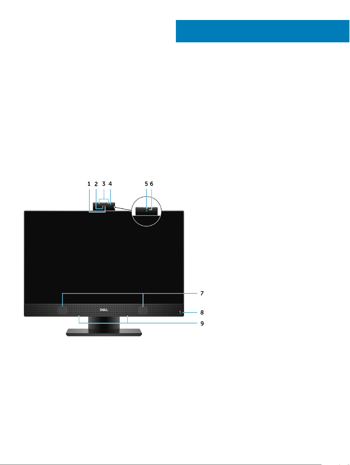
Front chassis view
2
Chassis
1 Full high-denition (FHD) camera (optional) 2 FHD infrared (IR) camera (optional)
3 IR emitters (optional) 4 Camera status light (optional)
5 FHD camera (optional) 6 Camera status light (optional)
7 Speakers 8 Power button/Power-status light/Diagnostic LED
9 Array microphones
Back chassis view
12 Chassis
Page 13
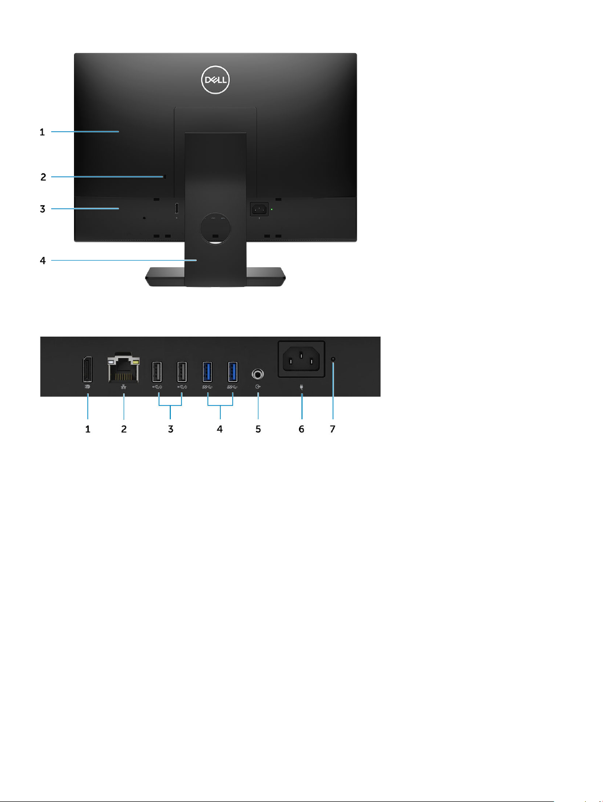
1 Back cover 2 Security lock slot
3 Base cover 4 Stand
1 DisplayPort Dual- Mode Dp++ 2 Network port
3 USB 2.0 ports with Power on/ Wake-up support 4 USB 3.1 Gen 1 ports
5 Audio out port 6 Power connector port
7 Power supply diagnostic light
Chassis 13
Page 14
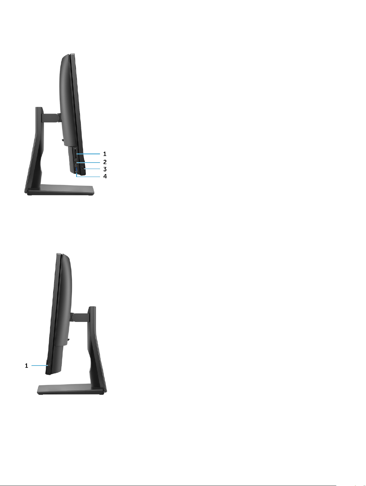
Left chassis view
1 SD card reader 2 USB 3.1 Gen 2 Type-C port
3 Headset/Universal audio port 4 USB 3.1 Gen 1 port with PowerShare
Right chassis view
1
Hard drive activity light
14 Chassis
Page 15

Bottom chassis view
1 Service Tag label 2 Display Built-in Self Test button
Transform
Basic All-in-One stand
Chassis 15
Page 16

Height Adjustable stand
NOTE: When you change the stand orientation from landscape mode to Portrait mode or the other way round, the screen does
not automatically change the orientation. Change the screen orientation in the Intel control panel settings.
16 Chassis
Page 17

Height adjustable stand with optical drive transform
Articulating stand
Chassis
17
Page 18

Pop-Up Camera - optional
NOTE: Extend the camera while using any camera function so that the camera is not blocked.
18 Chassis
Page 19

System specications
NOTE: Oerings may vary by region. The following specications are only those required by law to ship with your computer. For
more information about the conguration of your computer, go to Help and Support in your Windows operating system and
select the option to view information about your computer.
Topics:
• Processor
• Memory
• Storage
• Audio
• Video controller
• Web camera
• Communications - Integrated
• External ports and connectors
• Display
• Power
• Physical system dimensions
• Environmental
3
Processor
Global Standard Products (GSP) are a subset of Dell’s relationship products that are managed for availability and synchronized transitions
on a worldwide basis. They ensure the same platform is available for purchase globally. This allows customers to reduce the number of
congurations managed on a worldwide basis, thereby reducing their costs. They also enable companies to implement global IT standards
by locking in specic product congurations worldwide. The following GSP processors identied below will be made available to Dell
customers.
Device Guard (DG) and Credential Guard (CG) are the security features available on Windows 10 Enterprise. Device Guard is a combination
of enterprise-related hardware and software security features, when congured together, will lock a device down so that it can only run
trusted applications. Credential Guard uses virtualization-based security to isolate secrets (credentials) so that only privileged system
software can access them. Unauthorized access to these secrets can lead to credential theft attacks. Credential Guard prevents these
attacks by protecting NTLM password hashes and Kerberos Ticket Granting Tickets.
NOTE
: Processor numbers are not a measure of performance. Processor availability is subject to change and may vary by region/
country.
Table 1. 9th Generation Intel Core Processor specications
Type
lntel Core i3 - 9100 (4 Cores/6MB/4T/up to 4.2GHz/65W)
lntel Core i3 - 9300 (4 Cores/8MB/4T/up to 4.3GHz/65W)
lntel Core i5 - 9400 (6 Cores/9MB/6T/up to 4.1GHz/65W)
lntel Core i5 - 9500 (6 Cores/9MB/6T/up to 4.4GHz/65W)
Intel Core i5 - 9600 (6 Cores/9MB/6T/up to 4.6GHz/95W)
System specications 19
Page 20

Type
Intel Core i7 - 9700 (8 Cores/12MB/8T/up to 4.9GHz/95W)
Intel Pentium Gold G5420 (2 Cores/4MB/4T/up to 3.8GHz/58W)
Intel Pentium Gold G5600 (2 Cores/4MB/4T/up to 3.9GHz/54W)
Table 2. 8th Generation Intel Core Processor specications
Type
Intel Core i3 - 8100 (4 Cores/6MB/4T/3.6GHz/65W)
Intel Core i3 - 8300 (4 Cores/8MB/4T/3.7GHz/65W)
Intel Core i5 - 8400 (6 Cores/9MB/6T/up to 4.0GHz/65W)
Intel Core i5 - 8500 (6 Cores/9MB/6T/up to 4.1GHz/65W)
Intel Core i5 - 8600 (6 Cores/9MB/6T/up to 4.3GHz/65W)
Intel Core i7 - 8700 (6 Cores/12MB/12T/up to 4.6GHz/65W)
Intel Pentium Gold G5400 (2 Cores/4MB/4T/3.7GHz/65W)
Intel Pentium Gold G5500 (2 Cores/4MB/4T/3.8GHz/65W)
Memory
Table 3. Memory
Minimum memory conguration
Maximum memory conguration
Number of slots
Maximum memory supported per slot
Memory options
Type DDR4 SDRAM Non-ECC memory
Speed
NOTE: Intel Optane Memory does not replace DDR memory or add to RAM capacity.
specications
4 GB
32 GB
2 SODIMM
16 GB
• 4 GB - 1 x 4 GB
• 8 GB - 1 x 8 GB
• 8 GB - 2 x 4 GB
• 16 GB - 1 x 16 GB
• 16 GB - 2 x 8 GB
• 32 GB - 2 x 16 GB
• 2666 MHz
• 2400 MHz on Celeron, Pentium, and i3 processor
20 System specications
Page 21

Storage
Table 4. Storage specications
Primary/Boot drive Form Factor Capacity
One Solid-State Drive (SSD) M.2 2280 Up to 1 TB
One 2.5 inch Hard-Disk Drive (HDD) Approximately (2.760 x 3.959 x 0.374 inches) Up to 2 TB
One 2.5 inch Solid-State Hybrid Drive
(SSHD)
Intel Optane memory M.2 2280 16 GB and 32 GB
NOTE: Optical disk drive is oered separately through the height adjustable stand.
Table 5. Storage congurations
Primary/Boot drive Form Factor
1 x M.2 Drive NA
1 x M.2 Drive 1 x 2.5 inch Drive
1 x 2.5 inch Drive NA
1 x 2.5 inch HDD with M.2 Optane NA
Approximately (2.760 x 3.959 x 0.276
inches)
Up to 1 TB
Audio
Table 6. Audio
Integrated Realtek ALC3246 High Denition Audio
High Denition Stereo support Yes
Number of channels 2
Number of Bits / Audio resolution 16, 20, and 24-bit resolution
Sampling rate (recording/playback) Support 44.1K/48K/96K/192 kHz sample rates
Signal to Noise Ratio 98 dB DAC outputs, 92 dB for ADC inputs
Analog Audio Yes
Waves MaxxAudio Pro Yes
Audio Jack Impedance
Microphone 40K ohm~60K ohm
Line-In N/A
Line-Out 100~150 ohm
Headphone 1~4 ohm
Internal Speaker Power Rating
3 Watt (average) / 4 Watt (peak)
System specications 21
Page 22

Video controller
Table 7. Video
Controller Type Graphics memory type
Intel UHD Graphics 610 UMA Integrated
Intel UHD Graphics 630 UMA Integrated
Table 8. Video port resolution matrix
DisplayPort 1.2
Max resolution - Single display 4096x2160
Max resolution - Dual MST
All resolutions shown at 24bpp and unless specically stated are @ 60 Hz refresh
2560x1600
3440x1440
2560x1080
Web camera
Table 9. Web camera(optional)
Maximum Resolution 2.0 MP
Camera type
Video Resolution
Diagonal Viewing Angle
Power Saving Support Suspend, Hibernation
Automatic Image Control
Webcam Mechanical Privacy Pop up camera
• FHD
• FHD + Infrared (IR)
• FHD - 1080p
• FHD + IR - 1080p + VGA
• FHD - 74.9°
• IR - 88°
Automatic Exposure Control (AE)
Automatic White Balance Control (AWB)
Automatic Gain Control (AGC)
22 System specications
Page 23

Communications - Integrated
Table 10. Communications - Integrated
Network adapter Integrated Intel i219-V 10/100/1000 Mb/s Ethernet (RJ-45 ) with
Intel Remote Wake UP and PXE
External ports and connectors
Table 11. External ports and connectors
USB 2.0 (Side/Rear/Internal) 0/2/0
Two USB 2.0 with Power on/Wake-up support (rear)
USB 3.1 Type A Gen1(Side/Rear/Internal) 2/2/0
• One USB 3.1 Gen 1 port with PowerShare (side)
• One USB 3.1 Gen 2 Type-C port (side)
• Two USB 3.1 Gen 1 ports (rear)
USB 3.1 Type C Gen 2 (Side/Rear/Internal) 1/0/0
One USB 3.1 Gen 2 Type-C port (side)
Network Connector (RJ-45) 1 Rear
DisplayPort 1.2 1 Rear
Universal Audio Jack 1 Side
Line-Out for headphones or speakers 1 Rear
Display
Table 12. Display
Type
Screen size (Diagonal) 21.5 inch
Screen technology
Display
Native resolution 1920 x 1080
specications
• Full HD (FHD) touch
• Full HD (FHD) Non-Touch
IPS
WLED
High denition Full HD
Luminance
• FHD Touch - 200 cd/m
• FHD Non-touch - 250 cd/m
System specications 23
Page 24

Active area dimensions 476.10 mm x 267.80 mm
Height 287.00 mm
Width 489.3 mm
Megapixels 2M
Pixels Per Inch (PPI) 102
Pixel pitch 0.2745 mm x 0.2745 mm
Color depth 16.7 M
Contrast ratio (min) 600
Contrast ratio (typical) 1000
Response time (max) 25 mil sec
Typical Response time
Refresh rate 60 Hhz
Horizontal viewing angle 89°
Vertical viewing angle 89°
14 mil sec
Power
Table 13. Power
Power Supply Wattage 240W EPA Platinum 155W EPA Bronze
AC input Voltage Range 100 – 240 Vac 100 – 240 Vac
AC input current (low AC range/high AC
range)
AC input Frequency 47HZ - 63HZ 47HZ - 63HZ
AC holdup time (80% load) 16 mini sec 16 mini sec
Average Eciency 90-92-89% @ 20-50-100% load 82-85-82% @ 20-50-100% load
Typical Eciency (Active PFC) N/A N/A
3.6A/1.8A 3.6A/1.8A
NOTE: The typical eciency of Active PFC Power Supply is 70%. APFC Power Supply is not oered with OptiPlex 5270
AIO
DC parameters
+12.0 v output NA NA
+19.5 v output 19.5VA - 8.5A and 19.5VB - 10.5A 19.5VA - 7.5A and 19.5VB - 7.0A
+19.5 v output auxiliary output 19.5VA - 0.5A and 19.5VB - 1.75A
Standby mode 19.5VA - 0.5A and 19.5VB -
1.75a
24 System specications
19.5VA - 0.5A and 19.5VB - 1.75A
Standby mode 19.5VA - 0.5A and 19.5VB -
1.75a
Page 25

Max total power 240 W 155 W
Max combined 12.0 v power (note: only if
more than one 12 v rail)
BTUs/h (based on PSU max wattage) 819 BTU 529 BTU
Power Supply Fan N/A N/A
Compliance
Erp Lot6 Tier 2 0.5watt requirement Yes Yes
Climate Savers / 80Plus Compliant Yes Yes
Energy Star 7.0/7.1 Qualied Yes Yes
FEMP Standby Power Compliant Yes Yes
Table 14. Thermal Dissipation
Power Graphics Heat dissipation Voltage
155 W Integrated gfx 155 * 3.4125 = 529 BTU/hr 100 to 240 VAC , 50 to 60 Hz , 3
Table 15. CMOS battery
3.0v CMOS battery (Type and estimated battery life)
N/A N/A
A/1.5 A
Brand Type Voltage Composition Life
VIC-DAWN CR-2032 3V Lithium Continuous Discharge
Under 30 kΩ Load till
2.0V End-Voltage at the
temperature of 23°C
±3°C. The batteries
should be submitted to
150 temperature cycles
from 60°C~-10°C, and
then be stored for more
than 24hours at 23°C
±3°C
JHIH HONG CR-2032 3V Lithium
MITSUBISHI CR-2032 3V Lithium
Continuous Discharge
Under 15 kΩ Load to 2.5V
End-Voltage.
20°C±2°C: 940Hrs or
longer; 910Hrs or longer
after 12 months.
Continuous Discharge
Under 15 kΩ Load to 2.0V
End-Voltage.
20°C±2°C: 1000Hrs or
longer; 970Hrs or longer
after 12 months.
0°C±2°C: 910Hrs or
longer; 890Hrs or longer
after 12 months.
System specications 25
Page 26

Physical system dimensions
NOTE: System weight and shipping weight is based on a typical conguration and may vary based on PC conguration. A typical
conguration includes: integrated graphics and one hard drive.
Table 16. System dimensions
Non-touch chassis weight without stand (pounds / kilograms) 11.75 / 5.33
Touch chassis weight without stand (pounds / kilograms) 12.65 / 5.74
Non-touch chassis dimensions (system without stand):
Height (inches / centimeters) 12.95 / 32.90
Width (inches / centimeters) 19.61 / 49.80
Depth (inches / centimeters) 2.15 / 5.45
Touch chassis dimensions (system without stand):
Height (inches / centimeters) 12.95 / 32.90
Width (inches / centimeters) 19.61 / 49.80
Depth (inches / centimeters) 2.15 / 5.45
Basic stand dimensions
Height (inches / centimeters) 25.26 cm
Width x Depth (inches / centimeters) 9.21 x 7.60 / 23.40 x 19.30
Weight (pounds / kilograms) 5.18 / 2.35
Height adjustable stand dimensions
Width x Depth (inches / centimeters) 10.09 x 8.86 / 25.64 x 22.50
Weight (pounds / kilograms) 6.64 / 3.01
Height adjustable stand with optical disk drive dimensions
Width x Depth (inches / centimeters)
Weight (pounds / kilograms)
Articulating stand dimensions
Height (inches / centimeters) 23.35 cm
Width x Depth (inches / centimeters) 10.0 x 9.98 / 25.42 x 25.36
11.34 x 10.77/ 28.8 x 27.35
8.20 / 3.72
Weight (pounds / kilograms) 7.58 / 3.44
Packaging parameters with basic stand (includes packaging material)
26 System specications
Page 27

Height (inches / centimeters) 19.13 / 48.60
Width (inches / centimeters) 31.42 / 79.80
Depth (inches / centimeters) 7.56 / 19.20
Shipping weight (pounds / kilograms - includes packaging
materials)
Packaging parameters with height adjustable stand
Height (inches / centimeters) 19.13 / 48.60
Width (inches / centimeters) 31.42 / 79.80
Depth (inches / centimeters) 7.56 / 19.20
Shipping weight (pounds / kilograms - includes packaging
materials)
Packaging parameters with height adjustable stand with optical disk drive
Height (inches / centimeters) 19.09 / 48.50
Width (inches / centimeters) 34.53 / 87.70
Depth (inches / centimeters) 7.76 / 19.7
Shipping weight (pounds / kilograms - includes packaging
materials)
Packaging parameters with articulating stand
26.46 / 12.00
27.34 /12.40
29.10 / 13.2
Height (inches / centimeters) 19.09 / 48.50
Width (inches / centimeters) 25.59 / 65.00
Depth (inches / centimeters) 7.76 / 19.70
Shipping weight (pounds / kilograms - includes packaging
materials)
27.34 / 12.40
Environmental
NOTE
: For more details on Dell Environmental features, please to go to Environmental Attributes section. See your specic
region for availability.
Table 17. Environmental
Recyclable packaging Yes
BFR/PVC—free chassis No
Vertical orientation packaging support Yes
MultiPack packaging
Energy Ecient Power Supply Yes
No
System specications 27
Page 28

System setup
System setup enables you to manage your hardware and specify BIOS level options. From the System setup, you can:
• Change the NVRAM settings after you add or remove hardware
• View the system hardware conguration
• Enable or disable integrated devices
• Set performance and power management thresholds
• Manage your computer security
Topics:
• System setup
• Navigation keys
• Boot Sequence
• Entering BIOS setup program
• General screen options
• System conguration screen options
• Security screen options
• Secure boot screen options
• Intel Software Guard Extensions screen options
• Performance screen options
• Power Management screen options
• POST Behavior screen options
• Manageability
• Virtualization support screen options
• Wireless screen options
• Maintenance screen options
• System Log screen options
• Advanced conguration options
• System and setup password
4
System setup
CAUTION
make your computer work incorrectly.
NOTE: Before you change BIOS Setup program, it is recommended that you write down the BIOS Setup program screen
information for future reference.
Use the BIOS Setup program for the following purposes:
• Get information about the hardware installed in your computer, such as the amount of RAM and the size of the hard drive.
• Change the system conguration information.
• Set or change a user-selectable option, such as the user password, type of hard drive installed, and enabling or disabling base devices.
28 System setup
: Unless you are an expert computer user, do not change the settings in the BIOS Setup program. Certain changes can
Page 29

Navigation keys
NOTE: For most of the System Setup options, changes that you make are recorded but do not take eect until you restart the
system.
Keys Navigation
Up arrow Moves to the previous eld.
Down arrow Moves to the next eld.
Enter Selects a value in the selected eld (if applicable) or follow the link in the eld.
Spacebar Expands or collapses a drop-down list, if applicable.
Tab Moves to the next focus area.
Esc Moves to the previous page until you view the main screen. Pressing Esc in the main screen displays a message
that prompts you to save any unsaved changes and restarts the system.
Boot Sequence
Boot Sequence allows you to bypass the System Setup–dened boot device order and boot directly to a specic device (for example:
optical drive or hard drive). During the Power-on Self Test (POST), when the Dell logo appears, you can:
• Access System Setup by pressing F2 key
• Bring up the one-time boot menu by pressing F12 key
The one-time boot menu displays the devices that you can boot from including the diagnostic option. The boot menu options are:
• Removable Drive (if available)
• STXXXX Drive
NOTE
: XXX denotes the SATA drive number.
• Optical Drive (if available)
• SATA Hard Drive (if available)
• Diagnostics
NOTE
: Choosing Diagnostics, will display the ePSA diagnostics screen.
The boot sequence screen also displays the option to access the System Setup screen.
Entering BIOS setup program
1 Turn on (or restart) your computer.
2 During POST, when the DELL logo is displayed, watch for the F2 prompt to appear, and then press F2 immediately.
: The F2 prompt indicates that the keyboard is initialized. This prompt can appear very quickly, so you must watch
NOTE
for it, and then press F2. If you press F2 before the F2 prompt, this keystroke is lost. If you wait too long and the
operating system logo appears, continue to wait until you see the desktop. Then, turn o your computer and try again.
System setup 29
Page 30

General screen options
This section lists the primary hardware features of your computer.
Option Description
System Information
Boot Sequence
• System Information: Displays BIOS Version, Service Tag, Asset Tag, Ownership Tag, Ownership Date,
Manufacture Date, and the Express Service Code.
• Memory Information: Displays Memory Installed, Memory Available, Memory Speed, Memory Channels Mode,
Memory Technology, DIMM A Size, DIMM B Size.
• PCI information: Displays SLOT 1 and SLOT 2
• Processor Information: Displays Processor Type, Core Count, Processor ID, Current Clock Speed, Minimum
Clock Speed, Maximum Clock Speed, Processor L2 Cache, Processor L3 Cache, HT Capable, and 64-Bit
technology.
• Device Information: Displays SATA-0, SATA-1, LOM MAC Address, Video Controller, dGPU Video Controller,
Audio Controller, Wi Fi Device, and Bluetooth Device.
Boot Sequence Allows you to specify the order in which the computer attempts to nd an operating
system. To change the boot order, select the device that you want to change in the list,
which is available on the right-hand side. After you select the device, click up or down
arrows or use your keyboard Page Up or Page Down keys to change the boot options
order. You can also select or de-select from the list using the check-boxes available on the
left hand side. You should enable the Legacy Option ROMs to setup the Legacy boot
mode. This Legacy boot mode is not allowed when you enable the Secure Boot. The
options are:
• Boot Sequence - By default, the Windows Boot Manager check box is selected.
NOTE: The default option might dier based on the operating system
of your computer.
• Boot List Option - The list options are Legacy and UEFI. By default, the option UEFI is
selected.
UEFI Boot Path
Security
NOTE: The default option might dier based on the operating system
of your computer.
• Add Boot Option - Enables you to add a boot option.
• Delete Boot Option - Enables you to delete an existing boot option.
• View - Enables you to view the current boot option in the computer.
• Restore Settings - Restores the default settings of the computer.
• Save Settings - Saves the settings of the computer.
• Apply - Enables you to apply the settings.
• Exit - Exits and starts the computer.
Boot List Options
The option controls whether or not the system prompts the user to enter the Admin password (if set) when
booting a UEFI boot path from the F12 Boot Menu.
• Always, Except Internal HDD
• Always
Allows you to change the boot list option:
• Legacy
• UEFI (enabled by default)
30 System setup
Page 31

Option Description
• Never
Advanced Boot
Options
Date/Time Allows you to change the date and time.
This option allows you the legacy option ROMs to load. By default, the Enable Legacy Option ROMs is disabled.
• Restore Settings - Restores the default settings of the computer
• Save Settings - Saves the settings of the computer
• Apply - Enables you to apply the settings
• Exit - Exits and starts the computer
System conguration screen options
Option Description
Integrated NIC
If you enable UEFI network stack, UEFI network protocols will be available. UEFI network allows pre-os and early os
networking features to use NICs that are enabled. This may be used without PXE turned on. When you enable
Enabled w/PXE, the type of PXE boot (Legacy PXE or UEFI PXE) depends on the current boot mode and type of
option ROMs in use. The UEFI Network Stack is required in order to have UEFI PXE functionality fully enabled.
• Enabled UEFI Network Stack - This option is disabled by default.
Allows you to congure the integrated network controller. The options are:
• Disabled
• Enabled
• Enabled w/PXE: This option is enabled by default.
• Enabled w/Cloud Desktop
NOTE: Depending on the computer and its installed devices, the items listed in this section may or may
not appear.
SATA Operation Allows you to congure the internal SATA hard-drive controller. The options are:
• Disabled
• AHCI
Drives Allows you to congure the SATA drives on board. All drives are enabled by default. The options are:
• SATA-0
• SATA-1
• SATA-4
• M.2 PCIe SSD-0
SMART Reporting This eld controls whether hard drive errors for integrated drives are reported during system startup. This
technology is part of the SMART (Self Monitoring Analysis and Reporting Technology) specication. This option is
disabled by default.
• Enable SMART Reporting
USB Conguration This eld congures the integrated USB controller. If Boot Support is enabled, the system is allowed to boot any
type of USB Mass Storage Devices (HDD, memory key, oppy).
If USB port is enabled, device attached to this port is enabled and available for OS.
System setup 31
Page 32

Option Description
If USB port is disabled, the OS cannot see any device attached to this port.
The options are:
• Enable USB Boot Support
• Enable Rear USB Ports: Include options for 6 ports
• Enable Side USB Ports: Include options for 2 ports
All the options are enabled by default.
NOTE: USB keyboard and mouse always work in the BIOS setup irrespective of these settings.
Rear USB
Conguration
Side USB
Conguration
USB PowerShare This eld congures the USB PowerShare feature behavior. This option allows you to charge external devices using
Audio This eld enables or disables the integrated audio controller. By default, the Enable Audio option is selected. The
OSD Button
Management
Touchscreen This option allows you to enable or disable touchscreen.
Miscellaneous
Devices
This eld allows you to enable or disable rear USB ports.
• Enable/Disable Rear USB Ports
This eld allows you to enable or disable side USB ports.
• Enable/Disable Side USB Ports
the stored system battery power through the USB PowerShare port.
options are:
• Enable Microphone (by default enable)
• Enable Internal Speaker (by default enable)
This eld allows you to enable or disable the OSD (On-Screen Display) buttons on the All-In-One system.
• Disable OSD buttons: This option is unchecked by default.
Allows you to enable or disable the following devices:
• Enable Camera (enabled by default)
• Enable Media Card (enabled by default)
• Disable Media Card
Security screen options
Option
Admin Password Allows you to set, change, or delete the administrator (admin) password.
System Password Allows you to set, change or delete the system password.
32 System setup
Description
NOTE: You must set the admin password before you set the system or hard drive password. Deleting the
admin password automatically deletes the system password and the hard drive password.
NOTE: Successful password changes take eect immediately.
Default setting: Not set
Page 33

Option Description
NOTE: Successful password changes take eect immediately.
Default setting: Not set
Internal HDD-0
Password
Strong Password Allows you to enforce the option to always set strong passwords.
Password
Conguration
Password Bypass Allows you to enable or disable the permission to bypass the System and the Internal HDD password, when they
Password Change Allows you to enable the disable permission to the System and Hard Drive passwords when the admin password is
Allows you to set, change or delete the system’s internal hard disk’s password.
Default setting: Not set
NOTE: Successful password changes take eect immediately.
Default Setting: Enable Strong Password is not selected.
NOTE: If Strong Password is enabled, Admin and System passwords must contain at least one uppercase
character, one lowercase character and be at least 8 characters long.
Allows you to determine the minimum and maximum length of Administrator and System passwords.
are set. The options are:
• Disabled
• Reboot bypass
Default setting: Disabled
set.
Default setting: Allow Non-Admin Password Changes is selected.
UEFI Capsule
rmware Updates
TPM 2.0 Security Allows you to enable the Trusted Platform Module (TPM) during POST. This option is enabled by default. The
Computrace (R) Allows you to activate or disable the optional Computrace software The options are:
This option controls if the system allows BIOS updates via UEFI capsule update package.
• Default setting: Enable UEFI Capsule Firmware Updates is selected.
options are:
• TPM On (Default)
• Clear
• PPI Bypass for Enabled Commands
• PPI Bypass for Disabled Commands
• PPI Bypass for Clear Commands
• Attestation Enable (Default)
• Key Storage Enable (Default)
• SHA - 256 (Default)
• Firmware-TPM (Discrete TPM disabled)
NOTE: Activation, deactivation, and clear options are not aected if you load the setup program's default
values. Changes to this option take eect immediately.
• Deactivate
• Disable
System setup 33
Page 34

Option Description
• Activate
NOTE: The Activate and Disable options will permanently activate or disable the feature and no further
changes will be allowed
Default setting: Deactivate
Chassis Intrusion This eld controls the chassis intrusion feature. The options are:
• Disabled
• Enabled
Default setting: Disabled
OROM Keyboard
Access
Admin Setup
Lockout
Master Password
Lockout
SMM Security
Mitigation
Allows you to set an option to enter the Option ROM Conguration screens using hotkeys during boot. The options
are:
• Enabled
• One Time Enable
• Disabled
Default setting: Enable
Allows you to enable or disable the option to enter setup when an admin password is set.
• Enable Admin Setup Lockout - This option is disabled by default.
When enabled this option will disable master password support. Hard Disk passwords need to be cleared before the
setting can be changed.
• Enable Master Password Lockout
This option enables or disables additional UEFI SMM Security Mitigation protections.
• SMM Security Mitigation
Secure boot screen options
Option
Secure Boot Enable This option enables or disables the Secure Boot feature.
Secure Boot Mode Changes to the Secure Boot operation mode and modies the behavior of Secure Boot to allow evaluation or
Expert Key
Management
34 System setup
Description
• Disabled
• Enabled
Default setting: Enabled.
enforcement of UEFI driver signatures.
• Deployed Mode- This option is enabled by default
• Audit mode
Allows you to manipulate the security key databases only if the system is in Custom Mode. The Enable Custom
Mode option is disabled by default. The options are:
Page 35

Option Description
• PK
• KEK
• db
• dbx
If you enable the Custom Mode, the relevant options for PK, KEK, db, and dbx appear. The options are:
• Save to File—Saves the key to a user-selected le
• Replace from File—Replaces the current key with a key from a user-selected le
• Append from File—Adds a key to the current database from a user-selected le
• Delete—Deletes the selected key
• Reset All Keys—Resets to default setting
• Delete All Keys—Deletes all the keys
NOTE: If you disable the Custom Mode, all the changes made will be erased and the keys will restore to
default settings.
Intel Software Guard Extensions screen options
Option Description
Intel SGX Enable This eld species you to provide a secured environment for running code/storing sensitive information in the
context of the main OS. The options are:
• Disabled
• Enabled
• Software Controlled (default)
Enclave Memory
Size
This option sets SGX Enclave Reserve Memory Size. The options are:
• 32 MB
• 64 MB
• 128 MB
Performance screen options
Option
Multi Core Support Species whether the process will have one or all cores enabled. The performance of some applications will
Intel SpeedStep Allows you to enable or disable the Intel SpeedStep feature.
Description
improve with the additional cores.
• All - This option is enabled by default
• 1
• 2
• 3
• Enable Intel SpeedStep
Default setting: The option is enabled.
System setup 35
Page 36

Option Description
C-States Control Allows you to enable or disable the additional processor sleep states.
• C states
Default setting: The option is enabled.
Intel TurboBoost Allows you to enable or disable the Intel TurboBoost mode of the processor.
• Enable Intel TurboBoost
Default setting: The option is enabled.
Power Management screen options
Option Description
AC Recovery Allows you to enable or disable the computer from turning on automatically when an AC adapter is connected.
• Power O (default)
• Power On
• Last Power State
Enable Intel Speed
Shift Technology
Auto On Time Allows you to set the time at which the computer must turn on automatically. The options are:
Deep Sleep Control Allows you to aggressive the system is at conserving power while Shut down (S5) or in Hybernate (S4) mode.
Fan Control
Override
USB Wake Support Allows you to enable USB devices to wake the system from Standby.
This option is used to enable or disable the Intel speed shift technology support. The option is enabled by default.
• Disabled
• Every Day
• Weekdays
• Select Days
Default setting: Disabled
• Disabled (default)
• Enabled in S5 only
• Enabled in S4 and S5
Controls the speed of the system fan. This option is disabled by default.
NOTE: When enabled, the fan runs at full speed.
NOTE: This feature is only functional when the AC power adapter is connected. If the AC power adapter
is removed during Standby, the system setup removes power from all the USB ports to conserve battery
power.
36 System setup
• Enable USB Wake Support
Default setting: The option is enabled..
Page 37

Option Description
Wake on LAN/
WLAN
Block Sleep This option lets you block entering to sleep (S3 state) in operating system environment.
Allows you to enable or disable the feature that powers on the computer from the O state when triggered by a
LAN signal.
• Disabled: This option is enabled by default.
• LAN Only
• WLAN Only
• LAN or WLAN
• LAN with PXE Boot
Block Sleep (S3 state)
Default setting: This option is disabled
POST Behavior screen options
Option Description
Numlock LED This option option species whether the NumLock LED should be on when the system boots.
• Enable Numlock LED: The option is enabled.
Keyboard Errors This option option species whether the keyboard related errors are reported when it boots.
• Enables Keyboard Error Detection: The option is enabled by default.
Fastboot Allows you to speed up the boot process by bypassing some of the compatibility steps. The options are:
• Minimal
• Thorough (default)
• Auto
Extend BIOS POST
Time
Full Screen Logo . This option displays full screen logo if your image match screen resolution. The option Enable Full Screen Logo is
Warnings and Errors
This option created an additional pre-boot delay.
• 0 seconds (default)
• 5 seconds
• 10 seconds
not selected by default.
• Prompt on Warnings and Errors (default)
• Continue on Warnings
• Continue on Warnings and Errors
Manageability
Option
USB Provision When enabled Intel AMT can be provisioned using the local provisioning le via a USB storage device.
Description
System setup 37
Page 38

Option Description
• Enable USB Provision
MEBx Hotkey This option species whether the MEBx Hotkey function should be enabled when the system boots.
Enable MEBx Hotkey - enabled by default.
Virtualization support screen options
Option Description
Virtualization Allows you to enable or disable the Intel Virtualization Technology.
Enable Intel Virtualization Technology (default).
VT for Direct I/O Enables or disables the Virtual Machine Monitor (VMM) from utilizing the additional hardware capabilities provided
by Intel® Virtualization technology for direct I/O.
Enable VT for Direct I/O - enabled by default.
Trusted Execution This option species whether a Measured Virtual Machine Monitor (MVMM) can utilize the additional hardware
capabilities provided by Intel Trusted Execution Technology. The TPM Virtualization Technology, and Virtualization
technology for direct I/O must be enabled to use this feature.
Trusted Execution - disabled by default.
Wireless screen options
Option
Wireless Device
Enable
Description
Allows you to enable or disable the internal wireless devices.
• WLAN/WiGig
• Bluetooth
All the options are enabled by default.
Maintenance screen options
Option
Service Tag Displays the Service Tag of your computer.
Asset Tag Allows you to create a system asset tag if an asset tag is not already set. This option is not set by default.
SERR Messages This eld controls the SERR message mechanism. Some graphic card required the SERR message.
BIOS Downgrade This eld controls ashing of the system rmware to pervious revisions.
Description
• Enable SERR Messages (default)
Allows BIOS Downgrade (Enabled by default)
Data Wipe This eld enables user to erase data from all internal storage device.
BIOS Recovery Allows you to recover from certain corrupted BIOS conditions from a recover le on the user primary hard drive or
an external USB key. Enabled by default.
38 System setup
Page 39

Option Description
First Power On Date This option lets you set Ownership date. This option is disabled by default.
System Log screen options
Option Description
BIOS Events Allows you to view and clear the System Setup (BIOS) POST events.
Advanced conguration options
Option Description
ASPM Allows you to set the ASPM level.
• Auto (default)
• Disabled
• L1 Only
System and setup password
Table 18. System and setup password
Password type Description
System password Password that you must enter to log on to your system.
Setup password Password that you must enter to access and make changes to the
BIOS settings of your computer.
You can create a system password and a setup password to secure your computer.
CAUTION
CAUTION: Anyone can access the data stored on your computer if it is not locked and left unattended.
NOTE: System and setup password feature is disabled.
: The password features provide a basic level of security for the data on your computer.
Assigning a system setup password
You can assign a new System or Admin Password only when the status is in Not Set.
To enter the system setup, press F2 immediately after a power-on or re-boot.
1 In the System BIOS or System Setup screen, select Security and press Enter.
The Security screen is displayed.
2 Select System/Admin Password and create a password in the Enter the new password eld.
Use the following guidelines to assign the system password:
• A password can have up to 32 characters.
• The password can contain the numbers 0 through 9.
• Only lower case letters are valid, upper case letters are not allowed.
• Only the following special characters are allowed: space, (”), (+), (,), (-), (.), (/), (;), ([), (\), (]), (`).
System setup
39
Page 40

3 Type the system password that you entered earlier in the Conrm new password eld and click OK.
4 Press Esc and a message prompts you to save the changes.
5 Press Y to save the changes.
The computer reboots.
Deleting or changing an existing system setup password
Ensure that the Password Status is Unlocked (in the System Setup) before attempting to delete or change the existing System and/or
Setup password. You cannot delete or change an existing System or Setup password, if the
To enter the System Setup, press F2 immediately after a power-on or reboot.
1 In the System BIOS or System Setup screen, select System Security and press Enter.
The System Security screen is displayed.
2 In the System Security screen, verify that Password Status is Unlocked.
3 Select System Password, alter or delete the existing system password and press Enter or Tab.
4 Select Setup Password, alter or delete the existing setup password and press Enter or Tab.
NOTE: If you change the System and/or Setup password, re-enter the new password when prompted. If you delete the
System and/or Setup password, conrm the deletion when prompted.
5 Press Esc and a message prompts you to save the changes.
6 Press Y to save the changes and exit from System Setup.
The computer reboot.
Password Status is Locked.
40
System setup
Page 41

This chapter details the supported operating systems along with instructions on how to install the drivers.
Topics:
• Operating system
• Downloading drivers
• Intel chipset drivers
• Display adapter drivers
• Audio drivers
• Network drivers
• Camera drivers
• Storage drivers
• Security drivers
• Bluetooth drivers
• USB drivers
5
Software
Operating system
Table 19. Operating system
Operating systems supported
OS recovery media Optional
• Windows 10 Home (64 bit)
• Windows 10 Professional (64 bit)
• Windows 10 Home National Academic
• Windows 10 Pro National Academic
• Windows 10 Pro High end
• Ubuntu 18.04 SP1 LTS (64bit)- Available in August 2019
• NeoKylin 6.0 SP4 (China only)
Download and Use the Dell OS Recovery Image
Downloading drivers
1 Turn on the .
2 Go to Dell.com/support.
3 Click Product Support, enter the Service Tag of your , and then click Submit.
: If you do not have the Service Tag, use the auto detect feature or manually browse for your model.
NOTE
4 Click Drivers and Downloads.
5 Select the operating system installed on your .
6 Scroll down the page and select the driver to install.
7 Click Download File to download the driver for your .
8 After the download is complete, navigate to the folder where you saved the driver le.
Software 41
Page 42

9 Double-click the driver le icon and follow the instructions on the screen.
Intel chipset drivers
Verify if the Intel chipset drivers are already installed in the system.
42 Software
Page 43

Display adapter drivers
Verify if the drivers for the display adapter is already installed in the system.
Audio drivers
Verify if the audio drivers are already installed in the system.
.
Network drivers
Verify if network drivers are already installed in the system.
Camera drivers
Verify if the camera driver is already installed in the system.
Storage drivers
Verify if the storage controller drivers are already installed in the system.
Software
43
Page 44

Verify if the storage drivers are already installed in the system.
Security drivers
Verify if the security drivers are already installed in the system.
Bluetooth drivers
Verify if the Bluetooth drivers are already installed in the system.
USB drivers
Verify if the USB drivers are already installed in the system.
44
Software
Page 45

6
Getting help
Contacting Dell
NOTE: If you do not have an active Internet connection, you can nd contact information on your purchase invoice, packing slip,
bill, or Dell product catalog.
Dell provides several online and telephone-based support and service options. Availability varies by country and product, and some services
may not be available in your area. To contact Dell for sales, technical support, or customer service issues:
1 Go to Dell.com/support.
2 Select your support category.
3 Verify your country or region in the Choose a Country/Region drop-down list at the bottom of the page.
4 Select the appropriate service or support link based on your need.
Getting help 45
 Loading...