

Dell T140 Installation Manual

Dell EMC PowerEdge T140
Technical Guide
Reg ula tor y M ode l: E59 S S eries
Reg ula tor y T ype : E 59S 001
Dec . 2 020
Rev . A 03

Notes, cautions, and warnings
NOTE: A NOTE indicates important information that helps you make better use of your product.
CAUTION: A CAUTION indicates either potential damage to hardware or loss of data and tells you how to avoid
the problem.
WARNING: A WARNING indicates a potential for property damage, personal injury, or death.
© 2018 2020 Dell Inc. or its subsidiaries. All rights reserved. Del l, EMC , and other trademarks are trademarks of Dell Inc. or its subsidiar ies .
Other trademarks may be trademarks of their respective owners.
1
Product overview
Topics:
• Introduction
New technologies
•
Introduction
The Dell EMC PowerEdge T140 is the practical entry-level 1-socket mini-tower server that is easy to use and secure.
New technologies
The PowerEdge T140 is the practical entry-level 1-socket mini-tower server for growing businesses and organizations. The
PowerEdge T140 is easy to use and helps keep your data safe to grow your business. Now with faster 6 core Intel® Xeon®
processors, it helps run applications faster and support for full-feature remote management (iDRAC9), the T140 is also excellent
for Remote Offices / Branch Offices (ROBO) of large institutions. Enhanced by quiet operation and compact mini-tower
dimensions, the PowerEdge T140 1-socket tower server delivers the performance, efficiency and expandability needed for
success.
The T140 is versatile enough to address many customer segments and workloads. Target workloads include:
● Small Businesses and organizations:
○ File and print, mail and messaging, point of sale, web serving, and other collaboration and productivity applications.
● ROBO: Applications and workloads specific to the particular industry, e.g. Retail, Healthcare, Finance, Education, etc.
Table 1. Detailed information of new technologies
New technologies Description
Intel® C246 series chipset Please refer to the chipset section for details.
Intel® Xeon® processor E-2100 and E-2200 Product
Family
Next Generation SW RAID, PERC S140 The new 14G 1-socket servers support the latest S140
iDRAC 9 The new embedded system management solution for 14G
The Intel® processor that works with Intel® C246 series
chipset. The Xeon® E-2100 and E-2200 processors have
increased core count and embedded PCIe lanes that will
improve the IO performance and a lot more features.
software RAID along with H330 and H730P controller cards
with improved functionality and faster performance. New SW
RAID supports RAID 0, 1, 5 and 10.
server features hardware and firmware inventory and alerting,
in depth memory alerting, faster performance, dedicated
gigabit port, email alerts, electronic licensing, editable user
work notes log, and more. Dedicated iDRAC Direct microUSB
port improves at-the-box management.
Product overview 3
Product features
Topics:
• Product comparison
Specifications
•
Product comparison
The following table shows the comparison between the PowerEdge T130 and the PowerEdge T140:
Feature PowerEdge T130 PowerEdge T140
2
Processor
Front Side Bus
Number of processors
Number of cores
L2/L3 cache
Chipset
DIMMs
Min/Max RAM
Hard drive bays
Hard drive types
● Intel® Xeon® processor E3-1200 v6
product family
● Intel® Core™ i3
● Intel® Pentium®
● Intel® Celeron®
● DMI 3.0 ● DMI 3.0
● 1 ● 1
● Up to 4 cores ● Up to 6 cores
● 2.0 MB per core 4 MB or 8 MB ● 2.0 MB per core 8 MB or 12 MB
● Intel® C236 chipset ● Intel® C246 chipset
● 4 UDIMMS DDR4 Up to 2400MT/s ● 4 UDIMMS DDR4 Up to 2666MT/s
● 4GB/64GB ● 8GB/64GB
● 4x 3.5" cabled ● 4x 3.5" cabled
● 3.5" Enterprise SATA 7.2K HDDs
● 3.5" Near Line SAS 7.2K HDDs
● 3.5" 7.2K SATA Entry Drives
● Intel® Xeon® processor E-2100 and
E-2200 product family
● Intel® Core™ i3
● Intel® Pentium®
● Intel® Celeron®
● 3.5" Enterprise SATA 7.2K HDDs
● 3.5" Near Line SAS 7.2K HDDs
● 3.5" 7.2K SATA Entry Drives
External drive bay(s)
Embedded hard drive
controller
Optional storage controller
Boot Optimized Storage
Subsystem (BOSS)
Server management
4 Product features
● 1x slim ODD 9.5mm ● 1x slim ODD 9.5mm
● Chipset based SATA PERC S130
(Embedded SW RAID)
● Non-RAID: 12GB SAS HBA
● RAID: PERC Η 330, PERC H730, PERC
Η830
Not Supported
● Dell Open Manage featuring Dell
Management Console
● Chipset based SATA PERC S140
(Embedded SW RAID)
● Non-RAID: 12GB SAS HBA, PERC
ΗBA330
● RAID: PERC Η 330, PERC H730P
● 2x M.2 240GB (RAID 1 or No RAID) 1x
M.2 240GB (No RAID only)
● Dell Open Manage featuring Dell
Management Console
Feature PowerEdge T130 PowerEdge T140
I/O slots
NIC/LOM
USB
Power supplies
Fans
Form factor
Dimension (HxWxD)
● Lifecycle Controller 3.0
● iDRAC8 Enterprise
● 1x8 Gen3 (x16 connector) FH/HL
● 1x4 Gen3 (x8 connector) FH/HL
● 1x4 Gen3 (x8 connector) FH/HL
● 1x1 Gen3 (x1 connector) FHHL
● 2 X 1GbE LOM ● 2 X 1GbE LOM
● Rear: 2 USB 3.0, 4 USB 2.0
● Front: 1 USB 2.0, 1 USB 3.0
● Internal: 1 USB 3.0
● Non-Redundant D5 290W Bronze EPA
(Auto sensing)
● Non-redundant, non-hot swappable ● Non-redundant, non-hot swappable
● Mini Tower ● Mini Tower
● Height 14.17 in / 36.0 cm
● Width 6.89 in / 17.5 cm
● Depth 17.9 in / 45.4 cm
● Lifecycle Controller 3.0
● iDRAC9 Enterprise
● 1x8 Gen3 (x16 connector) FH/HL
● 1x8 Gen3 (x8 connector) FH/HL
● 1x4 Gen3 (x8 connector) FH/HL
● 1x1 Gen3 (x1 connector) FH/HL
● Rear: 2 USB 3.0, 4 USB 2.0
● Front: 1 USB 3.0, 1 Micro USB 2.0
(Dedicated iDRAC direct)
● Internal: 1 USB 3.0
● Non-Redundant D5 365W Gold EPA
(Auto sensing)
● Height 14.17 in / 36.0 cm
● Width 6.89 in / 17.5 cm
● Depth 17.9 in / 45.4 cm
Weight
● Max 24.91lbs or (11.3 Kgs) ● Max 26.10lbs or (11.84 Kgs)
Specifications
The following table shows the specifications for the PowerEdge T140:
Table 2. Product specifications
Feature Specifications
Form Factor
Processors
Processor sockets
Front Side Bus or HyperTransport
Cache
● Mini Tower
● Intel® Xeon® processor E-2100 and E-2200 product
family
● Intel® Core™ i3
● Intel® Pentium®
● Intel® Celeron
● 1
● DMI
● 2.0 MB per core
● 8 MB or 12 MB
Chipset
Memory
● Intel® C246 Chipset
● Up to 64GB (4 DIMM Slots)
● 8GB/16GB 2666MT/s Unbuffered with ECC only
● Min/Max RAM: 8GB/64GB
Product features 5

Table 2. Product specifications (continued)
Feature Specifications
I/O Slots
RAID Controller
Drive bays
Hard drives
Embedded LOM/NIC
Communications
● 4 Gen3 PCIe slots:
● One x8 slots (one with x16 connectors)
● Two x4 slot (with x8 connector)
● One x1 slot
● Internal controllers: PERC S140, PERC H330, PERC H730P
● External HBAs (non-RAID): 12GB SAS HBA
● Up to four 3.5” cabled SAS or SATA drives
● 3.5” Enterprise SATA 7.2K HDDs
● 3.5” Near Line SAS 7.2K HDDs
● 3.5” 7.2K SATA Client Drives
● Capacity: 1 TB ,2 TB ,4 TB (4TB requires PERC H330 or
H730P)
● Integrated BROADCOM BCM5720 Gigabit Ethernet
Controller
● Optional add-in NICs:
○ 1GB Intel (Dual) Powerville Troi-Stony Dual port 1Gb
Base-T adapter - FH
○ 1GB Intel (Quad) Powerville Lore-Stony Quad port 1Gb
Base-T adapter - FH
○ 1GB Broadcom (Dual) 5720 Bashir Dual port 1Gb Base-
T adapter - FH
○ 1GB Broadcom (Quad) 5719 Cardassia Quad port 1Gb
Base-T adapter - FH
Power supply
Availability
Video
Remote Management
Systems Management
Featured Database Applications
● Cabled 365W Gold (100–240 V AC)
● ECC Memory, ADD-in RAID, TPM/CTPM
● Integrated Matrox G200 with iDRAC9
● Base Management Console,IDRAC Express and IDRAC
Enterprise (Upsell option)
● Dell Open Manage featuring Dell Management Console
● Lifecycle Controller 3.0
● iDRAC9 Enterprise
● Microsoft® SQL Server® solutions
6 Product features

Topics:
• Front view of the system
Rear view of the system
•
• Inside the system
• Locating the Service Tag of your system
3
Chassis views and features
Chassis views and features 7
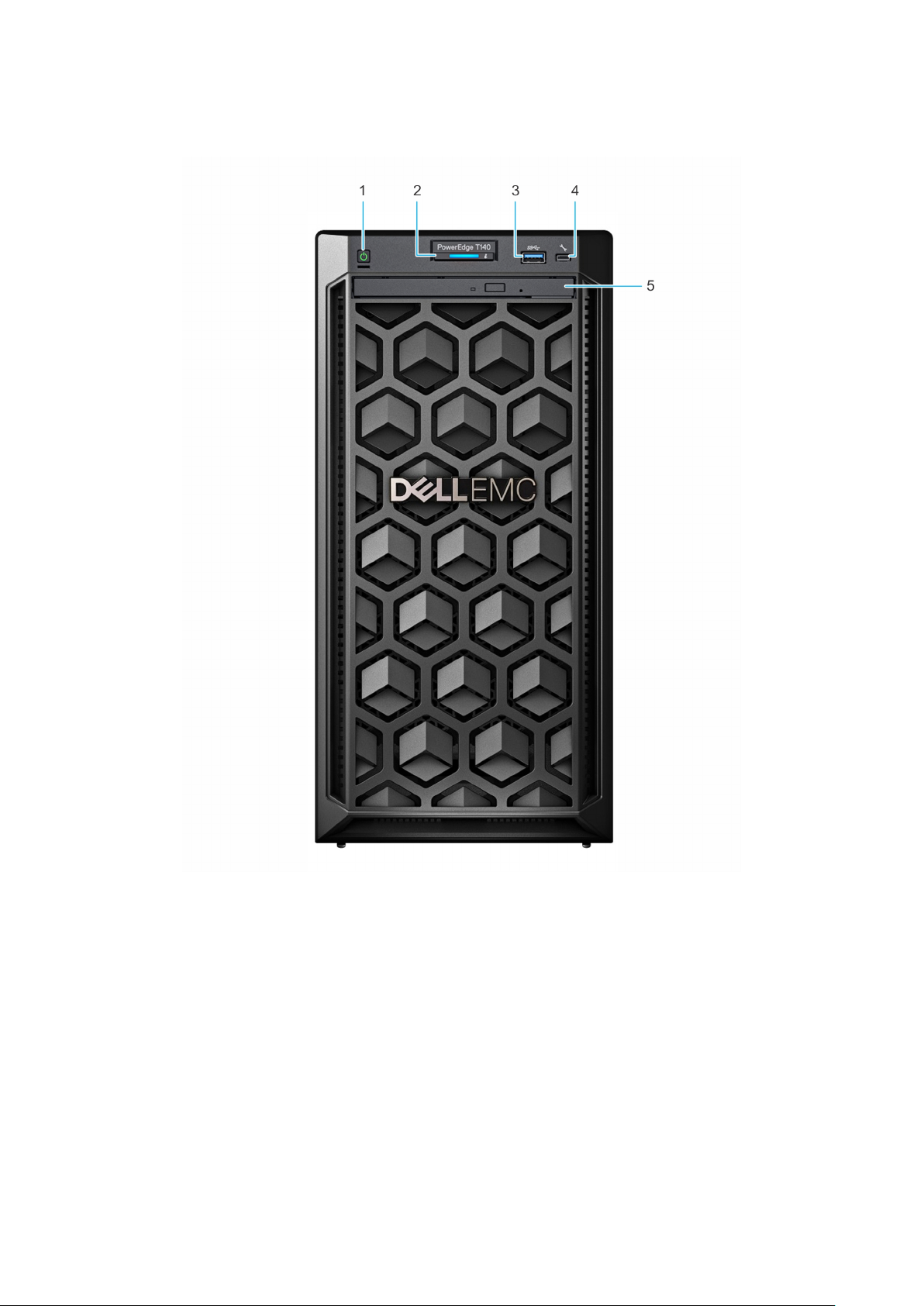
Front view of the system
Figure 1. Front view of the system
Power button 2. System health and ID indicator
1.
3. USB 3.0 port 4. iDRAC direct micro USB port
5. Optical drive (optional)
For more information about the ports, see the Ports and connectors specifications section.
8
Chassis views and features
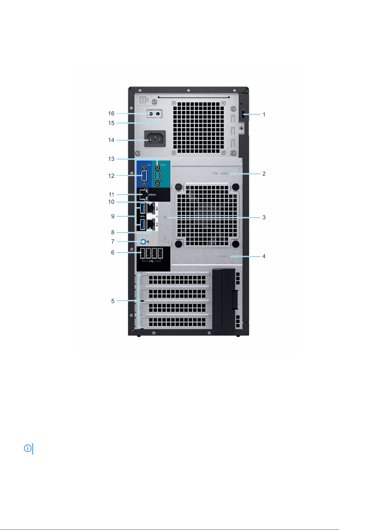
Rear view of the system
Figure 2. Rear view of the system
Security Cable Lock 2. iDRAC MAC address and iDRAC secure password label
1.
3. Service Tag, Express Service Code, QRL label 4. OpenManage Mobile (OMM) label
5. PCIe expansion card slots (4) 6. USB 2.0 port (4)
7. System identification button 8. NIC port (Gb 2)
9. USB 3.0 ports (2) 10. NIC port (Gb 1)
11. iDRAC dedicated NIC port 12. VGA port
13. Serial port 14. Power supply unit
15. PSU Built-in Self Test (BIST) LED 16. PSU Built-in Self Test (BIST) Button
NOTE: For more information about the ports and connectors, see the Ports and connectors specifications section.
Chassis views and features 9
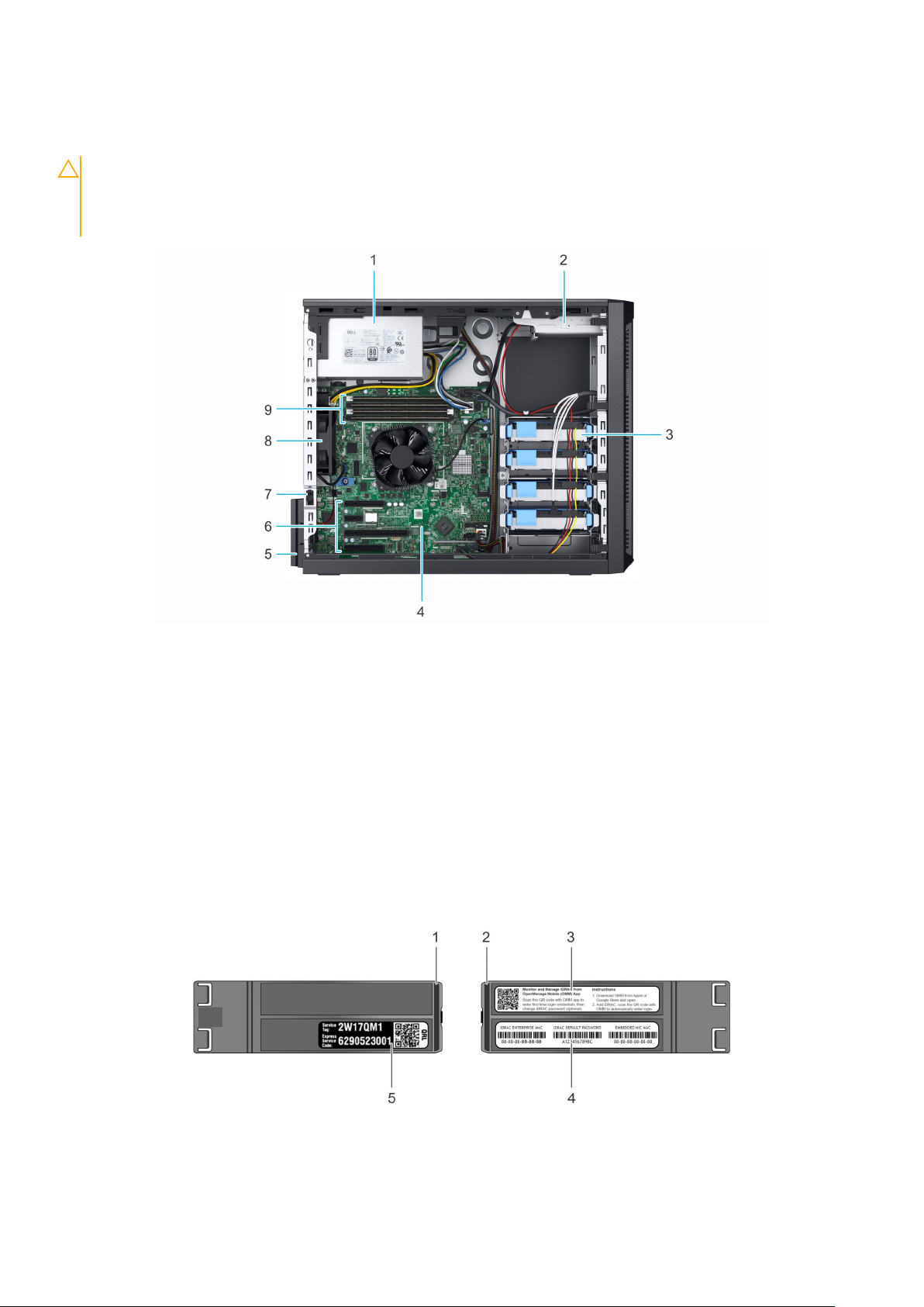
Inside the system
CAUTION: Many repairs may only be done by a certified service technician. You should only perform
troubleshooting and simple repairs as authorized in your product documentation, or as directed by the online or
telephone service and support team. Damage due to servicing that is not authorized by Dell is not covered by
your warranty. Read and follow the safety instructions that are shipped with your product.
Figure 3. Inside the system
Cabled Power Supply Unit (PSU) 2. Optical drive
1.
3. Cabled drives (4) 4. System board
5. Expansion card retention latch 6. PCIe expansion card slots (4)
7. Intrusion switch 8. Fan
9. Memory module sockets
Locating the Service Tag of your system
You can identify your system using the unique Express Service Code and Service Tag. Pull out the information tag in front of the
system to view the Express Service Code and Service Tag. Alternatively, the information may be on a sticker on the chassis of
the system. The mini Enterprise Service Tag (EST) is found on the back of the system. This information is used by Dell to route
support calls to the appropriate personnel.
Figure 4. Locating Service Tag of your system
1.
Information tag (top view) 2. Information tag (back view)
10 Chassis views and features

3. OpenManage Mobile (OMM) label 4. iDRAC MAC address and iDRAC secure password label
5. Service Tag
Chassis views and features 11
 Loading...