

Dell T110 User Manual

Dell™ PowerEdge™ T110
Systems
Hardware Owner’s
Manual

Notes, Cautions, and Warnings
NOTE: A NOTE indicates important information that helps you make better use of
your computer.
CAUTION: A CAUTION indicates potential damage to hardware or loss of data if
instructions are not followed.
WARNING: A WARNING indicates a potential for property damage, personal
injury, or death.
____________________
Information in this document is subject to change without notice.
© 2009 Dell Inc. All rights reserved.
Reproduction of these materials in any manner whatsoever without the written permission of Dell Inc.
is strictly forbidden.
Trademarks used in this text: Dell, the DELL logo, and PowerEdge are trademarks of Dell Inc.;
Microsoft, Windows, W indows Server , and MS-DOS are either trademarks or registered trademarks of
Microsoft Corporation in the United States and/or other countries.
Other trademarks and trade names may be used in this document to refer to either the entities claiming
the marks and names or their products. Dell Inc. disclaims any proprietary interest in trademarks and
trade names other than its own.
August 2009 Rev. A00

Contents
1 About Your System . . . . . . . . . . . . . . . . . . 11
Accessing System Features During Startup. . . . . . . 11
Front-Panel Features and Indicators
Back-Panel Features and Indicators
. . . . . . . . . . 12
. . . . . . . . . . 14
Guidelines for Connecting External Devices
NIC Indicator Codes
Power Selection
Diagnostic Lights
System Messages
Warning Messages
Diagnostics Messages
Alert Messages
Other Information You May Need
. . . . . . . . . . . . . . . . . . . 16
. . . . . . . . . . . . . . . . . . . . . 17
. . . . . . . . . . . . . . . . . . . . 18
. . . . . . . . . . . . . . . . . . . . 20
. . . . . . . . . . . . . . . . . . . 33
. . . . . . . . . . . . . . . . . 33
. . . . . . . . . . . . . . . . . . . . . 33
. . . . . . . . . . . . 33
. . . . . . 15
Contents 3

2 Using the System Setup Program and
UEFI Boot Manager
Choosing the System Boot Mode . . . . . . . . . . . . 35
. . . . . . . . . . . . . . . . . 35
Entering the System Setup Program
Responding to Error Messages
. . . . . . . . . . . 36
. . . . . . . . . . . 36
Using the System Setup Program
Navigation Keys
. . . . . . . . . . . . . . . . . . . 36
System Setup Options . . . . . . . . . . . . . . . . . . 37
Main Screen
Memory Settings Screen
Processor Settings Screen
SATA Settings Screen
Boot Settings Screen
Integrated Devices Screen
PCI IRQ Assignments Screen
Serial Communication Screen
Power Management Screen
System Security Screen
Exit Screen
Entering the UEFI Boot Manager
. . . . . . . . . . . . . . . . . . . . 37
. . . . . . . . . . . . . . 39
. . . . . . . . . . . . . 39
. . . . . . . . . . . . . . . . 40
. . . . . . . . . . . . . . . . 41
. . . . . . . . . . . . . 42
. . . . . . . . . . . . 43
. . . . . . . . . . . 43
. . . . . . . . . . . . 44
. . . . . . . . . . . . . . 45
. . . . . . . . . . . . . . . . . . . . . 47
. . . . . . . . . . . . . 47
Using the UEFI Boot Manager
Navigation Keys
UEFI Boot Manager Screen
UEFI Boot Settings Screen
System Utilities Screen
. . . . . . . . . . . . . . . . . . . 47
. . . . . . . . . . . . . 48
. . . . . . . . . . . . . 48
. . . . . . . . . . . . . . . 49
4 Contents

System and Setup Password Features . . . . . . . . . 49
Using the System Password
Using the Setup Password
. . . . . . . . . . . . 49
. . . . . . . . . . . . . 52
Embedded System Management
Baseboard Management Controller Configuration
Entering the BMC Setup Module
. . . . . . . . . . . . 53
. . . . 54
. . . . . . . . . . 54
3 Installing System Components . . . . . . . . 55
Recommended Tools. . . . . . . . . . . . . . . . . . . 55
Inside the System
Opening and Closing the System
Opening the System
Closing the System
Front Bezel
Removing the Front Bezel
Installing the Front Bezel
Removing Front Bezel Insert
Installing Front Bezel Insert
EMI Filler Panel
Removing an EMI Filler Panel
Installing an EMI Filler Panel
. . . . . . . . . . . . . . . . . . . . 56
. . . . . . . . . . . . 57
. . . . . . . . . . . . . . . . 57
. . . . . . . . . . . . . . . . . 58
. . . . . . . . . . . . . . . . . . . . . . . . 59
. . . . . . . . . . . . . 59
. . . . . . . . . . . . . . 60
. . . . . . . . . . . . 60
. . . . . . . . . . . . 61
. . . . . . . . . . . . . . . . . . . . . 61
. . . . . . . . . . . 61
. . . . . . . . . . . . 62
Contents 5

Optical and Tape Drives (Optional) . . . . . . . . . . . 63
Removing an Optical or Tape Drive
Installing an Optical or Tape Drive
. . . . . . . . . 63
. . . . . . . . . 66
Hard Drives
. . . . . . . . . . . . . . . . . . . . . . . . 68
Hard Drive Installation Guidelines
Removing a Hard Drive
Installing a Hard Drive
. . . . . . . . . . . . . . . 68
. . . . . . . . . . . . . . . 70
. . . . . . . . . 68
Removing a Hard Drive from a
Hard-Drive Bracket
Expansion Card Stabilizer
Removing the Expansion Card Stabilizer
Installing the Expansion Card Stabilizer
. . . . . . . . . . . . . . . . . 71
. . . . . . . . . . . . . . . . 72
. . . . . . 72
. . . . . . 72
Cooling Shroud . . . . . . . . . . . . . . . . . . . . . . 73
Removing the Cooling Shroud
Installing the Cooling Shroud
Expansion Cards
. . . . . . . . . . . . . . . . . . . . . 75
Expansion Card Installation Guidelines
Removing an Expansion Card
Installing an Expansion Card
SAS Controller Expansion Card
System Memory
. . . . . . . . . . . . . . . . . . . . . 80
. . . . . . . . . . . 73
. . . . . . . . . . . . 74
. . . . . . . 75
. . . . . . . . . . . . 76
. . . . . . . . . . . . 78
. . . . . . . . . . . 79
General Memory Module
Installation Guidelines
Mode-Specific Guidelines
Removing Memory Modules
Installing Memory Modules
. . . . . . . . . . . . . . . 80
. . . . . . . . . . . . . 80
. . . . . . . . . . . . 82
. . . . . . . . . . . . . 83
6 Contents
Processor
. . . . . . . . . . . . . . . . . . . . . . . . . 85
Removing the Processor
Installing a Processor
. . . . . . . . . . . . . . 85
. . . . . . . . . . . . . . . . 88

Cooling Fan. . . . . . . . . . . . . . . . . . . . . . . . 89
Removing the Cooling Fan
Installing the Cooling Fan
. . . . . . . . . . . . . 89
. . . . . . . . . . . . . . 90
System Battery
Replacing the System Battery
Power Supply
Removing the Power Supply
Installing the Power Supply
Internal USB Memory Key
Chassis Intrusion Switch
Removing the Chassis Intrusion Switch
Installing the Chassis Intrusion Switch
Control Panel Assembly
Removing the Control Panel Assembly
Installing the Control Panel Assembly
System Board
Removing the System Board
Installing the System Board
. . . . . . . . . . . . . . . . . . . . . . 91
. . . . . . . . . . . 91
. . . . . . . . . . . . . . . . . . . . . . 93
. . . . . . . . . . . . 93
. . . . . . . . . . . . 94
. . . . . . . . . . . . . . . 95
. . . . . . . . . . . . . . . . 96
. . . . . . 96
. . . . . . 97
. . . . . . . . . . . . . . . . . 98
. . . . . . . 98
. . . . . . . 100
. . . . . . . . . . . . . . . . . . . . . . 101
. . . . . . . . . . . . 101
. . . . . . . . . . . . 102
4 Troubleshooting Your System . . . . . . . . 105
Safety First—For You and Your System . . . . . . . . . 105
Troubleshooting System Startup Failure
Troubleshooting External Connections
Troubleshooting the Video Subsystem
Troubleshooting a USB Device
. . . . . . . . . . . . . 106
. . . . . . . . 105
. . . . . . . . . 105
. . . . . . . . . 106
Contents 7

Troubleshooting a Serial I/O Device. . . . . . . . . . 107
Troubleshooting a NIC
Troubleshooting a Wet System
Troubleshooting a Damaged System
Troubleshooting the System Battery
Troubleshooting Power Supply
Troubleshooting System Cooling Problems
. . . . . . . . . . . . . . . . . 107
. . . . . . . . . . . . . 108
. . . . . . . . . . 109
. . . . . . . . . . 110
. . . . . . . . . . . . 111
. . . . . . 111
Troubleshooting Cooling Fan . . . . . . . . . . . . . 112
Troubleshooting System Memory
Troubleshooting an Internal USB Key
Troubleshooting an Optical Drive
Troubleshooting a Tape Backup Unit
Troubleshooting a Hard Drive
Troubleshooting Expansion Cards
Troubleshooting the Processor
. . . . . . . . . . . 113
. . . . . . . . . 114
. . . . . . . . . . . 115
. . . . . . . . . 116
. . . . . . . . . . . . . 117
. . . . . . . . . . . 118
. . . . . . . . . . . . 119
5 Running the System Diagnostics . . . . . . 121
8 Contents
Using Online Diagnostics . . . . . . . . . . . . . . . 121
Embedded System Diagnostics Features
When to Use the Embedded System Diagnostics
Running the Embedded System Diagnostics
System Diagnostics Testing Options
. . . . . . . 121
. . . 122
. . . . . 122
. . . . . . . . . . 122

Using the Custom Test Options . . . . . . . . . . . . . 123
Selecting Devices for Testing
Selecting Diagnostics Options
Viewing Information and Results
. . . . . . . . . . . 123
. . . . . . . . . . . 123
. . . . . . . . . . 124
6 Jumpers and Connectors . . . . . . . . . . . 125
System Board Jumper . . . . . . . . . . . . . . . . . . 125
System Board Connectors
Disabling a Forgotten Password
. . . . . . . . . . . . . . . . 126
. . . . . . . . . . . . 128
7 Getting Help. . . . . . . . . . . . . . . . . . . . . . 129
Contacting Dell . . . . . . . . . . . . . . . . . . . . . 129
Glossary . . . . . . . . . . . . . . . . . . . . . . . . . . . . 131
Index
. . . . . . . . . . . . . . . . . . . . . . . . . . . . . . 139
Contents 9

10 Contents

About Your System
Accessing System Features During Startup
The following keystrokes provide access to system features during startup:
Keystroke Description
<F2> Enters the System Setup program. See "Using the System Setup
Program and UEFI Boot Manager" on page 35.
<F10> Enters System Services, which opens the Unified Server
Configurator (USC). The USC allows you to access utilities such as
embedded system diagnostics. For more information, see the USC
documentation.
<F11> Enters the BIOS Boot Manager or the
Firmware Interface (
system's boot configuration. See "Using the System Setup Program
and UEFI Boot Manager" on page 35.
<F12> Starts Preboot eXecution Environment (PXE) boot.
<Ctrl><E> Enters the Baseboard Management Controller (BMC)
Configuration Utility, which allows access to the System Event Log
(SEL) and configuration of remote access to the system. For more
information, see the BMC user documentation.
<Ctrl><C> Enters the SAS Configuration Utility. For more information, see
the SAS adapter documentation.
<Ctrl><R> Enters the PERC configuration utility. For more information, see
the PERC card documentation.
<Ctrl><S> Enters the utility to configure NIC settings for PXE boot. For more
information, see the documentation for your integrated NIC.
UEFI) Boot Manager, depending on the
Unified Extensible
About Your System 11
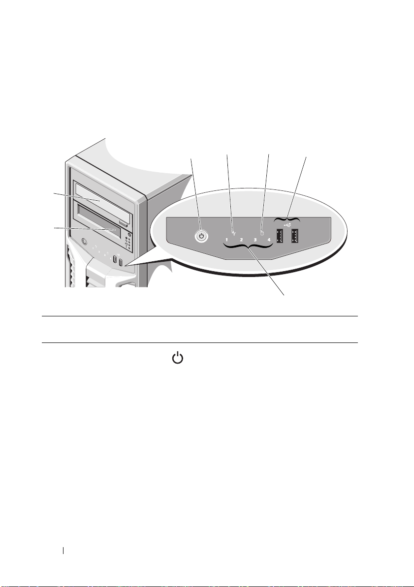
Front-Panel Features and Indicators
1
5
23
4
7
6
Figure 1-1. Front Panel Features and Indicators
Item Indicator, Button, or
Connector
1 Power-on indicator,
power button
Icon Description
The power-on indicator lights when the
system power is on.
The power button controls the DC
power supply output to the system.
NOTE: When powering on the system, the
video monitor can take from several
seconds to over 2 minutes to display an
image, depending on the amount of
memory installed in the system.
NOTE: On ACPI-compliant operating
systems, turning off the system using the
power button causes the system to
perform a graceful shutdown before
power to the system is turned off.
12 About Your System

Item Indicator, Button, or
Connector
2 System health
indicator
3 Hard drive activity
indicator
4 USB connectors (2) Connects USB devices to the system.
5 Diagnostic indicator
lights (4)
6 Tape drive (optional) One optional half-height (using one
7 Optical drive
(optional)
Icon Description
The system health indicator blinks
amber when a system fault is detected.
The hard drive activity indicator lights
up when the hard drive is in use.
The ports are USB 2.0-compliant.
The four diagnostic indicator lights
display error codes during system
startup. See "Diagnostic Lights" on
page 18.
drive bay).
One optional SATA DVD-ROM drive or
DVD+/-RW drive.
NOTE: DVD devices are data only.
About Your System 13
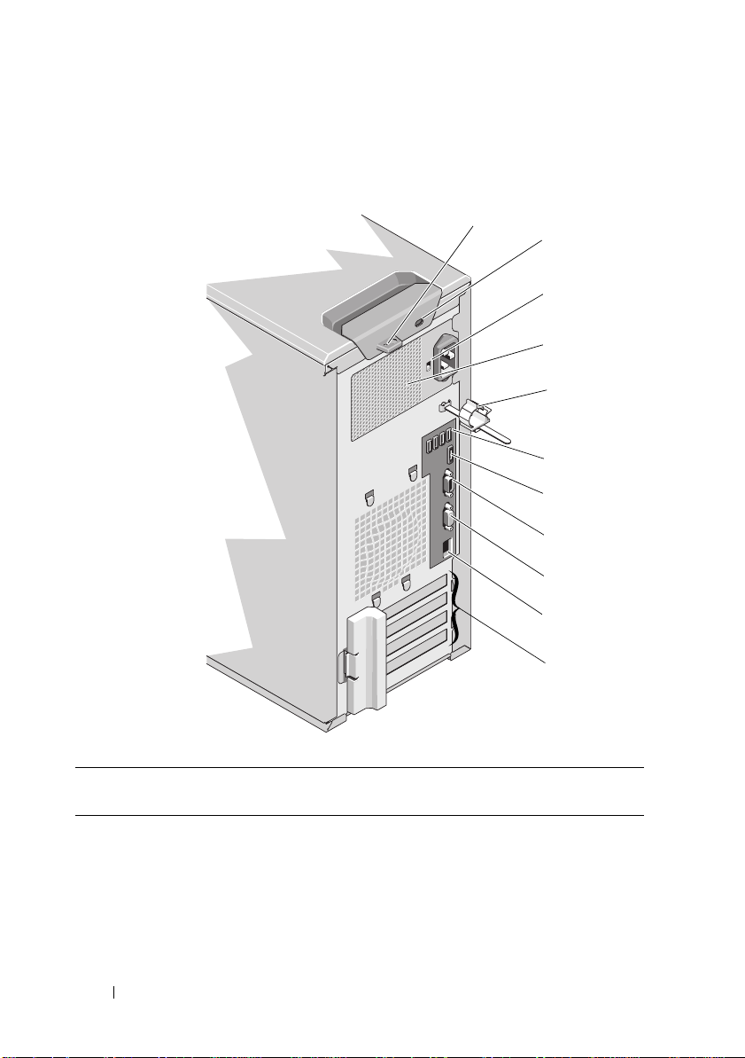
Back-Panel Features and Indicators
8
9
7
6
10
1
4
11
2
3
5
Figure 1-2. Back-Panel Features and Indicators
Item Indicator, Button, or
Connector
1 Padlock ring Locks the cover release latch
2 Security cable slot Connects a cable lock to the system
3 Voltage selection
switch
Icon Description
Sets the voltage for the power supply to
the voltage that most closely matches
the AC power available at your location
14 About Your System
Item Indicator, Button, or
Connector
4 Power supply 305 W power supply
5 Cable clasp Secures the power cable
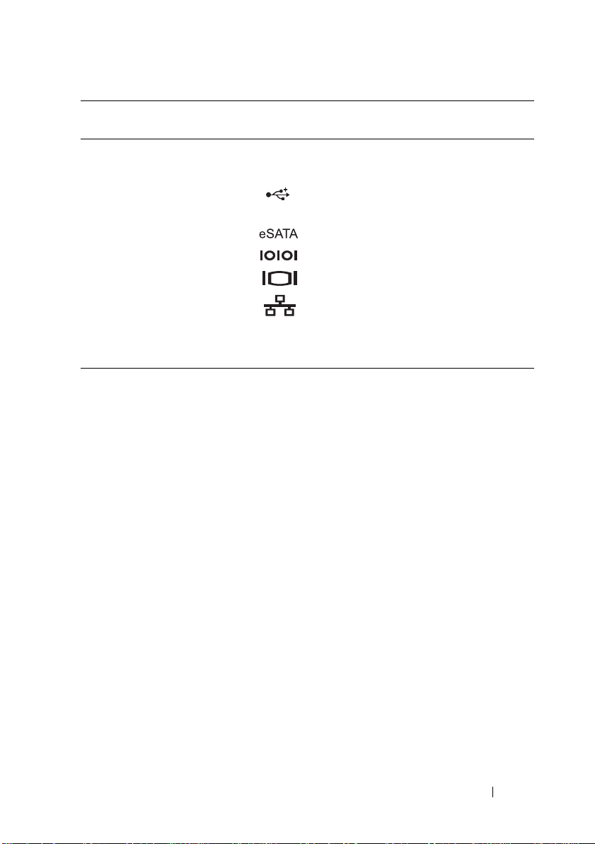
6 USB connectors (4) Connects USB devices to the system.
7 eSATA connector Connects additional storage devices
8 Serial connector Connects a serial device to the system
9 Video connector Connects a VGA display to the system
10 Ethernet connector Integrated 10/100/1000 NIC connector
Icon Description
The ports are USB 2.0-compliant
11 PCIe expansion card
slots (4)
Connects up to four PCI Express
expansion cards
Guidelines for Connecting External Devices
• Turn off power to the system and external devices before attaching a new
external device. Turn on any external devices before turning on the system
(unless the documentation for the device specifies otherwise).
• Ensure that the appropriate driver for the attached device has been
installed on the system.
• If necessary to enable ports on your system, use the System Setup program.
See "Using the System Setup Program and UEFI Boot Manager" on
page 35.
About Your System 15
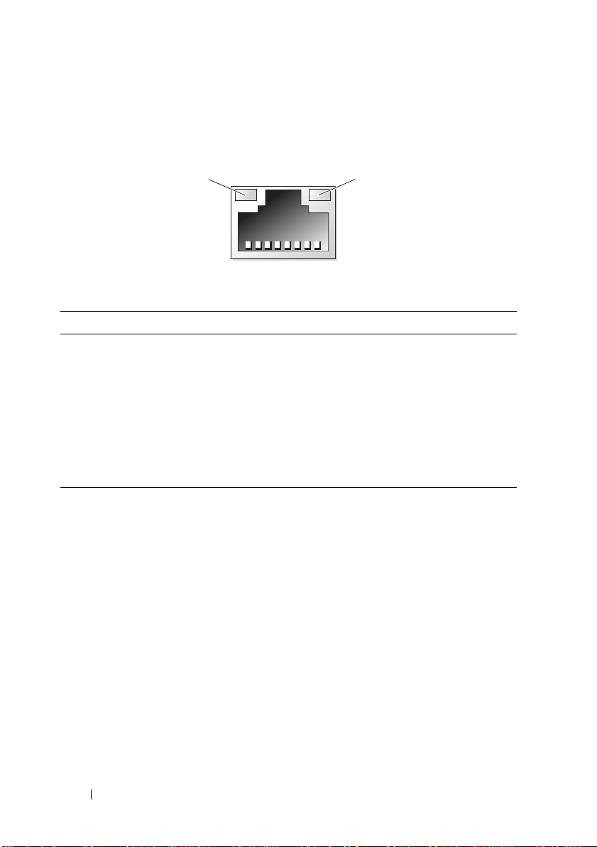
NIC Indicator Codes
1
2
Figure 1-3. NIC Indicator Codes
1 link indicator 2 activity indicator
Indicator Indicator Code
Link and activity indicators
are off
Link indicator is green The NIC is connected to a valid network link at
Link indicator is amber The NIC is connected to a valid network link at
Activity indicator is green
blinking
The NIC is not connected to the network.
1000 Mbps.
10/100 Mbps.
Network data is being sent or received.
16 About Your System
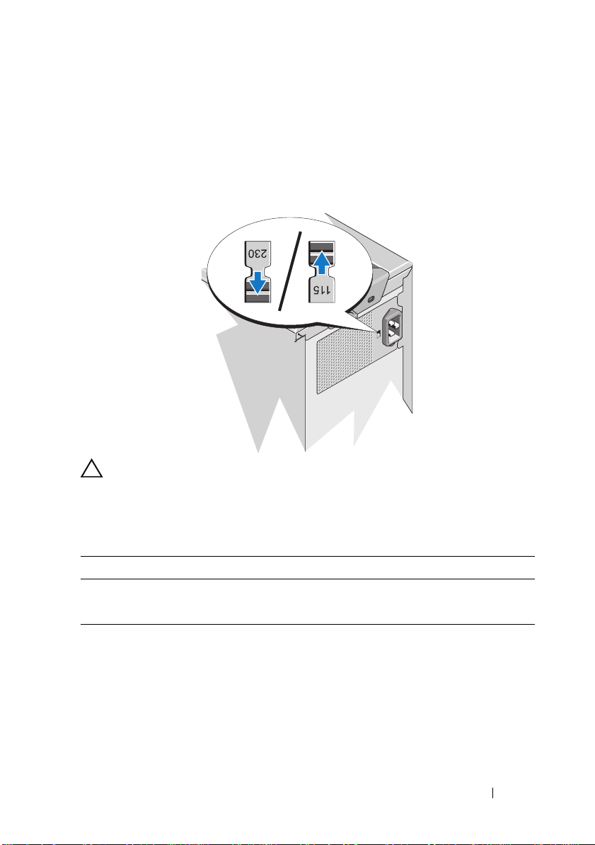
Power Selection
The voltage selection switch on the back panel of the system allows you to
select one of two primary voltage inputs.
Figure 1-4. Power Selection Switch
CAUTION: Be sure to set the voltage selection switch on the power supply for the
voltage that most closely matches the AC power available at your location.
Ensure that the switch is set to the proper voltage according to Table 1-1.
Table 1-1. Voltage Selection Switch
If your power source is: The voltage selection switch should be set to:
110 V
220 V
115
230
About Your System 17
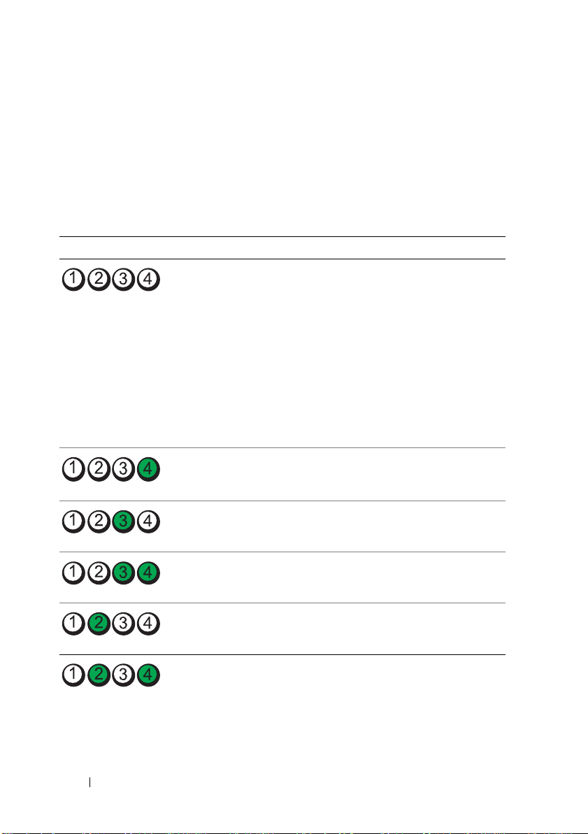
Diagnostic Lights
The four diagnostic indicator lights on the system front panel display error
codes during system startup. Table 1-2 lists the causes and possible corrective
actions associated with these codes. A highlighted circle indicates the light is
on; a non-highlighted circle indicates the light is off.
Table 1-2. Diagnostic Indicator Code
Code Causes Corrective Action
The system is in a normal
off condition or a possible
pre-BIOS failure has
occurred.
The diagnostic lights are
not lit after the system
successfully boots to the
operating system.
The system is in a normal
operating condition after
POST.
BIOS checksum failure
detected; system is in
recovery mode.
Possible processor failure. See "Troubleshooting the
Plug the system into a working
electrical outlet and press the
power button.
Information only.
See "Getting Help" on page 129.
Processor" on page 119.
Memory failure. See "Troubleshooting System
Possible expansion card
failure.
Possible video failure. See "Getting Help" on page 129.
18 About Your System
Memory" on page 113.
See "Troubleshooting Expansion
Cards" on page 118.
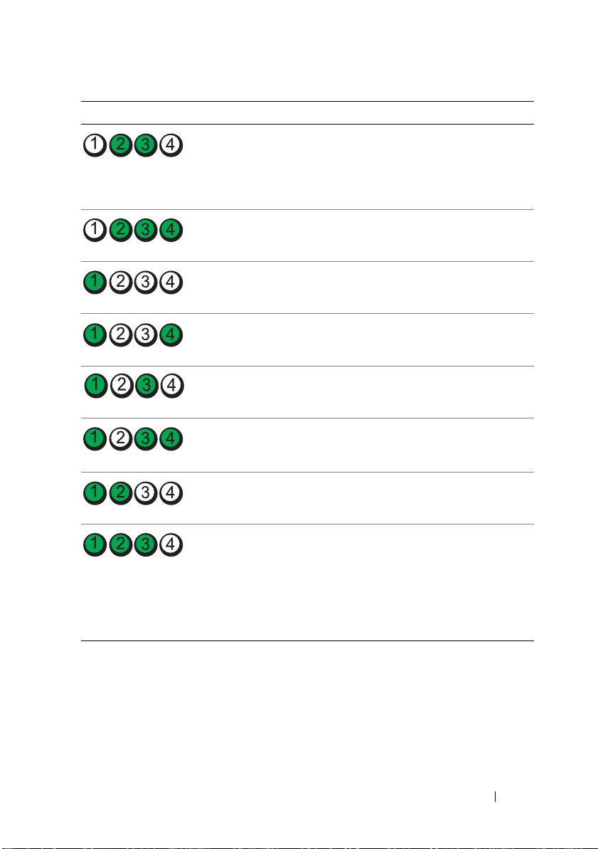
Code Causes Corrective Action
Hard drive failure. Ensure that the hard drives are
properly connected. See "Hard
Drives" on page 68 for
information on the drives
installed in your system.
Possible USB failure. See "Troubleshooting a USB
Device" on page 106.
No memory modules
detected.
System board failure. See "Getting Help" on page 129.
Memory configuration
error.
Possible system board
resource and/or system
board hardware failure.
Possible system resource
configuration error.
Other failure. Ensure that the optical drive and
See "Troubleshooting System
Memory" on page 113.
See "Troubleshooting System
Memory" on page 113.
See "Getting Help" on page 129.
See "Getting Help" on page 129.
hard drives are properly
connected. See "Troubleshooting
Your System" on page 105 for the
appropriate drive installed in your
system. If the problem persists,
see "Getting Help" on page 129.
About Your System 19

System Messages
System messages appear on the screen to notify you of a possible problem
with the system.
NOTE: If you receive a system message not listed in the table, check the
documentation for the application that is running when the message appears or the
operating system's documentation for an explanation of the message and
recommended action.
Message Causes Corrective Actions
Alert! BMC not
responding.
Rebooting.
Alert! BMC not
responding.
Power required
may exceed PSU
wattage.
Alert!
Continuing
system boot
accepts the risk
that system may
power down
without warning.
The BMC is not
responding to BIOS
communication either
because it is not
functioning properly or has
not completed
initialization. The system
reboots.
The BMC is hung.
The BMC was remotely
reset while system was
booting.
After AC recovery, the
BMC takes longer than
normal to boot.
Wait for the system to reboot.
Remove AC power to the
system for 10 seconds and
restart the system.
20 About Your System

Message Causes Corrective Actions
Alert! Power
required exceeds
PSU wattage.
Check PSU and
system
configuration.
Alert!
Continuing
system boot
accepts the risk
that system may
power down
without warning.
Alert! System
fatal error
during previous
boot.
BIOS
MANUFACTURING
MODE detected.
MANUFACTURING
MODE will be
cleared before
the next boot.
System reboot
required for
normal
operation.
BIOS Update
Attempt Failed!
The system configuration
of processor, memory
modules, and expansion
cards may not be supported
by the power supply.
An error caused the system
to reboot.
System is in manufacturing
mode.
Remote BIOS update
attempt failed.
If any system components
were just upgraded, return the
system to the previous
configuration. If the system
boots without this warning,
then the replaced
component(s) are not
supported with this power
supply. See "Power Supply" on
page 93.
Check other system messages
for additional information for
possible causes.
Reboot to take the system out
of manufacturing mode.
Retry the BIOS update. If
problem persists, see "Getting
Help" on page 129.
About Your System 21

Message Causes Corrective Actions
Caution!
NVRAM_CLR jumper
is installed on
system
board.Please run
SETUP.
CPU set to
minimum
frequency.
Current boot mode
is set to UEFI.
Please ensure
compatible
bootable media is
available. Use
the system setup
program to change
the boot mode as
needed.
Decreasing
available
memory.
Embedded NIC
NIC
y
:
OS NIC=
|DISABLED>
Management
Shared NIC=
x
<ENABLED
,
<ENABLED
NVRAM_CLR jumper is
installed in the clear
setting. CMOS has been
cleared.
The processor speed may
be intentionally set lower
for power conservation.
The system failed to boot
because UEFI boot mode is
enabled in BIOS and the
boot operating system is
non-UEFI.
Faulty or improperly
installed memory modules.
and
The operating system NIC
interface is set in BIOS.
The Management Shared
NIC interface is set in
management tools.
Move the NVRAM_CLR
jumper to the default position
(pins 3 and 5). See Figure 6-1
for jumper location. Restart
the system and re-enter the
BIOS settings. See "Using the
System Setup Program and
UEFI Boot Manager" on
page 35.
If not an intentional setting,
check other system messages
for possible causes.
Ensure that the boot mode is
set correctly and that the
proper bootable media is
available. See "Using the
System Setup Program and
UEFI Boot Manager" on
page 35.
Reseat the memory modules.
See "Troubleshooting System
Memory" on page 113.
Check the system
management software or the
System Setup program for
NIC settings. If a problem is
indicated, see
"Troubleshooting a NIC" on
page 107.
|DISABLED>
22 About Your System

Message Causes Corrective Actions
Error 8602 Auxiliary Device
Failure. Verify
that mouse and
keyboard are
securely
attached to
correct
connectors.
Gate A20 failure. Faulty keyboard controller;
General failure. The operating system is
Invalid
configuration
information please run SETUP
program.
Keyboard
controller
failure.
Keyboard data
line failure.
Keyboard stuck
key failure.
Keyboard fuse has
failed.
Mouse or keyboard cable is
loose or improperly
connected.
Defective mouse or
keyboard.
faulty system board.
unable to carry out the
command.
An invalid system
configuration caused a
system to halt.
Faulty keyboard controller;
faulty system board.
Keyboard cable connector
is improperly connected or
the keyboard is defective.
Overcurrent detected at
the keyboard connector.
Reseat the mouse or keyboard
cable.
Ensure that the mouse or
keyboard is operational. See
"Troubleshooting a USB
Device" on page 106.
See "Getting Help" on
page 129.
This message is usually
followed by specific
information. Note the
information, and take the
appropriate action to resolve
the problem.
Run the System Setup
program and review the
current settings. See "Using
the System Setup Program and
UEFI Boot Manager" on
page 35.
See "Getting Help" on
page 129.
Reseat the keyboard cable. If
the problem persists, see
"Troubleshooting a USB
Device" on page 106.
See "Getting Help" on
page 129.
About Your System 23

Message Causes Corrective Actions
Local keyboard
may not work
because all user
accessible USB
ports are
disabled. If
operating
locally, power
cycle the system
and enter system
setup program to
change settings.
Manufacturing
mode detected.
Maximum rank
count exceeded.
The following
DIMM has been
disabled:
Memory address
line failure at
address
value
x
, read
expecting
The USB ports are disabled
in the system BIOS.
System is in manufacturing
mode.
Invalid memory
configuration. The system
will run but with the
specified memory module
disabled.
Faulty or improperly
installed memory modules.
Power down and restart the
system from the power button,
and then enter the System
Setup program to enable the
USB port(s). See "Entering the
System Setup Program" on
page 36.
Reboot to take the system out
of manufacturing mode.
Ensure that the memory
modules are installed in a valid
configuration. See "General
Memory Module Installation
Guidelines" on page 80.
See "Troubleshooting System
Memory" on page 113.
value.
Memory double
word logic
failure at
address
value
, read
expecting
Faulty or improperly
installed memory modules.
See "Troubleshooting System
Memory" on page 113.
value.
Memory
Initialization
Warning: Memory
size may be
reduced.
Invalid memory
configuration. The system
will run but with less
memory than is physically
available.
Ensure that the memory
modules are installed in a valid
configuration. See "General
Memory Module Installation
Guidelines" on page 80.
24 About Your System

Message Causes Corrective Actions
Memory odd/even
logic failure at
address,
value
read
expecting
Faulty or improperly
installed memory modules.
See "Troubleshooting System
Memory" on page 113.
value.
Memory
write/read
failure at
address
value
, read
expecting
Faulty or improperly
installed memory modules.
See "Troubleshooting System
Memory" on page 113.
value.
Memory set to
minimum
frequency.
Memory tests
terminated by
keystroke.
MEMTEST lane
failure
detected on
The memory frequency
may be intentionally set
lower for power
conservation.
The current memory
configuration may support
only the minimum
frequency.
POST memory test was
terminated by pressing the
spacebar.
Invalid memory
configuration. A
mismatched memory
x.
module is installed.
If not an intentional setting,
check any other system
messages for possible causes.
Ensure that your memory
configuration supports the
higher frequency. See "General
Memory Module Installation
Guidelines" on page 80.
Information only.
Ensure that the memory
modules are installed in a valid
configuration. See "General
Memory Module Installation
Guidelines" on page 80.
About Your System 25

Message Causes Corrective Actions
No boot device
available.
No boot sector on
hard drive.
No timer tick
interrupt.
PCI BIOS failed
to install.
PCIe Training
Error: Expected
Link Width is
Actual Link Width
is
y
.
Faulty or missing optical
drive subsystem, hard drive,
or hard-drive subsystem, or
no bootable USB key
installed.
Incorrect configuration
settings in System Setup
program, or no operating
system on hard drive.
Faulty system board. See "Getting Help" on
PCIe device BIOS (Option
ROM) checksum failure
detected during shadowing.
Cables to expansion card(s)
loose; faulty or improperly
installed expansion card(s).
Faulty or improperly
installed PCIe card in the
x
,
specified slot.
Use a bootable USB key, CD,
or hard drive. If the problem
persists, see "Troubleshooting
a USB Device" on page 106,
"Troubleshooting an Optical
Drive" on page 115, and
"Troubleshooting a Hard
Drive" on page 117. See "Using
the System Setup Program and
UEFI Boot Manager" on
page 35 for information on
setting the order of boot
devices.
Check the hard-drive
configuration settings in the
System Setup program. See
"Using the System Setup
Program and UEFI Boot
Manager" on page 35. If
necessary, install the operating
system on your hard drive. See
your operating system
documentation.
page 129.
Reseat the expansion card(s).
Ensure that all appropriate
cables are securely connected
to the expansion card(s). If the
problem persists, see
"Troubleshooting Expansion
Cards" on page 118.
Reseat the PCIe card in the
specified slot number. See
"Troubleshooting Expansion
Cards" on page 118. If the
problem persists, see "Getting
Help" on page 129.
26 About Your System

Message Causes Corrective Actions
Plug & Play
Configuration
Error.
Quad rank DIMM
detected after
single rank or
dual rank DIMM in
socket.
Read fault.
Requested sector
not found.
SATA Port x
device not found.
x
SATA port
device autosensing error.
SATA port
device
configuration
error.
SATA port
device error.
x
x
Error encountered in
initializing PCIe device;
faulty system board.
Invalid memory
configuration.
The operating system
cannot read from the hard
drive, optical drive, or USB
device; the system could
not find a particular sector
on the disk, or the
requested sector is
defective.
There is no device
connected to the specified
SATA port.
The drive connected to the
specified SATA port is
faulty.
Install the NVRAM_CLR
jumper in the clear position
(pins 1 and 3) and reboot the
system. See Figure 6-1 for
jumper location. If the
problem persists, see
"Troubleshooting Expansion
Cards" on page 118.
Ensure that the memory
modules are installed in a valid
configuration. See "General
Memory Module Installation
Guidelines" on page 80.
Replace the optical medium,
USB medium or device.
Ensure that the USB or SATA
cables are properly connected.
See "Troubleshooting a USB
Device" on page 106,
"Troubleshooting an Optical
Drive" on page 115, and
"Troubleshooting a Hard
Drive" on page 117 for the
appropriate drive(s) installed
in your system.
Information only.
Replace the faulty drive.
About Your System 27

Message Causes Corrective Actions
Sector not found.
Seek error.
Seek operation
failed.
Shutdown
failure.
The amount of
system memory has
changed.
Faulty hard drive, USB
device or medium.
General system error. See "Getting Help" on
Memory has been added or
removed or a memory
module may be faulty.
Replace the USB medium or
device. Ensure that the USB
cables are properly connected.
See "Troubleshooting a USB
Device" on page 106 or
"Troubleshooting a Hard
Drive" on page 117 for the
appropriate drive(s) installed
in your system.
page 129.
If memory has been added or
removed, this message is
informative and can be
ignored. If memory has not
been added or removed, check
the SEL to determine if singlebit or multi-bit errors were
detected and replace the faulty
memory module. See
"Troubleshooting System
Memory" on page 113.
28 About Your System

Message Causes Corrective Actions
The following
DIMMs should
match
in
geometry:
x,x,...
The following
DIMMs should
match
count:
The following
DIMMs should
match in size:
in rank
x,x,
...
Invalid memory
configuration. The
specified memory modules
do not match in size,
number of ranks, or
number of data lanes.
Ensure that the memory
modules are installed in a valid
configuration. See "General
Memory Module Installation
Guidelines" on page 80.
x,x,...
The following
DIMMs should
match
in size
and geometry:
x,x,...
The following
DIMMs should
match
in size
and rank count:
x,x,...
Thermal sensor
not detected on
x.
Time-of-day
clock stopped.
Time-of-day not
set - please run
SETUP program.
A memory module without
a thermal sensor is installed
in the specified memory
slot.
Faulty battery or faulty
chip.
Incorrect Time or Date
settings; faulty system
battery.
Replace the memory module.
See "System Memory" on
page 80.
See "Troubleshooting the
System Battery" on page 110.
Check the Time and Date
settings. See "Using the
System Setup Program and
UEFI Boot Manager" on
page 35. If the problem
persists, replace the system
battery. See "System Battery"
on page 91.
About Your System 29

Message Causes Corrective Actions
Timer chip
counter 2 failed.
TPM
configuration
operation
honored. System
will now reset.
TPM
configuration
operation is
pending. Press
(I) to Ignore OR
(M) to Modify to
allow this change
and reset the
system.
WARNING:
Modifying could
prevent
security.
TPM failure. A TPM function has failed. See "Getting Help" on
Unable to launch
System Services
image. System
halted!
Unexpected
interrupt in
protected mode.
Faulty system board. See "Getting Help" on
page 129.
A Trusted Platform Module
(TPM) configuration
command has been
entered. The system will
reboot and execute the
command.
This message displays
during system restart after
a TPM configuration
command has been
entered. User interaction is
required to proceed.
System halted after F10
keystroke because System
Services image is either
corrupted in the system
firmware or has been lost
due to system board
replacement.
Improperly seated memory
modules or faulty keyboard
or mouse controller chip.
Information only.
Enter I or M to proceed.
page 129.
Restart the system and update
the USC repository to the
latest software to restore full
functionality. See the USC
user documentation for more
information.
Reseat the memory modules.
See "Troubleshooting System
Memory" on page 113. If the
problem persists, see "Getting
Help" on page 129.
30 About Your System
 Loading...